EP3973935A1 - Improved transfer head, method and apparatus for transferring a pad from a pick-up location to a drop-off location - Google Patents
Improved transfer head, method and apparatus for transferring a pad from a pick-up location to a drop-off location Download PDFInfo
- Publication number
- EP3973935A1 EP3973935A1 EP21152906.0A EP21152906A EP3973935A1 EP 3973935 A1 EP3973935 A1 EP 3973935A1 EP 21152906 A EP21152906 A EP 21152906A EP 3973935 A1 EP3973935 A1 EP 3973935A1
- Authority
- EP
- European Patent Office
- Prior art keywords
- location
- transfer head
- pad
- transfer
- pick
- Prior art date
- Legal status (The legal status is an assumption and is not a legal conclusion. Google has not performed a legal analysis and makes no representation as to the accuracy of the status listed.)
- Granted
Links
Images

Classifications
-
- A—HUMAN NECESSITIES
- A61—MEDICAL OR VETERINARY SCIENCE; HYGIENE
- A61F—FILTERS IMPLANTABLE INTO BLOOD VESSELS; PROSTHESES; DEVICES PROVIDING PATENCY TO, OR PREVENTING COLLAPSING OF, TUBULAR STRUCTURES OF THE BODY, e.g. STENTS; ORTHOPAEDIC, NURSING OR CONTRACEPTIVE DEVICES; FOMENTATION; TREATMENT OR PROTECTION OF EYES OR EARS; BANDAGES, DRESSINGS OR ABSORBENT PADS; FIRST-AID KITS
- A61F13/00—Bandages or dressings; Absorbent pads
- A61F13/15—Absorbent pads, e.g. sanitary towels, swabs or tampons for external or internal application to the body; Supporting or fastening means therefor; Tampon applicators
- A61F13/15577—Apparatus or processes for manufacturing
- A61F13/15764—Transferring, feeding or handling devices; Drives
-
- B—PERFORMING OPERATIONS; TRANSPORTING
- B65—CONVEYING; PACKING; STORING; HANDLING THIN OR FILAMENTARY MATERIAL
- B65G—TRANSPORT OR STORAGE DEVICES, e.g. CONVEYORS FOR LOADING OR TIPPING, SHOP CONVEYOR SYSTEMS OR PNEUMATIC TUBE CONVEYORS
- B65G47/00—Article or material-handling devices associated with conveyors; Methods employing such devices
- B65G47/22—Devices influencing the relative position or the attitude of articles during transit by conveyors
- B65G47/24—Devices influencing the relative position or the attitude of articles during transit by conveyors orientating the articles
- B65G47/248—Devices influencing the relative position or the attitude of articles during transit by conveyors orientating the articles by turning over or inverting them
- B65G47/252—Devices influencing the relative position or the attitude of articles during transit by conveyors orientating the articles by turning over or inverting them about an axis substantially perpendicular to the conveying direction
-
- B—PERFORMING OPERATIONS; TRANSPORTING
- B65—CONVEYING; PACKING; STORING; HANDLING THIN OR FILAMENTARY MATERIAL
- B65G—TRANSPORT OR STORAGE DEVICES, e.g. CONVEYORS FOR LOADING OR TIPPING, SHOP CONVEYOR SYSTEMS OR PNEUMATIC TUBE CONVEYORS
- B65G47/00—Article or material-handling devices associated with conveyors; Methods employing such devices
- B65G47/74—Feeding, transfer, or discharging devices of particular kinds or types
- B65G47/84—Star-shaped wheels or devices having endless travelling belts or chains, the wheels or devices being equipped with article-engaging elements
- B65G47/846—Star-shaped wheels or wheels equipped with article-engaging elements
- B65G47/848—Star-shaped wheels or wheels equipped with article-engaging elements the article-engaging elements being suction or magnetic means
-
- B—PERFORMING OPERATIONS; TRANSPORTING
- B65—CONVEYING; PACKING; STORING; HANDLING THIN OR FILAMENTARY MATERIAL
- B65G—TRANSPORT OR STORAGE DEVICES, e.g. CONVEYORS FOR LOADING OR TIPPING, SHOP CONVEYOR SYSTEMS OR PNEUMATIC TUBE CONVEYORS
- B65G47/00—Article or material-handling devices associated with conveyors; Methods employing such devices
- B65G47/74—Feeding, transfer, or discharging devices of particular kinds or types
- B65G47/90—Devices for picking-up and depositing articles or materials
- B65G47/91—Devices for picking-up and depositing articles or materials incorporating pneumatic, e.g. suction, grippers
- B65G47/915—Devices for picking-up and depositing articles or materials incorporating pneumatic, e.g. suction, grippers provided with drive systems with rotary movements only
Definitions
- the invention pertains to the technical field of manufacturing absorbent article. More particularly, the invention relates to a method and apparatus for transferring pads and more particularly to transferring pads using web accumulation devices. In particular, the invention relates to a transfer head used for the transferring of said pad.
- Absorbent articles such as taped diapers or pant diapers, for example, may be manufactured by a process where discrete articles, that will be referenced as pads from here on out, such as a chassis of a taped diaper or a pant diaper comprising a topsheet, a backsheet, and an absorbent core, for example, are applied to one or more moving webs of components, such as webs of front and rear belt portions, or a single web of front belt portions or rear belt portions, for example.
- a transfer wheel may be provided that comprises at least one transfer head and a frame defining a rotation axis. The transfer heads may circumnavigate about the rotation axis in an orbit.
- Each of the transfer heads may comprise a transfer surface that is configured to engage one or more of the pads.
- the transfer heads may pick up the pad at a pick-up location and place the pad at a drop-off location within the orbit.
- the transfer device may rotate the discrete articles about 90 degrees, or other suitable angles, between the pick-up location and the drop-off location about a second rotation axis that is perpendicular, or substantially perpendicular, to the rotation axis.
- Some transfer wheel that rotate and transfer discrete articles are known in the art as "turn and repitch" units because the units turn the discrete articles and repitch them (i.e., change the spacing or "pitch" between them) between the pick-up location and the drop-off location.
- the invention aims to provide a method and apparatus which ensures that the transferring process is as efficient as possible notably by lowering the clearance between the different elements in the process line while maintaining sufficient robustness.
- the present invention provides a transfer head configured for the transfer of a pad from a pick-up location to a drop-off location.
- the transfer head comprises a support module comprising a vacuum mean, and a core module comprising an elastic mean.
- module refers elements or parts of the transfer head, it can also correspond to layers in the transfer head.
- vacuum mean it is implied an element that can guarantee a vacuum, i.e. generate a negative fluid pressure and/or a positive fluid pressure, or more specifically an element that can ensure the passage of airflow in one direction or the opposite to generate a difference of pressure, within the transfer head.
- Such vacuum mean can correspond to at least one hole that can ensure that the support module, and the transfer head, is in fluid communication with a pump.
- the vacuum mean can also correspond to a vacuum manifold or a pump. The vacuum mean enables the transfer head to generate a negative fluid pressure and/or a positive fluid pressure.
- the transfer head according to the present invention allows the transfer of the pad from a pick-up location to a drop-off location thanks to the support module that can maintain the pad onto the transfer head with the vacuum induced by the vacuum manifold and the elastic mean present in the core module enables the transfer head to adapt to the shape of the other elements in the process line, such as the feeding rolls, in order to compensate the clearance and leave no space between the transfer head and any element that can come into contact with the transfer element.
- the space between the transfer element and the other elements in the process is reduced, thus there is less distance and the transfer of the pad from the roller feed to the transfer head is reduced. This improves significantly the stability of the transfer from one element to the other, there are less risk to damage the transfer head if it has a module or element that can absorb shocks.
- the elastic mean comprises an elastic material.
- the elastic mean consists essentially of an elastic material and more preferably the elastic mean consists of an elastic material.
- the core module comprises an elastic material for example elastomers such as rubbers (synthetic and natural), thermoplastic elastomers, polysulfide rubbers.
- the core module consists essentially of an elastic material for example elastomers such as rubbers (synthetic and natural), thermoplastic elastomers, polysulfide rubbers.
- the core module consists of an elastic material for example elastomers such as rubbers (synthetic and natural), thermoplastic elastomers, polysulfide rubbers.
- the core module comprises a polyurethane foam and/or polyethylene foam and/or rubber foam and/or polyamide foam.
- the core module consists essentially of a polyurethane foam and/or polyethylene foam and/or rubber foam and/or polyamide foam and more preferably, the core module consists of a polyurethane foam and/or polyethylene foam and/or rubber foam and/or polyamide foam.
- the elastic means is a spring.
- the transfer element further comprises an additional coating layer comprising an antiadhesive material.
- the transfer head further comprises a coating layer, said coating layer comprising an antiadhesive material, the core module being arranged between the support module and the coating layer.
- the transfer element is arranged in a way that the core module is located between the support module and the coating layer.
- the antiadhesive coating contains polytetrafluoroethylene (Teflon) and/or polysiloxane (silicone) and/or polyurethane and/or ceramics.
- the transfer head is elongated in a longitudinal direction defining a first and second longitudinal ends, the transfer head having a first rounded edge at the first longitudinal end and/or a second rounded edge at the second longitudinal end.
- the core module comprises vacuum holes.
- the coating layer comprises vacuum holes.
- the distribution of vacuum holes is higher at the first rounded edge than at the second rounded edge. In other words, there are more vacuum holes at the first rounded edge than at the second rounded edge
- transfer head according to the invention is not limited to each embodiment separately and each feature mentioned above and afterwards can be taken individually or in combination.
- the invention also concerns a method of transferring a pad from a pick-up location to a drop-off location, the method comprising:
- the transfer head provides a negative fluid pressure to the pad at the pick-up location and/or a positive fluid pressure to the pad at the drop-off location.
- the invention also concerns an apparatus for manufacturing an absorbent article comprising
- the feeding roll and the transfer device are arranged in such way that at the pick-up location, the core module of the transfer head is adapted to be deformed by the pad and/or the feeding roll.
- the invention also concerns a method of manufacturing an absorbent articles, the method comprising:
- the current invention concerns a transfer head configured for the transfer of a pad from a pick-up location to a drop-off location.
- the current invention also concerns a method of transferring a pad from a pick-up location to a drop-off location.
- the current invention also concerns an apparatus for manufacturing an absorbent article using said method of transferring a pad from a pick-up location to a drop-off location.
- a compartment refers to one or more than one compartment.
- the value to which the modifier "about” refers is itself also specifically disclosed.
- Figure 1 illustrates schematically from a side view a module, or a part, of the process to manufacture an absorbent article, in accordance with an embodiment of the present invention.
- Figure 1 shows namely the transfer assembly 2 of a pad 6.
- the transfer assembly 2 comprises a transfer device 4 configured to transfer one or more pads 6 to one or more webs 8.
- the pad 6 being transferred may be a chassis of an absorbent article, such as a diaper, a pant, or adult incontinence product.
- the chassis of an absorbent article may comprise a topsheet, a backsheet, and an absorbent core positioned at least partially intermediate the topsheet and the backsheet.
- the chassis may also comprise one more acquisition material and/or distribution material at least partially intermediate the topsheet and the absorbent core.
- the chassis may also comprise one or more pairs of leg cuffs.
- the webs 8 being conveyed may be front and rear belts that attach to ends of the chassis. In other instances, a single belt (e.g., a rear belt) may be attached to only one end of the chassis.
- the transfer assembly 2 comprises conveying means 11,12,14 corresponding here to a first roll 11 which acts as a feeding roll 11, a second roll 12 which acts as a cutting roll 12 and a third roll 14 which acts as an anvil 14 for the cutting roll 12.
- the transfer assembly 2 may comprise further conveying means.
- the transfer assembly may also comprise less conveying means, for example the feeding roll 11 can act as a feeding roll and as an anvil for the cutting roll 12 altogether.
- the web of pads 10 may be separated into individual pads 6 by the separation means 12,14.
- the anvil roll 14 is configured to transfer each pad 6 to the feeding roll 11 and may also act as an anvil for the cutting roll 12.
- the cutting roll 12 comprises one or more knives 18 depending on the desired pad length.
- the anvil roll 14 and the cutting roll 12 rotate in opposite directions, namely the anvil roll 14 rotates in a clockwise direction (represented by arrow B) and the cutting roll 12 rotates in the counter clockwise direction (illustrated by arrow C).
- each of the knives 18 comes into contact with the continuous web of pads 10 and presses against the anvil roll 14 to separate each single pad 6 and allow the single pad 6 to move onto the feeding roll 11.
- the feeding roll 11 rotates in an opposite direction than the anvil roll 14, i.e.
- the feeding roll 11 may have vacuum to hold the individual pads 6 unto its surface until the pad is transferred to the transfer device 4.
- the transfer device 4 comprises a frame 20 with a center and a plurality of arms 22.
- a transfer head 24 is located at the end of each arm 22.
- Each individual pad 6 is applied onto a transfer head 24 that guides the pad 6 from a pick-up location to a drop-off location.
- the feeding roll 11 may apply a positive fluid pressure to the pad, portions thereof, to blow on the pad and cause the pad 6 to transfer to a transfer head 24.
- the transfer head 24 may apply a negative fluid pressure to the pad, portions thereof, to suck on the pad and cause said pad 6 to stay on the surface of the transfer head 24.
- both embodiments can be combined.
- the transfer between the feeding roll 11 and the transfer head 24 is an important step regarding the efficiency of the transfer process and is located at a point that will be called the pick-up location 26 from here on out.
- Figure 2 and Figure 3 both illustrate a close-up of said pick-up location 26 at different stage of the transfer of the pad 6.
- Figure 2 represents the pick-up location 26 at when the pad 6 is halfway transferred onto the transfer head 24.
- figure 3 illustrates the pick-up location 26 at a timepoint beforehand notably when the pad 6 is starting to be transferred onto the transfer head 24.
- the feeding roll 11 is separated from the transfer head 24 by a distance d which represents approximately 10 mm, said distance d correspond to the clearance necessary for the transfer head 24 being able to pass and pick up the pad 6. Because of that distance d, the transfer of the pad 6 from the feeding roll 11 unto the transfer head 24 takes a few microseconds which can create an instability and possible jamming in the process. Thus in order to have an efficient transfer assembly, the distance d must be as small as possible in order to limit the time of transfer between the feeding roll 11 and the transfer head 24. The issue with a conventional transfer device 4 is that this distance d cannot be lowered.
- the invention provides a transfer head 24 configured to transfer a pad 6 from a pick-up location 26 to a drop-off location 62, said transfer head 24 comprises a support module comprising a vacuum mean, and a core module comprising an elastic mean.
- vacuum mean it is implied an element that can guarantee a vacuum, i.e. generate a negative fluid pressure and/or a positive fluid pressure, or more specifically an element that can ensure the passage of airflow in one direction or the opposite to generate a difference of pressure, within the transfer head.
- the vacuum mean can ensure a vacuum with a negative fluid pressure going from -2 kPa up to -20 kPa.
- the vacuum mean can ensure a vacuum with a positive fluid pressure going from 2 kPa up to 20 kPa.
- Such vacuum mean can correspond to at least one hole that can ensure that the support module, and the transfer head, is in fluid communication with a manifold and/or pump.
- the vacuum mean can also correspond to a vacuum manifold or a pump. The vacuum mean enables the transfer head to generate a negative fluid pressure and/or a positive fluid pressure within its structure.
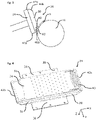
- the transfer head 24 as illustrated in Figure 4 comprises a support module 28 which can correspond to a casing, or container, that can be made of a robust material such as plastic or metal.
- the support module 28 comprises a vacuum mean (not illustrated) to ensure a negative fluid pressure and enable the pad 6 to get sucked onto the transfer head 24.
- the support module 28 can present holes so that the support module 28 is in fluid communication with a vacuum manifold or pump that can suck or blow air within the support module 28 and the transfer head 24.
- the transfer head 24 according to the invention also comprises a core module 30 comprising an elastic mean 32.
- the elastic mean 32 enables the core module to be deformed under a distorting influence and to return to its original shape once the influence is removed.
- the elastic mean can be mechanical and correspond to one or more springs, preferably compression springs such as leaf spring or coil spring.
- the elastic mean can also be chemical and correspond to the core module 30 comprising an elastic material such as elastomers rubbers (synthetic and natural), thermoplastic elastomers, polysulfide rubbers.
- the core module 30 comprises of a Polyurethane (PU) foam and/or Polyethylene (PE) foam and/or rubber foam and/or Polyamide (PA) foam.
- PU foams have the advantage of being lighter than the other embodiment (spring or rubbers) and have an excellent ability to revert to its original shape.
- the transfer head 24 further comprises an additional coating layer 34 comprising an antiadhesive coating.
- the antiadhesive coating improves the deposit of the pad 6 onto the webs 8 at the drop-off location by ensuring that the pad 6 does not stay stuck onto the transfer head 24.
- the antiadhesive coating may correspond to a layer of Polytetrafluoroethylene (Teflon) and/or polysiloxane (silicone) and/or polyurethane and/or ceramics.
- each transfer head 24 is attached to an arm 22 of the frame of the transfer device 4.
- the support module 28 can be directly fixed to the arm 22 or the transfer head 24 can further comprise a fixation plate 36 made out of robust material such as plastic or metal with fixation means 38, for example a plurality of holes as illustrated in figure 4 , threaded or not, to enable a rod, threaded or not, to screw the fixation plate onto the arm 22 of the frame of the transfer device 4.
- fixation means 38 are not limited to this embodiment and can correspond to other fixation elements such as clips, snap-fits, glue for example.
- the support module 28 and the fixation plate 36 can be in one single piece, or unitary piece, i.e. form a continuity of matter. It is understood from this description, that the support module 28 and the fixation plate 36 are made out of a material that is more robust than the core module 30 and the coating layer 34.
- the transfer head 24 is arranged in a way that the core module 30 is located between the support module 28 and the coating layer 34. Furthermore, should the transfer head 24 comprise a fixation plate 36 that is distinct from the support module 28, then the transfer head 24 is arranged in a way that the fixation plate at the lowest point of the transfer head 24. The support module 28 is then located on the fixation plate 36, between the fixation plate 36 and the core module 30. The core module 30 is placed on the support module 28, between the support module 28 and the coating layer 34. The coating layer 34 is recovering the core module 30.
- the fixation plate 36 and the support module 28 can be made as an unique single piece or as two separate parts.
- the fixation plate 36 and the support module 28 can be made in the same material or of two different materials.
- the transfer head 24 can comprise a fixation plate 36 made out of metal and a support module 28 made out of plastic.
- the transfer head comprises vacuum holes 40, or fluid ports. These vacuum holes are present within the coating layer 34 and the core module 30 and enable the vacuum manifold to ensure the negative fluid pressure more efficiently and ensure that the pad stays more securely on the surface of the coating layer 34.
- the transfer head 24 extends in longitudinal (X), transverse, or transversal, (Y) and vertical (Z) directions.
- the support module 28, core module 30 and coating layer 34 extends more in the longitudinal direction in than the transversal and vertical directions.
- the transfer head 24 has an elongated shape in the longitudinal direction.
- the transfer head 24 has two ends in the longitudinal direction 42a,42b.
- the first longitudinal end 42a correspond to the end of the transfer head 24 that first comes into contact with the pad 6 as illustrated in Figure 2 at the pick-up location 26.
- the second longitudinal end 42b correspond to the end of the transfer head that comes last into contact with the pad 6.
- the distribution, or density, of vacuum holes is different between the first longitudinal end 42a and the second longitudinal end 42b.
- the first and second longitudinal ends 42a,42b do not have the same numbers of vacuum holes.
- the first longitudinal end 42a has a larger distribution of vacuum holes than the second longitudinal end 42b or in other words there are more vacuum holes 40 at the first longitudinal end 42a than at the second longitudinal end 42b.
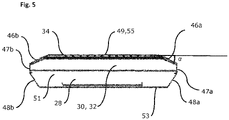
- the transfer head 24 can have rounded edges 46a,46b,48a,48b at each longitudinal ends 42a,42b. More specifically, the core module 30 has rounded edges 46a,46b at each longitudinal ends 42a,42b. This ensures that the rotation of the transfer head 24 is less impeded by the feeding roll 11, this will be further explained afterwards.
- the support module 28 can also present rounded edges 48a,48b.
- the first rounded edge 46a correspond to the edge of the transfer head, specifically of the core module 30 at the first longitudinal end 42a.
- the second rounded edge 46b correspond to the edge of the transfer head, specifically of the core module 30 at the second longitudinal end 42b. The same logics applies to the rounded edge 48a,48b of the support module 28.
- the core module 30 has a section in a shape of an irregular hexagon.
- the transfer head 24 and notably the support module 28 and the core module 30 have the shape of a rectangular prism that has two longitudinal surfaces, or sides, 47a,47b at the end longitudinal ends (X-direction), two transversal surfaces, or sides, 51 at the transversal ends (Y-direction) and a top surface, or top side, 49 and bottom surface, or bottom side 53 (Z-direction).
- the longitudinal surfaces 47a,47b are two parallel planes that each extends in the transverse (Y) and vertical (Z) directions and are apart in the longitudinal direction (X) thus defining the length of the transfer head 24.
- the transfer head 24 has rounded edges. Namely the longitudinal surfaces 47a,47b are adjoined to the top (49) and/or bottom (51) surfaces by a chamfer (46a,46b,48a,48b).
- a chamfer 46a links a longitudinal surface 47a to the top side 49 of the transfer head 24, i.e. an inclined plane 46a, or slope, makes the transition between the top side 49 and a longitudinal surface 47a. It can also be said that the top side 49 and the longitudinal side 47a have edges that are softened by an inclined plane.
- the inclined plane 46a can be at an angle a (noted afterwards in degrees) that is comprised in a range between 25 degree and 70 degree included, preferably an angle between 35 degree and 55 degree, more preferably at an angle between 40 degree and 50 degree. This prevents damage to the edges of the transfer head 24.
- the invention is not limited to this embodiment, in the sense that there can be one or more inclined planes to soften the edges.
- the rounded edge 46a can also corresponds to a convex non-tangent rounding or concave fillet or any other smooth transition replacing the single edge between the top 49 and longitudinal 47a surfaces and having an arc-shaped cross-section.
- the core module 30 has rounded edges 46a,46b between the top side 49 and the longitudinal surfaces 47a,47b, the coating layer 34, being a covering layer on the core module 30, adopts the same contour, or shape, as the core module 30.
- the support module 28 can also have rounded edges 48a,48b between the bottom side 53 and the longitudinal surfaces 47a,47b.
- the middle portion 55 of the top surface 49 located between the rounded edges 46a,46b is sensibly flat as illustrated on figure 5 .
- the transition between the top side 49 and the longitudinal side 47 corresponds to a beveled edge where the longitudinal end 42a,42b corresponds to the support module 28 and the core module 30 doesn't present any flat surface at the longitudinal end 42a,42b, i.e. directly links the longitudinal surface 47a, 47b which corresponds to the support module 28 to the top surface 49.
- the support module 28 can be in the form of a container, i.e. a element with side walls and a bottom wall and defining a hollow space, the core module 30 can be partially received in said hollow space and protrude from the support module 28 on the side opposite of the bottom wall.
- the coating layer 34 covering the part of the core module 30 destined to receive the pad 6, i.e the side that is opposite of the bottom wall contained in the hollow space.
- the support module 28 can also be in the form of a solid plate, with a flat surface and no hollow space, with the core module 30 laying onto the plate, the coating layer 34 being arranged on the side of the core module 30 that is opposite to the side of the core module 30 laying against the solid plate of the support module 28.
- the support module 28 is 5 to 20 mm thick (in the z direction), preferably 10 to 15 mm high, the core module 30 is 20 to 70 mm thick (in the z direction), preferably 40 to 60 mm thick and the coating layer 34 is 0,5 to 5 mm thick.
- the support module 28 comprises vacuum means.
- the support module 28 can have holes in the bottom wall or in the solid plate mentioned above so that the bottom part of the support module can be in fluid communication with a vacuum pump that can suck or blow air.
- the core module 30 and the coating layer 34 also comprise vacuum holes 40 to enable the vacuum generated within the support module 28 to reach the surface destined to receive the pad 6.
- a vacuum pump can be arranged within the frame 20 with a center, the arms 22 can be hollow and the air can be either sucked from or blown into the transfer head 24 through the holes in the support module 28 and core module 30 and coating layer 34 to generate a negative or positive fluid pressure. It is also possible to arrange a vacuum manifold within the support module 28 to ensure the generation of a negative or positive fluid pressure.
- the vacuum holes 40 are present on the top surface 49 and the distribution of vacuum holes 40 is more important on the first rounded edge 46a located at the first longitudinal end 42a.
- the distribution of vacuum holes 40 on the middle portion 55 is lower than on the first rounded edge 46a.
- the distribution of vacuum holes 40 on the second rounded edge 46b located at the second longitudinal end 42b is lower than on the middle portion 55.
- the distribution of vacuum holes 40 varies, in particular decreases, from the first longitudinal end 42a to the second longitudinal end 42b.
- transversal ends 51 in the sense that transversal ends can have rounded edges between the transversal sides 51 and the top surface 49 and/or bottom surface 53.
- the distribution of vacuum holes 40 can also varies from one first transversal end to the second transversal end.
- the combination of the shape and the distribution of vacuum holes on the transfer head enables a proper vacuum which improves the maintaining of the pad 6 onto the transfer head 24.
- the combination of the elastic mean and the shape of the transfer head enable the transfer head 24 to get closer to the feeding roll 11, i.e. reduce the distance d, and improve the transfer of the pad 6 at the pick-up location 26.
- the transfer head 24 allows a better transfer of the pad 6 from a pick-up location 26 to a drop-off location 62 thanks to the support module 28 that can maintain the pad 6 onto the transfer head 24 with the vacuum induced by the vacuum mean and the elastic mean 32 present in the core module 30 enables the transfer head 24 to adapt to the shape of the feeding roll 11, in order to compensate the clearance d and leave little to no space between the transfer head 24 and any element that can come into contact with the transfer head. In order words, it is possible to reduce the distance d between the transfer head and the feeding roll 11 without a risk of damaging the transfer head 24. Indeed, the core module 30 presenting an elastic mean 32 can absorb the deformation.
- Figure 3 illustrates the pick-up location 26 at a timepoint when the pad 6 is starting to be transferred onto the transfer head 24.
- the core module 30 comprising an elastic mean, notably the core module 30 being made out of a PU foam and/or PE foam and/or PA foam and/or Rubber foam can be compressed. Therefore, it is possible to bring the transfer head 24 closer to the feeding roll 11 given that the core module 30 can withstand, or absorb, the deformation influence.
- the pad 6, being carried by the feeding roll 11, comes into contact with the transfer head 24, in particular with the core module 30, at the first longitudinal end 42a of the transfer head 24.
- the space between the transfer head 24 and the other elements in the process is reduced, thus the distance d and the transfer time of the pad 6 from the roller feed 11 to the transfer head 24 is reduced.
- This improves significantly the stability of the transfer from one element to the other, there are less risk to damage the transfer head 24 given that there is a layer, the core module 30, that can absorb shocks.
- the elastic mean 32 will be deformed by the feeding roll 11 and will revert back its original shape once the transfer head 24 has passed the feeding roll 11.
- the same principle applies with the second longitudinal ends 42b, where the second rounded edges 42b and the elastic means 32 improve the maintain of the pad 6 onto the transfer head 24.
- the transfer device 4 is the apparatus that is configured to turn and repitch the pad 6, turn the discrete articles, or merely transfer the pad 6 between a pick-up location 26 and a drop-off location 62.
- the transfer device 4 may comprise a frame 20 with a center, such as a wheel, defining a rotation axis 66, rotating here in a clockwise direction (arrow E), and a plurality of arms 22, or branches, each carrying a transfer head 24.
- the transfer heads 24 are configured to circumnavigate about the rotation axis 66 in an orbit. The orbit passes through the pick-up location 26 and the drop-off location 26.
- the transfer heads 24 orbit in the same direction as the frame 20 with a center illustrated by arrows F, here in the clockwise direction.
- Each of the transfer heads 24 as described above comprise core module 30 and a coating layer 34 (the pad 6 receiving surface) having a plurality of fluid ports 40 defined therein.
- the vacuum holes 40 are configured to provide a negative fluid pressure and/or a positive fluid pressure to the pad 6 being carried on the transfer heads 24.
- the negative fluid pressure is used to maintain the pad 6, or portions thereof, onto the receiving surface at the pick-up location 26 and during orbiting of the transfer heads 24.
- the positive fluid pressure may be used to blow-off the pad 6, or portions thereof, at the drop-off location 62 onto the webs 8.
- the transfer heads 24 may have the same speed or substantially the same speed as the feeding roll 11 at the pick-up location 26 and/or as the web 8 at the drop-off location 62 to promote smooth transfer of the pad 6.
- the turn and repitch transfer device 4 can also turn the pad 6 (arrows G) at any suitable angle, around an axis 64 that is perpendicular to the rotation axis 66 of the frame 20 with a center, between the pick-up location 26 and the drop-off location 62.
- the transfer device 4 may turn the pad 6 about a certain degree in the range of about 40 degrees to about 140 degrees, preferably at an angle of 90 degrees specifically reciting all 0.5 degree increments within the specified range.
- the pads 6 are turned by the rotation of the transfer heads 24.
- a transfer head 24 may pick up a pad 6 at the pick-up location 26, turn 90 degrees about an axis 64 that is perpendicular to the rotation axis 66 of the frame 20 with a center, drop off the pad 6 at the drop-off location 62, and the turn back to its original position (either in the same direction or an opposite direction) before orbiting back at the pick-up location 26.
- the pad 6 may be repitched intermediate the pick-up location 26 and the drop-off location 62.
- the transfer device 4 may circumnavigate the transfer heads 24 at a constant angular velocity or a variable angular velocity as the transfer heads 24 orbit the rotation axis 66.
- the pad 6 is then guided at the drop-off location 62, where the pad 6 comes into contact with a continuous line or feed of web 8.
- the web 8 can comprise two line of webs, such as front and rear belts, while other web accumulation devices may be configured to handle only one web, such as only front belts or only rear belts.
- the web comprises adhesive on its surface so that when the pad 6 comes into contact with the web 8, it stays onto the web.
- the continuous line of web 8 can be conveyed by feeding means such as two or more rolls 68,70 as illustrated in figure 8.
- the transfer head having a plurality of fluid ports 40 as defined above, the vacuum holes 40 are configured to provide a positive fluid pressure to the pad 6 at the drop-off location 62 to blow-off the pad 6, or portions thereof, onto the webs 8.
- the coating layer 34 being an anti-adhesive silicone layer improves this transfer and cannot get stuck onto the adhesive of the web 8.
- the transfer heads 24 define a plurality of vacuum holes 40 or fluid ports.
- a first fluid movement device may be in fluid communication with a first fluid line and a second fluid movement device may be in fluid communication with a second fluid line. Both of the fluid lines may supply fluid to a fluid receiving manifold that can be located at the center of the frame 20. Fluids may be supplied to the fluid ports in the transfer heads 24 through fluid lines that extend from the fluid manifold to the transfer heads through recesses defined in the frame 20 and arms 22.
- One of the fluid movement devices may supply a positive fluid pressure and the other fluid movement device may supply a negative fluid pressure, or both may cycle between supplying a positive fluid pressure and negative fluid pressure. The negative fluid pressure may be used to maintain the pad 6 on the transfer head 24 and the positive fluid pressure may be used to blow-off the pad 6 from the transfer head 24 onto the web 8 at the drop-off location.
- the transfer head according to the invention thus ensure a smooth receiving and delivery of the pad 6 with no loss of vacuum.
- the pad 6 and web 8 will be cut and separated into individual absorbent articles such as diaper or an incontinence pant.
- the invention also concerns a method of manufacturing an absorbent articles, the method comprising:
Landscapes
- Engineering & Computer Science (AREA)
- Health & Medical Sciences (AREA)
- Mechanical Engineering (AREA)
- Vascular Medicine (AREA)
- Biomedical Technology (AREA)
- Heart & Thoracic Surgery (AREA)
- Epidemiology (AREA)
- Life Sciences & Earth Sciences (AREA)
- Animal Behavior & Ethology (AREA)
- General Health & Medical Sciences (AREA)
- Public Health (AREA)
- Veterinary Medicine (AREA)
- Manufacturing & Machinery (AREA)
- Absorbent Articles And Supports Therefor (AREA)
Abstract
Description
- The invention pertains to the technical field of manufacturing absorbent article. More particularly, the invention relates to a method and apparatus for transferring pads and more particularly to transferring pads using web accumulation devices. In particular, the invention relates to a transfer head used for the transferring of said pad.
- Absorbent articles, such as taped diapers or pant diapers, for example, may be manufactured by a process where discrete articles, that will be referenced as pads from here on out, such as a chassis of a taped diaper or a pant diaper comprising a topsheet, a backsheet, and an absorbent core, for example, are applied to one or more moving webs of components, such as webs of front and rear belt portions, or a single web of front belt portions or rear belt portions, for example. To achieve this, a transfer wheel may be provided that comprises at least one transfer head and a frame defining a rotation axis. The transfer heads may circumnavigate about the rotation axis in an orbit. Each of the transfer heads may comprise a transfer surface that is configured to engage one or more of the pads. The transfer heads may pick up the pad at a pick-up location and place the pad at a drop-off location within the orbit. In certain instances, the transfer device may rotate the discrete articles about 90 degrees, or other suitable angles, between the pick-up location and the drop-off location about a second rotation axis that is perpendicular, or substantially perpendicular, to the rotation axis. Some transfer wheel that rotate and transfer discrete articles are known in the art as "turn and repitch" units because the units turn the discrete articles and repitch them (i.e., change the spacing or "pitch" between them) between the pick-up location and the drop-off location.
- One problem in manufacturing such pads, jamming and damages on the final goods mainly often occurs with these turn and repitch units because the transfer head is often made in a rigid material to withstand the stress. Another issue is the clearance, or backlash, between the components at the pick-up location and at the drop-off location namely between the transfer heads and the feeding rollers.
- The invention thereto aims to provide a method and apparatus which ensures that the transferring process is as efficient as possible notably by lowering the clearance between the different elements in the process line while maintaining sufficient robustness.
- The present invention provides a transfer head configured for the transfer of a pad from a pick-up location to a drop-off location. According to the invention, the transfer head comprises a support module comprising a vacuum mean, and a core module comprising an elastic mean.
- By "elastic mean" it is implied an element that has the ability, or physical property, to resist a distorting influence and return to its original size and shape when the influence or force is removed.
- The term "module" refers elements or parts of the transfer head, it can also correspond to layers in the transfer head.
- By "vacuum mean" it is implied an element that can guarantee a vacuum, i.e. generate a negative fluid pressure and/or a positive fluid pressure, or more specifically an element that can ensure the passage of airflow in one direction or the opposite to generate a difference of pressure, within the transfer head.
- Such vacuum mean can correspond to at least one hole that can ensure that the support module, and the transfer head, is in fluid communication with a pump. The vacuum mean can also correspond to a vacuum manifold or a pump. The vacuum mean enables the transfer head to generate a negative fluid pressure and/or a positive fluid pressure.
- The transfer head according to the present invention allows the transfer of the pad from a pick-up location to a drop-off location thanks to the support module that can maintain the pad onto the transfer head with the vacuum induced by the vacuum manifold and the elastic mean present in the core module enables the transfer head to adapt to the shape of the other elements in the process line, such as the feeding rolls, in order to compensate the clearance and leave no space between the transfer head and any element that can come into contact with the transfer element.
- The space between the transfer element and the other elements in the process is reduced, thus there is less distance and the transfer of the pad from the roller feed to the transfer head is reduced. This improves significantly the stability of the transfer from one element to the other, there are less risk to damage the transfer head if it has a module or element that can absorb shocks.
- According to an embodiment, the elastic mean comprises an elastic material. Preferably the elastic mean consists essentially of an elastic material and more preferably the elastic mean consists of an elastic material.
- Preferably, the core module comprises an elastic material for example elastomers such as rubbers (synthetic and natural), thermoplastic elastomers, polysulfide rubbers. Preferably, the core module consists essentially of an elastic material for example elastomers such as rubbers (synthetic and natural), thermoplastic elastomers, polysulfide rubbers. Preferably, the core module consists of an elastic material for example elastomers such as rubbers (synthetic and natural), thermoplastic elastomers, polysulfide rubbers.
- According to an another embodiment, the core module comprises a polyurethane foam and/or polyethylene foam and/or rubber foam and/or polyamide foam. Preferably, the core module consists essentially of a polyurethane foam and/or polyethylene foam and/or rubber foam and/or polyamide foam and more preferably, the core module consists of a polyurethane foam and/or polyethylene foam and/or rubber foam and/or polyamide foam.
- According to an another embodiment of the invention, the elastic means is a spring.
- According to another aspect of the invention, the transfer element further comprises an additional coating layer comprising an antiadhesive material.
- Preferably, the transfer head further comprises a coating layer, said coating layer comprising an antiadhesive material, the core module being arranged between the support module and the coating layer.
- Preferably, the transfer element is arranged in a way that the core module is located between the support module and the coating layer.
- Preferably, the antiadhesive coating contains polytetrafluoroethylene (Teflon) and/or polysiloxane (silicone) and/or polyurethane and/or ceramics.
- Preferably, the transfer head is elongated in a longitudinal direction defining a first and second longitudinal ends, the transfer head having a first rounded edge at the first longitudinal end and/or a second rounded edge at the second longitudinal end.
- Preferably, the core module comprises vacuum holes.
- Preferably, the coating layer comprises vacuum holes.
- Preferably, the distribution of vacuum holes is higher at the first rounded edge than at the second rounded edge. In other words, there are more vacuum holes at the first rounded edge than at the second rounded edge
- Of course, the transfer head according to the invention is not limited to each embodiment separately and each feature mentioned above and afterwards can be taken individually or in combination.
- The invention also concerns a method of transferring a pad from a pick-up location to a drop-off location, the method comprising:
- providing a transfer device having a frame with a center defining a rotation axis, wherein the transfer device comprises at least one transfer head as described above;
- circumnavigating the plurality of transfer heads about the rotation axis in an orbit, wherein the orbit passes through the pick-up location and the drop-off location;
- providing a feeding line to convey one or two web lines proximate to the drop-off location,
- using one of the plurality of transfer heads to pick up a pad at the pick-up location;
- carrying the pad on the one of the plurality of transfer heads between the pick-up location and the drop-off location; and
- placing the pad onto a portion of the web in the drop-off location.
- Preferably, the transfer head provides a negative fluid pressure to the pad at the pick-up location and/or a positive fluid pressure to the pad at the drop-off location.
- The invention also concerns an apparatus for manufacturing an absorbent article comprising
- a transfer device for transferring a pad from a pick-up location to a drop-off location, said transfer device having a frame with a center defining a rotation axis and at least one arm, wherein the transfer device comprises at least one transfer head as described above
- a feeding roll arranged to feed said transfer device with a continuous web of pad at the pick-up location,
- a feeding line to convey one or two web lines proximate to the drop-off location.
- Preferably, the feeding roll and the transfer device are arranged in such way that at the pick-up location, the core module of the transfer head is adapted to be deformed by the pad and/or the feeding roll.
- The invention also concerns a method of manufacturing an absorbent articles, the method comprising:
- forming a continuous web of pads by assembling a back sheet layer, a top sheet layer and an absorbent core between said back sheet layer and top sheet layer;
- cutting said continuous web of pads into individual pads with separation means;
- transferring said pad from a pick up location to a drop off location using the method of transferring a pad described above;
- cutting the web with a separation device to form an absorbent article.
- Further embodiments are described below and in the claims.
-
-
Figure 1 illustrates schematically from a side view a module, or a part, of the process to manufacture an absorbent article in accordance with an embodiment of the present invention. -
Figures 2 and3 both illustrate a close-up of the module inFigure 1 , namely the pick-up location at different stage of transfer of the pad. -
Figures 4 and5 both illustrate the transfer head according to the invention. - The current invention concerns a transfer head configured for the transfer of a pad from a pick-up location to a drop-off location. The current invention also concerns a method of transferring a pad from a pick-up location to a drop-off location. The current invention also concerns an apparatus for manufacturing an absorbent article using said method of transferring a pad from a pick-up location to a drop-off location.
- Unless otherwise defined, all terms used in disclosing the invention, including technical and scientific terms, have the meaning as commonly understood by one of ordinary skill in the art to which this invention belongs. By means of further guidance, term definitions are included to better appreciate the teaching of the present invention.
- As used herein, the following terms have the following meanings:
"A", "an", and "the" as used herein refers to both singular and plural referents unless the context clearly dictates otherwise. By way of example, "a compartment" refers to one or more than one compartment. - "About" as used herein referring to a measurable value such as a parameter, an amount, a temporal duration, and the like, is meant to encompass variations of +/-20% or less, preferably +/-10% or less, more preferably +/-5% or less, even more preferably +/-1% or less, and still more preferably +/-0.1% or less of and from the specified value, in so far such variations are appropriate to perform in the disclosed invention. However, it is to be understood that the value to which the modifier "about" refers is itself also specifically disclosed.
- "Comprise," "comprising," and "comprises" and "comprised of" as used herein are synonymous with "include", "including", "includes" or "contain", "containing", "contains" and are inclusive or open-ended terms that specifies the presence of what follows e.g. component and do not exclude or preclude the presence of additional, non-recited components, features, element, members, steps, known in the art or disclosed therein.
- The recitation of numerical ranges by endpoints includes all numbers and fractions subsumed within that range, as well as the recited endpoints.
-
Figure 1 illustrates schematically from a side view a module, or a part, of the process to manufacture an absorbent article, in accordance with an embodiment of the present invention.Figure 1 shows namely thetransfer assembly 2 of apad 6. Here, thetransfer assembly 2 comprises atransfer device 4 configured to transfer one ormore pads 6 to one ormore webs 8. Thepad 6 being transferred may be a chassis of an absorbent article, such as a diaper, a pant, or adult incontinence product. The chassis of an absorbent article may comprise a topsheet, a backsheet, and an absorbent core positioned at least partially intermediate the topsheet and the backsheet. The chassis may also comprise one more acquisition material and/or distribution material at least partially intermediate the topsheet and the absorbent core. The chassis may also comprise one or more pairs of leg cuffs. Thewebs 8 being conveyed may be front and rear belts that attach to ends of the chassis. In other instances, a single belt (e.g., a rear belt) may be attached to only one end of the chassis. - Starting on the right end side of the
example transfer assembly 2 ofFigure 1 , a continuous web ofpad 10 is conveyed in the direction (A) of thetransfer device 4, here from right to left. To do this, thetransfer assembly 2 comprises conveyingmeans first roll 11 which acts as a feedingroll 11, asecond roll 12 which acts as a cuttingroll 12 and athird roll 14 which acts as ananvil 14 for the cuttingroll 12. Of course, thetransfer assembly 2 may comprise further conveying means. The transfer assembly may also comprise less conveying means, for example the feedingroll 11 can act as a feeding roll and as an anvil for the cuttingroll 12 altogether. The web ofpads 10 may be separated intoindividual pads 6 by the separation means 12,14. Theanvil roll 14 is configured to transfer eachpad 6 to the feedingroll 11 and may also act as an anvil for the cuttingroll 12. The cuttingroll 12 comprises one ormore knives 18 depending on the desired pad length. Theanvil roll 14 and the cuttingroll 12 rotate in opposite directions, namely theanvil roll 14 rotates in a clockwise direction (represented by arrow B) and the cuttingroll 12 rotates in the counter clockwise direction (illustrated by arrow C). As the cuttingroll 12 rotates, each of theknives 18 comes into contact with the continuous web ofpads 10 and presses against theanvil roll 14 to separate eachsingle pad 6 and allow thesingle pad 6 to move onto the feedingroll 11. The feedingroll 11 rotates in an opposite direction than theanvil roll 14, i.e. in a counter clockwise direction (illustrated by arrow D). The web ofpads 10 passes between the cuttingroll 12 and theanvil roll 14 where it is separated intoindividual pads 6. Eachpad 6 then passes between theanvil roll 14 and the feedingroll 11. This way, thedifferent rolls pads 6 from the web ofpads 10 to thetransfer device 4, of course the invention is not limited to this specific embodiment and the rolls can be arranged differently. In some instances,individual pads 6 may be conveyed toward the feedingroll 11 without a separation device. - The feeding
roll 11 may have vacuum to hold theindividual pads 6 unto its surface until the pad is transferred to thetransfer device 4. Thetransfer device 4 comprises aframe 20 with a center and a plurality ofarms 22. Atransfer head 24 is located at the end of eacharm 22. Eachindividual pad 6 is applied onto atransfer head 24 that guides thepad 6 from a pick-up location to a drop-off location. During transfer between the feedingroll 11 and thetransfer head 24, the feedingroll 11 may apply a positive fluid pressure to the pad, portions thereof, to blow on the pad and cause thepad 6 to transfer to atransfer head 24. During transfer between the feedingroll 11 and thetransfer head 24, thetransfer head 24 may apply a negative fluid pressure to the pad, portions thereof, to suck on the pad and cause saidpad 6 to stay on the surface of thetransfer head 24. Of course both embodiments can be combined. - The transfer between the feeding
roll 11 and thetransfer head 24 is an important step regarding the efficiency of the transfer process and is located at a point that will be called the pick-uplocation 26 from here on out.Figure 2 andFigure 3 both illustrate a close-up of said pick-uplocation 26 at different stage of the transfer of thepad 6.Figure 2 represents the pick-uplocation 26 at when thepad 6 is halfway transferred onto thetransfer head 24. Whereasfigure 3 illustrates the pick-uplocation 26 at a timepoint beforehand notably when thepad 6 is starting to be transferred onto thetransfer head 24. - As illustrate on
figure 2 , when thepad 6 is halfway into contact with thetransfer head 24, the feedingroll 11 is separated from thetransfer head 24 by a distance d which represents approximately 10 mm, said distance d correspond to the clearance necessary for thetransfer head 24 being able to pass and pick up thepad 6. Because of that distance d, the transfer of thepad 6 from the feedingroll 11 unto thetransfer head 24 takes a few microseconds which can create an instability and possible jamming in the process. Thus in order to have an efficient transfer assembly, the distance d must be as small as possible in order to limit the time of transfer between the feedingroll 11 and thetransfer head 24. The issue with aconventional transfer device 4 is that this distance d cannot be lowered. Indeed, increasing the radius of thetransfer device 4, or in other words increasing the lengths of thearms 22, to bring thetransfer head 24 closer to the feedingroll 11 is not possible because the transfer head, 24 when rotating around the axis of theframe 20 with a center, will hit the feedingroll 11 and get damaged. - Thus in order to improve the transfer of a
pad 6 from a feedingroll 11 to thetransfer head 24, the invention provides atransfer head 24 configured to transfer apad 6 from a pick-uplocation 26 to a drop-off location 62, saidtransfer head 24 comprises a support module comprising a vacuum mean, and a core module comprising an elastic mean. - By "elastic mean" it is implied an element that has the ability, or physical property, to resist a distorting influence and return to its original size and shape when the influence or force is removed.
- By "vacuum mean" it is implied an element that can guarantee a vacuum, i.e. generate a negative fluid pressure and/or a positive fluid pressure, or more specifically an element that can ensure the passage of airflow in one direction or the opposite to generate a difference of pressure, within the transfer head. The vacuum mean can ensure a vacuum with a negative fluid pressure going from -2 kPa up to -20 kPa. The vacuum mean can ensure a vacuum with a positive fluid pressure going from 2 kPa up to 20 kPa.
- Such vacuum mean can correspond to at least one hole that can ensure that the support module, and the transfer head, is in fluid communication with a manifold and/or pump. The vacuum mean can also correspond to a vacuum manifold or a pump. The vacuum mean enables the transfer head to generate a negative fluid pressure and/or a positive fluid pressure within its structure.
- The
transfer head 24 as illustrated inFigure 4 comprises asupport module 28 which can correspond to a casing, or container, that can be made of a robust material such as plastic or metal. Thesupport module 28 comprises a vacuum mean (not illustrated) to ensure a negative fluid pressure and enable thepad 6 to get sucked onto thetransfer head 24. For example, thesupport module 28 can present holes so that thesupport module 28 is in fluid communication with a vacuum manifold or pump that can suck or blow air within thesupport module 28 and thetransfer head 24. Thetransfer head 24 according to the invention also comprises acore module 30 comprising an elastic mean 32. The elastic mean 32 enables the core module to be deformed under a distorting influence and to return to its original shape once the influence is removed. The elastic mean can be mechanical and correspond to one or more springs, preferably compression springs such as leaf spring or coil spring. The elastic mean can also be chemical and correspond to thecore module 30 comprising an elastic material such as elastomers rubbers (synthetic and natural), thermoplastic elastomers, polysulfide rubbers. According to another embodiment of the invention, thecore module 30 comprises of a Polyurethane (PU) foam and/or Polyethylene (PE) foam and/or rubber foam and/or Polyamide (PA) foam. PU foams have the advantage of being lighter than the other embodiment (spring or rubbers) and have an excellent ability to revert to its original shape. - According to another aspect of the invention, the
transfer head 24 further comprises anadditional coating layer 34 comprising an antiadhesive coating. The antiadhesive coating improves the deposit of thepad 6 onto thewebs 8 at the drop-off location by ensuring that thepad 6 does not stay stuck onto thetransfer head 24. The antiadhesive coating may correspond to a layer of Polytetrafluoroethylene (Teflon) and/or polysiloxane (silicone) and/or polyurethane and/or ceramics. - According to another aspect of the invention, each
transfer head 24 is attached to anarm 22 of the frame of thetransfer device 4. Thesupport module 28 can be directly fixed to thearm 22 or thetransfer head 24 can further comprise afixation plate 36 made out of robust material such as plastic or metal with fixation means 38, for example a plurality of holes as illustrated infigure 4 , threaded or not, to enable a rod, threaded or not, to screw the fixation plate onto thearm 22 of the frame of thetransfer device 4. Of course the fixation means 38 are not limited to this embodiment and can correspond to other fixation elements such as clips, snap-fits, glue for example. Thesupport module 28 and thefixation plate 36 can be in one single piece, or unitary piece, i.e. form a continuity of matter. It is understood from this description, that thesupport module 28 and thefixation plate 36 are made out of a material that is more robust than thecore module 30 and thecoating layer 34. - According to another aspect of the invention, the
transfer head 24 is arranged in a way that thecore module 30 is located between thesupport module 28 and thecoating layer 34. Furthermore, should thetransfer head 24 comprise afixation plate 36 that is distinct from thesupport module 28, then thetransfer head 24 is arranged in a way that the fixation plate at the lowest point of thetransfer head 24. Thesupport module 28 is then located on thefixation plate 36, between thefixation plate 36 and thecore module 30. Thecore module 30 is placed on thesupport module 28, between thesupport module 28 and thecoating layer 34. Thecoating layer 34 is recovering thecore module 30. - The
fixation plate 36 and thesupport module 28 can be made as an unique single piece or as two separate parts. Thefixation plate 36 and thesupport module 28 can be made in the same material or of two different materials. For example, thetransfer head 24 can comprise afixation plate 36 made out of metal and asupport module 28 made out of plastic. - As illustrated on
figure 4 , the transfer head comprises vacuum holes 40, or fluid ports. These vacuum holes are present within thecoating layer 34 and thecore module 30 and enable the vacuum manifold to ensure the negative fluid pressure more efficiently and ensure that the pad stays more securely on the surface of thecoating layer 34. - As illustrated on
figure 4 , thetransfer head 24 extends in longitudinal (X), transverse, or transversal, (Y) and vertical (Z) directions. Thesupport module 28,core module 30 andcoating layer 34 extends more in the longitudinal direction in than the transversal and vertical directions. In other words, thetransfer head 24 has an elongated shape in the longitudinal direction. Thetransfer head 24 has two ends in thelongitudinal direction longitudinal end 42a correspond to the end of thetransfer head 24 that first comes into contact with thepad 6 as illustrated inFigure 2 at the pick-uplocation 26. The secondlongitudinal end 42b correspond to the end of the transfer head that comes last into contact with thepad 6. As illustrated inFigure 4 , the distribution, or density, of vacuum holes is different between the firstlongitudinal end 42a and the secondlongitudinal end 42b. In other words, the first and secondlongitudinal ends longitudinal end 42a has a larger distribution of vacuum holes than the secondlongitudinal end 42b or in other words there are more vacuum holes 40 at the firstlongitudinal end 42a than at the secondlongitudinal end 42b. Indeed, when coming into contact with the pad, the firstlongitudinal end 42a being the first to come into contact, it will improve the adhesion of the pad onto thetransfer head 24, given that having more vacuum holes will increase the negative fluid pressure. - As illustrated in
figure 4 and5 , thetransfer head 24 can have roundededges core module 30 has roundededges transfer head 24 is less impeded by the feedingroll 11, this will be further explained afterwards. Optionally, thesupport module 28 can also present roundededges rounded edge 46a correspond to the edge of the transfer head, specifically of thecore module 30 at the firstlongitudinal end 42a. The secondrounded edge 46b correspond to the edge of the transfer head, specifically of thecore module 30 at the secondlongitudinal end 42b. The same logics applies to therounded edge support module 28. - As illustrated on
figure 5 , thecore module 30 has a section in a shape of an irregular hexagon. Thetransfer head 24 and notably thesupport module 28 and thecore module 30 have the shape of a rectangular prism that has two longitudinal surfaces, or sides, 47a,47b at the end longitudinal ends (X-direction), two transversal surfaces, or sides, 51 at the transversal ends (Y-direction) and a top surface, or top side, 49 and bottom surface, or bottom side 53 (Z-direction). Thelongitudinal surfaces transfer head 24. Same as thetransversal surfaces 51 that are two parallel planes that each extend in the longitudinal (X) and vertical (Z) directions and are apart in the transverse direction (Y) thus defining the width of thetransfer head 24. Same as the top side 49 andbottom side 53 that are two parallel planes that each extend in the longitudinal (X) and transversal (Y) directions and are apart in the vertical direction (Y) thus defining the height of thetransfer head 24. As explained previously, thetransfer head 24 has rounded edges. Namely thelongitudinal surfaces chamfer 46a links alongitudinal surface 47a to the top side 49 of thetransfer head 24, i.e. aninclined plane 46a, or slope, makes the transition between the top side 49 and alongitudinal surface 47a. It can also be said that the top side 49 and thelongitudinal side 47a have edges that are softened by an inclined plane. Theinclined plane 46a, can be at an angle a (noted afterwards in degrees) that is comprised in a range between 25 degree and 70 degree included, preferably an angle between 35 degree and 55 degree, more preferably at an angle between 40 degree and 50 degree. This prevents damage to the edges of thetransfer head 24. Of course the invention is not limited to this embodiment, in the sense that there can be one or more inclined planes to soften the edges. Therounded edge 46a can also corresponds to a convex non-tangent rounding or concave fillet or any other smooth transition replacing the single edge between the top 49 and longitudinal 47a surfaces and having an arc-shaped cross-section. Of course, there can be arounded edge 46b between the otherlongitudinal surface 47b and the top surface 49 as well as arounded edge longitudinal surface bottom surface 53. More specifically, thecore module 30 has roundededges longitudinal surfaces coating layer 34, being a covering layer on thecore module 30, adopts the same contour, or shape, as thecore module 30. Thesupport module 28 can also have roundededges bottom side 53 and thelongitudinal surfaces rounded edges figure 5 . It is also possible for example that the transition between the top side 49 and the longitudinal side 47 corresponds to a beveled edge where thelongitudinal end support module 28 and thecore module 30 doesn't present any flat surface at thelongitudinal end longitudinal surface support module 28 to the top surface 49. - The
support module 28 can be in the form of a container, i.e. a element with side walls and a bottom wall and defining a hollow space, thecore module 30 can be partially received in said hollow space and protrude from thesupport module 28 on the side opposite of the bottom wall. Thecoating layer 34 covering the part of thecore module 30 destined to receive thepad 6, i.e the side that is opposite of the bottom wall contained in the hollow space. Thesupport module 28 can also be in the form of a solid plate, with a flat surface and no hollow space, with thecore module 30 laying onto the plate, thecoating layer 34 being arranged on the side of thecore module 30 that is opposite to the side of thecore module 30 laying against the solid plate of thesupport module 28. Of course it is also possible to have the support module as plate with a part protruding, the core module recovering said plate and protruding part. Thesupport module 28 is 5 to 20 mm thick (in the z direction), preferably 10 to 15 mm high, thecore module 30 is 20 to 70 mm thick (in the z direction), preferably 40 to 60 mm thick and thecoating layer 34 is 0,5 to 5 mm thick. - In any instance, the
support module 28 comprises vacuum means. Thesupport module 28 can have holes in the bottom wall or in the solid plate mentioned above so that the bottom part of the support module can be in fluid communication with a vacuum pump that can suck or blow air. Thecore module 30 and thecoating layer 34 also comprise vacuum holes 40 to enable the vacuum generated within thesupport module 28 to reach the surface destined to receive thepad 6. For example, a vacuum pump can be arranged within theframe 20 with a center, thearms 22 can be hollow and the air can be either sucked from or blown into thetransfer head 24 through the holes in thesupport module 28 andcore module 30 andcoating layer 34 to generate a negative or positive fluid pressure. It is also possible to arrange a vacuum manifold within thesupport module 28 to ensure the generation of a negative or positive fluid pressure. - As illustrated on
Figure 4 , the vacuum holes 40 are present on the top surface 49 and the distribution of vacuum holes 40 is more important on the firstrounded edge 46a located at the firstlongitudinal end 42a. The distribution of vacuum holes 40 on the middle portion 55 is lower than on the firstrounded edge 46a. The distribution of vacuum holes 40 on the secondrounded edge 46b located at the secondlongitudinal end 42b is lower than on the middle portion 55. In other words, the distribution of vacuum holes 40 varies, in particular decreases, from the firstlongitudinal end 42a to the secondlongitudinal end 42b. In other words, there are more vacuum holes 40 at the firstrounded edge 46a than at the secondrounded edge 46b. - The principle as described above can be applied to the transversal ends 51, in the sense that transversal ends can have rounded edges between the
transversal sides 51 and the top surface 49 and/orbottom surface 53. The distribution of vacuum holes 40 can also varies from one first transversal end to the second transversal end. - The combination of the shape and the distribution of vacuum holes on the transfer head enables a proper vacuum which improves the maintaining of the
pad 6 onto thetransfer head 24. The combination of the elastic mean and the shape of the transfer head enable thetransfer head 24 to get closer to the feedingroll 11, i.e. reduce the distance d, and improve the transfer of thepad 6 at the pick-uplocation 26. - The
transfer head 24 according to the present invention allows a better transfer of thepad 6 from a pick-uplocation 26 to a drop-off location 62 thanks to thesupport module 28 that can maintain thepad 6 onto thetransfer head 24 with the vacuum induced by the vacuum mean and the elastic mean 32 present in thecore module 30 enables thetransfer head 24 to adapt to the shape of the feedingroll 11, in order to compensate the clearance d and leave little to no space between thetransfer head 24 and any element that can come into contact with the transfer head. In order words, it is possible to reduce the distance d between the transfer head and the feedingroll 11 without a risk of damaging thetransfer head 24. Indeed, thecore module 30 presenting an elastic mean 32 can absorb the deformation. It is also possible that if the feedingroll 11 is set to go too fast and delivers twopads 6 instead of one, a conventional transfer head will not be able to handle this event which will cause a jamming and damaging to the transfer head. Indeed, apad 6 being 4-5 mm thick, the clearance d needed between the feedingroll 11 and thetransfer head 24 will not be respected. Whereas, with thetransfer head 24 according to the invention, the elastic mean 32 will deform and absorb this extra thickness, and it will be able to deliver thepad 6 at the drop-off location. -
Figure 3 illustrates the pick-uplocation 26 at a timepoint when thepad 6 is starting to be transferred onto thetransfer head 24. Thecore module 30 comprising an elastic mean, notably thecore module 30 being made out of a PU foam and/or PE foam and/or PA foam and/or Rubber foam can be compressed. Therefore, it is possible to bring thetransfer head 24 closer to the feedingroll 11 given that thecore module 30 can withstand, or absorb, the deformation influence. Thepad 6, being carried by the feedingroll 11, comes into contact with thetransfer head 24, in particular with thecore module 30, at the firstlongitudinal end 42a of thetransfer head 24. Thetransfer head 24, being closer to the feedingroll 11, the distance between the feedingroll 11 and thesupport module 28 creates a nip, or a pinch, where thepad 6 and thecore module 30 are pressed together, the elastic mean 32 enabling adeformation 60 of thecore module 30, the additional vacuum holes 40 on the firstrounded edge 46a at the firstlongitudinal end 42a, all of the features allow improved maintaining of thepad 6 onto thetransfer head 24, and/or reduce the risk of jamming of thetransfer assembly 2 in a cost efficient manner. - To sum up, the space between the
transfer head 24 and the other elements in the process is reduced, thus the distance d and the transfer time of thepad 6 from the roller feed 11 to thetransfer head 24 is reduced. This improves significantly the stability of the transfer from one element to the other, there are less risk to damage thetransfer head 24 given that there is a layer, thecore module 30, that can absorb shocks. Indeed the elastic mean 32 will be deformed by the feedingroll 11 and will revert back its original shape once thetransfer head 24 has passed the feedingroll 11. The same principle applies with the secondlongitudinal ends 42b, where the secondrounded edges 42b and the elastic means 32 improve the maintain of thepad 6 onto thetransfer head 24. - The
transfer device 4 is the apparatus that is configured to turn and repitch thepad 6, turn the discrete articles, or merely transfer thepad 6 between a pick-uplocation 26 and a drop-off location 62. Thetransfer device 4 may comprise aframe 20 with a center, such as a wheel, defining arotation axis 66, rotating here in a clockwise direction (arrow E), and a plurality ofarms 22, or branches, each carrying atransfer head 24. The transfer heads 24 are configured to circumnavigate about therotation axis 66 in an orbit. The orbit passes through the pick-uplocation 26 and the drop-off location 26. The transfer heads 24 orbit in the same direction as theframe 20 with a center illustrated by arrows F, here in the clockwise direction. Each of the transfer heads 24 as described abovecomprise core module 30 and a coating layer 34 (thepad 6 receiving surface) having a plurality offluid ports 40 defined therein. The vacuum holes 40 are configured to provide a negative fluid pressure and/or a positive fluid pressure to thepad 6 being carried on the transfer heads 24. The negative fluid pressure is used to maintain thepad 6, or portions thereof, onto the receiving surface at the pick-uplocation 26 and during orbiting of the transfer heads 24. The positive fluid pressure may be used to blow-off thepad 6, or portions thereof, at the drop-off location 62 onto thewebs 8. The transfer heads 24 may have the same speed or substantially the same speed as the feedingroll 11 at the pick-uplocation 26 and/or as theweb 8 at the drop-off location 62 to promote smooth transfer of thepad 6. - The turn and repitch
transfer device 4 can also turn the pad 6 (arrows G) at any suitable angle, around anaxis 64 that is perpendicular to therotation axis 66 of theframe 20 with a center, between the pick-uplocation 26 and the drop-off location 62. For example, thetransfer device 4 may turn thepad 6 about a certain degree in the range of about 40 degrees to about 140 degrees, preferably at an angle of 90 degrees specifically reciting all 0.5 degree increments within the specified range. Thepads 6 are turned by the rotation of the transfer heads 24. For example, atransfer head 24 may pick up apad 6 at the pick-uplocation 26, turn 90 degrees about anaxis 64 that is perpendicular to therotation axis 66 of theframe 20 with a center, drop off thepad 6 at the drop-off location 62, and the turn back to its original position (either in the same direction or an opposite direction) before orbiting back at the pick-uplocation 26. In addition to the turning, thepad 6 may be repitched intermediate the pick-uplocation 26 and the drop-off location 62. Thetransfer device 4 may circumnavigate the transfer heads 24 at a constant angular velocity or a variable angular velocity as the transfer heads 24 orbit therotation axis 66. - The
pad 6 is then guided at the drop-off location 62, where thepad 6 comes into contact with a continuous line or feed ofweb 8. Theweb 8 can comprise two line of webs, such as front and rear belts, while other web accumulation devices may be configured to handle only one web, such as only front belts or only rear belts. The web comprises adhesive on its surface so that when thepad 6 comes into contact with theweb 8, it stays onto the web. The continuous line ofweb 8 can be conveyed by feeding means such as two ormore rolls fluid ports 40 as defined above, the vacuum holes 40 are configured to provide a positive fluid pressure to thepad 6 at the drop-off location 62 to blow-off thepad 6, or portions thereof, onto thewebs 8. Thecoating layer 34 being an anti-adhesive silicone layer improves this transfer and cannot get stuck onto the adhesive of theweb 8. - In one embodiment, the transfer heads 24 define a plurality of vacuum holes 40 or fluid ports. A first fluid movement device may be in fluid communication with a first fluid line and a second fluid movement device may be in fluid communication with a second fluid line. Both of the fluid lines may supply fluid to a fluid receiving manifold that can be located at the center of the
frame 20. Fluids may be supplied to the fluid ports in the transfer heads 24 through fluid lines that extend from the fluid manifold to the transfer heads through recesses defined in theframe 20 andarms 22. One of the fluid movement devices may supply a positive fluid pressure and the other fluid movement device may supply a negative fluid pressure, or both may cycle between supplying a positive fluid pressure and negative fluid pressure. The negative fluid pressure may be used to maintain thepad 6 on thetransfer head 24 and the positive fluid pressure may be used to blow-off thepad 6 from thetransfer head 24 onto theweb 8 at the drop-off location. - The transfer head according to the invention thus ensure a smooth receiving and delivery of the
pad 6 with no loss of vacuum. - After the drop-
off location 62, thepad 6 andweb 8 will be cut and separated into individual absorbent articles such as diaper or an incontinence pant. - The invention also concerns a method of manufacturing an absorbent articles, the method comprising:
- forming a continuous web of
pads 10 by assembling a back sheet layer, a top sheet layer and an absorbent core between said back sheet layer and top sheet layer; - cutting said continuous web of
pads 10 intoindividual pads 6 with separation means 12,14; - transferring said
pad 6 from a pick up location to a drop off location using the method as described above; - cutting the
web 8 with a separation device to form a absorbent article.
Claims (14)
- A transfer head (24) configured for the transfer of a pad (6) from a pick-up location (26) to a drop-off location (62), wherein the transfer head (24) comprises- a support module (28) comprising a vacuum mean, and- a core module (30) comprising an elastic mean (32).
- Transfer head (24) according to claim 1, wherein the elastic mean (32) comprises an elastic material.
- Transfer head (24) according to claim 2, wherein the core module (30) comprises a polyurethane foam and/or polyethylene foam and/or rubber foam and/or polyamide foam.
- Transfer head (24) according to any of the preceding claims wherein, the transfer head (24) further comprises a coating layer (34), said coating layer comprising an antiadhesive material, the core module (30) being arranged between the support module (28) and the coating layer (34)
- Transfer head (24) according to claim 4, wherein the antiadhesive material contains polytetrafluoroethylene and/or silicone and/or polyurethane.
- Transfer head (24) according to any of the preceding claims wherein, the transfer head (24) is elongated in a longitudinal direction (X) defining a first and second longitudinal ends (42a,42b), the transfer head (24) having a first rounded edge (46a) at the first longitudinal end (42a) and/or a second rounded edge (46b) at the second longitudinal end (42b).
- Transfer head (24) according to any of the preceding claims wherein, the core module (30) comprises vacuum holes (40).
- Transfer head (24) according to claim 7 dependent of claims 4 or 5, wherein the coating layer (34) comprises vacuum holes (40).
- Transfer head (24) according to claim 7 or 8 dependent of claim 6, wherein, the distribution of vacuum holes is higher at the first rounded edge (46a) than at the second rounded edge (46b).
- A method of transferring a pad (6) from a pick-up location (26) to a drop-off location (62), the method comprising:- providing a transfer device (4) having a frame (20) with a center defining a rotation axis (66), wherein the transfer device (4) comprises at least one transfer head (24) according to any of the preceding claims;- circumnavigating the plurality of transfer heads (24) about the rotation axis (66) in an orbit, wherein the orbit passes through the pick-up location (26) and the drop-off location (62);- providing a feeding line (68,70) to convey one or two web lines (8) proximate to the drop-off location (62),- using one of the plurality of transfer heads (24) to pick up a pad (6) at the pick-up location (26);- carrying the pad (6) on the one of the plurality of transfer heads (24) between the pick-up location (26) and the drop-off location (62); and- placing the pad (6) onto a portion of the web (8) in the drop-off location (62).
- Method according to claim 10, wherein the transfer head (24) provides a negative fluid pressure to the pad (6) at the pick-up location (26) and/or a positive fluid pressure to the pad (6) at the drop-off location (62).
- An apparatus for manufacturing an absorbent article comprising- a transfer device (4) for transferring a pad (6) from a pick-up location (26) to a drop-off location (62), said transfer device (4) having a frame (20) with a center defining a rotation axis (66) and at least one arm (22), wherein the transfer device (4) comprises at least one transfer head (24) according to any of the claim 1 to 9;- a feeding roll (11) arranged to feed said transfer device (4) with a continuous web of pad (6) at the pick-up location (26),- a feeding line (68,70) to convey one or two web lines (8) proximate to the drop-off location (62).
- Apparatus according to claim 12, wherein the feeding roll (11) and the transfer device (4) are arranged in such way that at the pick-up location (26) the core module (30) of transfer head (24) is be deformed by the pad (6) and/or the feeding roll (11).
- A method of manufacturing an absorbent articles, the method comprising:- forming a continuous web of pads (10) by assembling a back sheet layer, a top sheet layer and an absorbent core between said back sheet layer and top sheet layer;- cutting said continuous web of pads (10) into individual pads (6) with separation means (12,14);- transferring said pad (6) from a pick up location (26) to a drop off location (62) using the method according 10 or 11;- cutting the web (8) with a separation device to form an absorbent article.
Priority Applications (2)
| Application Number | Priority Date | Filing Date | Title |
|---|---|---|---|
| US18/027,448 US12383436B2 (en) | 2020-09-24 | 2021-09-23 | Transfer head, method and apparatus for transferring a pad from a pick-up location to a drop-off location |
| PCT/EP2021/076256 WO2022063927A1 (en) | 2020-09-24 | 2021-09-23 | Improved transfer head, method and apparatus for transferring a pad from a pick-up location to a drop-off location |
Applications Claiming Priority (1)
| Application Number | Priority Date | Filing Date | Title |
|---|---|---|---|
| EP20198198 | 2020-09-24 |
Publications (3)
| Publication Number | Publication Date |
|---|---|
| EP3973935A1 true EP3973935A1 (en) | 2022-03-30 |
| EP3973935B1 EP3973935B1 (en) | 2024-03-13 |
| EP3973935C0 EP3973935C0 (en) | 2024-03-13 |
Family
ID=72659049
Family Applications (1)
| Application Number | Title | Priority Date | Filing Date |
|---|---|---|---|
| EP21152906.0A Active EP3973935B1 (en) | 2020-09-24 | 2021-01-22 | Improved transfer head, method and apparatus for transferring a pad from a pick-up location to a drop-off location |
Country Status (4)
| Country | Link |
|---|---|
| US (1) | US12383436B2 (en) |
| EP (1) | EP3973935B1 (en) |
| ES (1) | ES2977498T3 (en) |
| WO (1) | WO2022063927A1 (en) |
Cited By (1)
| Publication number | Priority date | Publication date | Assignee | Title |
|---|---|---|---|---|
| US12534327B2 (en) | 2021-12-08 | 2026-01-27 | Curt G. Joa, Inc. | Transfer puck with compressible surface member |
Families Citing this family (1)
| Publication number | Priority date | Publication date | Assignee | Title |
|---|---|---|---|---|
| DE102024103415A1 (en) * | 2024-02-07 | 2025-08-07 | Winkler + Dünnebier Gmbh | Method and device for applying a stretched elastic material strip to a carrier material |
Citations (3)
| Publication number | Priority date | Publication date | Assignee | Title |
|---|---|---|---|---|
| EP1162162A1 (en) * | 1999-12-16 | 2001-12-12 | Zuiko Corporation | Method and device for transportation |
| US20140110052A1 (en) * | 2012-10-23 | 2014-04-24 | The Procter & Gamble Company | Methods for transferring discrete articles onto a web |
| US20160376109A1 (en) * | 2015-06-23 | 2016-12-29 | The Procter & Gamble Company | Methods for transferring discrete articles |
Family Cites Families (23)
| Publication number | Priority date | Publication date | Assignee | Title |
|---|---|---|---|---|
| US4767487A (en) * | 1985-10-18 | 1988-08-30 | Kimberly-Clark Corporation | Method for repositioning discrete articles |
| US6604623B2 (en) * | 2001-01-31 | 2003-08-12 | Zuiko Corporation | Article transfer apparatus |
| ES2962235T3 (en) * | 2006-02-17 | 2024-03-18 | Joa Curt G Inc | Simple Transfer Insert Placement Method and Apparatus |
| US7770712B2 (en) * | 2006-02-17 | 2010-08-10 | Curt G. Joa, Inc. | Article transfer and placement apparatus with active puck |
| JP5572309B2 (en) * | 2008-12-18 | 2014-08-13 | ユニ・チャーム株式会社 | Manufacturing method and manufacturing apparatus for composite of sheet-like member related to absorbent article |
| JP5396131B2 (en) * | 2009-04-03 | 2014-01-22 | ユニ・チャーム株式会社 | Absorbent article manufacturing apparatus and method for manufacturing absorbent article |
| JP5492628B2 (en) * | 2010-03-26 | 2014-05-14 | ユニ・チャーム株式会社 | Delivery device |
| US8813351B2 (en) * | 2011-12-20 | 2014-08-26 | Kimberly-Clark Worldwide, Inc. | Apparatus and method for applying discrete parts to a moving web |
| US8720666B2 (en) * | 2012-04-16 | 2014-05-13 | The Procter & Gamble Company | Apparatuses for transferring discrete articles |
| US8820513B2 (en) * | 2012-04-16 | 2014-09-02 | The Procter & Gamble Company | Methods for transferring discrete articles |
| US8833542B2 (en) * | 2012-04-16 | 2014-09-16 | The Procter & Gamble Company | Fluid systems and methods for transferring discrete articles |
| US9597235B2 (en) * | 2012-05-01 | 2017-03-21 | The Procter & Gamble Company | Methods and apparatuses for rejecting defective absorbent articles from a converting line |
| WO2014150105A1 (en) * | 2013-03-15 | 2014-09-25 | The Procter & Gamble Company | Method and apparatus for assembling refastenable absorbent articles |
| CN203612722U (en) * | 2013-11-08 | 2014-05-28 | 株式会社瑞光 | Transport device |
| DE112015004784T5 (en) * | 2014-10-21 | 2017-07-13 | The Procter & Gamble Company | Method and apparatus for rotating an absorbent article |
| WO2016064709A1 (en) * | 2014-10-21 | 2016-04-28 | The Procter & Gamble Company | Method and apparatus for rotating an absorbent article |
| US9737442B2 (en) * | 2015-06-02 | 2017-08-22 | The Procter & Gamble Company | Method and apparatus for applying elastic parts under tension to an advancing carrier |
| CN106006002B (en) * | 2016-07-15 | 2018-09-11 | 黄山富田精工制造有限公司 | Change spacing transmission device for hygienic articles production equipment |
| US10494197B2 (en) * | 2017-06-16 | 2019-12-03 | The Procter & Gamble Company | Methods for transferring discrete articles |
| CN111343952B (en) * | 2017-11-17 | 2022-03-22 | 株式会社瑞光 | Manufacturing apparatus and manufacturing method of absorbent article |
| WO2019210143A1 (en) * | 2018-04-27 | 2019-10-31 | Curt G. Joa, Inc. | Apparatus and method for processing and packaging disposable products |
| IT201800005900A1 (en) * | 2018-05-31 | 2019-12-01 | Carousel for the transport of articles | |
| DE102020104275A1 (en) * | 2020-02-18 | 2021-08-19 | Bicma Hygiene Technologie Gmbh | Rotating device for a manufacturing plant for hygiene products |
-
2021
- 2021-01-22 ES ES21152906T patent/ES2977498T3/en active Active
- 2021-01-22 EP EP21152906.0A patent/EP3973935B1/en active Active
- 2021-09-23 WO PCT/EP2021/076256 patent/WO2022063927A1/en not_active Ceased
- 2021-09-23 US US18/027,448 patent/US12383436B2/en active Active
Patent Citations (3)
| Publication number | Priority date | Publication date | Assignee | Title |
|---|---|---|---|---|
| EP1162162A1 (en) * | 1999-12-16 | 2001-12-12 | Zuiko Corporation | Method and device for transportation |
| US20140110052A1 (en) * | 2012-10-23 | 2014-04-24 | The Procter & Gamble Company | Methods for transferring discrete articles onto a web |
| US20160376109A1 (en) * | 2015-06-23 | 2016-12-29 | The Procter & Gamble Company | Methods for transferring discrete articles |
Cited By (1)
| Publication number | Priority date | Publication date | Assignee | Title |
|---|---|---|---|---|
| US12534327B2 (en) | 2021-12-08 | 2026-01-27 | Curt G. Joa, Inc. | Transfer puck with compressible surface member |
Also Published As
| Publication number | Publication date |
|---|---|
| ES2977498T3 (en) | 2024-08-26 |
| US20230329921A1 (en) | 2023-10-19 |
| WO2022063927A1 (en) | 2022-03-31 |
| EP3973935B1 (en) | 2024-03-13 |
| EP3973935C0 (en) | 2024-03-13 |
| US12383436B2 (en) | 2025-08-12 |
Similar Documents
| Publication | Publication Date | Title |
|---|---|---|
| US12383436B2 (en) | Transfer head, method and apparatus for transferring a pad from a pick-up location to a drop-off location | |
| JP6013053B2 (en) | Pasting device and pasting method | |
| US20120247661A1 (en) | Method and apparatus for manufacturing a composite of a continuous sheet for an absorbent article | |
| EP3206514A1 (en) | Assembly drum and system and method using the same for the automated production of e-vapor devices | |
| CN105936430A (en) | Auxiliary units for folding-gluing machines and related folding-gluing machines | |
| CN205518399U (en) | Adsorption type roller glue spreading device | |
| KR101548310B1 (en) | Film lamination method and apparatus | |
| WO2004049988A1 (en) | Method of manufacturing solid gather forming member | |
| CN111497319A (en) | Material guiding and arranging mechanism | |
| CN102325708A (en) | Transfer device for planar substrate in machine for producing packaging | |
| CN107206723A (en) | Method and apparatus for the folding position of the blank that corrects folded, glued machine | |
| US7954630B2 (en) | Conveyor belt | |
| WO1997007972A1 (en) | Vacuum hold-down for folder/gluers and process | |
| CN112334400B (en) | Alignment device for conveyor | |
| CN215923451U (en) | Conveying belt for flexible material production line | |
| CN119527867B (en) | Conveying device for corrugated board logistics | |
| US11305511B2 (en) | Engineered floor board | |
| KR100910846B1 (en) | Medicine Envelope Automatic Making Machine | |
| CN103908373A (en) | Elastic sheet manufacturing method and elastic sheet manufacturing device | |
| US20060289430A1 (en) | Device and method for stabilizing a package | |
| CN112208148B (en) | Three-station handle belt feeding device of handle belt installation machine and its use method | |
| CN202594484U (en) | Absorbent body processing device | |
| CN223518496U (en) | Auxiliary feeding device and roller bending pipe making machine | |
| JP2004149134A (en) | Label sticking method and label sticking device | |
| CN101631524B (en) | Method for producing diaper component parts from strip material |
Legal Events
| Date | Code | Title | Description |
|---|---|---|---|
| PUAI | Public reference made under article 153(3) epc to a published international application that has entered the european phase |
Free format text: ORIGINAL CODE: 0009012 |
|
| STAA | Information on the status of an ep patent application or granted ep patent |
Free format text: STATUS: THE APPLICATION HAS BEEN PUBLISHED |
|
| AK | Designated contracting states |
Kind code of ref document: A1 Designated state(s): AL AT BE BG CH CY CZ DE DK EE ES FI FR GB GR HR HU IE IS IT LI LT LU LV MC MK MT NL NO PL PT RO RS SE SI SK SM TR |
|
| STAA | Information on the status of an ep patent application or granted ep patent |
Free format text: STATUS: REQUEST FOR EXAMINATION WAS MADE |
|
| 17P | Request for examination filed |
Effective date: 20220930 |
|
| RBV | Designated contracting states (corrected) |
Designated state(s): AL AT BE BG CH CY CZ DE DK EE ES FI FR GB GR HR HU IE IS IT LI LT LU LV MC MK MT NL NO PL PT RO RS SE SI SK SM TR |
|
| GRAP | Despatch of communication of intention to grant a patent |
Free format text: ORIGINAL CODE: EPIDOSNIGR1 |
|
| STAA | Information on the status of an ep patent application or granted ep patent |
Free format text: STATUS: GRANT OF PATENT IS INTENDED |
|
| INTG | Intention to grant announced |
Effective date: 20230911 |
|
| RIN1 | Information on inventor provided before grant (corrected) |
Inventor name: HEEGE, THOMAS Inventor name: ADAMS, CHRISTIAN |
|
| GRAS | Grant fee paid |
Free format text: ORIGINAL CODE: EPIDOSNIGR3 |
|
| GRAA | (expected) grant |
Free format text: ORIGINAL CODE: 0009210 |
|
| STAA | Information on the status of an ep patent application or granted ep patent |
Free format text: STATUS: THE PATENT HAS BEEN GRANTED |
|
| AK | Designated contracting states |
Kind code of ref document: B1 Designated state(s): AL AT BE BG CH CY CZ DE DK EE ES FI FR GB GR HR HU IE IS IT LI LT LU LV MC MK MT NL NO PL PT RO RS SE SI SK SM TR |
|
| REG | Reference to a national code |
Ref country code: GB Ref legal event code: FG4D |
|
| REG | Reference to a national code |
Ref country code: CH Ref legal event code: EP |
|
| REG | Reference to a national code |
Ref country code: DE Ref legal event code: R096 Ref document number: 602021010235 Country of ref document: DE |
|
| REG | Reference to a national code |
Ref country code: IE Ref legal event code: FG4D |
|
| U01 | Request for unitary effect filed |
Effective date: 20240411 |
|
| U07 | Unitary effect registered |
Designated state(s): AT BE BG DE DK EE FI FR IT LT LU LV MT NL PT SE SI Effective date: 20240418 |
|
| PG25 | Lapsed in a contracting state [announced via postgrant information from national office to epo] |
Ref country code: GR Free format text: LAPSE BECAUSE OF FAILURE TO SUBMIT A TRANSLATION OF THE DESCRIPTION OR TO PAY THE FEE WITHIN THE PRESCRIBED TIME-LIMIT Effective date: 20240614 |
|
| PG25 | Lapsed in a contracting state [announced via postgrant information from national office to epo] |
Ref country code: HR Free format text: LAPSE BECAUSE OF FAILURE TO SUBMIT A TRANSLATION OF THE DESCRIPTION OR TO PAY THE FEE WITHIN THE PRESCRIBED TIME-LIMIT Effective date: 20240313 Ref country code: RS Free format text: LAPSE BECAUSE OF FAILURE TO SUBMIT A TRANSLATION OF THE DESCRIPTION OR TO PAY THE FEE WITHIN THE PRESCRIBED TIME-LIMIT Effective date: 20240613 |
|
| PG25 | Lapsed in a contracting state [announced via postgrant information from national office to epo] |
Ref country code: RS Free format text: LAPSE BECAUSE OF FAILURE TO SUBMIT A TRANSLATION OF THE DESCRIPTION OR TO PAY THE FEE WITHIN THE PRESCRIBED TIME-LIMIT Effective date: 20240613 Ref country code: NO Free format text: LAPSE BECAUSE OF FAILURE TO SUBMIT A TRANSLATION OF THE DESCRIPTION OR TO PAY THE FEE WITHIN THE PRESCRIBED TIME-LIMIT Effective date: 20240613 Ref country code: HR Free format text: LAPSE BECAUSE OF FAILURE TO SUBMIT A TRANSLATION OF THE DESCRIPTION OR TO PAY THE FEE WITHIN THE PRESCRIBED TIME-LIMIT Effective date: 20240313 Ref country code: GR Free format text: LAPSE BECAUSE OF FAILURE TO SUBMIT A TRANSLATION OF THE DESCRIPTION OR TO PAY THE FEE WITHIN THE PRESCRIBED TIME-LIMIT Effective date: 20240614 |
|
| REG | Reference to a national code |
Ref country code: ES Ref legal event code: FG2A Ref document number: 2977498 Country of ref document: ES Kind code of ref document: T3 Effective date: 20240826 |
|
| PG25 | Lapsed in a contracting state [announced via postgrant information from national office to epo] |
Ref country code: IS Free format text: LAPSE BECAUSE OF FAILURE TO SUBMIT A TRANSLATION OF THE DESCRIPTION OR TO PAY THE FEE WITHIN THE PRESCRIBED TIME-LIMIT Effective date: 20240713 |
|
| PG25 | Lapsed in a contracting state [announced via postgrant information from national office to epo] |
Ref country code: SM Free format text: LAPSE BECAUSE OF FAILURE TO SUBMIT A TRANSLATION OF THE DESCRIPTION OR TO PAY THE FEE WITHIN THE PRESCRIBED TIME-LIMIT Effective date: 20240313 |
|
| PG25 | Lapsed in a contracting state [announced via postgrant information from national office to epo] |
Ref country code: PL Free format text: LAPSE BECAUSE OF FAILURE TO SUBMIT A TRANSLATION OF THE DESCRIPTION OR TO PAY THE FEE WITHIN THE PRESCRIBED TIME-LIMIT Effective date: 20240313 |
|
| PG25 | Lapsed in a contracting state [announced via postgrant information from national office to epo] |
Ref country code: SK Free format text: LAPSE BECAUSE OF FAILURE TO SUBMIT A TRANSLATION OF THE DESCRIPTION OR TO PAY THE FEE WITHIN THE PRESCRIBED TIME-LIMIT Effective date: 20240313 |
|
| PG25 | Lapsed in a contracting state [announced via postgrant information from national office to epo] |
Ref country code: SM Free format text: LAPSE BECAUSE OF FAILURE TO SUBMIT A TRANSLATION OF THE DESCRIPTION OR TO PAY THE FEE WITHIN THE PRESCRIBED TIME-LIMIT Effective date: 20240313 Ref country code: SK Free format text: LAPSE BECAUSE OF FAILURE TO SUBMIT A TRANSLATION OF THE DESCRIPTION OR TO PAY THE FEE WITHIN THE PRESCRIBED TIME-LIMIT Effective date: 20240313 Ref country code: RO Free format text: LAPSE BECAUSE OF FAILURE TO SUBMIT A TRANSLATION OF THE DESCRIPTION OR TO PAY THE FEE WITHIN THE PRESCRIBED TIME-LIMIT Effective date: 20240313 Ref country code: PL Free format text: LAPSE BECAUSE OF FAILURE TO SUBMIT A TRANSLATION OF THE DESCRIPTION OR TO PAY THE FEE WITHIN THE PRESCRIBED TIME-LIMIT Effective date: 20240313 Ref country code: IS Free format text: LAPSE BECAUSE OF FAILURE TO SUBMIT A TRANSLATION OF THE DESCRIPTION OR TO PAY THE FEE WITHIN THE PRESCRIBED TIME-LIMIT Effective date: 20240713 |
|
| REG | Reference to a national code |
Ref country code: DE Ref legal event code: R097 Ref document number: 602021010235 Country of ref document: DE |
|
| PLBE | No opposition filed within time limit |
Free format text: ORIGINAL CODE: 0009261 |
|
| STAA | Information on the status of an ep patent application or granted ep patent |
Free format text: STATUS: NO OPPOSITION FILED WITHIN TIME LIMIT |
|
| 26N | No opposition filed |
Effective date: 20241216 |
|
| U20 | Renewal fee for the european patent with unitary effect paid |
Year of fee payment: 5 Effective date: 20250131 |
|
| REG | Reference to a national code |
Ref country code: CH Ref legal event code: PL |
|
| PG25 | Lapsed in a contracting state [announced via postgrant information from national office to epo] |
Ref country code: MC Free format text: LAPSE BECAUSE OF FAILURE TO SUBMIT A TRANSLATION OF THE DESCRIPTION OR TO PAY THE FEE WITHIN THE PRESCRIBED TIME-LIMIT Effective date: 20240313 |
|
| GBPC | Gb: european patent ceased through non-payment of renewal fee |
Effective date: 20250122 |
|
| PG25 | Lapsed in a contracting state [announced via postgrant information from national office to epo] |
Ref country code: GB Free format text: LAPSE BECAUSE OF NON-PAYMENT OF DUE FEES Effective date: 20250122 |
|
| PG25 | Lapsed in a contracting state [announced via postgrant information from national office to epo] |
Ref country code: CH Free format text: LAPSE BECAUSE OF NON-PAYMENT OF DUE FEES Effective date: 20250131 |
|
| PG25 | Lapsed in a contracting state [announced via postgrant information from national office to epo] |
Ref country code: IE Free format text: LAPSE BECAUSE OF NON-PAYMENT OF DUE FEES Effective date: 20250122 |
|
| U20 | Renewal fee for the european patent with unitary effect paid |
Year of fee payment: 6 Effective date: 20260202 |
|
| PGFP | Annual fee paid to national office [announced via postgrant information from national office to epo] |
Ref country code: ES Payment date: 20260217 Year of fee payment: 6 |
|
| PGFP | Annual fee paid to national office [announced via postgrant information from national office to epo] |
Ref country code: CZ Payment date: 20260113 Year of fee payment: 6 |
|
| PG25 | Lapsed in a contracting state [announced via postgrant information from national office to epo] |
Ref country code: CY Free format text: LAPSE BECAUSE OF FAILURE TO SUBMIT A TRANSLATION OF THE DESCRIPTION OR TO PAY THE FEE WITHIN THE PRESCRIBED TIME-LIMIT Effective date: 20240313 |
|
| PG25 | Lapsed in a contracting state [announced via postgrant information from national office to epo] |
Ref country code: TR Free format text: LAPSE BECAUSE OF FAILURE TO SUBMIT A TRANSLATION OF THE DESCRIPTION OR TO PAY THE FEE WITHIN THE PRESCRIBED TIME-LIMIT Effective date: 20240313 |