EP3973930B1 - An instrument to prepare and safely place an intra-uterine device - Google Patents
An instrument to prepare and safely place an intra-uterine device Download PDFInfo
- Publication number
- EP3973930B1 EP3973930B1 EP21191988.1A EP21191988A EP3973930B1 EP 3973930 B1 EP3973930 B1 EP 3973930B1 EP 21191988 A EP21191988 A EP 21191988A EP 3973930 B1 EP3973930 B1 EP 3973930B1
- Authority
- EP
- European Patent Office
- Prior art keywords
- string
- iud
- instrument
- graduated tube
- intra
- Prior art date
- Legal status (The legal status is an assumption and is not a legal conclusion. Google has not performed a legal analysis and makes no representation as to the accuracy of the status listed.)
- Active
Links
Images














Classifications
-
- A—HUMAN NECESSITIES
- A61—MEDICAL OR VETERINARY SCIENCE; HYGIENE
- A61F—FILTERS IMPLANTABLE INTO BLOOD VESSELS; PROSTHESES; DEVICES PROVIDING PATENCY TO, OR PREVENTING COLLAPSING OF, TUBULAR STRUCTURES OF THE BODY, e.g. STENTS; ORTHOPAEDIC, NURSING OR CONTRACEPTIVE DEVICES; FOMENTATION; TREATMENT OR PROTECTION OF EYES OR EARS; BANDAGES, DRESSINGS OR ABSORBENT PADS; FIRST-AID KITS
- A61F6/00—Contraceptive devices; Pessaries; Applicators therefor
- A61F6/06—Contraceptive devices; Pessaries; Applicators therefor for use by females
- A61F6/14—Contraceptive devices; Pessaries; Applicators therefor for use by females intra-uterine type
- A61F6/18—Inserters or removers
-
- A—HUMAN NECESSITIES
- A61—MEDICAL OR VETERINARY SCIENCE; HYGIENE
- A61F—FILTERS IMPLANTABLE INTO BLOOD VESSELS; PROSTHESES; DEVICES PROVIDING PATENCY TO, OR PREVENTING COLLAPSING OF, TUBULAR STRUCTURES OF THE BODY, e.g. STENTS; ORTHOPAEDIC, NURSING OR CONTRACEPTIVE DEVICES; FOMENTATION; TREATMENT OR PROTECTION OF EYES OR EARS; BANDAGES, DRESSINGS OR ABSORBENT PADS; FIRST-AID KITS
- A61F6/00—Contraceptive devices; Pessaries; Applicators therefor
- A61F6/06—Contraceptive devices; Pessaries; Applicators therefor for use by females
- A61F6/14—Contraceptive devices; Pessaries; Applicators therefor for use by females intra-uterine type
-
- A—HUMAN NECESSITIES
- A61—MEDICAL OR VETERINARY SCIENCE; HYGIENE
- A61F—FILTERS IMPLANTABLE INTO BLOOD VESSELS; PROSTHESES; DEVICES PROVIDING PATENCY TO, OR PREVENTING COLLAPSING OF, TUBULAR STRUCTURES OF THE BODY, e.g. STENTS; ORTHOPAEDIC, NURSING OR CONTRACEPTIVE DEVICES; FOMENTATION; TREATMENT OR PROTECTION OF EYES OR EARS; BANDAGES, DRESSINGS OR ABSORBENT PADS; FIRST-AID KITS
- A61F6/00—Contraceptive devices; Pessaries; Applicators therefor
- A61F6/06—Contraceptive devices; Pessaries; Applicators therefor for use by females
- A61F6/14—Contraceptive devices; Pessaries; Applicators therefor for use by females intra-uterine type
- A61F6/142—Wirelike structures, e.g. loops, rings, spirals
- A61F6/144—Wirelike structures, e.g. loops, rings, spirals with T-configuration
Definitions
- the present invention relates to an intra-uterine device, particularly to an instrument which is to load and insert the intra-uterine device and the process of loading, inserting and safely placing the intra-uterine device in the uterus of a woman, hygienically.
- IUD intra-uterine device
- IUD intra-uterine device
- Most commonly available IUDs are in the shape of the English letter "T” since this shape is found appropriate to the shape of uterus. While the IUDs are required to be in the shape of "T", they cannot be inserted in this form as the opening of the cervix is small. For this reason, all IUDs use an insertion instrument for insertion and proper location of the IUD. Arms forming "T" of IUD are folded either upwards or downwards so that IUD can be contained in the opening of a narrow tube/inserter which then can be inserted in the uterus. This process of folding the IUD so that the instrument/inserter is ready to insert is known as loading or preparing the IUD.
- Loading or preparing of IUD needs to be done minutes before it is required to be inserted in uterus, and if done earlier, or if supplied duly loaded, then the IUD shall not return to the desired "T" shape in uterus and shall not work effectively. Due to this requirement, the process of loading has to be performed by service providers just prior to inserting and placing IUD in uterus.
- Up-folding IUDs and down-folding IUD have a significant difference in their preparation and placement procedure.
- Upfolding IUDs implies that arms forming "T" are together while stem of IUD is below folded arms. This may be easily understood from Figures 1A to 3B of Patent US5785053A .
- Patent application US2013/0014762(A1 ) also comprehensively covers an upfolding IUD.
- Down-folding implies that arms forming "T" as well as stem of IUD are together. This may be easily understood from Figures 7 and 9 of Patent US4143656 .
- an upfolding IUD is easier to load and difficult to place in uterus, while a downfolding IUD is relatively more difficult to load and relatively easier to place.
- Patent application number US15745579 discloses an instrument to load a downfold IUD without human maneuvering.
- US 2018/0055684 A1 discloses another instrument suitable for upfolding IUDs.
- Present invention effectively and economically addresses loading or preparation of upfolding IUDs for subsequent insertion and safe placement in uterus.
- WO 2012/055766 discloses an inserter for inserting and positioning an intra-uterine device (IUD) which is attached to a withdrawal string, said inserter comprising: a plunger, a handle attached to the plunger and a longitudinal member that forms part of the handle.
- IUD intra-uterine device
- the objective is to invent an instrument to load or prepare an intra-uterine device hygienically.
- Another objective is to invent a simple instrument to load or prepare an intra-uterine device which is upfoldable.
- Yet another objective is to invent an instrument which is capable of loading the intra uterine device in a consistent manner.
- Yet another objective is to invent an instrument that causes minimal trauma to woman.
- Yet another objective is to invent an instrument that ensures a horizontal orientation of the IUD, while the instrument may operate from an either horizontal orientation.
- Yet another objective is to ensure suture release mechanism that ensures that the suture/thread/string is never stuck anywhere after deployment.
- Yet another objective is to ensure single hand operation for insertion, deployment and retraction steps of the instrument.
- Yet another objective is to ensure prevent accident or injury during insertion in any case to avoid perforation of fundus.
- Yet another objective is to invent an instrument which is economical and effective.
- Yet another objective is to achieve multiple stages of complete process with a single hand and knob movement.
- Yet another objective is to eliminate and or minimize the guesswork of the user in complete operation while preparing/loading, deployment/release.
- Yet another objective is to prepare string length prior to insertion, according to uterus size of woman.
- the instrument according to present invention comprises a "T" shaped intra-uterine device, a graduated tube, a push rod inside the graduated tube, a dynamic stopper with a flange, operated by an operating device.
- the instrument further comprises a string management arrangement.
- the string of the IUD is in an unreleased or a locked condition, and taut between the lower end and the operating arrangement, when the instrument is received by a medical service provider.
- the string is NOT required to be pulled/manipulated by the medical service provider for loading or preparing the instrument. The process of loading, inserting in uterus and safely releasing the IUD is carried out by a single hand operation.
- the dynamic stopper is a tubular channel having the flange. There are provided guide paths at least on two alternate faces of the dynamic stopper. A sliding length of the dynamic stopper is commensurate with an arm length of the arms of the IUD. A diameter of the tubular channel allows a passage of the graduated tube tightly.
- the operating device comprises a base, a cover, an operating knob, a carriage.
- the base has an open neck construction with a collar and a first flange guiding projections.
- carrier guiding projections On an inside of walls is provided an array of continuous incline and notches alternately for a prescribed length.
- cover engagement means on both the walls.
- a tube guideway also provided is a string socket with a hole.
- the base is slightly curvatured.
- the carriage has at least a pair of locking tooth on an either side.
- the travel slot has an assembly opening which is wider than the travel slot.
- a pushrod passageway At the operator end of the instrument is a pushrod passageway with a seat.
- the operating knob has a thumb surface and at least a pointer on an either knob side.
- a hanging tubular construction on an opposite side of the thumb surface.
- the tubular construction has a larger diameter part having a pair of pusher, and a smaller diameter part.
- the cover has a slot, an open complementing neck construction, a second flange guiding projections, and a plurality of base engagement means equal in number of the cover engagement means.
- a knob markings are provided on an external side of the cover.
- the cover is slightly curvature in accordance with the base.
- the pushrod is a slender cylinder, has a collar, a reversibly collapsible fitment means at its operator end and a flat surface at the IUD end.
- the graduated tube is a thin walled hollow cylinder having an edge at the IUD end, a measurement markings and a string exit slot.
- the dynamic stopper slidably resides in the base free to slide along the guide paths constrained by the first flange guiding projections and or the second flange guiding projections, and can slide by the sliding length.
- the operator end of the graduated tube is slided with a little force through the tubular channel of the dynamic stopper, till the operator end of the graduated tube is disposed firmly in the larger diameter part of the knob.
- the dynamic stopper rides on the graduated tube.
- the hanging tubular construction of knob resides in the travel slot of the carrier.
- the push rod largely resides inside the graduated tube with the reversible collapsible fitment means of the pushrod pushed in the pushrod passageway such that the collar of the pushrod sits in the seat of the carrier.
- the stem of the IUD sits in the graduated tube at its IUD end, while the string is slipped in and exits from the string exit slot and is trapped between the string plug and the string socket while keeping it tautly pulled out from the hole, thus the string is in the unreleased or the locked condition.
- the terminating ends of the string are contained inside of the base near its operator end.
- the graduated tube and the dynamic stopper also travel towards the IUD end.
- the dynamic stopper travels forward by the sliding length while the graduated tube engulfs the arms of the IUD till the edge of the graduated tube is stopped by the dome shaped ends of the arms having come almost together.
- Further sliding of the knob towards the IUD end causes the carrier to also move towards the IUD due to the pusher of the knob, and consequently the pushrod also correspondingly moves.
- a movement of the carrier towards the IUD end causes the string plug to move away and thus unplug from the string socket and the string is in an unlocked or a released condition.
- the medical service provider doesn't have to approximate intermediate stop and partial release of the IUD as is prevalent in prior art products.
- the string management comprises a floating cone floatingly disposed on the graduated tube and a tubeway integratedly provided on the base.
- the floating cone has a tubular hole on an inside and a conical frustum on an outside. There is provided a hook on the IUD side of the floating cone.
- the tube way has an inner cylindrical path through which the graduated tube passes clearly, while the floating cone gets seated firmly in the tube way like any known plug and a socket arrangement.
- the string is wrapped around the hook by several turns, slid through the tubular hole and the tubeway taut, while the floating cone is firmly plugged in the tubeway.
- the string management comprises an extended receptacle with an open side on the operator side of the carrier, and an end plug with a slit integratedly provided on the operator end of the base.
- the string emerges out of the extended receptacle, taut, sits on the slit, and emerges out of an opening of the base while the extended receptacle is firmly mounted on the end plug, keeping the string in the locked condition.
- the extended receptacle gets dismounted from the end plug, string is untrapped from an in-between of the end plug and the extended receptacle, and thus the string is in the unlocked or the released condition.
- the outpoint and the inpoint is essentially a tapered hole.
- the string exits from the outpoint and re-enters from the inpoint.
- the string is accessible to the medical service provider between the outpoint and the inpoint and the medical service provider has a preferred option to trim the string as per sounding measurement of uterus of woman, BEFORE inserting the graduated tube in the cervix thereby avoiding use of scissors or cutting tool inside vaginal cavity.
- the outpoint is at a trim length which is a minimum recommended excess string length expected to be hanging outside cervical os in vaginal cavity of woman.
- the inpoint is at a conservative length. Medical service provider has the freedom to trim the string anywhere within the conservative length.
- a scale is provided alongside to facilitate precision in trimming.
- the method to load the instrument and safely place the IUD in uterus with above variations comprises the steps of:
- the base has an out opening through which the string is still available to the medical service provider.
- the medical service provider can exercise the option to manually load the IUD if that suits the service provider as per his or her previous experience or convenience.
- the push rod has a longitudinal channel or an equivalent construction to protect and shield the string from getting entangled in the graduated tube.
- the instrument operates from its either side, whether curvature up or curvature down, while maintaining a horizontal orientation.
- the instrument (10) further comprises a string management arrangement (110), shown in Figures 12 and 12A being one of the embodiments.
- the preferred embodiment is around the IUD (30) generally comprising a frame having two arms (34) and a stem (33), with both arms (34) of the IUD (30) foldable away from the stem (33) of the IUD (30), as shown in Figure 3 .
- the instrument (10) is shipped in this position when the IUD (30) is with its arms (34) in a "T" formation with respect to the stem (33), as it should be when placed in uterus of woman.
- the IUD (30) further comprises a contraceptive material (49) disposed around the stem (33), and at least one string (31) emerges from a lower end (37) of the stem (33).
- the string (31) has a terminating ends (35).
- the string (31) of the IUD (30) is in an unreleased or a locked condition, and taut between the lower end (37) and the operating arrangement (110), when the instrument (10) is received by a medical service provider.
- the string (31) is NOT required to be pulled/manipulated by the medical service provider for loading or preparing the instrument (10), and the loading/preparing method is described below.
- the terminating ends (35) of the string (31) can be concealed in the operating device (100) and may or may not be visible/accessible to medical service provider.
- An IUD end (5) and an operator end (6) signifies direction of the instrument (10) and all parts while describing features, sub-assembly, assembly and method of use.
- the dynamic stopper (20) is a tubular channel (22) having the flange (25) at the IUD end (5) of the dynamic stopper (20) and a non-circular outer face of lesser mating perimeter than that of the flange (25).
- guide paths (21) at least on two alternate faces of the dynamic stopper (20).
- a sliding length (23) of the dynamic stopper (20) is commensurate with an arm length (38) of the arms (34) of the IUD (30).
- a face distance (26) of the regular hexagonal channel (22) permits multi-point contacts on the graduated tube (16) and allows a passage of the graduated tube (16) tightly.
- the operating device (100) comprises
- the base (70) has two parallel walls (80) a floor (81), an open neck construction (73) with a collar (71) and a first flange guiding projections (72) at its IUD end (5) of each wall (80) or on the floor (81). There are carrier guiding projections (73) on the floor (81). On an inside of the walls (80) is provided an array of continuous incline and notches (82) alternately for a prescribed length (83). There are a plurality of cover engagement means (74) on both the walls (80). A tube guideway (84) is provided on the floor (81). Also provided is a string socket (75) with a hole (76). The base (70) is slightly curvatured.
- the carriage (140) has a travel slot (143) on an upper side (141), at least a pair of locking tooth (148) on an either carrier (140) side.
- the travel slot (143) has an assembly opening (143A) which is wider than the travel slot (143).
- On the lower side (142) is a travel surface (149).
- At the operator end (6) is a pushrod passageway (147) with a seat (146).
- the operating knob (150) has a thumb surface (159), and at least a pointer (158) on an either knob side. There is provided a hanging tubular construction (152) on an opposite side (158) of the thumb surface (159).
- the tubular construction (152) has a larger diameter part (153) having a pair of pusher (156), and a smaller diameter part (154).
- the cover (90) has a slot (91), an open complementing neck construction (93), a second flange guiding projections (92), and a plurality of base engagement means (94) equal in number of the cover engagement means (74).
- a knob markings (95) are provided on an external side (96) of the cover (90).
- the cover (90) is slightly curvature in accordance with the base (70).
- the pushrod (17) is a slender cylinder, has a collar (18), a reversibly collapsible fitment means (19) at its operator end (6) and a flat surface (13) at the IUD end (5).
- the graduated tube (16) is a thin walled hollow cylinder having an edge (11) at the IUD end (5), a measurement markings (14) and a string exit slot (15).
- the dynamic stopper (20) slidably resides in the base (70) free to slide along the guide paths (21) constrained by the first flange guiding projections (72) and or the second flange guiding projections (92), and can slide by the sliding length (23).
- the operator end (6) of the graduated tube (16) is slided with a little force through the tubular channel (22) of the dynamic stopper (20), till the operator end (6) of the graduated tube (16) is disposed firmly in the larger diameter part (153) of the knob (150).
- the dynamic stopper (20) rides on the graduated tube (16).
- the hanging tubular construction (152) of knob (150) resides in the travel slot (143) of the carrier (140).
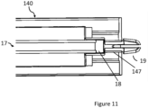
- the push rod (17) largely resides inside the graduated tube (16) with the reversible collapsible fitment means (19) of the pushrod (17) pushed in the pushrod passageway (147) such that the collar (18) of the pushrod (17) sits in the seat (146) of the carrier (140), Figure 11 .
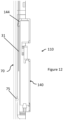
- the stem (33) of the IUD (30) sits in the graduated tube (16) at its IUD end (5), while the string (31) is slipped in and exits from the string exit slot (15) and is trapped between the string plug (144) and the string socket (75) while keeping it tautly pulled out from the hole (76), thus the string (31) is in the unreleased or the locked condition, Figure 12 .
- the terminating ends (35) of the string (31) are contained inside of the base (70) near its operator end (6).
- the knob (150) when the knob (150) is made to slide towards the IUD end (5), the graduated tube (16) and the dynamic stopper (20) also travel towards the IUD end (5).
- the dynamic stopper (20) travels forward by the sliding length (23) while the graduated tube (16) engulfs the arms of the IUD (30) till the edge (11) of the graduated tube (16) is stopped by the dome shaped ends (36) of the arms (34) having come almost together.
- Further sliding of the knob (150) towards the IUD end (5) causes the carrier (140) to also move towards the IUD end (5) due to the pusher (156) of the knob (150), and consequently the pushrod (17) also correspondingly moves.
- a movement of the carrier (140) towards the IUD end (5) causes the string plug (144) to move away and thus unplug from the string socket (75) and the string (31) is in an unlocked or a released condition, Figure 12A .
- the string management arrangement (110) in this embodiment therefore comprises the string plug (144) of the carriage (140) and the string socket (75) of the base (70); and locking and unlocking the string (31) takes place as described above.
- a background method (not forming part of the scope of protection but merely serving as background of the invention) to load the instrument (10) and safely place the IUD (30) in uterus (50) comprises the steps of:
- the medical service provider doesn't have to approximate intermediate stop and partial release of the IUD (30) as is prevalent in prior art products.
- the string management (110) comprises a floating cone (40) floatingly disposed on the graduated tube (16) and a tubeway (77) integratedly provided on the base (70).
- the floating cone (40) has a tubular hole (41) on an inside and a conical frustum (42) on an outside. There is provided a hook (43) on the IUD side (5) of the floating cone (40).
- the tube way (77) has an inner cylindrical path through which the graduated tube (16) passes clearly, while the floating cone (40) gets seated firmly in the tube way (77) like any known plug and a socket arrangement.
- the string (31) is wrapped around the hook (43) by several turns, slid through the tubular hole (41) and the tubeway (77) taut, while the floating cone (40) is firmly plugged in the tubeway (77).
- the instrument (10) when the knob is made to slide towards the IUD end (5), the graduated tube (16) travels towards the IUD end (5), while the floating cone (40) continues to remain plugged in the tubeway (77).
- the dynamic stopper (20) also travels by the sliding length (23) while the graduated tube (16) engulfs the arms (34) of the IUD (30) till the edge (11) of the graduated tube (16) is stopped by the dome shaped ends (36) of the arms (34) having come almost together.
- Further sliding of the knob (150) towards the IUD end (5) causes the carrier (140) to also move towards the IUD end (5), and consequently the pushrod (17) also correspondingly moves.
- the string (31) is unwrapped from over the hook (43) and the floating plug (40) gets plugged out, and the string (31) is in the unlocked or the released condition.
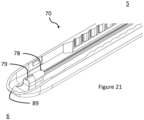
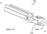
- the string management (110) comprises an extended receptacle (145) with an open side (145A) on the operator side (6) of the carrier (140), and an end plug (78) with a slit (79) integratedly provided on the operator end (6) of the base (70).
- the string (31) emerges out of the extended receptacle (145), taut, sits on the slit (79), and emerges out of an opening (89) of the base (70) while the extended receptacle (145) is firmly mounted on the end plug (78), keeping the string (31) in the locked condition.
- the operating knob (150) when the operating knob (150) is made to slide towards the IUD end (5), the graduated tube (16) travels towards the IUD end (5), while the carrier (140) and therefore the extended receptacle (145) continues to remain mounted on the end plug (78).
- the dynamic stopper (20) also travels by the sliding length (23) while the graduated tube (16) engulfs the arms (34) of the IUD (30) till the edge (11) of the graduated tube (16) is stopped by the dome shaped ends (36) of the arms (34) having come almost together. Further sliding of the operating knob (150) towards the IUD end (5) causes the carrier (140) to also move towards the IUD end (5), and consequently the pushrod (17) also correspondingly moves.
- the extended receptacle (145) now gets dismounted from the end plug (78), string (31) is untrapped from an in-between of the end plug (78) and the extended receptacle (145), and thus the string (31) is in the unlocked or the released condition.
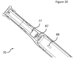
- FIG. 20 , 20A , 20B , 20C there is provided at least one outpoint (87) and one inpoint (88) on the floor (81) of the base (70).
- the outpoint (87) and the inpoint (88) is essentially a tapered hole.
- the string (31) exits from the outpoint (87) and re-enters from the inpoint (88).
- the string (31) is accessible to the medical service provider between the outpoint (87) and the inpoint (88) and the medical service provider has a preferred option to trim the string (31) as per sounding measurement of uterus of woman, BEFORE inserting the graduated tube (16) in the cervix thereby avoiding use of scissors or cutting tool (99) inside vaginal cavity, and this is most desired, safer and therefore preferred way of using the instrument (10) as per the present invention.
- the outpoint (87) is at a trim length (46) which is a minimum recommended excess string length expected to be hanging outside cervical os (51) in vaginal cavity of woman.
- the inpoint (88) is at a conservative length (47). Medical service provider has the freedom to trim the string (31) anywhere within the conservative length (47).
- a scale (48) is provided alongside to facilitate precision in trimming.
- the invention of string trimming before insertion is of significant benefit for instruments suited for all and any kind of IUD (30, 30A, 30B) and not limited to T-shaped IUD's, and this is an important ingredient of our invention.
- This ingredient of invention also implies that during release of the IUD (30, 30A, 30B), the instrument (10) handles much lesser length of string (31) than the prior art instruments wherein a long string (31) is always present till after release of IUD in uterus (50). It is known that a long string (31) has several occasions to undesirably interact with moving parts in the instrument (10) and may get entangled while withdrawing the IUD (30, 30A, 30B), and this possibility is completely obviated in our invention.
- the method to load the instrument (10) and safely place the IUD (30) in uterus (50) with above variations comprises the steps of:
- the base (70) has an out opening (89) through which the string (31) is still available to the medical service provider.
- the medical service provider can exercise the option to manually load the IUD (30) if that suits the service provider as per his or her previous experience or convenience.
- the push rod (17) has a longitudinal channel (12) or an equivalent construction to protect and shield the string (31) from getting entangled in the graduated tube (16).
- the instrument (10) operates from its either side, whether curvature up or curvature down, while maintaining a horizontal orientation.
Landscapes
- Health & Medical Sciences (AREA)
- Reproductive Health (AREA)
- Engineering & Computer Science (AREA)
- Biomedical Technology (AREA)
- Heart & Thoracic Surgery (AREA)
- Vascular Medicine (AREA)
- Life Sciences & Earth Sciences (AREA)
- Animal Behavior & Ethology (AREA)
- General Health & Medical Sciences (AREA)
- Public Health (AREA)
- Veterinary Medicine (AREA)
- Surgical Instruments (AREA)
- Endoscopes (AREA)
- Ultra Sonic Daignosis Equipment (AREA)
Description
- The present invention relates to an intra-uterine device, particularly to an instrument which is to load and insert the intra-uterine device and the process of loading, inserting and safely placing the intra-uterine device in the uterus of a woman, hygienically.
- There are several female contraceptives available. An intra-uterine device (herein after abbreviated as IUD) is a long-term or medium-term contraceptive which is placed in the uterus of female. Most commonly available IUDs are in the shape of the English letter "T" since this shape is found appropriate to the shape of uterus. While the IUDs are required to be in the shape of "T", they cannot be inserted in this form as the opening of the cervix is small. For this reason, all IUDs use an insertion instrument for insertion and proper location of the IUD. Arms forming "T" of IUD are folded either upwards or downwards so that IUD can be contained in the opening of a narrow tube/inserter which then can be inserted in the uterus. This process of folding the IUD so that the instrument/inserter is ready to insert is known as loading or preparing the IUD.
- Loading or preparing of IUD needs to be done minutes before it is required to be inserted in uterus, and if done earlier, or if supplied duly loaded, then the IUD shall not return to the desired "T" shape in uterus and shall not work effectively. Due to this requirement, the process of loading has to be performed by service providers just prior to inserting and placing IUD in uterus.
- Up-folding IUDs and down-folding IUD have a significant difference in their preparation and placement procedure. Upfolding IUDs implies that arms forming "T" are together while stem of IUD is below folded arms. This may be easily understood from Figures 1A to 3B of Patent
US5785053A . Patent applicationUS2013/0014762(A1 ) also comprehensively covers an upfolding IUD. Down-folding implies that arms forming "T" as well as stem of IUD are together. This may be easily understood fromFigures 7 and9 of PatentUS4143656 . - There is a significant difference in process of inserting and placing an up-folding IUD and a down-folding IUD in uterus. While placing an upfolding IUD, the arms of the "T" start unfolding downwards as soon as IUD is made to gradually eject out of the instrument. Person placing such upfolding IUD takes a pause to allow the upfolding arms to unfold at their own pace before finally placing IUD in uterus, lest ends of arms of IUD gets entangled with side walls of uterus, preventing a far end of IUD to reach fundus! On the other hand, when placing a downfolding IUD, there is no such precaution needed as the arms of IUD unfold upwards at their own natural pace while a far end of the IUD touches fundus.
- In other words, an upfolding IUD is easier to load and difficult to place in uterus, while a downfolding IUD is relatively more difficult to load and relatively easier to place.
- Patent application number
US15745579 US 2018/0055684 A1 , on the other hand discloses another instrument suitable for upfolding IUDs. - Prior art like
US 10028858 US2019/0307600 continue to ignore that a string attached to the IUD substantially stays in the instrument when the IUD is just placed in the uterus and the instrument is being withdrawn. Therefore, string entangling in the instrument remains a potential cause of disturbing safe placement of IUD in the uterus. Importantly, it is left to the service provider to randomly stop intermittently while inserting an upfolded IUD! - Such instruments being for one-time use, cost is an important factor.
- Present invention effectively and economically addresses loading or preparation of upfolding IUDs for subsequent insertion and safe placement in uterus.
- The closest prior art to the present invention is
WO 2012/055766 which discloses an inserter for inserting and positioning an intra-uterine device (IUD) which is attached to a withdrawal string, said inserter comprising: a plunger, a handle attached to the plunger and a longitudinal member that forms part of the handle. - The objective is to invent an instrument to load or prepare an intra-uterine device hygienically.
- Another objective is to invent a simple instrument to load or prepare an intra-uterine device which is upfoldable.
- Yet another objective is to invent an instrument which is capable of loading the intra uterine device in a consistent manner.
- Yet another objective is to invent an instrument that causes minimal trauma to woman.
- Yet another objective is to invent an instrument that ensures a horizontal orientation of the IUD, while the instrument may operate from an either horizontal orientation.
- Yet another objective is to ensure suture release mechanism that ensures that the suture/thread/string is never stuck anywhere after deployment.
- Yet another objective is to ensure single hand operation for insertion, deployment and retraction steps of the instrument.
- Yet another objective is to ensure prevent accident or injury during insertion in any case to avoid perforation of fundus.
- Yet another objective is to invent an instrument which is economical and effective.
- Yet another objective is to achieve multiple stages of complete process with a single hand and knob movement.
- Yet another objective is to eliminate and or minimize the guesswork of the user in complete operation while preparing/loading, deployment/release.
- Yet another objective is to prepare string length prior to insertion, according to uterus size of woman.
- The instrument according to present invention comprises a "T" shaped intra-uterine device, a graduated tube, a push rod inside the graduated tube, a dynamic stopper with a flange, operated by an operating device. The instrument further comprises a string management arrangement. The string of the IUD is in an unreleased or a locked condition, and taut between the lower end and the operating arrangement, when the instrument is received by a medical service provider. In the present invention, the string is NOT required to be pulled/manipulated by the medical service provider for loading or preparing the instrument. The process of loading, inserting in uterus and safely releasing the IUD is carried out by a single hand operation.
- The dynamic stopper is a tubular channel having the flange. There are provided guide paths at least on two alternate faces of the dynamic stopper. A sliding length of the dynamic stopper is commensurate with an arm length of the arms of the IUD. A diameter of the tubular channel allows a passage of the graduated tube tightly.
- The operating device comprises a base, a cover, an operating knob, a carriage. The base has an open neck construction with a collar and a first flange guiding projections. There are carrier guiding projections. On an inside of walls is provided an array of continuous incline and notches alternately for a prescribed length. There are a plurality of cover engagement means on both the walls. A tube guideway, also provided is a string socket with a hole. The base is slightly curvatured.
- The carriage has at least a pair of locking tooth on an either side. The travel slot has an assembly opening which is wider than the travel slot. There is provided a string plug on a lower side. At the operator end of the instrument is a pushrod passageway with a seat.
- The operating knob has a thumb surface and at least a pointer on an either knob side. There is provided a hanging tubular construction on an opposite side of the thumb surface. The tubular construction has a larger diameter part having a pair of pusher, and a smaller diameter part.
- The cover has a slot, an open complementing neck construction, a second flange guiding projections, and a plurality of base engagement means equal in number of the cover engagement means. A knob markings are provided on an external side of the cover. The cover is slightly curvature in accordance with the base.
- The pushrod is a slender cylinder, has a collar, a reversibly collapsible fitment means at its operator end and a flat surface at the IUD end.
- The graduated tube is a thin walled hollow cylinder having an edge at the IUD end, a measurement markings and a string exit slot.
- In the instrument that is ready to use, the dynamic stopper slidably resides in the base free to slide along the guide paths constrained by the first flange guiding projections and or the second flange guiding projections, and can slide by the sliding length. The operator end of the graduated tube is slided with a little force through the tubular channel of the dynamic stopper, till the operator end of the graduated tube is disposed firmly in the larger diameter part of the knob. The dynamic stopper rides on the graduated tube. The hanging tubular construction of knob resides in the travel slot of the carrier. The push rod largely resides inside the graduated tube with the reversible collapsible fitment means of the pushrod pushed in the pushrod passageway such that the collar of the pushrod sits in the seat of the carrier. The stem of the IUD sits in the graduated tube at its IUD end, while the string is slipped in and exits from the string exit slot and is trapped between the string plug and the string socket while keeping it tautly pulled out from the hole, thus the string is in the unreleased or the locked condition. The terminating ends of the string are contained inside of the base near its operator end.
- For use of the instrument, when the knob is made to slide towards the IUD end, the graduated tube and the dynamic stopper also travel towards the IUD end. The dynamic stopper travels forward by the sliding length while the graduated tube engulfs the arms of the IUD till the edge of the graduated tube is stopped by the dome shaped ends of the arms having come almost together. Further sliding of the knob towards the IUD end causes the carrier to also move towards the IUD due to the pusher of the knob, and consequently the pushrod also correspondingly moves. A movement of the carrier towards the IUD end causes the string plug to move away and thus unplug from the string socket and the string is in an unlocked or a released condition.
- Importantly, due to the inventive dynamic stopper that moves equivalent to arm length, the medical service provider doesn't have to approximate intermediate stop and partial release of the IUD as is prevalent in prior art products.
- In another embodiment, the string management comprises a floating cone floatingly disposed on the graduated tube and a tubeway integratedly provided on the base.
- The floating cone has a tubular hole on an inside and a conical frustum on an outside. There is provided a hook on the IUD side of the floating cone. The tube way has an inner cylindrical path through which the graduated tube passes clearly, while the floating cone gets seated firmly in the tube way like any known plug and a socket arrangement.
- In the instrument as per second embodiment that is ready to use, the string is wrapped around the hook by several turns, slid through the tubular hole and the tubeway taut, while the floating cone is firmly plugged in the tubeway.
- For use of the instrument as per second embodiment, when the knob made to slide towards the IUD end causes the carrier to also move the string is then unwrapped from over the hook and the floating plug gets plugged out, and the string is in the unlocked or the released condition.
- In yet another embodiment, the string management comprises an extended receptacle with an open side on the operator side of the carrier, and an end plug with a slit integratedly provided on the operator end of the base.
- In the instrument as per third embodiment that is ready to use, the string emerges out of the extended receptacle, taut, sits on the slit, and emerges out of an opening of the base while the extended receptacle is firmly mounted on the end plug, keeping the string in the locked condition.
- For use of the instrument as per third embodiment, when the operating knob causes the carrier to also move towards the IUD end, the extended receptacle gets dismounted from the end plug, string is untrapped from an in-between of the end plug and the extended receptacle, and thus the string is in the unlocked or the released condition.
- There is provided at least one outpoint and one inpoint on the floor of the base. The outpoint and the inpoint is essentially a tapered hole. The string exits from the outpoint and re-enters from the inpoint. The string is accessible to the medical service provider between the outpoint and the inpoint and the medical service provider has a preferred option to trim the string as per sounding measurement of uterus of woman, BEFORE inserting the graduated tube in the cervix thereby avoiding use of scissors or cutting tool inside vaginal cavity. The outpoint is at a trim length which is a minimum recommended excess string length expected to be hanging outside cervical os in vaginal cavity of woman. The inpoint is at a conservative length. Medical service provider has the freedom to trim the string anywhere within the conservative length. A scale is provided alongside to facilitate precision in trimming.
- When the medical service provider uses the option of trimming the string before insertion, the method to load the instrument and safely place the IUD in uterus with above variations comprises the steps of:
- a) Sounding a uterus of woman and determining a uterine depth,
- b) Sliding the operating knob towards an IUD end till the arms of the IUD are folded and fully contained in the graduated tube,
- c) Sliding the operating knob further towards the IUD end till the graduated tube projects out by a length of the uterine depth , judging by hearing an audible clicking sound produced due to the pair of locking tooth negotiating with the array of inclines and notches or judging by the measurement markings on the graduated tube aligning with the flange or by the position of the pointer of the operating knob at the knob markings on the cover,
- d) Trimming an excess length of the strings of the IUD anywhere in the conservative length,
- e) Inserting the graduated tube in the uterus till the flange touches cervical os of the uterus,
- f) Sliding back the operating knob till the dynamic stopper retracts by the sliding length and stops,
- g) Further inserting the graduated tube in the uterus till the flange of retracted dynamic stopper again touches the cervical os,
- h) Sliding back the operating knob as much as possible, and
- i) Taking out the graduated tube from woman.
- As another variation, the base has an out opening through which the string is still available to the medical service provider. The medical service provider can exercise the option to manually load the IUD if that suits the service provider as per his or her previous experience or convenience.
- As yet another variation the push rod has a longitudinal channel or an equivalent construction to protect and shield the string from getting entangled in the graduated tube.
- The instrument operates from its either side, whether curvature up or curvature down, while maintaining a horizontal orientation.
-
-
Figure 1 is a perspective view of an instrument as per present invention. -
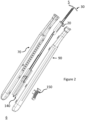
Figure 2 is an exploded view of the present invention. -
Figure 3 are front views of an IUD with its arms unfolded (almost horizontal) and folded (almost vertical). -
Figure 4 are perspective views of a dynamic stopper. -
Figure 5 is a perspective view of a base with enlarged views of encircled portion of the base. -
Figure 6 is a perspective view of a cover whileFigure 6A is another perspective view with enlarged view of encircled portion of the cover. -
Figure 7 is a perspective view and a sectional view of an operating knob. -
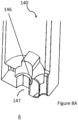
Figure 8 are two perspective views of a carrier whileFigure 8A is a partial sectional view of the carrier. -
Figure 9 is a perspective view of a push rod with an enlarged view of its encircled portion. -
Figure 10 is a perspective view of a graduated tube with an enlarged view of its encircled portion. -
Figure 11 is a partial sectional side view of the carrier and the push rod engaged therein. -
Figure 12 is a sectional view of a first embodiment of a string management arrangement with a string unlocked, whileFigure 12A is a sectional view showing the string locked. -
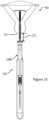
Figure 13 is a front view of the instrument with the graduated tube extended in accordance with uterine depth of uterus. -
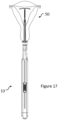
Figures 14 to 18 are front views of steps of insertion and safe release of the IUD in uterus. -
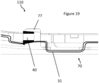
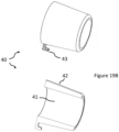
Figure 19 and19A is a sectional view of a second embodiment of the string management arrangement with the string locked,Figure 19A is a sectional view with the string unlocked, whileFigure 19B is a perspective view and a sectional view of a floating cone. -
Figure 20 ,20A and20B , are views showing string trimming arrangement after loading but before insertion of IUD, whileFigure 20C shows string trimming arrangement for different kinds of IUDs. -
Figures 21 ,21A are perspective views of the base and the carrier, whileFigures 21B and21C are partial sectional views of a third embodiment of the string management arrangement. -
Figure 22 is a perspective view of the push rod as per another embodiment. - The present invention of an instrument to load and insert an upfoldable intra-uterine device and process thereof will now be described with reference to the accompanying drawings. It is to be understood that the description explains the preferred embodiments and several ways are possible around the invention. Apropos, the description should not be construed to limit the invention in any way whatsoever. The terms and expressions which have been used here are merely for description and not for limitation. The term "preparing" and "loading" are used interchangeably.
-
Figure 1 ,2 the instrument (10) according to present invention comprises a "T" shaped intra-uterine device (30), a graduated tube (16), a push rod (17) inside the graduated tube (16), a dynamic stopper (20) with a flange (25), operated by an operating device (100). The instrument (10) further comprises a string management arrangement (110), shown inFigures 12 and12A being one of the embodiments. The preferred embodiment is around the IUD (30) generally comprising a frame having two arms (34) and a stem (33), with both arms (34) of the IUD (30) foldable away from the stem (33) of the IUD (30), as shown inFigure 3 . The instrument (10) is shipped in this position when the IUD (30) is with its arms (34) in a "T" formation with respect to the stem (33), as it should be when placed in uterus of woman. The IUD (30) further comprises a contraceptive material (49) disposed around the stem (33), and at least one string (31) emerges from a lower end (37) of the stem (33). The string (31) has a terminating ends (35). The string (31) of the IUD (30) is in an unreleased or a locked condition, and taut between the lower end (37) and the operating arrangement (110), when the instrument (10) is received by a medical service provider. In the present invention, the string (31) is NOT required to be pulled/manipulated by the medical service provider for loading or preparing the instrument (10), and the loading/preparing method is described below. Apropos, the terminating ends (35) of the string (31) can be concealed in the operating device (100) and may or may not be visible/accessible to medical service provider. - As shall be evident, the process of loading, inserting in uterus and safely releasing the IUD (30) is caried out by a single hand operation, and it is of great benefit to the medical service provider. An IUD end (5) and an operator end (6) signifies direction of the instrument (10) and all parts while describing features, sub-assembly, assembly and method of use.
-
Figure 4 , the dynamic stopper (20) is a tubular channel (22) having the flange (25) at the IUD end (5) of the dynamic stopper (20) and a non-circular outer face of lesser mating perimeter than that of the flange (25). There are provided guide paths (21) at least on two alternate faces of the dynamic stopper (20). A sliding length (23) of the dynamic stopper (20) is commensurate with an arm length (38) of the arms (34) of the IUD (30). A face distance (26) of the regular hexagonal channel (22) permits multi-point contacts on the graduated tube (16) and allows a passage of the graduated tube (16) tightly. -
Figure 2 , the operating device (100) comprises - a base (70)
- a cover (90)
- an operating knob (150)
- a carriage (140)
-
Figure 5 , the base (70) has two parallel walls (80) a floor (81), an open neck construction (73) with a collar (71) and a first flange guiding projections (72) at its IUD end (5) of each wall (80) or on the floor (81). There are carrier guiding projections (73) on the floor (81). On an inside of the walls (80) is provided an array of continuous incline and notches (82) alternately for a prescribed length (83). There are a plurality of cover engagement means (74) on both the walls (80). A tube guideway (84) is provided on the floor (81). Also provided is a string socket (75) with a hole (76). The base (70) is slightly curvatured. -
Figure 8 ,8A , the carriage (140) has a travel slot (143) on an upper side (141), at least a pair of locking tooth (148) on an either carrier (140) side. The travel slot (143) has an assembly opening (143A) which is wider than the travel slot (143). On the lower side (142) is a travel surface (149). There is provided a string plug (144) on the lower side (142). At the operator end (6) is a pushrod passageway (147) with a seat (146). -
Figure 7 , the operating knob (150) has a thumb surface (159), and at least a pointer (158) on an either knob side. There is provided a hanging tubular construction (152) on an opposite side (158) of the thumb surface (159). The tubular construction (152) has a larger diameter part (153) having a pair of pusher (156), and a smaller diameter part (154). -
Figure 6 ,6A , the cover (90) has a slot (91), an open complementing neck construction (93), a second flange guiding projections (92), and a plurality of base engagement means (94) equal in number of the cover engagement means (74). A knob markings (95) are provided on an external side (96) of the cover (90). The cover (90) is slightly curvature in accordance with the base (70).Figure 9 , the pushrod (17) is a slender cylinder, has a collar (18), a reversibly collapsible fitment means (19) at its operator end (6) and a flat surface (13) at the IUD end (5). -
Figure 10 , the graduated tube (16) is a thin walled hollow cylinder having an edge (11) at the IUD end (5), a measurement markings (14) and a string exit slot (15). - In the instrument (10) that is ready to use, the dynamic stopper (20) slidably resides in the base (70) free to slide along the guide paths (21) constrained by the first flange guiding projections (72) and or the second flange guiding projections (92), and can slide by the sliding length (23). The operator end (6) of the graduated tube (16) is slided with a little force through the tubular channel (22) of the dynamic stopper (20), till the operator end (6) of the graduated tube (16) is disposed firmly in the larger diameter part (153) of the knob (150). The dynamic stopper (20) rides on the graduated tube (16). The hanging tubular construction (152) of knob (150) resides in the travel slot (143) of the carrier (140). The push rod (17) largely resides inside the graduated tube (16) with the reversible collapsible fitment means (19) of the pushrod (17) pushed in the pushrod passageway (147) such that the collar (18) of the pushrod (17) sits in the seat (146) of the carrier (140),
Figure 11 . The stem (33) of the IUD (30) sits in the graduated tube (16) at its IUD end (5), while the string (31) is slipped in and exits from the string exit slot (15) and is trapped between the string plug (144) and the string socket (75) while keeping it tautly pulled out from the hole (76), thus the string (31) is in the unreleased or the locked condition,Figure 12 . The terminating ends (35) of the string (31) are contained inside of the base (70) near its operator end (6). - For use of the instrument (10), when the knob (150) is made to slide towards the IUD end (5), the graduated tube (16) and the dynamic stopper (20) also travel towards the IUD end (5). The dynamic stopper (20) travels forward by the sliding length (23) while the graduated tube (16) engulfs the arms of the IUD (30) till the edge (11) of the graduated tube (16) is stopped by the dome shaped ends (36) of the arms (34) having come almost together. Further sliding of the knob (150) towards the IUD end (5) causes the carrier (140) to also move towards the IUD end (5) due to the pusher (156) of the knob (150), and consequently the pushrod (17) also correspondingly moves. A movement of the carrier (140) towards the IUD end (5) causes the string plug (144) to move away and thus unplug from the string socket (75) and the string (31) is in an unlocked or a released condition,
Figure 12A . - The string management arrangement (110) in this embodiment therefore comprises the string plug (144) of the carriage (140) and the string socket (75) of the base (70); and locking and unlocking the string (31) takes place as described above.
-
Figures 13-18 , a background method (not forming part of the scope of protection but merely serving as background of the invention) to load the instrument (10) and safely place the IUD (30) in uterus (50) comprises the steps of: - a) Sounding a uterus of woman and determining a uterine depth (45)
- b) Sliding the operating knob (150) towards an IUD end (5) till the arms (34) of the IUD (30) are folded and fully contained in the graduated tube (16),
- c) Sliding the operating knob (150) further towards the IUD end (5) till the graduated tube (16) projects out by a length of the uterine depth (45), judging by hearing an audible clicking sound produced due to the pair of locking tooth (143) negotiating with the array of inclines and notches (82) or judging by the measurement markings (14) on the graduated tube (16) aligning with the flange (25) or by the position of the pointer (158) of the operating knob (150) at the knob markings (95) on the cover (90),
- d) Inserting the graduated tube (16) in the uterus (50) till the flange (25) touches cervical os (51) of the uterus (50),
- e) Sliding back the operating knob (150) till the dynamic stopper (20) retracts by the sliding length (23) and stops,
- f) Further inserting the graduated tube (16) in the uterus (50) till the flange (25) of retracted dynamic stopper (20) again touches the cervical os (51)
- g) Sliding back the operating knob (150) as much as possible,
- h) Taking out the graduated tube (16) from woman, and
- i) Trimming an excess length of the strings (31) of the IUD (30).
- Importantly, due to the inventive dynamic stopper (20) that moves equivalent to arm length (38), the medical service provider doesn't have to approximate intermediate stop and partial release of the IUD (30) as is prevalent in prior art products.
-
Figures 19 ,19A ,19B ,20 , in another embodiment, the string management (110) comprises a floating cone (40) floatingly disposed on the graduated tube (16) and a tubeway (77) integratedly provided on the base (70). - The floating cone (40) has a tubular hole (41) on an inside and a conical frustum (42) on an outside. There is provided a hook (43) on the IUD side (5) of the floating cone (40). The tube way (77) has an inner cylindrical path through which the graduated tube (16) passes clearly, while the floating cone (40) gets seated firmly in the tube way (77) like any known plug and a socket arrangement.
- In the instrument (10) as per second embodiment that is ready to use, the string (31) is wrapped around the hook (43) by several turns, slid through the tubular hole (41) and the tubeway (77) taut, while the floating cone (40) is firmly plugged in the tubeway (77).
- For use of the instrument (10) as per second embodiment, when the knob is made to slide towards the IUD end (5), the graduated tube (16) travels towards the IUD end (5), while the floating cone (40) continues to remain plugged in the tubeway (77). The dynamic stopper (20) also travels by the sliding length (23) while the graduated tube (16) engulfs the arms (34) of the IUD (30) till the edge (11) of the graduated tube (16) is stopped by the dome shaped ends (36) of the arms (34) having come almost together. Further sliding of the knob (150) towards the IUD end (5) causes the carrier (140) to also move towards the IUD end (5), and consequently the pushrod (17) also correspondingly moves. The string (31) is unwrapped from over the hook (43) and the floating plug (40) gets plugged out, and the string (31) is in the unlocked or the released condition.
-
Figures 21 ,21A ,21B ,21C , in yet another embodiment, the string management (110) comprises an extended receptacle (145) with an open side (145A) on the operator side (6) of the carrier (140), and an end plug (78) with a slit (79) integratedly provided on the operator end (6) of the base (70). - In the instrument (10) as per third embodiment that is ready to use, the string (31) emerges out of the extended receptacle (145), taut, sits on the slit (79), and emerges out of an opening (89) of the base (70) while the extended receptacle (145) is firmly mounted on the end plug (78), keeping the string (31) in the locked condition.
- For use of the instrument (10) as per third embodiment, when the operating knob (150) is made to slide towards the IUD end (5), the graduated tube (16) travels towards the IUD end (5), while the carrier (140) and therefore the extended receptacle (145) continues to remain mounted on the end plug (78). The dynamic stopper (20) also travels by the sliding length (23) while the graduated tube (16) engulfs the arms (34) of the IUD (30) till the edge (11) of the graduated tube (16) is stopped by the dome shaped ends (36) of the arms (34) having come almost together. Further sliding of the operating knob (150) towards the IUD end (5) causes the carrier (140) to also move towards the IUD end (5), and consequently the pushrod (17) also correspondingly moves. The extended receptacle (145) now gets dismounted from the end plug (78), string (31) is untrapped from an in-between of the end plug (78) and the extended receptacle (145), and thus the string (31) is in the unlocked or the released condition.
-
Figure 20 ,20A ,20B ,20C , there is provided at least one outpoint (87) and one inpoint (88) on the floor (81) of the base (70). The outpoint (87) and the inpoint (88) is essentially a tapered hole. The string (31) exits from the outpoint (87) and re-enters from the inpoint (88). The string (31) is accessible to the medical service provider between the outpoint (87) and the inpoint (88) and the medical service provider has a preferred option to trim the string (31) as per sounding measurement of uterus of woman, BEFORE inserting the graduated tube (16) in the cervix thereby avoiding use of scissors or cutting tool (99) inside vaginal cavity, and this is most desired, safer and therefore preferred way of using the instrument (10) as per the present invention. The outpoint (87) is at a trim length (46) which is a minimum recommended excess string length expected to be hanging outside cervical os (51) in vaginal cavity of woman. The inpoint (88) is at a conservative length (47). Medical service provider has the freedom to trim the string (31) anywhere within the conservative length (47). A scale (48) is provided alongside to facilitate precision in trimming. - It is to be noted that the invention of string trimming before insertion is of significant benefit for instruments suited for all and any kind of IUD (30, 30A, 30B) and not limited to T-shaped IUD's, and this is an important ingredient of our invention. This ingredient of invention also implies that during release of the IUD (30, 30A, 30B), the instrument (10) handles much lesser length of string (31) than the prior art instruments wherein a long string (31) is always present till after release of IUD in uterus (50). It is known that a long string (31) has several occasions to undesirably interact with moving parts in the instrument (10) and may get entangled while withdrawing the IUD (30, 30A, 30B), and this possibility is completely obviated in our invention.
- When the medical service provider uses the option of trimming the string (31) before insertion, the method to load the instrument (10) and safely place the IUD (30) in uterus (50) with above variations comprises the steps of:
- a) Sounding a uterus (50) of woman and determining a uterine depth (45)
- b) Sliding the operating knob (150) towards an IUD end (5) till the arms of the IUD (30) are folded and fully contained in the graduated tube (16),
- c) Sliding the operating knob (150) further towards the IUD end (5) till the graduated tube (16) projects out by a length of the uterine depth (45), judging by hearing an audible clicking sound produced due to the pair of locking tooth (143) negotiating with the array of inclines and notches (82) or judging by the measurement markings (14) on the graduated tube (16) aligning with the flange (25) or by the position of the pointer (158) of the operating knob (150) at the knob markings (95) on the cover (90),
- d) Trimming an excess length of the strings (31) of the IUD (30) anywhere in the conservative length (47),
- e) Inserting the graduated tube (16) in the uterus (50) till the flange (25) touches cervical os (51) of the uterus (50)
- f) Sliding back the operating knob (150) till the dynamic stopper (20) retracts by the sliding length (23) and stops,
- g) Further inserting the graduated tube (16) in the uterus (50) till the flange (25) of retracted dynamic stopper (20) again touches the cervical os (51)
- h) Sliding back the operating knob (150) as much as possible, and
- i) Taking out the graduated tube (16) and the instrument (10) from woman.
-
Figure 21 , as another variation, the base (70) has an out opening (89) through which the string (31) is still available to the medical service provider. The medical service provider can exercise the option to manually load the IUD (30) if that suits the service provider as per his or her previous experience or convenience. -
Figure 22 , as yet another variation the push rod (17) has a longitudinal channel (12) or an equivalent construction to protect and shield the string (31) from getting entangled in the graduated tube (16). - The invention as described above can be worked with a permutation and combination of embodiments described above and the variations described are not mutually exclusive in any particular group or formation.
- The instrument (10) operates from its either side, whether curvature up or curvature down, while maintaining a horizontal orientation.
Claims (12)
- An instrument (10) configured to prepare and safely place an intra-uterine device (30) in uterus (50) of a woman, the instrument (10) comprising a "T" shaped intra-uterine device (IUD) (30) with both arms (34) foldable away from a stem (33) of the IUD (30), a graduated tube (16), a push rod (17) inside the graduated tube (16), wherein the instrument (10) comprises:a dynamic stopper (20) with a tubular channel (22) and a flange (25), wherein a sliding length (23) of the dynamic stopper (20) is commensurate with an arm length (38) of the arms (34) of the IUD (30);a string management arrangement (110) whereby a string (31) of the IUD (30) is in one of a locked condition or an unlocked condition;an operating device (100), further comprising:a base (70) having an array of continuous incline and notches (82) alternately for a prescribed length (83), a plurality of cover engagement means (74), a tube guideway (84), a first flange guiding projections (72), a carrier guiding projections (73),a cover (90) having a slot (91), a plurality of base engagement means (94) equal in number of the cover engagement means (74), a knob (150), a knob markings (95),a carriage (140) having a travel slot (143), at least a pair of locking tooth (148) on an either carrier side, a pushrod passageway (147) with a seat (146),an operating knob (150) having at least a pointer (158), a hanging tubular construction (152) with a larger diameter part (153) along with a pusher (156) and a smaller diameter part (154),the pushrod (17) has a collar (18) and a reversibly collapsible fitment means (19) at its operator end (6) and a flat surface (13) at the IUD end (5), andthe graduated tube (16) having an edge (11) at the IUD end (5), a measurement markings (14) and a string exit slot (15);wherein the dynamic stopper (20) slidably resides in the base (70) and can slide by the sliding length (23), an operator end (6) of the graduated tube (16) is slided through the tubular channel (22) of the dynamic stopper (20), till the operator end (6) of the graduated tube (16) is disposed firmly in the larger diameter part (153) of the knob (150), the dynamic stopper (20) rides on the graduated tube (16), the hanging tubular construction (152) of knob (150) resides in the travel slot (143) of the carrier (140), the push rod (17) resides inside the graduated tube (16) with the reversibly collapsible fitment means (19) of the pushrod (17) pushed in the pushrod passageway (147) such that the collar (18) of the pushrod (17) sits in the seat (146) of the carrier (140); andwhen the knob (150) is made to slide towards the IUD end (5), the graduated tube (16) and the dynamic stopper (20) also travel towards the IUD end (5), the dynamic stopper (20) travels by the sliding length (23) while the graduated tube (16) engulfs the arms of the IUD till the edge (11) of the graduated tube (16) is stopped by the dome shaped ends (36) of the arms (34) while the string (31) remains in the locked condition, a further sliding of the knob (150) towards the IUD end (5) causes the carrier (140) to also move towards the IUD end (5), the pushrod (17) correspondingly moves while the string (31) is in the unlocked condition, a forward and a backward movement of the operating knob (150) by a sliding force on a thumb surface (159), the instrument (10) configured for a single hand grip as well as configured to move the knob (150) by a thumb of the same hand.
- The instrument (10) configured to prepare and safely place an intra-uterine device (30) as claimed in claim 1, wherein the string management arrangement (110) comprises a string plug (144) of the carriage (140) and a string socket (75) with a hole (76) on the base (70), the instrument (10) that is ready to use has the string (31) passed through the hole (76), taut, the string plug (144) plugged into the string socket (75), the string therefore is in the locked condition; a movement of the carrier (140) towards the IUD end (5) causes the string plug (144) to move away and unplug from the string socket (75), the string (31) consequently is in the unlocked condition.
- The instrument (10) configured to prepare and safely place an intra-uterine device (30) as claimed in claim 1, wherein the string management (110) comprises a floating cone (40) floatingly disposed on the graduated tube (16) and a tubeway (77) integratedly provided on the base (70),wherein the floating cone (40) has a tubular hole (41) on an inside and a conical frustum (42) on an outside, a hook (43) on the IUD side (5) of the floating cone (40), while the tube way (77) has an inner cylindrical path through which the graduated tube (16) passes clearly,the instrument (10) that is ready to use has the string wrapped around the hook (43), slid through the tubular hole (41) and the tubeway (77) taut, while the floating cone (40) is firmly plugged in the tubeway (77), the string (31) in the locked condition, andwhen the knob (150) is made to slide towards the IUD end (5), the floating cone (40) continues to remain plugged in the tubeway (77), a further sliding of the knob (150) towards the IUD end (5) causes the carrier (140) to also move towards the IUD end (5), and consequently the pushrod (17) also correspondingly moves, the string (31) is unwrapped from over the hook (43) and the floating cone (40) gets plugged out, and the string (31) is in the unlocked condition.
- The instrument (10) configured to prepare and safely place an intra-uterine device (30) as claimed in claim 1, wherein the string management (110) comprises an extended receptacle (145) with an open side (145A) on the operator side (6) of the carrier (140), and an end plug (78) with a slit (79) integratedly provided on the operator end (6) of the base (70), in the instrument (10) ready to use, the string (31) emerges out of the extended receptacle (145), taut, sits on the slit (79), and emerges out of an opening (89) of the base (70) while the extended receptacle (145) is firmly mounted on the end plug (78), keeping the string (31) in the locked condition; a movement of the carrier (140) towards the IUD end (5) causes the extended receptacle (145) to move away and dismount from the end plug (78), the string (31) is consequently in the unlocked condition.
- The instrument (10) configured to prepare and safely place an intra-uterine device (30) as claimed in claim 1, wherein the base (70) has at least one outpoint (87) and one inpoint (88), wherein the string (31) exits from the outpoint (87) and re-enters from the inpoint (88).
- The instrument (10) configured to prepare and safely place an intra-uterine device (30) as claimed in claim 5, wherein the outpoint (87) is at a trim length (46) which is a minimum recommended excess string (31) length configured to be hanging outside a cervical os (51) in vaginal cavity of woman.
- The instrument (10) configured to prepare and safely place an intra-uterine device (30) as claimed in claim 5, wherein the inpoint (88) is at a conservative length (47), and wherein the outpoint (87) and the inpoint (88) have a scale (48) alongside.
- The instrument (10) configured to prepare and safely place an intra-uterine device (30) as claimed in claim 5, wherein the base (70) is curvatured, and the cover (90) is curvatured correspondingly.
- The instrument (10) configured to prepare and safely place an intra-uterine device (30) as claimed in claim 1, wherein the dynamic stopper (20) further comprises a non-circular outer faces of lesser mating perimeter than that of the flange (25), there are provided guide paths (21) at least on two alternate faces of the dynamic stopper (20), wherein a face distance (26) of the tubular channel (22) permits a multi-point contacts on the graduated tube (16) and allows a passage of the graduated tube (16) tightly.
- The instrument (10) configured to prepare and safely place an intra-uterine device (30) as claimed in claim 1, wherein the carriage (140) further comprises a knob assembly opening (143A) which is wider than the travel slot (143), on the lower side (142) is a travel surface (149).
- The instrument (10) configured to prepare and safely place an intra-uterine device (30) as claimed in claim 1, wherein the base (70) has an out opening (89) through which a terminating ends (35) of the string (31) emerge out.
- The instrument (10) configured to prepare and safely place an intra-uterine device (30) as claimed in claim 1, wherein the push rod (17) has a longitudinal channel (12) along a length (17A) of the push rod (17).
Applications Claiming Priority (1)
| Application Number | Priority Date | Filing Date | Title |
|---|---|---|---|
| IN202021041234 | 2020-09-23 |
Publications (3)
| Publication Number | Publication Date |
|---|---|
| EP3973930A2 EP3973930A2 (en) | 2022-03-30 |
| EP3973930A3 EP3973930A3 (en) | 2022-06-15 |
| EP3973930B1 true EP3973930B1 (en) | 2024-09-25 |
Family
ID=77398507
Family Applications (1)
| Application Number | Title | Priority Date | Filing Date |
|---|---|---|---|
| EP21191988.1A Active EP3973930B1 (en) | 2020-09-23 | 2021-08-18 | An instrument to prepare and safely place an intra-uterine device |
Country Status (2)
| Country | Link |
|---|---|
| US (1) | US11963904B2 (en) |
| EP (1) | EP3973930B1 (en) |
Families Citing this family (1)
| Publication number | Priority date | Publication date | Assignee | Title |
|---|---|---|---|---|
| US11969377B2 (en) * | 2021-10-27 | 2024-04-30 | Pregna International Limited | Single-use instrument to prepare and safely place an intra-uterine device |
Family Cites Families (8)
| Publication number | Priority date | Publication date | Assignee | Title |
|---|---|---|---|---|
| NL7802043A (en) | 1977-03-28 | 1978-10-02 | Ortho Pharma Corp | INSTRUMENT FOR THE INSERTION OF AN INTRA-UTERINE ANTI-CONCEPTION AGENT AND A METHOD FOR THE INSERTION OF AN INTRA-UTERINE ANTI-CONCEPTION AGENT. |
| FI97946C (en) | 1994-12-15 | 1997-03-25 | Leiras Oy | Depositor intended for setting up a device for intrauterine use |
| DE29919662U1 (en) * | 1999-11-09 | 2000-02-03 | Riek, Siegfried, Dr.med., 78628 Rottweil | Introducer for the insertion of an intrauterine contraceptive device |
| PT2632399E (en) * | 2010-10-29 | 2015-03-16 | Odyssea Pharma S P R L | Intra-uterine insertion device |
| US10028858B2 (en) | 2011-07-11 | 2018-07-24 | Medicines360 | Intrauterine systems, IUD insertion devices, and related methods and kits therefor |
| US11278445B2 (en) * | 2015-07-30 | 2022-03-22 | Medicines360 | IUD loading devices and methods for inserting an IUD into an insertion device |
| US10918517B2 (en) | 2016-08-27 | 2021-02-16 | Meril Endo Surgery Pvt. Ltd. | Intrauterine device inserter |
| US11571328B2 (en) | 2018-04-09 | 2023-02-07 | Medicines360 | IUD insertion devices |
-
2021
- 2021-08-13 US US17/401,837 patent/US11963904B2/en active Active
- 2021-08-18 EP EP21191988.1A patent/EP3973930B1/en active Active
Also Published As
| Publication number | Publication date |
|---|---|
| US20220087856A1 (en) | 2022-03-24 |
| EP3973930A3 (en) | 2022-06-15 |
| US11963904B2 (en) | 2024-04-23 |
| EP3973930A2 (en) | 2022-03-30 |
Similar Documents
| Publication | Publication Date | Title |
|---|---|---|
| EP2632399B1 (en) | Intra-uterine insertion device | |
| US12004992B2 (en) | Kits for intrauterine systems and IUD insertion devices | |
| KR101604508B1 (en) | An inserter | |
| KR101604507B1 (en) | An inserter | |
| JP5796082B2 (en) | Inserter for intrauterine system | |
| KR101612579B1 (en) | An inserter | |
| AU2007323583B2 (en) | Delivery catheter with implant ejection mechanism | |
| NO309406B1 (en) | Insertion device for positioning an intrauterine device | |
| US11571328B2 (en) | IUD insertion devices | |
| BRPI0607013B1 (en) | APPLICATOR TO INSERT AN IMPLANT | |
| JP2023067971A (en) | Arrangement for intrauterine system and inserter therefor | |
| US11963904B2 (en) | Instrument to prepare and safely place an intra-uterine device | |
| CA3238071A1 (en) | Applicator for implant insertion | |
| US20180207023A1 (en) | Apparatus for loading, insertion and placement of an intrauterine contraceptive devce and process thereof | |
| WO2026022840A1 (en) | String management of an instrument to prepare and safely place an intra-uterine device | |
| US20230127093A1 (en) | Single-use instrument to prepare and safely place an intra-uterine device | |
| WO2023086434A2 (en) | Applicator for implant insertion |
Legal Events
| Date | Code | Title | Description |
|---|---|---|---|
| PUAI | Public reference made under article 153(3) epc to a published international application that has entered the european phase |
Free format text: ORIGINAL CODE: 0009012 |
|
| STAA | Information on the status of an ep patent application or granted ep patent |
Free format text: STATUS: THE APPLICATION HAS BEEN PUBLISHED |
|
| AK | Designated contracting states |
Kind code of ref document: A2 Designated state(s): AL AT BE BG CH CY CZ DE DK EE ES FI FR GB GR HR HU IE IS IT LI LT LU LV MC MK MT NL NO PL PT RO RS SE SI SK SM TR |
|
| PUAL | Search report despatched |
Free format text: ORIGINAL CODE: 0009013 |
|
| AK | Designated contracting states |
Kind code of ref document: A3 Designated state(s): AL AT BE BG CH CY CZ DE DK EE ES FI FR GB GR HR HU IE IS IT LI LT LU LV MC MK MT NL NO PL PT RO RS SE SI SK SM TR |
|
| RIC1 | Information provided on ipc code assigned before grant |
Ipc: A61F 6/18 20060101ALI20220509BHEP Ipc: A61F 6/14 20060101AFI20220509BHEP |
|
| STAA | Information on the status of an ep patent application or granted ep patent |
Free format text: STATUS: REQUEST FOR EXAMINATION WAS MADE |
|
| 17P | Request for examination filed |
Effective date: 20221020 |
|
| RBV | Designated contracting states (corrected) |
Designated state(s): AL AT BE BG CH CY CZ DE DK EE ES FI FR GB GR HR HU IE IS IT LI LT LU LV MC MK MT NL NO PL PT RO RS SE SI SK SM TR |
|
| GRAP | Despatch of communication of intention to grant a patent |
Free format text: ORIGINAL CODE: EPIDOSNIGR1 |
|
| STAA | Information on the status of an ep patent application or granted ep patent |
Free format text: STATUS: GRANT OF PATENT IS INTENDED |
|
| INTG | Intention to grant announced |
Effective date: 20240607 |
|
| GRAS | Grant fee paid |
Free format text: ORIGINAL CODE: EPIDOSNIGR3 |
|
| GRAA | (expected) grant |
Free format text: ORIGINAL CODE: 0009210 |
|
| STAA | Information on the status of an ep patent application or granted ep patent |
Free format text: STATUS: THE PATENT HAS BEEN GRANTED |
|
| AK | Designated contracting states |
Kind code of ref document: B1 Designated state(s): AL AT BE BG CH CY CZ DE DK EE ES FI FR GB GR HR HU IE IS IT LI LT LU LV MC MK MT NL NO PL PT RO RS SE SI SK SM TR |
|
| REG | Reference to a national code |
Ref country code: GB Ref legal event code: FG4D |
|
| REG | Reference to a national code |
Ref country code: CH Ref legal event code: EP |
|
| REG | Reference to a national code |
Ref country code: DE Ref legal event code: R096 Ref document number: 602021019217 Country of ref document: DE |
|
| REG | Reference to a national code |
Ref country code: IE Ref legal event code: FG4D |
|
| REG | Reference to a national code |
Ref country code: LT Ref legal event code: MG9D |
|
| PG25 | Lapsed in a contracting state [announced via postgrant information from national office to epo] |
Ref country code: GR Free format text: LAPSE BECAUSE OF FAILURE TO SUBMIT A TRANSLATION OF THE DESCRIPTION OR TO PAY THE FEE WITHIN THE PRESCRIBED TIME-LIMIT Effective date: 20241226 Ref country code: FI Free format text: LAPSE BECAUSE OF FAILURE TO SUBMIT A TRANSLATION OF THE DESCRIPTION OR TO PAY THE FEE WITHIN THE PRESCRIBED TIME-LIMIT Effective date: 20240925 |
|
| PG25 | Lapsed in a contracting state [announced via postgrant information from national office to epo] |
Ref country code: BG Free format text: LAPSE BECAUSE OF FAILURE TO SUBMIT A TRANSLATION OF THE DESCRIPTION OR TO PAY THE FEE WITHIN THE PRESCRIBED TIME-LIMIT Effective date: 20240925 |
|
| PG25 | Lapsed in a contracting state [announced via postgrant information from national office to epo] |
Ref country code: LV Free format text: LAPSE BECAUSE OF FAILURE TO SUBMIT A TRANSLATION OF THE DESCRIPTION OR TO PAY THE FEE WITHIN THE PRESCRIBED TIME-LIMIT Effective date: 20240925 |
|
| PG25 | Lapsed in a contracting state [announced via postgrant information from national office to epo] |
Ref country code: RS Free format text: LAPSE BECAUSE OF FAILURE TO SUBMIT A TRANSLATION OF THE DESCRIPTION OR TO PAY THE FEE WITHIN THE PRESCRIBED TIME-LIMIT Effective date: 20241225 |
|
| REG | Reference to a national code |
Ref country code: NL Ref legal event code: MP Effective date: 20240925 |
|
| PG25 | Lapsed in a contracting state [announced via postgrant information from national office to epo] |
Ref country code: RS Free format text: LAPSE BECAUSE OF FAILURE TO SUBMIT A TRANSLATION OF THE DESCRIPTION OR TO PAY THE FEE WITHIN THE PRESCRIBED TIME-LIMIT Effective date: 20241225 Ref country code: LV Free format text: LAPSE BECAUSE OF FAILURE TO SUBMIT A TRANSLATION OF THE DESCRIPTION OR TO PAY THE FEE WITHIN THE PRESCRIBED TIME-LIMIT Effective date: 20240925 Ref country code: GR Free format text: LAPSE BECAUSE OF FAILURE TO SUBMIT A TRANSLATION OF THE DESCRIPTION OR TO PAY THE FEE WITHIN THE PRESCRIBED TIME-LIMIT Effective date: 20241226 Ref country code: FI Free format text: LAPSE BECAUSE OF FAILURE TO SUBMIT A TRANSLATION OF THE DESCRIPTION OR TO PAY THE FEE WITHIN THE PRESCRIBED TIME-LIMIT Effective date: 20240925 Ref country code: BG Free format text: LAPSE BECAUSE OF FAILURE TO SUBMIT A TRANSLATION OF THE DESCRIPTION OR TO PAY THE FEE WITHIN THE PRESCRIBED TIME-LIMIT Effective date: 20240925 |
|
| REG | Reference to a national code |
Ref country code: AT Ref legal event code: MK05 Ref document number: 1726065 Country of ref document: AT Kind code of ref document: T Effective date: 20240925 |
|
| PG25 | Lapsed in a contracting state [announced via postgrant information from national office to epo] |
Ref country code: NL Free format text: LAPSE BECAUSE OF FAILURE TO SUBMIT A TRANSLATION OF THE DESCRIPTION OR TO PAY THE FEE WITHIN THE PRESCRIBED TIME-LIMIT Effective date: 20240925 |
|
| PG25 | Lapsed in a contracting state [announced via postgrant information from national office to epo] |
Ref country code: IS Free format text: LAPSE BECAUSE OF FAILURE TO SUBMIT A TRANSLATION OF THE DESCRIPTION OR TO PAY THE FEE WITHIN THE PRESCRIBED TIME-LIMIT Effective date: 20250125 Ref country code: PT Free format text: LAPSE BECAUSE OF FAILURE TO SUBMIT A TRANSLATION OF THE DESCRIPTION OR TO PAY THE FEE WITHIN THE PRESCRIBED TIME-LIMIT Effective date: 20250127 |
|
| PG25 | Lapsed in a contracting state [announced via postgrant information from national office to epo] |
Ref country code: RO Free format text: LAPSE BECAUSE OF FAILURE TO SUBMIT A TRANSLATION OF THE DESCRIPTION OR TO PAY THE FEE WITHIN THE PRESCRIBED TIME-LIMIT Effective date: 20240925 Ref country code: SM Free format text: LAPSE BECAUSE OF FAILURE TO SUBMIT A TRANSLATION OF THE DESCRIPTION OR TO PAY THE FEE WITHIN THE PRESCRIBED TIME-LIMIT Effective date: 20240925 |
|
| PG25 | Lapsed in a contracting state [announced via postgrant information from national office to epo] |
Ref country code: ES Free format text: LAPSE BECAUSE OF FAILURE TO SUBMIT A TRANSLATION OF THE DESCRIPTION OR TO PAY THE FEE WITHIN THE PRESCRIBED TIME-LIMIT Effective date: 20240925 |
|
| PG25 | Lapsed in a contracting state [announced via postgrant information from national office to epo] |
Ref country code: AT Free format text: LAPSE BECAUSE OF FAILURE TO SUBMIT A TRANSLATION OF THE DESCRIPTION OR TO PAY THE FEE WITHIN THE PRESCRIBED TIME-LIMIT Effective date: 20240925 Ref country code: EE Free format text: LAPSE BECAUSE OF FAILURE TO SUBMIT A TRANSLATION OF THE DESCRIPTION OR TO PAY THE FEE WITHIN THE PRESCRIBED TIME-LIMIT Effective date: 20240925 |
|
| PG25 | Lapsed in a contracting state [announced via postgrant information from national office to epo] |
Ref country code: CZ Free format text: LAPSE BECAUSE OF FAILURE TO SUBMIT A TRANSLATION OF THE DESCRIPTION OR TO PAY THE FEE WITHIN THE PRESCRIBED TIME-LIMIT Effective date: 20240925 Ref country code: PL Free format text: LAPSE BECAUSE OF FAILURE TO SUBMIT A TRANSLATION OF THE DESCRIPTION OR TO PAY THE FEE WITHIN THE PRESCRIBED TIME-LIMIT Effective date: 20240925 |
|
| PG25 | Lapsed in a contracting state [announced via postgrant information from national office to epo] |
Ref country code: IT Free format text: LAPSE BECAUSE OF FAILURE TO SUBMIT A TRANSLATION OF THE DESCRIPTION OR TO PAY THE FEE WITHIN THE PRESCRIBED TIME-LIMIT Effective date: 20240925 Ref country code: SK Free format text: LAPSE BECAUSE OF FAILURE TO SUBMIT A TRANSLATION OF THE DESCRIPTION OR TO PAY THE FEE WITHIN THE PRESCRIBED TIME-LIMIT Effective date: 20240925 |
|
| REG | Reference to a national code |
Ref country code: DE Ref legal event code: R097 Ref document number: 602021019217 Country of ref document: DE |
|
| PG25 | Lapsed in a contracting state [announced via postgrant information from national office to epo] |
Ref country code: DK Free format text: LAPSE BECAUSE OF FAILURE TO SUBMIT A TRANSLATION OF THE DESCRIPTION OR TO PAY THE FEE WITHIN THE PRESCRIBED TIME-LIMIT Effective date: 20240925 |
|
| PLBE | No opposition filed within time limit |
Free format text: ORIGINAL CODE: 0009261 |
|
| STAA | Information on the status of an ep patent application or granted ep patent |
Free format text: STATUS: NO OPPOSITION FILED WITHIN TIME LIMIT |
|
| 26N | No opposition filed |
Effective date: 20250626 |
|
| PG25 | Lapsed in a contracting state [announced via postgrant information from national office to epo] |
Ref country code: SE Free format text: LAPSE BECAUSE OF FAILURE TO SUBMIT A TRANSLATION OF THE DESCRIPTION OR TO PAY THE FEE WITHIN THE PRESCRIBED TIME-LIMIT Effective date: 20240925 |
|
| PGFP | Annual fee paid to national office [announced via postgrant information from national office to epo] |
Ref country code: DE Payment date: 20250819 Year of fee payment: 5 |
|
| PGFP | Annual fee paid to national office [announced via postgrant information from national office to epo] |
Ref country code: NO Payment date: 20250820 Year of fee payment: 5 |
|
| PGFP | Annual fee paid to national office [announced via postgrant information from national office to epo] |
Ref country code: FR Payment date: 20250821 Year of fee payment: 5 |
|
| PG25 | Lapsed in a contracting state [announced via postgrant information from national office to epo] |
Ref country code: HR Free format text: LAPSE BECAUSE OF FAILURE TO SUBMIT A TRANSLATION OF THE DESCRIPTION OR TO PAY THE FEE WITHIN THE PRESCRIBED TIME-LIMIT Effective date: 20240925 |
|
| REG | Reference to a national code |
Ref country code: CH Ref legal event code: H13 Free format text: ST27 STATUS EVENT CODE: U-0-0-H10-H13 (AS PROVIDED BY THE NATIONAL OFFICE) Effective date: 20260324 |
|
| PG25 | Lapsed in a contracting state [announced via postgrant information from national office to epo] |
Ref country code: MC Free format text: LAPSE BECAUSE OF FAILURE TO SUBMIT A TRANSLATION OF THE DESCRIPTION OR TO PAY THE FEE WITHIN THE PRESCRIBED TIME-LIMIT Effective date: 20240925 |
|
| PG25 | Lapsed in a contracting state [announced via postgrant information from national office to epo] |
Ref country code: LU Free format text: LAPSE BECAUSE OF NON-PAYMENT OF DUE FEES Effective date: 20250818 |
|
| PG25 | Lapsed in a contracting state [announced via postgrant information from national office to epo] |
Ref country code: CH Free format text: LAPSE BECAUSE OF NON-PAYMENT OF DUE FEES Effective date: 20250831 |
|
| REG | Reference to a national code |
Ref country code: BE Ref legal event code: MM Effective date: 20250831 |
|
| PG25 | Lapsed in a contracting state [announced via postgrant information from national office to epo] |
Ref country code: LT Free format text: LAPSE BECAUSE OF FAILURE TO SUBMIT A TRANSLATION OF THE DESCRIPTION OR TO PAY THE FEE WITHIN THE PRESCRIBED TIME-LIMIT Effective date: 20240925 |
|
| PGFP | Annual fee paid to national office [announced via postgrant information from national office to epo] |
Ref country code: GB Payment date: 20260610 Year of fee payment: 6 |
|
| PG25 | Lapsed in a contracting state [announced via postgrant information from national office to epo] |
Ref country code: IE Free format text: LAPSE BECAUSE OF NON-PAYMENT OF DUE FEES Effective date: 20250818 Ref country code: BE Free format text: LAPSE BECAUSE OF NON-PAYMENT OF DUE FEES Effective date: 20250831 |