EP3973898A1 - Polyaxial bone fixation element - Google Patents
Polyaxial bone fixation element Download PDFInfo
- Publication number
- EP3973898A1 EP3973898A1 EP21189838.2A EP21189838A EP3973898A1 EP 3973898 A1 EP3973898 A1 EP 3973898A1 EP 21189838 A EP21189838 A EP 21189838A EP 3973898 A1 EP3973898 A1 EP 3973898A1
- Authority
- EP
- European Patent Office
- Prior art keywords
- fastener
- anchor body
- defines
- fastener device
- diameter
- Prior art date
- Legal status (The legal status is an assumption and is not a legal conclusion. Google has not performed a legal analysis and makes no representation as to the accuracy of the status listed.)
- Granted
Links
Images





Classifications
-
- A—HUMAN NECESSITIES
- A61—MEDICAL OR VETERINARY SCIENCE; HYGIENE
- A61B—DIAGNOSIS; SURGERY; IDENTIFICATION
- A61B17/00—Surgical instruments, devices or methods
- A61B17/56—Surgical instruments or methods for treatment of bones or joints; Devices specially adapted therefor
- A61B17/58—Surgical instruments or methods for treatment of bones or joints; Devices specially adapted therefor for osteosynthesis, e.g. bone plates, screws or setting implements
- A61B17/68—Internal fixation devices, including fasteners and spinal fixators, even if a part thereof projects from the skin
- A61B17/70—Spinal positioners or stabilisers, e.g. stabilisers comprising fluid filler in an implant
- A61B17/7001—Screws or hooks combined with longitudinal elements which do not contact vertebrae
-
- A—HUMAN NECESSITIES
- A61—MEDICAL OR VETERINARY SCIENCE; HYGIENE
- A61B—DIAGNOSIS; SURGERY; IDENTIFICATION
- A61B17/00—Surgical instruments, devices or methods
- A61B17/56—Surgical instruments or methods for treatment of bones or joints; Devices specially adapted therefor
- A61B17/58—Surgical instruments or methods for treatment of bones or joints; Devices specially adapted therefor for osteosynthesis, e.g. bone plates, screws or setting implements
- A61B17/68—Internal fixation devices, including fasteners and spinal fixators, even if a part thereof projects from the skin
- A61B17/70—Spinal positioners or stabilisers, e.g. stabilisers comprising fluid filler in an implant
- A61B17/7001—Screws or hooks combined with longitudinal elements which do not contact vertebrae
- A61B17/7035—Screws or hooks, wherein a rod-clamping part and a bone-anchoring part can pivot relative to each other
- A61B17/7037—Screws or hooks, wherein a rod-clamping part and a bone-anchoring part can pivot relative to each other wherein pivoting is blocked when the rod is clamped
-
- A—HUMAN NECESSITIES
- A61—MEDICAL OR VETERINARY SCIENCE; HYGIENE
- A61B—DIAGNOSIS; SURGERY; IDENTIFICATION
- A61B17/00—Surgical instruments, devices or methods
- A61B17/56—Surgical instruments or methods for treatment of bones or joints; Devices specially adapted therefor
- A61B17/58—Surgical instruments or methods for treatment of bones or joints; Devices specially adapted therefor for osteosynthesis, e.g. bone plates, screws or setting implements
- A61B17/68—Internal fixation devices, including fasteners and spinal fixators, even if a part thereof projects from the skin
- A61B17/70—Spinal positioners or stabilisers, e.g. stabilisers comprising fluid filler in an implant
- A61B17/7001—Screws or hooks combined with longitudinal elements which do not contact vertebrae
- A61B17/7035—Screws or hooks, wherein a rod-clamping part and a bone-anchoring part can pivot relative to each other
- A61B17/7038—Screws or hooks, wherein a rod-clamping part and a bone-anchoring part can pivot relative to each other to a different extent in different directions, e.g. within one plane only
-
- A—HUMAN NECESSITIES
- A61—MEDICAL OR VETERINARY SCIENCE; HYGIENE
- A61B—DIAGNOSIS; SURGERY; IDENTIFICATION
- A61B17/00—Surgical instruments, devices or methods
- A61B17/56—Surgical instruments or methods for treatment of bones or joints; Devices specially adapted therefor
- A61B17/58—Surgical instruments or methods for treatment of bones or joints; Devices specially adapted therefor for osteosynthesis, e.g. bone plates, screws or setting implements
- A61B17/68—Internal fixation devices, including fasteners and spinal fixators, even if a part thereof projects from the skin
- A61B17/84—Fasteners therefor or fasteners being internal fixation devices
- A61B17/86—Pins or screws or threaded wires; nuts therefor
- A61B17/8605—Heads, i.e. proximal ends projecting from bone
-
- A—HUMAN NECESSITIES
- A61—MEDICAL OR VETERINARY SCIENCE; HYGIENE
- A61B—DIAGNOSIS; SURGERY; IDENTIFICATION
- A61B17/00—Surgical instruments, devices or methods
- A61B17/56—Surgical instruments or methods for treatment of bones or joints; Devices specially adapted therefor
- A61B17/58—Surgical instruments or methods for treatment of bones or joints; Devices specially adapted therefor for osteosynthesis, e.g. bone plates, screws or setting implements
- A61B17/68—Internal fixation devices, including fasteners and spinal fixators, even if a part thereof projects from the skin
- A61B17/84—Fasteners therefor or fasteners being internal fixation devices
- A61B17/86—Pins or screws or threaded wires; nuts therefor
- A61B17/8685—Pins or screws or threaded wires; nuts therefor comprising multiple separate parts
Definitions
- the present application relates generally to medical devices. More specifically, the present application is related to devices, kits, and methods for treatment of a spine.
- spinal disorders may be surgically corrected to stabilize a patient's spinal column.
- Spinal disorders may include curvatures or other defects that are correctable with a spinal fusion procedure.
- One method of spinal fusion involves one or more elongated members, typically spinal rods, longitudinally placed on the posterior spine. When a pair of elongated members is used in the spinal fusion procedure, the elongated members may be placed on either side of spinous processes of the vertebral column, for example.
- Each elongated member may be attached to one or more of the vertebrae of the spine by way of fastener devices.
- the fastener devices each may include an anchor body defining a rod-receiving channel configured to receive a portion of the elongated member therein, and a locking cap configured to clamp and secure the position of the elongated member within the rod-receiving channel.
- the fastener devices each may further include a fastener configured to secure the anchor body to a vertebra.
- fastener devices To facilitate insertion of the elongated members into the rod-receiving channels and to provide additional flexibility in the positioning of the elongated members and the fastener devices, fastener devices have been developed wherein the anchor body is pivotable with respect to the fastener. These fastener devices may be referred to as polyaxial fastener devices.
- the present application discloses a fastener device comprising an anchor body and a fastener.
- the anchor body including an anchor body housing, the anchor body defining a through hole that extends through the anchor body housing, the anchor body further including an upper end, a lower end, and an inner surface, and the inner surface defining a least a portion of the through hole.
- the fastener including a head, a threaded shaft that extends out with respect to the head in a distal direction, and a neck that extends between the head and the threaded shaft.
- the head including an outer surface configured to articulate along the inner surface when the fastener head is inserted in the through hole, at least a portion of the outer surface being convex and defining a portion of a sphere, the sphere defining a first outer diameter, and the fastener including a concave surface that extends along both the head and the neck, the neck defining a second outer diameter measured: 1) in a direction perpendicular to the distal direction, and 2) at a location spaced in the distal direction of an entirety of the concave surface, wherein the screw defines a ratio of the first outer diameter to the second outer diameter in a range between about 2 to 1 and about 3 to 1.
- the present application discloses a fastener device comprising an anchor body and a fastener.
- the anchor body including an anchor body housing, the anchor body defining a through hole that extends through the anchor body housing, the anchor body further including an upper end, a lower end, and an inner surface that defines a least a portion of the through hole, and at least a portion of the inner surface defining a portion of a first sphere.
- the fastener including a head, a threaded shaft that extends out with respect to the head in a distal direction, and a neck that extends between the head and the threaded shaft.
- the head including an outer surface, at least a portion of the outer surface defining a portion of a second sphere, and the head further including a concave surface of the fastener that extends along both the head and the neck.
- the fastener device defines a configuration in which both: 1) the portion of the outer surface rides along the portion of the inner surface, and 2) the anchor body abuts the neck at a location that is spaced in the distal direction from an entirety of the concave surface such that movement of the fastener relative to the anchor body in at least one direction is blocked.
- the present application discloses a fastener device comprising an anchor body and a fastener.
- the anchor body including an anchor body housing, the anchor body defining a through hole that extends through the anchor body housing, the anchor body further including an upper end, a lower end, and an inner surface, and the inner surface defining at least a portion of the through hole.
- the fastener including a head, a threaded shaft that extends out with respect to the head in a distal direction, and a neck that extends between the head and the threaded shaft.
- the head including a convex outer surface, a portion of the convex surface both defining a portion of a sphere and being configured to articulate along the inner surface when the fastener head is positioned in the through hole, and the fastener including a concave surface that extends along both the head and the neck.
- the fastener is configured such that all lines that: 1) lie entirely within a plane parallel to the distal direction, and 2) are tangent to the portion of the convex outer surface are noncollinear with all lines that: 1) lie entirely within the plane, and 2) are tangent to the concave surface.
- references herein to a first structure articulating along or riding along a second structure refers to the first structure directly contacting the second structure, and precludes an intermediate structure or surface between the first structure and the second structure.
- a medical device 10 is configured to secure an elongated member to a portion of a patient's anatomy.
- the medical device 10 can include a fastener device 12 configured to secure a spinal rod 14 to a patient's vertebra, for example a pedicle or lateral mass of the patient's vertebra.
- the fastener device 12 may be referred to as a pedicle screw when the fastener device 12 is configured to secure the spinal rod 14 to the pedicle of the patient's vertebra.
- the fastener device 12 includes an anchor body 16 configured to receive the spinal rod 14, and a fastener 18 configured to be inserted into the anchor body 16 and secured to the patient's vertebra.
- the fastener device 12 may further include a saddle 20 and a cap 22. As shown in the illustrated embodiment the saddle 20 is configured to abut both the fastener 18 and the spinal rod 14, and the cap 22 is configured to secure the spinal rod 14 relative to the fastener device 12, as described in further detail below.
- the anchor body 16 includes an upper end 24, a lower end 26 spaced from the upper end 24 in a longitudinal direction L, and an anchor body housing 28 that extends from the upper end 24 to the lower end 26.
- the anchor body 16 defines a through hole 30 that extends through the anchor body housing 28.
- the fastener 18 includes a head 32, a threaded shaft 34 that extends out with respect to the head 32 in a distal direction D, and a neck 36 that extends between the head 32 and the threaded shaft 34.
- the fastener 18 is configured to be positioned into the anchor body 16 by moving the fastener 18 in the longitudinal direction L, until the threaded shaft 34 passes through the lower end 26 and the head 32 is positioned within the through hole 30.
- the fastener device 12 is configured such that when the head 32 is positioned in the through hole 30 the fastener 18 is movable, polyaxially, with respect to the anchor body 16.
- the saddle 20 can be moved in the longitudinal direction L, until the saddle 20 contacts the head 32.
- the spinal rod 14 can then be moved in the longitudinal direction L until the spinal rod 14 contacts the saddle 20.
- the cap 22 can be moved in the longitudinal direction L until the cap 22 contacts the spinal rod 14.
- the cap 22 can include a single piece, or as shown in the illustrated embodiment, a multiple piece, for example two-pieces.
- the cap 22 includes threads 38, for example external threads, that are configured to threadingly engage with threads 40, for example internal threads, of the anchor body 16.
- the cap 22 is rotated in a first direction of rotation about an axis, for example an axis parallel to the longitudinal direction L, such that the threads 38 engage with the threads 40 and the cap 22 moves in the longitudinal direction L with respect to the anchor body 16.
- the cap 22 is configured to be rotated until the cap 22 is no longer rotatable in the first direction of rotation when a set torque is applied to the cap 22, thereby securing the spinal rod 14 to the fastener device 12 such that relative movement of the spinal rod 14 and the fastener device 12 is limited, for example prevented, and thereby securing the fastener 18 to the anchor body 16 such that relative movement of the fastener 18 and the anchor body 16 is limited, for example prevented.
- the set torque is between about 2 Newton-meters (N-m) and about 3 N-m.
- the head 32 of the fastener 18 includes an outer surface 42.
- a portion 44 of the outer surface 42 may be convex, may define a portion of a first sphere S1, or both.
- the first sphere S1 defines a first diameter D1.
- the first diameter D1 may be greater than about 4.5 mm.
- the first diameter D1 may be greater than about 5.0 mm.
- the first diameter D1 may be in a range between about 5.0 mm and about 8.0 mm.
- the first diameter D1 may be about 6.0 mm.
- the outer surface 42 may include one or more additional portions that do not define a portion of the first sphere S1. As shown in the illustrated embodiment, the outer surface 42 may include a distal portion 46 that is positioned in the distal direction D with respect to the portion 44, a proximal portion 48 that is positioned in a proximal direction P, which is opposite the distal direction D, with respect to the portion 44, or both the distal portion 46 and the proximal portion 48. According to another aspect of the disclosure, an entirety of the outer surface 42 may include the portion 44, such that the outer surface 42 is devoid of the distal portion 46 and the proximal portion 48.
- the head 32 of the fastener 18 may define a location 50 such that the fastener 18 is devoid of any locations positioned in the proximal direction P from the location 50.
- the head 32 includes an upper surface 52 that defines a drive mechanism 54, the drive mechanism 54 configured to receive a driving force that rotates the fastener 18 to secure the fastener 18 to a vertebra.
- the upper surface 52 can be substantially flat, such that any point on the upper surface 52 can define the location 50.
- the upper surface 52 can be not flat, for example curved such that an apex of the upper surface 52 defines the location 50.
- the fastener 18 may include a surface 56 that extends along both the head 32 and the neck 36.
- the surface 56 may be concave such that the surface 56 defines a radius of curvature R.
- the radius of curvature R may be constant along an entirety of the surface 56.
- the surface 56 may define a radius of curvature R of between about 0.25 mm and about 2.0 mm.
- the surface 56 may define a radius of curvature R of between about 0.4 mm and about 1.0 mm.
- the radius of curvature R may vary along the surface 56.
- the surface 56 may include two perpendicular surfaces such that the surface 56 does not define a radius of curvature R.
- the portion of the fastener 18 between the head 32 and the shaft 34, for example the neck 36, is a potential area where the fastener 18 may fail under load.
- radius of curvature R of the concave surface 56 may distribute stresses within the fastener 18, thereby increasing the effective strength of the fastener 18.
- a first fastener 18 that defines a first radius of curvature R that is larger than a second radius of curvature defined by a second fastener 18 may result in a better distribution of stresses under load in the first fastener 18 when compared to the second fastener 18, and thus the first fastener 18 may have an increased effective strength compared to the second fastener 18.
- the neck 36 defines a second diameter D2 that may be measured both in a direction perpendicular to the distal direction D and at a location 57 that is in the distal direction D with respect to the surface 56.
- the second diameter D2 may be measured both in the distal direction D and at the location 57 which is in the distal direction D with respect to an entirety of the surface 56 which defines the radius of curvature R.
- the second diameter D2 may be constant such that the second diameter D2 at first and second locations spaced apart with respect to the distal direction D, is the same.
- the second diameter D2 may vary, for example decrease in the distal direction D2.
- the second diameter D2 may be in a range between about 1.0 mm and about 4.0 mm. According to another aspect of the disclosure, the second diameter D2 may be about 2.5 mm.
- the fastener 18 defines a ratio of the first diameter D1 to the second diameter D2. According to one aspect of the disclosure, the ratio of the first diameter D1 to the second diameter D2 is in a range between about 2 to 1 and about 3 to 1.
- the fastener 18 may be elongate along an axis, for example a central fastener axis 58. As shown in the illustrated embodiment, the central fastener axis 58 is parallel to the distal direction D.
- the portion 44 of the outer surface 42 may include a first point 60 that is located in the distal direction with respect to all other points of the portion 44 of the outer surface 42
- the surface 56 includes a second point 62 that is located in the proximal direction P with respect to all other points of the surface 56
- the first point 60 is spaced from the central fastener axis 58 a first distance L1 measured in a direction perpendicular to the distal direction D
- the second point 62 is spaced from the central fastener axis 58 a second distance L2 measured in a direction perpendicular to the distal direction D
- the first distance L1 is greater than the second distance L2.
- the head 32 may include an intermediate surface 64 that extends between the surface 56 and the outer surface 42. According to one aspect of the disclosure, at least a portion of the intermediate surface 64 may be substantially flat and perpendicular to the distal direction D.
- the fastener 18 may be configured such that all lines that both lie entirely within a plane PI that is parallel to the distal direction D and that are tangent to the portion 44 of the outer surface 42 are noncollinear with all lines that both lie entirely within the plane PI and that are tangent to the surface 56.
- a line 66 which both lies entirely within the plane PI and is tangent to the portion 44 is not collinear with a line 68 which both lies entirely within the plane PI and is tangent to the surface 56.
- the anchor body 16 may define a rod-receiving channel 69 that is configured to receive a spinal rod, for example the spinal rod 14 (as shown in Fig. 1 ).
- the rod-receiving channel 69 extends through the anchor body housing 28 and may be oriented such that the rod-receiving channel 69 is offset from, for example perpendicular to, the through hole 30.
- the rod-receiving channel 69 may be a U-shaped channel.
- the anchor body 16 may further include an inner surface 70 that defines at least a portion of the through hole 30.
- a portion 72 of the inner surface 70 may be concave, may define a portion of a second sphere S2, or both.
- the second sphere S2 defines a third diameter D3.
- the third diameter D3 is equal to the first diameter D1.
- the third diameter D3 is either greater than or less than the first diameter D1.
- the inner surface 70 defines a minimum inner diameter D4 that is measured both in a direction perpendicular to the longitudinal direction L and at a location 74 that is closer to the lower end 26 as measured along the longitudinal direction L than the location 74 is to the upper end 24 as measured along the longitudinal direction L.
- the location 74 may be spaced a distance from the lower end 26 measured along the longitudinal direction L, such that the inner surface 70 tapers radially outward with respect to a central anchor body axis 76 as the inner surface 70 extends from the location 74 to the lower end 26.
- the location 74 may be located at the lower end 26.
- the location 74 may be positioned on the portion 72 such that no point on the portion 72 is positioned in the longitudinal direction L with respect to the location 74.
- the anchor body 16 defines an inner diameter D5 that is greater than the minimum inner diameter D4.
- the inner diameter D5 may be defined by the inner surface 70 at a location that is spaced from the portion 72 in a direction opposite the longitudinal direction L.
- the inner diameter D5 may be defined by the upper end 24.
- the inner diameter D5 may be a maximum inner diameter of the anchor body 16.
- the upper end 24 defines an upper opening 78 where the through hole 30 exits the anchor body housing 28 in the direction opposite the longitudinal direction L
- the lower end 26 defines a lower opening 80 where the through hole 30 exits the anchor body housing 28 in the longitudinal direction L, or both.
- the anchor body 16 may define a plane P2 (shown as a line which extends into and out of the page).
- the plane P2 may include an entirety of the lower opening 80, may be perpendicular to the longitudinal direction L, or both.
- the fastener device 12 defines an assembled configuration in which the portion 44 of the outer surface 42 rides along (contacts at more than one point) the portion 72 of the inner surface 70 such that the fastener 18 is movable with respect to the anchor body 16.
- the contact between the portion 44 and the portion 72 may define a circle, a portion of a circle, a portion of a sphere, or any combination thereof.
- the fastener 18 is movable polyaxially with respect to the anchor body 16 such that the fastener device 12 defines a cone of angulation that includes all of the angles at which the central fastener axis 58 and the central anchor body axis 76 can be offset from one another when the fastener device 12 is in the assembled configuration.
- the cone of angulation may be defined by a maximum angle ⁇ (alpha), for example the cone of angulation may be twice the maximum angle ⁇ (alpha).
- the maximum angle ⁇ (alpha) is measured between the central fastener axis 58 and the central anchor body axis 76 when the anchor body 16 abuts the neck 36 at a location that is spaced in the distal direction D from an entirety of the surface 56 such that movement of the fastener 18 relative to the anchor body 16 in at least one direction is blocked.
- the maximum angle ⁇ (alpha) is greater than about 45 degrees.
- the maximum angle ⁇ (alpha) is greater than about 50 degrees.
- the maximum angle ⁇ (alpha) is between about 50 degrees and about 60 degrees.
- the fastener device 12 may be configured as a cervical fastener device with a maximum angle ⁇ (alpha) of about 50 degrees.
- the fastener device 12 may be configured as a lumbar fastener device with a maximum angle ⁇ (alpha) of about 30 degrees.
- the central fastener axis 58 and the central anchor body axis 76 may be parallel, for example collinear.
- the central fastener axis 58 and the central anchor body axis 76 may be angularly offset, for example by the maximum angle ⁇ (alpha) or by any angle less than maximum angle ⁇ (alpha).
- the fastener 18 is configured to be inserted into the through hole 30 along the longitudinal direction L such that the portion 44 of the outer surface 42 rides along the portion 72 of the inner surface 70.
- the fastener device 12 can be described as a top-loading fastener device as opposed to a bottom-loading (or pop-on) fastener device.
- the fastener device 12 being configured as a top-loading fastener device allows the size of the first diameter D1 and the size of the second diameter D2 to remain larger than in a comparable bottom-loading screw, which can result in a fastener device 12, and specifically a fastener 18, with increased strength.
- the fastener device 12 defines a configuration in which the location 50 is positioned a third distance L3 from the upper end 24 measured along the longitudinal direction L, the lower end 26 is positioned a fourth distance L4 from the upper end 24 measured along the longitudinal direction L, and the third distance L3 is greater than the fourth distance L4.
- the fastener device 12 defines a configuration in which the location 50 is spaced in the longitudinal direction L with respect to the plane P2.
- the fastener device 12 defines a configuration (referred to herein as a maximum angled configuration) in which both the portion 44 of the outer surface 42 rides along the portion 72 of the inner surface 70, and the anchor body 16 abuts the neck 36 at the location 57 that is spaced in the distal direction D from an entirety of the surface 56 such that movement of the fastener 18 relative to the anchor body 16 in at least one direction is blocked.
- Figs. 8 and 9 the fastener device 12 is illustrated with the saddle 20 abutting the fastener 18, and the spinal rod 14 and the cap 22 are not shown.
- the description of Figs. 8 and 9 applies to the fastener device 12 with and without any combination of the saddle 20, the cap 22, and the spinal rod 14.
- a gap 84 is defined between the surface 56 and the anchor body 16.
- the gap 84 is enclosed in both the longitudinal direction L and the direction opposite the longitudinal direction L.
- a region of contact that includes all of the points of contact between the anchor body 16 and the fastener 18 as measured in a plane that is perpendicular to the longitudinal direction L defines a portion of a circle that is less than a full circle.
- the strength of the fastener 18 may be increased by maximizing the second diameter D2.
- increasing the size of the second diameter D2 while not changing other dimensions of the fastener 18, for example the first diameter D1 may result in a fastener device 12 with a lower maximum angle ⁇ (alpha).
- maximizing the second diameter D2 while maintaining the ratio of the first diameter D1 to the second diameter D2 may result in a fastener 18 with increased strength and a fastener device 12 with a greater maximum angle ⁇ (alpha).
- the strength of the fastener 18 may be increased by increasing the size of the radius of curvature R.
- the increased size of the radius of curvature R may result in less material being present in the area between the head 32 and the threaded shaft 34, however the large radius of curvature may reduce stress concentrations within the area between the head 32 and the threaded shaft 34, thereby resulting in increased strength of the fastener 18.
- the fastener device 12 may be devoid of a collet or other intermediate structure between the portion 44 and the portion 72.
- the inclusion of a collet or other intermediate structure positioned within the through hole 30 of a given size would result in the use of a fastener with a first diameter D1 being smaller than the first diameter D1 of the fastener 18 which is configured for use with the fastener device 12 that is devoid of a collet or other intermediate structure.
- the fastener device 12 being devoid of a collet or other intermediate structure between the portion 44 and the portion 72 may result in increased strength in the fastener 18 configured for use with the fastener device 12.
- a method of making the fastener device 12 may include the step of inserting the fastener 18 into the anchor body 16 such that the threaded shaft 34 passes through the lower opening 80 of the anchor body 16.
- the method of making the fastener device 12 may further include the steps of: inserting the saddle 20 into the anchor body 16; inserting the spinal rod 14 into the anchor body 16; inserting the cap 22 into the anchor body 16; or any combination thereof.
- the method of making the fastener device 12 may further include the step of tightening the cap 22.
- the fastener device 12 is configured such that after the step of inserting the fastener 18 into the anchor body 16, and before the tightening step the fastener 18 is freely movable within the through hole 30 with respect to the anchor body 16, and vice versa.
- the fastener 18 being freely movable includes the fastener 18 being translatable with respect to the anchor body 16 along the longitudinal direction L, the fastener 18 being polyaxially rotatable with respect to the anchor body 16, or both.
- the fastener 18 being freely movable within the through hole 30 with respect to the anchor body 16 may result in undesired movement of the anchor body 16 relative to the fastener 18 during insertion of the fastener 18 into hole 30.
- the fastener 18 and the anchor body 16 may be offset with respect to the longitudinal direction L, for example the central fastener axis 58 and the central anchor body axis 76 may be angularly offset by an angle, ⁇ (beta).
- the angular offset of the central fastener axis 58 and the central anchor body axis 76 may result in a force, such as the force of gravity on the anchor body 16, being sufficient to move the anchor body 16 relative to the fastener 18, for example until the neck 36 of the fastener 18 contacts the anchor body 16, as shown in Fig. 11 .
- the fastener device 12 may include a biasing member 102 configured to restrict, for example by providing a force, relative movement of the anchor body 16 and the fastener 18 after the fastener 18 is inserted into the anchor body 16, and before the cap 22 is inserted into the through hole 30 such that the cap 22 abuts the spinal rod 14.
- a biasing member 102 configured to restrict, for example by providing a force, relative movement of the anchor body 16 and the fastener 18 after the fastener 18 is inserted into the anchor body 16, and before the cap 22 is inserted into the through hole 30 such that the cap 22 abuts the spinal rod 14.
- Biasing member 102 may be disposed in a recess 106 in anchor body 16 such that movement of the biasing member 102 relative to the anchor body 16 is limited in a direction, for example a direction parallel to the central anchor body axis 76.
- the biasing member 102 may further be configured to provide a force on the outer surface 42 of the fastener 18.
- the biasing member 102 may be a split ring.
- the biasing member 102 may be a non-circular shape, such as but not limited to a polygonal shape.
- the recess 106 may be defined by the anchor body 16.
- the biasing member 102 may be configured to expand radially with respect to the central anchor body axis 76.
- the biasing member 102 defines an inner diameter D6 having a first dimension.
- the biasing member 102 may be configured to expand as the fastener 18 is inserted into the through hole 30, and the outer surface 42 of the fastener contacts the biasing member 102.
- the biasing member 102 is configured such that increasing the size of the inner diameter D6 imparts a force on the outer surface 44 of the fastener 18.
- the fastener device 12 is configured such that the biasing member 102 imparts the force on the outer surface 42 in a direction substantially perpendicular to the central anchor body axis 76.
- the biasing member 102 includes an inner surface 112 and an outer surface 114.
- the inner surface 112 defines a through hole 115 that extends through the biasing member 100.
- the inner surface 112 may define at least a portion, for example greater than half of, a circle.
- the circle of which at least a portion is defined by the inner surface 112 may include a center 116.
- the inner diameter D6 is measured along a straight line from a first point on the inner surface 112, through the center 116, to a second point on the inner surface 112 spaced apart from the first point.
- the biasing member 102 may further define an outer diameter D7 measured along a straight line from a first point on the outer surface 114, through the center 116, to a second point on the outer surface 114 spaced apart from the first point on the outer surface 114.
- the outer diameter D7 is greater than the inner diameter D6.
- the inner surface 70 of the anchor body 16 defines the recess 106.
- the recess 106 extends radially into the inner surface 70 of the anchor body 16 and terminates at a base surface 118.
- the recess 106 further extends into the inner surface 70 of the anchor body 16 such that the recess 106 defines a recess height RH.
- the recess height RH is measured along a straight line that is parallel to the central anchor body axis 76 from a recess upper surface 120 to a recess lower surface 122.
- the anchor body 16 defines an inner diameter D8 measured along a straight line that is perpendicular to the central anchor body axis 76 from a first point on the base surface 118, through the central anchor body axis 76, to a second point on the base surface 118 that is spaced from the first point.
- the anchor body 16 further defines an inner diameter D9 measured along a straight line that is perpendicular to the central anchor body axis 76 from a first point on the inner surface 70 that is offset from the recess in the direction opposite the longitudinal direction L, through the central anchor body axis 76, to a second point on the inner surface 70 that is spaced from the first point.
- the anchor body 16 further defines an inner diameter D10 measured along a straight line that is perpendicular to the central anchor body axis 76 from a first point on a portion 86 of the inner surface 70 that is offset from the recess in the longitudinal direction L, through the central anchor body axis 76, to a second point on the portion 86 of the inner surface 70 that is spaced from the first point.
- the inner diameter D8 is larger than both the inner diameter D9 and the inner diameter D10.
- the portion 86 may be curved and define a portion of a sphere having a diameter.
- the biasing member 102 includes an unbiased state when the fastener 18 is not abutting the inner surface 112 and the anchor body 16 is not abutting the outer surface 114.
- the biasing member 102 further includes a biased state when the fastener 18 is abutting the inner surface 112, the anchor body 16 is abutting the outer surface 114, or both.
- the fastener device 12 may be configured such that the biasing member 102 is configured to be positioned within the recess 106.
- the biasing member 102 is configured to be in the unbiased state when positioned within the recess 106, and the recess 106 is configured to retain the biasing member 102 within the recess 106, as shown in Fig. 15 .
- the fastener device 12 may be configured such that, in the unbiased state, the inner diameter D6 is smaller than both the inner diameter D9 and the inner diameter D10, the outer diameter D7 is larger than both the inner diameter D9 and the inner diameter D10, and the inner diameter D8 is larger than the outer diameter D7.
- the biasing member 102 in the unbiased state, is disposed within the recess 106 such that movement of the biasing member 102 out of the recess along the longitudinal direction L is blocked by the upper surface 120 and the lower surface 122.
- the recess 106 further provides room for the biasing member 102 to expand radially out toward the base surface 118.
- the biasing member 102 may further include a top surface 130 and a bottom surface 132 opposite the top surface 130. As shown in the illustrated embodiment, the bottom surface 132 faces in the longitudinal direction L and the top surface 130 faces in the direction opposite the longitudinal direction L.
- the biasing member 102 may further include one or more tapered surfaces 134.
- the one or more tapered surfaces 134 may include a first tapered surface 134' that extends between the upper surface 130 and the inner surface 112, a second tapered surface 134" that extends between the lower surface 132 and the inner surface 112, or both.
- the one or more tapered surfaces 134 may be linear, curved, or partially linear and partially curved.
- the one or more tapered surfaces 134 are configured to enable easier entry of the fastener 18 into the through hole 115, for example by lowering the amount of force required compared to a biasing member 102 devoid of the one or more tapered surfaces 134.
- the fastener 18 is configured to be inserted into the through hole 30 such that the threaded shaft 34 extends through the lower opening 80 and the outer surface 42 abuts the inner surface 112, thereby transitioning the biasing member 102 into a biased state.
- the fastener device 12 may define a fully seated configuration in which the outer surface 42 abuts the portion 86 of the inner surface 70. When the fastener device 12 is in the fully seated configuration the biasing member 102 exerts a force on the fastener 18, and that force resists relative to movement of the fastener 18 and the anchor body 16.
- Relative movement of the fastener 18 and the anchor body 16 along the longitudinal direction L is resisted by the biasing member 102, which is exerting an inward radial force on the fastener 18, abutting either the upper surface 120 or the lower surface 122.
- Relative rotation, for example polyaxial rotation, of the fastener 18 and the anchor body 16 is resisted by a drag force or friction force resulting from the inward radial force exerted by the biasing member 102 on the fastener 18.
- the fastener 18 defines a widest location 136 that is larger, as measured along a straight line perpendicular to the central fastener axis 58 from a first point on the outer surface 42, through the central fastener axis 58, to a second point on the outer surface 42, than any other location on the head 32.
- the fastener device 12 may be configured such that in the fully seated configuration, when the central fastener axis 58 is parallel to the central anchor body axis 76, the biasing member 102 abuts the outer surface 42 at a location aligned with the widest location 136 with respect to the distal direction D.
- the fastener device 12 may be configured such that in the fully seated configuration, when the central fastener axis 58 is parallel to the central anchor body axis 76, the biasing member 102 abuts the outer surface 42 at a location either spaced from the widest location 136 in the distal direction D, or spaced from the widest location 136 in the proximal direction P.
- the method of making the fastener device 12 may include the step of inserting the fastener 18 into the biasing member 102 until the outer surface 42 abuts the portion 86 of the inner surface 70.
- the above step of inserting the fastener 18 into the biasing member 102 may include the step of radially expanding the biasing member 102 such that the inner diameter D6 increases.
- the above step of inserting the fastener 18 into the biasing member 102 may further include, after the step of radially expanding the biasing member 102, the step of radially contracting the biasing member 102 such that the inner diameter D6 decreases.
- the biasing member 102 is configured to resist undesired relative movement of the fastener 18 and the anchor body 16, but allow desired relative movement of the fastener 18 and the anchor body 16.
- the anchor body 16 may be moved relative to the fastener 18, for example by a surgeon manipulating at least one of the fastener 18 and the anchor body 16.
- the biasing member 102 prevents relative movement of the anchor body 16 relative to the fastener 18, for example due to gravity acting on the anchor body 16 when the central fastener axis 58 is angular offset from the central anchor body axis 76 by the angle ⁇ (beta).
- the angle ⁇ (beta) may be between 0 and the maximum angle ⁇ (alpha).
- biasing member 102 illustrated in Figs. 12 to 17 also applies to the embodiments illustrated in Figs. 1 to 11 . Additionally, the description of the embodiments illustrated in Figs. 1 to 11 is applicable to the embodiments illustrated in Figs. 12 to 17 .
- the invention also provides fastener devices having features specified in the following numbered clauses.
Landscapes
- Health & Medical Sciences (AREA)
- Orthopedic Medicine & Surgery (AREA)
- Life Sciences & Earth Sciences (AREA)
- Surgery (AREA)
- Neurology (AREA)
- Heart & Thoracic Surgery (AREA)
- Engineering & Computer Science (AREA)
- Biomedical Technology (AREA)
- Nuclear Medicine, Radiotherapy & Molecular Imaging (AREA)
- Medical Informatics (AREA)
- Molecular Biology (AREA)
- Animal Behavior & Ethology (AREA)
- General Health & Medical Sciences (AREA)
- Public Health (AREA)
- Veterinary Medicine (AREA)
- Surgical Instruments (AREA)
Abstract
Description
- This application claims the benefit of
U.S. Provisional Application No. 62/300,456, filed February 26, 2016 US Patent Application No. 15/441,326 published asUS2017/0245894 ). - The present application relates generally to medical devices. More specifically, the present application is related to devices, kits, and methods for treatment of a spine.
- Various spinal disorders may be surgically corrected to stabilize a patient's spinal column. Spinal disorders may include curvatures or other defects that are correctable with a spinal fusion procedure. One method of spinal fusion involves one or more elongated members, typically spinal rods, longitudinally placed on the posterior spine. When a pair of elongated members is used in the spinal fusion procedure, the elongated members may be placed on either side of spinous processes of the vertebral column, for example.
- Each elongated member may be attached to one or more of the vertebrae of the spine by way of fastener devices. The fastener devices each may include an anchor body defining a rod-receiving channel configured to receive a portion of the elongated member therein, and a locking cap configured to clamp and secure the position of the elongated member within the rod-receiving channel. The fastener devices each may further include a fastener configured to secure the anchor body to a vertebra.
- To facilitate insertion of the elongated members into the rod-receiving channels and to provide additional flexibility in the positioning of the elongated members and the fastener devices, fastener devices have been developed wherein the anchor body is pivotable with respect to the fastener. These fastener devices may be referred to as polyaxial fastener devices.
- It is desirable to develop a fastener device that is simple for a surgeon to use, that provides for polyaxial rotation and is able to securely mount the elongated member to a patient's spine.
- In accordance with an aspect of the disclosure, the present application discloses a fastener device comprising an anchor body and a fastener. The anchor body including an anchor body housing, the anchor body defining a through hole that extends through the anchor body housing, the anchor body further including an upper end, a lower end, and an inner surface, and the inner surface defining a least a portion of the through hole. The fastener including a head, a threaded shaft that extends out with respect to the head in a distal direction, and a neck that extends between the head and the threaded shaft. The head including an outer surface configured to articulate along the inner surface when the fastener head is inserted in the through hole, at least a portion of the outer surface being convex and defining a portion of a sphere, the sphere defining a first outer diameter, and the fastener including a concave surface that extends along both the head and the neck, the neck defining a second outer diameter measured: 1) in a direction perpendicular to the distal direction, and 2) at a location spaced in the distal direction of an entirety of the concave surface, wherein the screw defines a ratio of the first outer diameter to the second outer diameter in a range between about 2 to 1 and about 3 to 1.
- In accordance with an aspect of the disclosure, the present application discloses a fastener device comprising an anchor body and a fastener. The anchor body including an anchor body housing, the anchor body defining a through hole that extends through the anchor body housing, the anchor body further including an upper end, a lower end, and an inner surface that defines a least a portion of the through hole, and at least a portion of the inner surface defining a portion of a first sphere. The fastener including a head, a threaded shaft that extends out with respect to the head in a distal direction, and a neck that extends between the head and the threaded shaft. The head including an outer surface, at least a portion of the outer surface defining a portion of a second sphere, and the head further including a concave surface of the fastener that extends along both the head and the neck. The fastener device defines a configuration in which both: 1) the portion of the outer surface rides along the portion of the inner surface, and 2) the anchor body abuts the neck at a location that is spaced in the distal direction from an entirety of the concave surface such that movement of the fastener relative to the anchor body in at least one direction is blocked.
- In accordance with an aspect of the disclosure, the present application discloses a fastener device comprising an anchor body and a fastener. The anchor body including an anchor body housing, the anchor body defining a through hole that extends through the anchor body housing, the anchor body further including an upper end, a lower end, and an inner surface, and the inner surface defining at least a portion of the through hole. The fastener including a head, a threaded shaft that extends out with respect to the head in a distal direction, and a neck that extends between the head and the threaded shaft. The head including a convex outer surface, a portion of the convex surface both defining a portion of a sphere and being configured to articulate along the inner surface when the fastener head is positioned in the through hole, and the fastener including a concave surface that extends along both the head and the neck. Wherein the fastener is configured such that all lines that: 1) lie entirely within a plane parallel to the distal direction, and 2) are tangent to the portion of the convex outer surface are noncollinear with all lines that: 1) lie entirely within the plane, and 2) are tangent to the concave surface.
- The foregoing summary, as well as the following detailed description of illustrative embodiments of the application, will be better understood when read in conjunction with the appended drawings. For the purposes of illustrating the present disclosure, there is shown in the drawings illustrative embodiments. It should be understood, however, that the application is not limited to the specific embodiments and methods disclosed, and reference is made to the claims for that purpose. In the drawings:
-
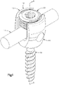
Fig. 1 is an isometric view of a fastener device, according to an aspect of the disclosure; -
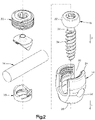
Fig. 2 is an exploded isometric view of the fastener device illustrated inFig. 1 ; -
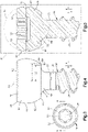
Fig. 3 is a top plan view of a fastener of the fastener device illustrated inFig. 1 ; -
Fig. 4 is a side elevation view of the fastener illustrated inFig. 3 ; -
Fig. 5 is a cross-sectional view of the fastener illustrated inFig. 3 , along line 5-5; -
Fig. 6 is a top plan view of an anchor body of the fastener device illustrated inFig. 1 ; -
Fig. 7 is a cross-sectional view of the anchor body illustrated inFig. 6 , along line 7-7; -
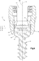
Fig. 8 is a cross-sectional view of the fastener device illustrated inFig. 1 , along line 8-8, the fastener device in a first configuration; -
Fig. 9 is a cross-sectional view of the fastener device illustrated inFig. 1 , along line 8-8, the fastener device in a second configuration; -
Fig. 10 is a cross-sectional view of the fastener device illustrated inFig. 1 , along line 8-8, the fastener device in a third configuration; -
Fig. 11 is a cross-sectional view of the fastener device illustrated inFig. 1 , along line 8-8, the fastener device in the second configuration; -
Fig. 12 is an exploded isometric view of a fastener device according to an aspect of the disclosure, the fastener device including a biasing member and an anchor body; -
Fig. 13 is a top plan view of the biasing member illustrated inFig. 12 ; -
Fig. 14 is a cross-sectional view of the anchor body illustrated inFig. 12 , along line 14-14; -
Fig. 15 is a cross-sectional view of the biasing member and the anchor body illustrated inFig. 12 , along line 14-14, the biasing member and the anchor body in an assembled configuration; -
Fig. 16 is a cross-sectional view of the fastener device illustrated inFig. 12 , along line 14-14, the fastener device in a first configuration; and -
Fig. 17 is a cross-sectional view of the fastener device illustrated inFig. 12 , along line 14-14, the fastener device in a second configuration. - Certain terminology is used in the following description for convenience only and is not limiting. The words "lower" and "upper" designate directions in the drawings to which reference is made. The words "proximally" and "distally" refer to directions toward and away from, respectively, the surgeon using the medical device. The words, "anterior", "posterior", "superior", "inferior" and related words and/or phrases designate preferred positions and orientations in the human body to which reference is made and are not meant to be limiting. The terminology includes the above-listed words, derivatives thereof and words of similar import.
- Aspects of the disclosure will now be described in detail with reference to the drawings, wherein like reference numbers refer to like elements throughout, unless specified otherwise. Certain terminology is used in the following description for convenience only and is not limiting. The term "plurality", as used herein, means more than one. The terms "a portion" and "at least a portion" of a structure include the entirety of the structure. Certain features of the disclosure which are described herein in the context of separate embodiments may also be provided in combination in a single embodiment. Conversely, various features of the disclosure that are described in the context of a single embodiment may also be provided separately or in any subcombination.
- Reference herein to a first structure articulating along or riding along a second structure refers to the first structure directly contacting the second structure, and precludes an intermediate structure or surface between the first structure and the second structure.
- Referring to
Figs. 1 and2 amedical device 10 is configured to secure an elongated member to a portion of a patient's anatomy. As shown in the illustrated embodiment, themedical device 10 can include afastener device 12 configured to secure aspinal rod 14 to a patient's vertebra, for example a pedicle or lateral mass of the patient's vertebra. Thefastener device 12 may be referred to as a pedicle screw when thefastener device 12 is configured to secure thespinal rod 14 to the pedicle of the patient's vertebra. According to one aspect of the disclosure, thefastener device 12 includes ananchor body 16 configured to receive thespinal rod 14, and afastener 18 configured to be inserted into theanchor body 16 and secured to the patient's vertebra. - The
fastener device 12 may further include asaddle 20 and acap 22. As shown in the illustrated embodiment thesaddle 20 is configured to abut both thefastener 18 and thespinal rod 14, and thecap 22 is configured to secure thespinal rod 14 relative to thefastener device 12, as described in further detail below. - According to one aspect of the disclosure, the
anchor body 16 includes anupper end 24, alower end 26 spaced from theupper end 24 in a longitudinal direction L, and ananchor body housing 28 that extends from theupper end 24 to thelower end 26. Theanchor body 16 defines a throughhole 30 that extends through theanchor body housing 28. Thefastener 18 includes ahead 32, a threadedshaft 34 that extends out with respect to thehead 32 in a distal direction D, and aneck 36 that extends between thehead 32 and the threadedshaft 34. Thefastener 18 is configured to be positioned into theanchor body 16 by moving thefastener 18 in the longitudinal direction L, until the threadedshaft 34 passes through thelower end 26 and thehead 32 is positioned within the throughhole 30. - The
fastener device 12 is configured such that when thehead 32 is positioned in the throughhole 30 thefastener 18 is movable, polyaxially, with respect to theanchor body 16. When thehead 32 is positioned in the throughhole 30, thesaddle 20 can be moved in the longitudinal direction L, until thesaddle 20 contacts thehead 32. When thesaddle 20 is contacting thehead 32, thespinal rod 14 can then be moved in the longitudinal direction L until thespinal rod 14 contacts thesaddle 20. When thespinal rod 14 is contacting thesaddle 20, thecap 22 can be moved in the longitudinal direction L until thecap 22 contacts thespinal rod 14. - The
cap 22 can include a single piece, or as shown in the illustrated embodiment, a multiple piece, for example two-pieces. Thecap 22 includes threads 38, for example external threads, that are configured to threadingly engage with threads 40, for example internal threads, of theanchor body 16. Thecap 22 is rotated in a first direction of rotation about an axis, for example an axis parallel to the longitudinal direction L, such that the threads 38 engage with the threads 40 and thecap 22 moves in the longitudinal direction L with respect to theanchor body 16. According to one embodiment, thecap 22 is configured to be rotated until thecap 22 is no longer rotatable in the first direction of rotation when a set torque is applied to thecap 22, thereby securing thespinal rod 14 to thefastener device 12 such that relative movement of thespinal rod 14 and thefastener device 12 is limited, for example prevented, and thereby securing thefastener 18 to theanchor body 16 such that relative movement of thefastener 18 and theanchor body 16 is limited, for example prevented. According to one embodiment, the set torque is between about 2 Newton-meters (N-m) and about 3 N-m. - Referring to
Figs. 3 to 5 , thehead 32 of thefastener 18 includes anouter surface 42. According to one aspect of the disclosure, aportion 44 of theouter surface 42 may be convex, may define a portion of a first sphere S1, or both. The first sphere S1 defines a first diameter D1. According to one aspect of the disclosure, the first diameter D1 may be greater than about 4.5 mm. According to another aspect of the disclosure, the first diameter D1 may be greater than about 5.0 mm. According to another aspect of the disclosure, the first diameter D1 may be in a range between about 5.0 mm and about 8.0 mm. According to another aspect of the disclosure, the first diameter D1 may be about 6.0 mm. - The
outer surface 42 may include one or more additional portions that do not define a portion of the first sphere S1. As shown in the illustrated embodiment, theouter surface 42 may include adistal portion 46 that is positioned in the distal direction D with respect to theportion 44, aproximal portion 48 that is positioned in a proximal direction P, which is opposite the distal direction D, with respect to theportion 44, or both thedistal portion 46 and theproximal portion 48. According to another aspect of the disclosure, an entirety of theouter surface 42 may include theportion 44, such that theouter surface 42 is devoid of thedistal portion 46 and theproximal portion 48. - The
head 32 of thefastener 18 may define alocation 50 such that thefastener 18 is devoid of any locations positioned in the proximal direction P from thelocation 50. As shown in the illustrated embodiment, thehead 32 includes anupper surface 52 that defines adrive mechanism 54, thedrive mechanism 54 configured to receive a driving force that rotates thefastener 18 to secure thefastener 18 to a vertebra. According to one aspect of the disclosure, theupper surface 52 can be substantially flat, such that any point on theupper surface 52 can define thelocation 50. According to another aspect of the disclosure, theupper surface 52 can be not flat, for example curved such that an apex of theupper surface 52 defines thelocation 50. - According to one aspect of the disclosure, the
fastener 18 may include asurface 56 that extends along both thehead 32 and theneck 36. As shown in the illustrated embodiment, thesurface 56 may be concave such that thesurface 56 defines a radius of curvature R. According to one embodiment, the radius of curvature R may be constant along an entirety of thesurface 56. For example, thesurface 56 may define a radius of curvature R of between about 0.25 mm and about 2.0 mm. According to another example, thesurface 56 may define a radius of curvature R of between about 0.4 mm and about 1.0 mm. According to another embodiment, the radius of curvature R may vary along thesurface 56. According to another embodiment, thesurface 56 may include two perpendicular surfaces such that thesurface 56 does not define a radius of curvature R. - The portion of the
fastener 18 between thehead 32 and theshaft 34, for example theneck 36, is a potential area where thefastener 18 may fail under load. According to one aspect of the disclosure, radius of curvature R of theconcave surface 56, may distribute stresses within thefastener 18, thereby increasing the effective strength of thefastener 18. For example, afirst fastener 18 that defines a first radius of curvature R that is larger than a second radius of curvature defined by asecond fastener 18 may result in a better distribution of stresses under load in thefirst fastener 18 when compared to thesecond fastener 18, and thus thefirst fastener 18 may have an increased effective strength compared to thesecond fastener 18. - According to one aspect of the disclosure, the
neck 36 defines a second diameter D2 that may be measured both in a direction perpendicular to the distal direction D and at alocation 57 that is in the distal direction D with respect to thesurface 56. As shown in the illustrated embodiment, the second diameter D2 may be measured both in the distal direction D and at thelocation 57 which is in the distal direction D with respect to an entirety of thesurface 56 which defines the radius of curvature R. The second diameter D2 may be constant such that the second diameter D2 at first and second locations spaced apart with respect to the distal direction D, is the same. Alternatively, the second diameter D2 may vary, for example decrease in the distal direction D2. - According to another aspect of the disclosure, the second diameter D2 may be in a range between about 1.0 mm and about 4.0 mm. According to another aspect of the disclosure, the second diameter D2 may be about 2.5 mm. The
fastener 18 defines a ratio of the first diameter D1 to the second diameter D2. According to one aspect of the disclosure, the ratio of the first diameter D1 to the second diameter D2 is in a range between about 2 to 1 and about 3 to 1. - The
fastener 18 may be elongate along an axis, for example acentral fastener axis 58. As shown in the illustrated embodiment, thecentral fastener axis 58 is parallel to the distal direction D. According to one aspect of the disclosure, theportion 44 of theouter surface 42 may include afirst point 60 that is located in the distal direction with respect to all other points of theportion 44 of theouter surface 42, thesurface 56 includes asecond point 62 that is located in the proximal direction P with respect to all other points of thesurface 56, thefirst point 60 is spaced from the central fastener axis 58 a first distance L1 measured in a direction perpendicular to the distal direction D, thesecond point 62 is spaced from the central fastener axis 58 a second distance L2 measured in a direction perpendicular to the distal direction D, and the first distance L1 is greater than the second distance L2. - The
head 32 may include anintermediate surface 64 that extends between thesurface 56 and theouter surface 42. According to one aspect of the disclosure, at least a portion of theintermediate surface 64 may be substantially flat and perpendicular to the distal direction D. - The
fastener 18 may be configured such that all lines that both lie entirely within a plane PI that is parallel to the distal direction D and that are tangent to theportion 44 of theouter surface 42 are noncollinear with all lines that both lie entirely within the plane PI and that are tangent to thesurface 56. For example, aline 66 which both lies entirely within the plane PI and is tangent to theportion 44 is not collinear with aline 68 which both lies entirely within the plane PI and is tangent to thesurface 56. - Referring to
Figs. 6 and 7 , theanchor body 16 may define a rod-receivingchannel 69 that is configured to receive a spinal rod, for example the spinal rod 14 (as shown inFig. 1 ). The rod-receivingchannel 69 extends through theanchor body housing 28 and may be oriented such that the rod-receivingchannel 69 is offset from, for example perpendicular to, the throughhole 30. As shown in the illustrated embodiment, the rod-receivingchannel 69 may be a U-shaped channel. - The
anchor body 16 may further include aninner surface 70 that defines at least a portion of the throughhole 30. According to one aspect of the disclosure, aportion 72 of theinner surface 70 may be concave, may define a portion of a second sphere S2, or both. The second sphere S2 defines a third diameter D3. According to one aspect of the disclosure, the third diameter D3 is equal to the first diameter D1. According to another aspect of the disclosure, the third diameter D3 is either greater than or less than the first diameter D1. - The
inner surface 70 defines a minimum inner diameter D4 that is measured both in a direction perpendicular to the longitudinal direction L and at alocation 74 that is closer to thelower end 26 as measured along the longitudinal direction L than thelocation 74 is to theupper end 24 as measured along the longitudinal direction L. As shown in the illustrated embodiment, thelocation 74 may be spaced a distance from thelower end 26 measured along the longitudinal direction L, such that theinner surface 70 tapers radially outward with respect to a centralanchor body axis 76 as theinner surface 70 extends from thelocation 74 to thelower end 26. According to another aspect of the disclosure, thelocation 74 may be located at thelower end 26. According to one embodiment, thelocation 74 may be positioned on theportion 72 such that no point on theportion 72 is positioned in the longitudinal direction L with respect to thelocation 74. - The
anchor body 16 defines an inner diameter D5 that is greater than the minimum inner diameter D4. According to one aspect of the disclosure, the inner diameter D5 may be defined by theinner surface 70 at a location that is spaced from theportion 72 in a direction opposite the longitudinal direction L. According to another aspect of the disclosure, the inner diameter D5 may be defined by theupper end 24. According to one aspect of the disclosure, the inner diameter D5 may be a maximum inner diameter of theanchor body 16. - According to one aspect of the disclosure, the
upper end 24 defines an upper opening 78 where the throughhole 30 exits theanchor body housing 28 in the direction opposite the longitudinal direction L, thelower end 26 defines alower opening 80 where the throughhole 30 exits theanchor body housing 28 in the longitudinal direction L, or both. As shown in the illustrated embodiment, theanchor body 16 may define a plane P2 (shown as a line which extends into and out of the page). The plane P2 may include an entirety of thelower opening 80, may be perpendicular to the longitudinal direction L, or both. - Referring to
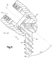
Figs. 8 and9 , thefastener device 12 defines an assembled configuration in which theportion 44 of theouter surface 42 rides along (contacts at more than one point) theportion 72 of theinner surface 70 such that thefastener 18 is movable with respect to theanchor body 16. The contact between theportion 44 and theportion 72 may define a circle, a portion of a circle, a portion of a sphere, or any combination thereof. According to one aspect of the disclosure, thefastener 18 is movable polyaxially with respect to theanchor body 16 such that thefastener device 12 defines a cone of angulation that includes all of the angles at which thecentral fastener axis 58 and the centralanchor body axis 76 can be offset from one another when thefastener device 12 is in the assembled configuration. The cone of angulation may be defined by a maximum angle α (alpha), for example the cone of angulation may be twice the maximum angle α (alpha). - The maximum angle α (alpha) is measured between the
central fastener axis 58 and the centralanchor body axis 76 when theanchor body 16 abuts theneck 36 at a location that is spaced in the distal direction D from an entirety of thesurface 56 such that movement of thefastener 18 relative to theanchor body 16 in at least one direction is blocked. According to one aspect of the disclosure the maximum angle α (alpha) is greater than about 45 degrees. According to another aspect of the disclosure the maximum angle α (alpha) is greater than about 50 degrees. According to another aspect of the disclosure the maximum angle α (alpha) is between about 50 degrees and about 60 degrees. For example, thefastener device 12 may be configured as a cervical fastener device with a maximum angle α (alpha) of about 50 degrees. As another example thefastener device 12 may be configured as a lumbar fastener device with a maximum angle α (alpha) of about 30 degrees. - As shown in
Fig. 8 , when thefastener device 12 is in the configuration thecentral fastener axis 58 and the centralanchor body axis 76 may be parallel, for example collinear. As shown inFig. 9 , when thefastener device 12 is in the configuration thecentral fastener axis 58 and the centralanchor body axis 76 may be angularly offset, for example by the maximum angle α (alpha) or by any angle less than maximum angle α (alpha). - Referring to
Figs. 5 ,7 , and8 , because the first diameter D1 is larger than the minimum inner diameter D4 thehead 32 of thefastener 18 is not able to be inserted into the throughhole 30 along the direction opposite the longitudinal direction L such that theportion 44 of theouter surface 42 rides along theportion 72 of theinner surface 70. Instead, because the inner diameter D5 is greater than the first diameter D1, thefastener 18 is configured to be inserted into the throughhole 30 along the longitudinal direction L such that theportion 44 of theouter surface 42 rides along theportion 72 of theinner surface 70. Thus thefastener device 12 can be described as a top-loading fastener device as opposed to a bottom-loading (or pop-on) fastener device. Thefastener device 12 being configured as a top-loading fastener device allows the size of the first diameter D1 and the size of the second diameter D2 to remain larger than in a comparable bottom-loading screw, which can result in afastener device 12, and specifically afastener 18, with increased strength. - Referring to
Fig. 9 , according to one aspect of the disclosure thefastener device 12 defines a configuration in which thelocation 50 is positioned a third distance L3 from theupper end 24 measured along the longitudinal direction L, thelower end 26 is positioned a fourth distance L4 from theupper end 24 measured along the longitudinal direction L, and the third distance L3 is greater than the fourth distance L4. According to one aspect of the disclosure thefastener device 12 defines a configuration in which thelocation 50 is spaced in the longitudinal direction L with respect to the plane P2. - According to one aspect of the disclosure, the
fastener device 12 defines a configuration (referred to herein as a maximum angled configuration) in which both theportion 44 of theouter surface 42 rides along theportion 72 of theinner surface 70, and theanchor body 16 abuts theneck 36 at thelocation 57 that is spaced in the distal direction D from an entirety of thesurface 56 such that movement of thefastener 18 relative to theanchor body 16 in at least one direction is blocked. - Referring to
Figs. 8 and9 , thefastener device 12 is illustrated with thesaddle 20 abutting thefastener 18, and thespinal rod 14 and thecap 22 are not shown. The description ofFigs. 8 and9 applies to thefastener device 12 with and without any combination of thesaddle 20, thecap 22, and thespinal rod 14. - As shown in the illustrated embodiment, when the
fastener device 12 is in the maximum angled configuration agap 84 is defined between thesurface 56 and theanchor body 16. Thegap 84 is enclosed in both the longitudinal direction L and the direction opposite the longitudinal direction L. According to one aspect of the disclosure, when the fastener device is in the maximum angled configuration, a region of contact that includes all of the points of contact between theanchor body 16 and thefastener 18 as measured in a plane that is perpendicular to the longitudinal direction L defines a portion of a circle that is less than a full circle. - Referring to
Figs. 4 and9 , according to one aspect of the disclosure the strength of thefastener 18 may be increased by maximizing the second diameter D2. However, increasing the size of the second diameter D2 while not changing other dimensions of thefastener 18, for example the first diameter D1, may result in afastener device 12 with a lower maximum angle α (alpha). Accordingly, maximizing the second diameter D2 while maintaining the ratio of the first diameter D1 to the second diameter D2 may result in afastener 18 with increased strength and afastener device 12 with a greater maximum angle α (alpha). According to one aspect of the disclosure the strength of thefastener 18 may be increased by increasing the size of the radius of curvature R. The increased size of the radius of curvature R may result in less material being present in the area between thehead 32 and the threadedshaft 34, however the large radius of curvature may reduce stress concentrations within the area between thehead 32 and the threadedshaft 34, thereby resulting in increased strength of thefastener 18. - Additionally, in the
fastener device 12 as shown in the illustrated embodiment theportion 44 of theouter surface 42 articulates along or rides along theportion 72 of theinner surface 70 such that theportion 44 directly contacts theportion 72. According to the illustrated embodiment, the fastener device may be devoid of a collet or other intermediate structure between theportion 44 and theportion 72. The inclusion of a collet or other intermediate structure positioned within the throughhole 30 of a given size would result in the use of a fastener with a first diameter D1 being smaller than the first diameter D1 of thefastener 18 which is configured for use with thefastener device 12 that is devoid of a collet or other intermediate structure. Thus, thefastener device 12 being devoid of a collet or other intermediate structure between theportion 44 and theportion 72 may result in increased strength in thefastener 18 configured for use with thefastener device 12. - Referring to
Figs. 1 to 9 , a method of making thefastener device 12 may include the step of inserting thefastener 18 into theanchor body 16 such that the threadedshaft 34 passes through thelower opening 80 of theanchor body 16. The method of making thefastener device 12 may further include the steps of: inserting thesaddle 20 into theanchor body 16; inserting thespinal rod 14 into theanchor body 16; inserting thecap 22 into theanchor body 16; or any combination thereof. - The method of making the
fastener device 12 may further include the step of tightening thecap 22. According to one aspect of the disclosure, thefastener device 12 is configured such that after the step of inserting thefastener 18 into theanchor body 16, and before the tightening step thefastener 18 is freely movable within the throughhole 30 with respect to theanchor body 16, and vice versa. Thefastener 18 being freely movable includes thefastener 18 being translatable with respect to theanchor body 16 along the longitudinal direction L, thefastener 18 being polyaxially rotatable with respect to theanchor body 16, or both. - Referring to
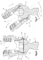
Figs. 10 and11 , thefastener 18 being freely movable within the throughhole 30 with respect to theanchor body 16 may result in undesired movement of theanchor body 16 relative to thefastener 18 during insertion of thefastener 18 intohole 30. As shown in the illustrated embodiment ofFig. 10 , during insertion, thefastener 18 and theanchor body 16 may be offset with respect to the longitudinal direction L, for example thecentral fastener axis 58 and the centralanchor body axis 76 may be angularly offset by an angle, β (beta). The angular offset of thecentral fastener axis 58 and the centralanchor body axis 76 may result in a force, such as the force of gravity on theanchor body 16, being sufficient to move theanchor body 16 relative to thefastener 18, for example until theneck 36 of thefastener 18 contacts theanchor body 16, as shown inFig. 11 . - Referring to
Figs. 12 to 17 , thefastener device 12 may include a biasingmember 102 configured to restrict, for example by providing a force, relative movement of theanchor body 16 and thefastener 18 after thefastener 18 is inserted into theanchor body 16, and before thecap 22 is inserted into the throughhole 30 such that thecap 22 abuts thespinal rod 14. -
Biasing member 102 may be disposed in arecess 106 inanchor body 16 such that movement of the biasingmember 102 relative to theanchor body 16 is limited in a direction, for example a direction parallel to the centralanchor body axis 76. The biasingmember 102 may further be configured to provide a force on theouter surface 42 of thefastener 18. As shown in the illustrated embodiment, the biasingmember 102 may be a split ring. According to another embodiment, the biasingmember 102 may be a non-circular shape, such as but not limited to a polygonal shape. As shown in the illustrated embodiment, therecess 106 may be defined by theanchor body 16. - According to one aspect of the disclosure, the biasing
member 102 may be configured to expand radially with respect to the centralanchor body axis 76. For example, before thefastener 18 is inserted into the throughhole 30, the biasingmember 102 defines an inner diameter D6 having a first dimension. The biasingmember 102 may be configured to expand as thefastener 18 is inserted into the throughhole 30, and theouter surface 42 of the fastener contacts the biasingmember 102. Once thefastener 18 is fully seated within the throughhole 30, such that no further movement of thefastener 18 in the longitudinal direction L relative to theanchor body 18, is possible due to theouter surface 42 abutting theinner surface 70, the inner diameter D6 has a second dimension that is larger than the first dimension. The biasingmember 102 is configured such that increasing the size of the inner diameter D6 imparts a force on theouter surface 44 of thefastener 18. According to one aspect of the disclosure, thefastener device 12 is configured such that the biasingmember 102 imparts the force on theouter surface 42 in a direction substantially perpendicular to the centralanchor body axis 76. - Referring to
Fig. 13 , the biasingmember 102 includes aninner surface 112 and anouter surface 114. As shown in the illustrated embodiment, theinner surface 112 defines a throughhole 115 that extends through the biasingmember 100. Theinner surface 112 may define at least a portion, for example greater than half of, a circle. The circle of which at least a portion is defined by theinner surface 112 may include acenter 116. The inner diameter D6 is measured along a straight line from a first point on theinner surface 112, through thecenter 116, to a second point on theinner surface 112 spaced apart from the first point. - The biasing
member 102 may further define an outer diameter D7 measured along a straight line from a first point on theouter surface 114, through thecenter 116, to a second point on theouter surface 114 spaced apart from the first point on theouter surface 114. The outer diameter D7 is greater than the inner diameter D6. - Referring to
Fig. 14 , theinner surface 70 of theanchor body 16 defines therecess 106. Therecess 106 extends radially into theinner surface 70 of theanchor body 16 and terminates at abase surface 118. Therecess 106 further extends into theinner surface 70 of theanchor body 16 such that therecess 106 defines a recess height RH. The recess height RH is measured along a straight line that is parallel to the centralanchor body axis 76 from a recessupper surface 120 to a recesslower surface 122. Theanchor body 16 defines an inner diameter D8 measured along a straight line that is perpendicular to the centralanchor body axis 76 from a first point on thebase surface 118, through the centralanchor body axis 76, to a second point on thebase surface 118 that is spaced from the first point. - The
anchor body 16 further defines an inner diameter D9 measured along a straight line that is perpendicular to the centralanchor body axis 76 from a first point on theinner surface 70 that is offset from the recess in the direction opposite the longitudinal direction L, through the centralanchor body axis 76, to a second point on theinner surface 70 that is spaced from the first point. Theanchor body 16 further defines an inner diameter D10 measured along a straight line that is perpendicular to the centralanchor body axis 76 from a first point on aportion 86 of theinner surface 70 that is offset from the recess in the longitudinal direction L, through the centralanchor body axis 76, to a second point on theportion 86 of theinner surface 70 that is spaced from the first point. According to one aspect of the disclosure, the inner diameter D8 is larger than both the inner diameter D9 and the inner diameter D10. As shown in the illustrated embodiment, theportion 86 may be curved and define a portion of a sphere having a diameter. - Referring to
Figs. 12 to 15 , the biasingmember 102 includes an unbiased state when thefastener 18 is not abutting theinner surface 112 and theanchor body 16 is not abutting theouter surface 114. The biasingmember 102 further includes a biased state when thefastener 18 is abutting theinner surface 112, theanchor body 16 is abutting theouter surface 114, or both. Thefastener device 12 may be configured such that the biasingmember 102 is configured to be positioned within therecess 106. According to one aspect of the disclosure, the biasingmember 102 is configured to be in the unbiased state when positioned within therecess 106, and therecess 106 is configured to retain the biasingmember 102 within therecess 106, as shown inFig. 15 . - As shown in the illustrated embodiment, the
fastener device 12 may be configured such that, in the unbiased state, the inner diameter D6 is smaller than both the inner diameter D9 and the inner diameter D10, the outer diameter D7 is larger than both the inner diameter D9 and the inner diameter D10, and the inner diameter D8 is larger than the outer diameter D7. The biasingmember 102, in the unbiased state, is disposed within therecess 106 such that movement of the biasingmember 102 out of the recess along the longitudinal direction L is blocked by theupper surface 120 and thelower surface 122. Therecess 106 further provides room for the biasingmember 102 to expand radially out toward thebase surface 118. - The biasing
member 102 may further include atop surface 130 and abottom surface 132 opposite thetop surface 130. As shown in the illustrated embodiment, thebottom surface 132 faces in the longitudinal direction L and thetop surface 130 faces in the direction opposite the longitudinal direction L. The biasingmember 102 may further include one or moretapered surfaces 134. The one or moretapered surfaces 134 may include a first tapered surface 134' that extends between theupper surface 130 and theinner surface 112, a secondtapered surface 134" that extends between thelower surface 132 and theinner surface 112, or both. The one or moretapered surfaces 134 may be linear, curved, or partially linear and partially curved. The one or moretapered surfaces 134 are configured to enable easier entry of thefastener 18 into the throughhole 115, for example by lowering the amount of force required compared to a biasingmember 102 devoid of the one or moretapered surfaces 134. - Referring to
Fig. 16 , thefastener 18 is configured to be inserted into the throughhole 30 such that the threadedshaft 34 extends through thelower opening 80 and theouter surface 42 abuts theinner surface 112, thereby transitioning the biasingmember 102 into a biased state. Thefastener device 12 may define a fully seated configuration in which theouter surface 42 abuts theportion 86 of theinner surface 70. When thefastener device 12 is in the fully seated configuration the biasingmember 102 exerts a force on thefastener 18, and that force resists relative to movement of thefastener 18 and theanchor body 16. - Relative movement of the
fastener 18 and theanchor body 16 along the longitudinal direction L is resisted by the biasingmember 102, which is exerting an inward radial force on thefastener 18, abutting either theupper surface 120 or thelower surface 122. Relative rotation, for example polyaxial rotation, of thefastener 18 and theanchor body 16 is resisted by a drag force or friction force resulting from the inward radial force exerted by the biasingmember 102 on thefastener 18. - According to one aspect of the disclosure, the
fastener 18 defines awidest location 136 that is larger, as measured along a straight line perpendicular to thecentral fastener axis 58 from a first point on theouter surface 42, through thecentral fastener axis 58, to a second point on theouter surface 42, than any other location on thehead 32. Thefastener device 12 may be configured such that in the fully seated configuration, when thecentral fastener axis 58 is parallel to the centralanchor body axis 76, the biasingmember 102 abuts theouter surface 42 at a location aligned with thewidest location 136 with respect to the distal direction D. - According to another embodiment, the
fastener device 12 may be configured such that in the fully seated configuration, when thecentral fastener axis 58 is parallel to the centralanchor body axis 76, the biasingmember 102 abuts theouter surface 42 at a location either spaced from thewidest location 136 in the distal direction D, or spaced from thewidest location 136 in the proximal direction P. - The method of making the
fastener device 12 may include the step of inserting thefastener 18 into the biasingmember 102 until theouter surface 42 abuts theportion 86 of theinner surface 70. The above step of inserting thefastener 18 into the biasingmember 102 may include the step of radially expanding the biasingmember 102 such that the inner diameter D6 increases. The above step of inserting thefastener 18 into the biasingmember 102 may further include, after the step of radially expanding the biasingmember 102, the step of radially contracting the biasingmember 102 such that the inner diameter D6 decreases. - Referring to
Fig. 17 , the biasingmember 102 is configured to resist undesired relative movement of thefastener 18 and theanchor body 16, but allow desired relative movement of thefastener 18 and theanchor body 16. In use, when thefastener 18 is in the fully seated configuration, theanchor body 16 may be moved relative to thefastener 18, for example by a surgeon manipulating at least one of thefastener 18 and theanchor body 16. Additionally, when thefastener 18 is in the fully seated configuration, the biasingmember 102 prevents relative movement of theanchor body 16 relative to thefastener 18, for example due to gravity acting on theanchor body 16 when thecentral fastener axis 58 is angular offset from the centralanchor body axis 76 by the angle β (beta). According to one aspect of the disclosure, the angle β (beta) may be between 0 and the maximum angle α (alpha). - The description of the biasing
member 102 illustrated inFigs. 12 to 17 also applies to the embodiments illustrated inFigs. 1 to 11 . Additionally, the description of the embodiments illustrated inFigs. 1 to 11 is applicable to the embodiments illustrated inFigs. 12 to 17 . - It will be appreciated that the foregoing description provides examples of the disclosed system and technique. However, it is contemplated that other implementations of the disclosure may differ in detail from the foregoing examples. All references to the disclosure or examples thereof are intended to reference the particular example being discussed at that point and are not intended to imply any limitation as to the scope of the disclosure more generally. All language of distinction and disparagement with respect to certain features is intended to indicate a lack of preference for those features, but not to exclude such from the scope of the disclosure entirely unless otherwise indicated.
- Recitation of ranges of values herein are merely intended to serve as a shorthand method of referring individually to each separate value falling within the range including the stated ends of the range, unless otherwise indicated herein, and each separate value is incorporated into the specification as if it were individually recited herein. All methods described herein can be performed in any suitable order unless otherwise indicated herein or otherwise clearly contradicted by context.
- Although the disclosure has been described in detail, it should be understood that various changes, substitutions, and alterations can be made herein without departing from the spirit and scope of the invention as defined by the appended claims. Moreover, the scope of the present disclosure is not intended to be limited to the particular embodiments described in the specification. As one of ordinary skill in the art will readily appreciate from the disclosure of the present invention, processes, machines, manufacture, composition of matter, means, methods, or steps, presently existing or later to be developed that perform substantially the same function or achieve substantially the same result as the corresponding embodiments described herein may be utilized according to the present disclosure.
- The invention also provides fastener devices having features specified in the following numbered clauses.
-
Clause 1. A fastener device configured to secure a spinal rod relative to a bone, the fastener device comprising:- an anchor body including an anchor body housing, the anchor body defining a through hole that extends through the anchor body housing, the anchor body further defining a rod-receiving channel that is configured to receive the spinal rod and that is offset with respect to the through hole, the anchor body further including an upper end, a lower end, and an inner surface, the inner surface defining a least a portion of the through hole; and
- a fastener including a head, a threaded shaft that extends out with respect to the head in a distal direction, and a neck that extends between the head and the threaded shaft, the head including an outer surface configured to articulate along the inner surface when the fastener head is inserted in the through hole, at least a portion of the outer surface being convex and defining a portion of a sphere, the sphere defining a first diameter, and the fastener including a concave surface that extends along both the head and the neck, the neck defining a second diameter measured: 1) in a direction perpendicular to the distal direction, and 2) at a location spaced in the distal direction of an entirety of the concave surface,
- wherein the fastener defines a ratio of the first diameter to the second diameter in a range between about 2 to 1 and about 3 to 1.
- Clause 2. The fastener device of
clause 1, wherein:- the fastener is elongate along a central axis that is parallel to the distal direction;
- the portion of the outer surface includes a first point that is located in the distal direction with respect to all other points of the portion of the outer surface;
- the concave surface includes a second point that is located in a proximal direction, which is opposite the distal direction, with respect to all other points of the concave surface; and
- the first point is spaced from the central axis a first distance measured in a direction perpendicular to the distal direction, the second point is spaced from the central axis a second distance measured in a direction perpendicular to the distal direction, and the first distance is greater than the second distance.
- Clause 3. The fastener device of
clause 1, wherein the location is a first location, the through hole extends away from the upper end and toward the lower end in a longitudinal direction, and the inner surface defines a minimum inner diameter that is both: 1) measured at a second location that is on the inner surface, and 2) measured in a direction perpendicular to the longitudinal direction, the second location is closer to the lower end as measured along the longitudinal direction, than the second location is to the upper end as measured along the longitudinal direction. - Clause 4. The fastener device of clause 3, wherein the lower end defines a lower opening where the through hole exits the anchor body housing, the anchor body defines a plane that includes an entirety of the lower opening, the head of the fastener defines a third location such that the fastener is devoid of any locations positioned in a proximal direction, which is opposite the distal direction, from the third location, and the fastener device defines a configuration in which the third location is positioned a first distance from the upper end, the lower end is positioned a second distance from the upper end, the first distance and the second distance each measured along the longitudinal direction, and the first distance is greater than the second distance.
-
Clause 5. The fastener device of clause 3, wherein the first diameter is larger than the minimum inner diameter. - Clause 6. The fastener device of
clause 5, wherein the upper end defines an upper opening where the through hole exits the anchor body housing, the upper opening defines an inner diameter measured in the direction perpendicular to the longitudinal direction, and the inner diameter is greater than both the first diameter and the minimum inner diameter. -
Clause 7. The fastener device ofclause 1, wherein all lines that: 1) lie entirely within a plane parallel to the distal direction, and 2) are tangent to the portion of the outer surface are noncollinear with all lines that: 1) lie entirely within the plane, and 2) are tangent to the concave surface. -
Clause 8. The fastener device ofclause 1, further comprising a stabilization mechanism configured to be positioned in the through hole such that when the fastener is inserted in the through hole such that the outer surface contacts the inner surface the stabilization mechanism exerts a force on the fastener that resists relative movement of the fastener and the anchor body. - Clause 9. The fastener device of
clause 8, wherein the stabilization mechanism includes a biasing member configured to expand as the head of the fastener contacts the biasing member, such that the expanded biasing member exerts the force on the outer surface of the fastener. -
Clause 10. The fastener device of clause 9, wherein the anchor body defines a recess configured to receive the biasing member such that the biasing member is captured within the recess. - Clause 11. A fastener device configured to secure a spinal rod relative to a bone, the fastener device comprising:
- an anchor body including an anchor body housing, the anchor body defining a through hole that extends through the anchor body housing, the anchor body further defining a rod-receiving channel that is configured to receive the spinal rod and that is offset with respect to the through hole, the anchor body further including an upper end, a lower end, and an inner surface that defines a least a portion of the through hole, at least a portion of the inner surface defining a portion of a first sphere; and
- a fastener including a head, a threaded shaft that extends out with respect to the head in a distal direction, and a neck that extends between the head and the threaded shaft, the head including an outer surface, at least a portion of the outer surface defining a portion of a second sphere, and the head further including a concave surface of the fastener that extends along both the head and the neck
- wherein the fastener device defines a configuration in which both: 1) the portion of the outer surface rides along the portion of the inner surface, and 2) the anchor body abuts the neck at a location that is spaced in the distal direction from an entirety of the concave surface such that movement of the fastener relative to the anchor body in at least one direction is blocked.
-
Clause 12. The fastener device of clause 11, wherein:- the fastener is elongate along a central axis that is parallel to the distal direction;
- the portion of the outer surface includes a first point that is located in the distal direction with respect to all other points of the portion of the outer surface;
- the concave surface includes a second point that is located in a proximal direction, which is opposite the distal direction, with respect to all other points of the concave surface; and
- the first point is spaced from the central axis a first distance measured in a direction perpendicular to the distal direction, the second point is spaced from the central axis a second distance measured in a direction perpendicular to the distal direction, and the first distance is greater than the second distance.
- Clause 13. The fastener device of clause 11, wherein the fastener is elongate along a central fastener axis that is parallel to the distal direction, the second sphere defines a first diameter, the neck defines a second diameter that is measured in a plane that is both normal to the central fastener axis and intersects the location, and the fastener defines a ratio of the first diameter to the second diameter in a range between about 2 to 1 and about 3 to 1.
-
Clause 14. The fastener device of clause 11, wherein the through hole extends away from the upper end and toward the lower end in a longitudinal direction, and the portion of the inner surface is closer to the lower end as measured along the longitudinal direction, than the portion of the inner surface is to the upper end as measured along the longitudinal direction. - Clause 15. The fastener device of
clause 14, wherein the lower end defines a lower opening where the through hole exits the anchor body housing, the location is a first location, the anchor body defines a plane that includes an entirety of the lower opening, the head of the fastener defines a second location such that the fastener is devoid of any locations positioned in a proximal direction, which is opposite the distal direction, from the second location, and when the fastener device is in the configuration the second location is positioned a first distance from the upper end, the lower end is positioned a second distance from the upper end, the first distance and the second distance each measured along the longitudinal direction, and the first distance is greater than the second distance. -
Clause 16. The fastener device ofclause 14, wherein the second sphere defines a first diameter, the location is a first location, the inner surface defines a minimum inner diameter that is both: 1) measured at a second location that is on the inner surface, and 2) measured in a direction perpendicular to the longitudinal direction, and the first diameter is larger than the minimum inner diameter. - Clause 17. The fastener device of
clause 16, wherein the upper end defines an upper opening where the through hole exits the anchor body housing, the upper opening defines an inner diameter measured in the direction perpendicular to the longitudinal direction, and the inner diameter is greater than both the first diameter and the second diameter. -
Clause 18. The fastener device of clause 11, wherein the fastener is elongate along a central fastener axis that is parallel to the distal direction, the through hole extends away from the upper end and toward the lower end in a longitudinal direction along a central hole axis, and when the fastener device is in the configuration the central fastener axis is angularly offset from the central hole axis by an angle that is greater than 45 degrees. - Clause 19. The fastener device of clause 11, wherein all lines that: 1) lie entirely within a plane parallel to the distal direction, and 2) are tangent to the portion of the outer surface are noncollinear with all lines that: 1) lie entirely within the plane, and 2) are tangent to the concave surface.
-
Clause 20. The fastener device of clause 11, further comprising a stabilization mechanism configured to be positioned in the through hole such that when the fastener is inserted in the through hole such that the outer surface contacts the inner surface the stabilization mechanism exerts a force on the fastener that resists relative movement of the fastener and the anchor body. - Clause 21. The fastener device of
clause 20, wherein the stabilization mechanism includes a biasing member configured to expand as the head of the fastener contacts the biasing member, such that the expanded biasing member exerts the force on the outer surface of the fastener. -
Clause 22. The fastener device of clause 21, wherein the anchor body defines a recess configured to receive the biasing member such that the biasing member is captured within the recess. - Clause 23. A fastener device configured to secure a spinal rod relative to a bone, the fastener device comprising:
- an anchor body including an anchor body housing, the anchor body defining a through hole that extends through the anchor body housing, the anchor body further defining a rod-receiving channel that is configured to receive the spinal rod and that is offset with respect to the through hole, the anchor body further including an upper end, a lower end, and an inner surface, the inner surface defining at least a portion of the through hole; and
- a fastener including a head, a threaded shaft that extends out with respect to the head in a distal direction, and a neck that extends between the head and the threaded shaft, the head including a convex outer surface, a portion of the convex outer surface both defining a portion of a sphere and being configured to articulate along the inner surface when the fastener head is positioned in the through hole, the fastener including a concave surface that extends along both the head and the neck,
- wherein the fastener is configured such that all lines that: 1) lie entirely within a plane parallel to the distal direction, and 2) are tangent to the portion of the convex outer surface are noncollinear with all lines that: 1) lie entirely within the plane, and 2) are tangent to the concave surface.
-
Clause 24. The fastener device of clause 23, wherein the through hole extends away from the upper end and toward the lower end in a longitudinal direction, and the inner surface defines a minimum inner diameter at an anchor location on the inner surface, such that the anchor location is closer to the lower end as measured along the longitudinal direction, than the anchor location is to the upper end as measured along the longitudinal direction. - Clause 25. The fastener device of clause 23, wherein the lower end defines a lower opening where the through hole exits the anchor body housing, the anchor body defines a plane that includes an entirety of the lower opening, the head of the fastener defines a fastener location such that the fastener is devoid of any locations positioned in a proximal direction, which is opposite the distal direction, from the fastener location, and the fastener device defines a configuration in which the fastener location is positioned a first distance from the upper end, the lower end is positioned a second distance from the upper end, the first distance and the second distance are each measured along the longitudinal direction, and the first distance is greater than the second distance.
-
Clause 26. The fastener device of clause 23, wherein the sphere defines a first diameter, the through hole extends along a central anchor body axis, the inner surface defines a minimum inner diameter that is both: 1) measured at a location that is on the inner surface, and 2) measured in a direction perpendicular to the central anchor body axis, and the first diameter is larger than the minimum inner diameter. - Clause 27. The fastener device of clause 23, further comprising a stabilization mechanism configured to be positioned in the through hole such that when the fastener is inserted in the through hole such that the outer surface contacts the inner surface the stabilization mechanism exerts a force on the fastener that resists relative movement of the fastener and the anchor body.
-
Clause 28. The fastener device of clause 27, wherein the stabilization mechanism includes a biasing member configured to expand as the head of the fastener contacts the biasing member, such that the expanded biasing member exerts the force on the outer surface of the fastener. - Clause 29. The fastener device of
clause 28, wherein the anchor body defines a recess configured to receive the biasing member such that the biasing member is captured within the recess. -
Clause 30. A fastener device configured to secure a spinal rod relative to a bone, the fastener device comprising:- an anchor body including an anchor body housing and a central axis, the anchor body defining a through hole that extends through the anchor body housing along the central axis, the anchor body further defining a rod-receiving channel that is configured to receive the spinal rod and that is offset with respect to the through hole, the anchor body further including an upper end, a lower end spaced from the upper end in a first direction, and an inner surface, defining at least a portion of the through hole, the inner surface including: 1) a first portion that is curved and defines a portion of a sphere having a first diameter, 2) a second portion that is cylindrical and that defines a second diameter that is equal to or greater than the first diameter, and 3) a third portion that defines a third diameter that is greater than both the first diameter and the second diameter, wherein the first portion is closer to the lower end with respect to the first direction than the third portion is from the lower end with respect to the first direction, and the third portion is closer to the lower end with respect to the first direction than the second portion is from the lower end with respect to the first direction; and
- a fastener including a head and a threaded shaft that extends out with respect to the head, the head including an outer surface configured to articulate along the first portion of the inner surface when the fastener head is inserted in the through hole.
- Clause 31. The fastener device of
clause 30, further comprising a biasing member configured to be inserted into the through hole and positioned such that the biasing member is aligned with the third portion along a second direction that is perpendicular to the first direction. -
Clause 32. The fastener device of clause 31, wherein the biasing member is a split ring that includes an inner surface that faces the central axis when the split ring is inserted in the through hole, the split ring defines a fourth diameter measured from a first point on the inner surface, through the central axis, to a second point on the inner surface in the second direction, and when the split ring is in an unbiased state the fourth diameter is less than each of the first diameter, the second diameter, and the third diameter. - Clause 33. The fastener device of
clause 32, wherein the split ring includes an outer surface that faces away from the central axis when the split ring is inserted in the through hole, the split ring defines a fifth diameter measured from a first point on the outer surface, through the central axis, to a second point on the outer surface in the second direction, and when the split ring is in an unbiased state the fifth diameter is: 1) greater than the first diameter, 2) greater than the second diameter, 3) and less than the third diameter. -
Clause 34. The fastener device ofclause 30, wherein the sphere is a first sphere, the threaded shaft extends out with respect to the head in a distal direction, the fastener includes a neck that extends between the head and the threaded shaft, at least a portion of the outer surface is convex and defines a portion of a second sphere, the second sphere defining a first fastener diameter, the fastener includes a concave surface that extends along both the head and the neck, the neck defines a second fastener diameter measured: 1) in a direction perpendicular to the distal direction, and 2) at a location spaced in the distal direction of an entirety of the concave surface, and the fastener defines a ratio of the first fastener diameter to the second fastener diameter in a range between about 2 to 1 and about 3 to 1. - Clause 35. The fastener device of
clause 34, wherein:- the fastener is elongate along a central axis that is parallel to the distal direction;
- the portion of the outer surface includes a first point that is located in the distal direction with respect to all other points of the portion of the outer surface;
- the concave surface includes a second point that is located in a proximal direction, which is opposite the distal direction, with respect to all other points of the concave surface; and
- the first point is spaced from the central axis a first distance measured in a direction perpendicular to the distal direction, the second point is spaced from the central axis a second distance measured in a direction perpendicular to the distal direction, and the first distance is greater than the second distance.
-
Clause 36. The fastener device of clause 35, wherein the location is a first location, the through hole extends away from the upper end and toward the lower end in a longitudinal direction, and the inner surface defines a minimum inner diameter that is both: 1) measured at a second location that is on the inner surface, and 2) measured in a direction perpendicular to the longitudinal direction, the second location is closer to the lower end as measured along the longitudinal direction, than the second location is to the upper end as measured along the longitudinal direction.
Claims (15)
- A fastener device (12) configured to secure a spinal rod relative to a bone, the fastener device comprising:an anchor body (16) including an anchor body housing (28), the anchor body defining a through hole that extends through the anchor body housing, the anchor body further defining a rod-receiving channel that is configured to receive the spinal rod and that is offset with respect to the through hole, the anchor body further including an upper end (24), a lower end (26), and an inner surface (70), the inner surface defining a least a portion of the through hole; anda fastener (18) including a head (32), a threaded shaft (34) that extends out with respect to the head in a distal direction (D), and a neck (36) that extends between the head and the threaded shaft, the head including an outer surface (42) configured to articulate along the inner surface when the fastener head is inserted in the through hole, at least a portion (44) of the outer surface being convex and defining a portion of a sphere, the sphere defining a first diameter (Di), and the fastener including a concave surface (56) that extends along both the head and the neck, the neck defining a second diameter (D2) measured: 1) in a direction perpendicular to the distal direction, and 2) at a location (57) spaced in the distal direction of an entirety of the concave surface,wherein the fastener defines a ratio of the first diameter to the second diameter in a range between about 2 to 1 and about 3 to 1.
- The fastener device of claim 1, wherein:the fastener is elongate along a central axis that is parallel to the distal direction;the portion of the outer surface includes a first point that is located in the distal direction with respect to all other points of the portion of the outer surface;the concave surface includes a second point that is located in a proximal direction, which is opposite the distal direction, with respect to all other points of the concave surface; andthe first point is spaced from the central axis a first distance measured in a direction perpendicular to the distal direction, the second point is spaced from the central axis a second distance measured in a direction perpendicular to the distal direction, and the first distance is greater than the second distance.
- The fastener device of claim 1, wherein the location is a first location, the through hole extends away from the upper end and toward the lower end in a longitudinal direction, and the inner surface defines a minimum inner diameter that is both: 1) measured at a second location that is on the inner surface, and 2) measured in a direction perpendicular to the longitudinal direction, the second location is closer to the lower end as measured along the longitudinal direction, than the second location is to the upper end as measured along the longitudinal direction.
- The fastener device of claim 3, wherein the lower end defines a lower opening where the through hole exits the anchor body housing, the anchor body defines a plane that includes an entirety of the lower opening, the head of the fastener defines a third location such that the fastener is devoid of any locations positioned in a proximal direction, which is opposite the distal direction, from the third location, and the fastener device defines a configuration in which the third location is positioned a first distance from the upper end, the lower end is positioned a second distance from the upper end, the first distance and the second distance each measured along the longitudinal direction, and the first distance is greater than the second distance.
- The fastener device of claim 3, wherein the first diameter is larger than the minimum inner diameter.
- The fastener device of claim 5, wherein the upper end defines an upper opening where the through hole exits the anchor body housing, the upper opening defines an inner diameter measured in the direction perpendicular to the longitudinal direction, and the inner diameter is greater than both the first diameter and the minimum inner diameter.
- The fastener device of claim 1, wherein all lines that: 1) lie entirely within a plane parallel to the distal direction, and 2) are tangent to the portion of the outer surface are noncollinear with all lines that: 1) lie entirely within the plane, and 2) are tangent to the concave surface.
- The fastener device of claim 1, further comprising a stabilization mechanism configured to be positioned in the through hole such that when the fastener is inserted in the through hole such that the outer surface contacts the inner surface the stabilization mechanism exerts a force on the fastener that resists relative movement of the fastener and the anchor body.
- The fastener device of claim 8, wherein the stabilization mechanism includes a biasing member configured to expand as the head of the fastener contacts the biasing member, such that the expanded biasing member exerts the force on the outer surface of the fastener.
- The fastener device of claim 9, wherein the anchor body defines a recess configured to receive the biasing member such that the biasing member is captured within the recess.
- The fastener device of claim 1, wherein the fastener is elongate along a central fastener axis that is parallel to the distal direction, the through hole extends away from the upper end and toward the lower end in a longitudinal direction along a central hole axis,wherein the fastener device defines a configuration in which both: 1) the portion of the outer surface rides along a portion of the inner surface, and 2) the anchor body abuts the neck at a location that is spaced in the distal direction from an entirety of the concave surface such that movement of the fastener relative to the anchor body in at least one direction is blocked, andwherein when the fastener device is in the configuration the central fastener axis is angularly offset from the central hole axis by an angle that is greater than 45 degrees.
- The fastener device of claim 11, wherein when the fastener device is in the configuration the central fastener axis is angularly offset from the central hole axis by an angle that is greater than about 50 degrees.
- The fastener device of claim 12, wherein when the fastener device is in the configuration the central fastener axis is angularly offset from the central hole axis by an angle that is between about 50 degrees and about 60 degrees.
- The fastener device of claim 1, wherein the concave surface defines a radius of curvature (R) that is constant along an entirely of the concave surface, wherein the radius of curvature (R) is between about 0.25 mm and about 2.0 mm.
- The fastener device of claim 14, wherein the concave surface defines a radius of curvature (R) that is between about 0.4 mm and about 1.0 mm.
Applications Claiming Priority (3)
| Application Number | Priority Date | Filing Date | Title |
|---|---|---|---|
| US201662300456P | 2016-02-26 | 2016-02-26 | |
| EP17709305.1A EP3419537B1 (en) | 2016-02-26 | 2017-02-24 | Polyaxial bone fixation element |
| PCT/US2017/019280 WO2017147372A1 (en) | 2016-02-26 | 2017-02-24 | Polyaxial bone fixation element |
Related Parent Applications (1)
| Application Number | Title | Priority Date | Filing Date |
|---|---|---|---|
| EP17709305.1A Division EP3419537B1 (en) | 2016-02-26 | 2017-02-24 | Polyaxial bone fixation element |
Publications (2)
| Publication Number | Publication Date |
|---|---|
| EP3973898A1 true EP3973898A1 (en) | 2022-03-30 |
| EP3973898B1 EP3973898B1 (en) | 2025-06-04 |
Family
ID=58231778
Family Applications (2)
| Application Number | Title | Priority Date | Filing Date |
|---|---|---|---|
| EP17709305.1A Active EP3419537B1 (en) | 2016-02-26 | 2017-02-24 | Polyaxial bone fixation element |
| EP21189838.2A Active EP3973898B1 (en) | 2016-02-26 | 2017-02-24 | Polyaxial bone fixation element |
Family Applications Before (1)
| Application Number | Title | Priority Date | Filing Date |
|---|---|---|---|
| EP17709305.1A Active EP3419537B1 (en) | 2016-02-26 | 2017-02-24 | Polyaxial bone fixation element |
Country Status (6)
| Country | Link |
|---|---|
| US (4) | US10675061B2 (en) |
| EP (2) | EP3419537B1 (en) |
| JP (1) | JP6965257B2 (en) |
| CN (1) | CN108697445B (en) |
| AU (1) | AU2017222593B9 (en) |
| WO (1) | WO2017147372A1 (en) |
Families Citing this family (7)
| Publication number | Priority date | Publication date | Assignee | Title |
|---|---|---|---|---|
| WO2012128825A1 (en) * | 2011-03-24 | 2012-09-27 | Jackson Roger P | Polyaxial bone anchor with compound articulation and pop-on shank |
| EP3419537B1 (en) | 2016-02-26 | 2021-09-01 | Medos International Sarl | Polyaxial bone fixation element |
| US10274125B2 (en) * | 2016-04-29 | 2019-04-30 | Really Right Stuff, Llc | Quick detach connector |
| EP3656320B1 (en) * | 2018-11-20 | 2022-08-24 | Biedermann Technologies GmbH & Co. KG | Anchoring member for a polyaxial bone anchoring device and polyaxial bone anchoring device with such an anchoring member |
| EP3831322B1 (en) * | 2019-12-06 | 2025-03-19 | Biedermann Technologies GmbH & Co. KG | Coupling device for coupling a rod to a bone anchor |
| TWI911474B (en) * | 2022-08-09 | 2026-01-11 | 陳健煜 | Two-piece suspension pedicle anchor, and its system and component-set |
| USD1037845S1 (en) * | 2022-11-08 | 2024-08-06 | Madhu Sudan Saini | Screw |
Citations (6)
| Publication number | Priority date | Publication date | Assignee | Title |
|---|---|---|---|---|
| US20040267264A1 (en) * | 2003-06-27 | 2004-12-30 | Konieczynski David D. | Polyaxial bone screw |
| US20060235385A1 (en) * | 2005-03-31 | 2006-10-19 | Dale Whipple | Low profile polyaxial screw |
| WO2009055407A1 (en) * | 2007-10-23 | 2009-04-30 | K2M, Inc. | Posterior pedicle screw having a taper lock |
| WO2011004222A1 (en) * | 2009-07-10 | 2011-01-13 | Kamil Bal | Pedicular screw system |
| WO2012088890A1 (en) * | 2010-12-31 | 2012-07-05 | 上海微创骨科医疗科技有限公司 | Dynamic pedicel screw implant for vertebral arch |
| EP2740424A1 (en) * | 2012-12-10 | 2014-06-11 | Biedermann Technologies GmbH & Co. KG | Anchoring member suitable for use in a polyaxial bone anchoring device and polyaxial bone anchoring device with an enlarged pivot angle to one side |
Family Cites Families (95)
| Publication number | Priority date | Publication date | Assignee | Title |
|---|---|---|---|---|
| DE3614101C1 (en) | 1986-04-25 | 1987-10-22 | Juergen Prof Dr Med Harms | Pedicle screw |
| DE4243951C2 (en) | 1992-12-23 | 1997-07-03 | Plus Endoprothetik Ag | Device for stiffening a spinal column section consisting of at least two vertebrae |
| DE4307576C1 (en) | 1993-03-10 | 1994-04-21 | Biedermann Motech Gmbh | Bone screw esp. for spinal column correction - has U=shaped holder section for receiving straight or bent rod |
| JPH07180714A (en) * | 1993-12-24 | 1995-07-18 | Nippon Steel Corp | Manufacturing method of bolts with excellent fatigue strength |
| US5961517A (en) | 1994-07-18 | 1999-10-05 | Biedermann; Lutz | Anchoring member and adjustment tool therefor |
| DE19509332C1 (en) | 1995-03-15 | 1996-08-14 | Harms Juergen | Anchoring element |
| US5733285A (en) | 1995-07-13 | 1998-03-31 | Fastenetix, Llc | Polyaxial locking mechanism |
| US5879350A (en) | 1996-09-24 | 1999-03-09 | Sdgi Holdings, Inc. | Multi-axial bone screw assembly |
| US5885286A (en) | 1996-09-24 | 1999-03-23 | Sdgi Holdings, Inc. | Multi-axial bone screw assembly |
| US5728098A (en) | 1996-11-07 | 1998-03-17 | Sdgi Holdings, Inc. | Multi-angle bone screw assembly using shape-memory technology |
| WO1998025534A1 (en) | 1996-12-12 | 1998-06-18 | Synthes Ag Chur | Device for connecting a longitudinal support to a pedicle screw |
| US6485494B1 (en) | 1996-12-20 | 2002-11-26 | Thomas T. Haider | Pedicle screw system for osteosynthesis |
| AU725487B2 (en) | 1997-01-22 | 2000-10-12 | Synthes Gmbh | Device for connecting a longitudinal bar to a pedicle screw |
| US5733286A (en) | 1997-02-12 | 1998-03-31 | Third Millennium Engineering, Llc | Rod securing polyaxial locking screw and coupling element assembly |
| US6248105B1 (en) | 1997-05-17 | 2001-06-19 | Synthes (U.S.A.) | Device for connecting a longitudinal support with a pedicle screw |
| US5891145A (en) | 1997-07-14 | 1999-04-06 | Sdgi Holdings, Inc. | Multi-axial screw |
| US6010503A (en) | 1998-04-03 | 2000-01-04 | Spinal Innovations, Llc | Locking mechanism |
| FR2778089B1 (en) | 1998-04-30 | 2000-07-21 | Dimso Sa | SPINAL OSTEOSYNTHESIS SYSTEM WITH FLANGE AND LATCH |
| US6113601A (en) | 1998-06-12 | 2000-09-05 | Bones Consulting, Llc | Polyaxial pedicle screw having a loosely coupled locking cap |
| US6090111A (en) | 1998-06-17 | 2000-07-18 | Surgical Dynamics, Inc. | Device for securing spinal rods |
| DK1117336T3 (en) | 1998-09-29 | 2004-07-26 | Synthes Ag | Device for connecting a longitudinal carrier with a bone fixation means |
| US6254602B1 (en) | 1999-05-28 | 2001-07-03 | Sdgi Holdings, Inc. | Advanced coupling device using shape-memory technology |
| FR2794637B1 (en) | 1999-06-14 | 2001-12-28 | Scient X | IMPLANT FOR OSTEOSYNTHESIS DEVICE, ESPECIALLY OF THE RACHIS |
| FR2796545B1 (en) | 1999-07-22 | 2002-03-15 | Dimso Sa | POLY-AXIAL LINK FOR OSTEOSYNTHESIS SYSTEM, ESPECIALLY FOR THE RACHIS |
| DE19936286C2 (en) | 1999-08-02 | 2002-01-17 | Lutz Biedermann | bone screw |
| ES2153331B1 (en) | 1999-08-05 | 2001-09-01 | Traiber S A | INTERVERTEBRAL FIXING SYSTEM FOR COLUMN TREATMENTS. |
| US6280442B1 (en) | 1999-09-01 | 2001-08-28 | Sdgi Holdings, Inc. | Multi-axial bone screw assembly |
| CA2423973A1 (en) | 1999-09-27 | 2001-04-05 | Blackstone Medical, Inc. | A surgical screw system and related methods |
| US6554834B1 (en) * | 1999-10-07 | 2003-04-29 | Stryker Spine | Slotted head pedicle screw assembly |
| DE10005385A1 (en) | 2000-02-07 | 2001-08-09 | Ulrich Gmbh & Co Kg | Pedicle screw |
| DE10005386A1 (en) | 2000-02-07 | 2001-08-09 | Ulrich Gmbh & Co Kg | Pedicle screw for spinal implants takes round bar whose longitudinally rotating shoe notchably accepts notch-legged clip for bar. |
| US6485491B1 (en) | 2000-09-15 | 2002-11-26 | Sdgi Holdings, Inc. | Posterior fixation system |
| US6488681B2 (en) * | 2001-01-05 | 2002-12-03 | Stryker Spine S.A. | Pedicle screw assembly |
| US6869433B2 (en) | 2001-01-12 | 2005-03-22 | Depuy Acromed, Inc. | Polyaxial screw with improved locking |
| DE10115014A1 (en) | 2001-03-27 | 2002-10-24 | Biedermann Motech Gmbh | anchoring element |
| US6974460B2 (en) * | 2001-09-14 | 2005-12-13 | Stryker Spine | Biased angulation bone fixation assembly |
| US6800079B2 (en) * | 2002-03-15 | 2004-10-05 | Lock-N-Stitch, Inc. | Orthopedic stabilization device and method |
| KR100379194B1 (en) | 2001-10-31 | 2003-04-08 | U & I Co Ltd | Apparatus for fixing bone |
| US7066937B2 (en) | 2002-02-13 | 2006-06-27 | Endius Incorporated | Apparatus for connecting a longitudinal member to a bone portion |
| US6837889B2 (en) | 2002-03-01 | 2005-01-04 | Endius Incorporated | Apparatus for connecting a longitudinal member to a bone portion |
| US7879075B2 (en) | 2002-02-13 | 2011-02-01 | Zimmer Spine, Inc. | Methods for connecting a longitudinal member to a bone portion |
| EP3222231A1 (en) * | 2002-10-30 | 2017-09-27 | Zimmer Spine, Inc. | Spinal stabilization system insertion |
| CA2536336C (en) | 2003-08-20 | 2012-04-10 | Sdgi Holdings, Inc. | Multi-axial orthopedic device and system, e.g. for spinal surgery |
| US20060058788A1 (en) | 2004-08-27 | 2006-03-16 | Hammer Michael A | Multi-axial connection system |
| US8951290B2 (en) | 2004-08-27 | 2015-02-10 | Blackstone Medical, Inc. | Multi-axial connection system |
| US20140121703A1 (en) | 2012-10-31 | 2014-05-01 | Roger P. Jackson | Polyaxial bone anchor with pop-on multi-thread shank, some with diametric interference fit inserts |
| US8444681B2 (en) | 2009-06-15 | 2013-05-21 | Roger P. Jackson | Polyaxial bone anchor with pop-on shank, friction fit retainer and winged insert |
| US9168069B2 (en) | 2009-06-15 | 2015-10-27 | Roger P. Jackson | Polyaxial bone anchor with pop-on shank and winged insert with lower skirt for engaging a friction fit retainer |
| CA2601948A1 (en) | 2005-03-25 | 2006-10-05 | Blackstone Medical, Inc. | Multi-axial connection system |
| US20070191839A1 (en) * | 2006-01-27 | 2007-08-16 | Sdgi Holdings, Inc. | Non-locking multi-axial joints in a vertebral implant and methods of use |
| US7699876B2 (en) | 2006-11-08 | 2010-04-20 | Ebi, Llc | Multi-axial bone fixation apparatus |
| US8197517B1 (en) | 2007-05-08 | 2012-06-12 | Theken Spine, Llc | Frictional polyaxial screw assembly |
| US7942910B2 (en) | 2007-05-16 | 2011-05-17 | Ortho Innovations, Llc | Polyaxial bone screw |
| US7951173B2 (en) | 2007-05-16 | 2011-05-31 | Ortho Innovations, Llc | Pedicle screw implant system |
| US8398683B2 (en) | 2007-10-23 | 2013-03-19 | Pioneer Surgical Technology, Inc. | Rod coupling assembly and methods for bone fixation |
| WO2009055747A1 (en) | 2007-10-24 | 2009-04-30 | Nuvasive, Inc. | Surgical fixation system and related methods |
| US8167914B1 (en) | 2008-07-16 | 2012-05-01 | Zimmer Spine, Inc. | Locking insert for spine stabilization and method of use |
| US8377101B2 (en) * | 2008-11-05 | 2013-02-19 | K2M, Inc. | Multi-planar taper lock screw with increased rod friction |
| EP2204129B1 (en) | 2008-12-30 | 2011-11-30 | Biedermann Motech GmbH | Receiving part for receiving a rod for coupling the rod to a bone anchoring element and a bone anchoring device with such a receiving part |
| EP2221013B1 (en) | 2009-02-20 | 2015-08-05 | Biedermann Technologies GmbH & Co. KG | Receiving part for receiving a rod for coupling the rod to a bone anchoring element and a bone anchoring device with such a receiving part |
| US8998959B2 (en) | 2009-06-15 | 2015-04-07 | Roger P Jackson | Polyaxial bone anchors with pop-on shank, fully constrained friction fit retainer and lock and release insert |
| US20130103098A1 (en) * | 2009-06-15 | 2013-04-25 | Roger P. Jackson | Polyaxial bone anchor with pop-on shank, friction fit retainer and lateral alignment feature |
| EP2548525B1 (en) | 2009-09-25 | 2014-04-02 | Biedermann Technologies GmbH & Co. KG | Bone anchoring device |
| AU2010303934B2 (en) | 2009-10-05 | 2014-03-27 | Roger P. Jackson | Polyaxial bone anchor with non-pivotable retainer and pop-on shank, some with friction fit |
| WO2012048338A2 (en) | 2010-10-08 | 2012-04-12 | Alphatec Spine, Inc. | Apparatus and method for locking polyaxial screw heads |
| US9232969B2 (en) | 2010-10-29 | 2016-01-12 | Warsaw Orthopedic, Inc. | Directional control for a multi-axial screw assembly |
| ES2567724T3 (en) | 2010-11-22 | 2016-04-26 | Biedermann Technologies Gmbh & Co. Kg | Polyaxial bone anchoring device |
| ES2481673T3 (en) | 2010-11-24 | 2014-07-31 | Biedermann Technologies Gmbh & Co. Kg | Polyaxial bone anchoring device with extended turning angle |
| ES2461843T3 (en) | 2010-12-23 | 2014-05-21 | Biedermann Technologies Gmbh & Co. Kg | Bone anchoring device |
| EP2659845A1 (en) | 2010-12-27 | 2013-11-06 | Biedermann Technologies GmbH & Co. KG | Polyaxial bone anchoring device |
| US8337530B2 (en) | 2011-03-09 | 2012-12-25 | Zimmer Spine, Inc. | Polyaxial pedicle screw with increased angulation |
| US9060812B2 (en) | 2011-03-29 | 2015-06-23 | Alphatec Spine, Inc. | Screw assembly with deformable bushing |
| WO2012162551A2 (en) | 2011-05-26 | 2012-11-29 | Eisertech, Llc | Bone screw system with connecting portion |
| US20120310284A1 (en) | 2011-06-03 | 2012-12-06 | Royal Oak Industries | Polyaxial pedicle screw |
| US9358047B2 (en) | 2011-07-15 | 2016-06-07 | Globus Medical, Inc. | Orthopedic fixation devices and methods of installation thereof |
| US9186187B2 (en) | 2011-07-15 | 2015-11-17 | Globus Medical, Inc. | Orthopedic fixation devices and methods of installation thereof |
| ES2504067T3 (en) | 2011-08-18 | 2014-10-08 | Biedermann Technologies Gmbh & Co. Kg | Polyaxial bone anchoring device with extended turning angle |
| US8906068B1 (en) | 2011-09-13 | 2014-12-09 | Bernard M. Bedor | Spinal fixation system and method |
| EP2570090B1 (en) * | 2011-09-15 | 2015-04-01 | Biedermann Technologies GmbH & Co. KG | Polyaxial bone anchoring device with enlarged pivot angle |
| DE102011054203A1 (en) | 2011-10-05 | 2013-04-11 | Aesculap Ag | Readjustable polyaxial pedicle screw |
| EP2939623A1 (en) * | 2011-10-27 | 2015-11-04 | Biedermann Technologies GmbH & Co. KG | High angulation polyaxial bone anchoring device |
| US8663290B2 (en) | 2011-10-28 | 2014-03-04 | Ortho Innovations, Llc | Top loading polyaxial ball and socket fastener with saddle |
| EP2606841B1 (en) | 2011-12-23 | 2016-03-09 | Biedermann Technologies GmbH & Co. KG | Polyaxial bone anchoring device |
| EP2620112B1 (en) | 2012-01-30 | 2014-11-12 | Biedermann Technologies GmbH & Co. KG | Bone anchoring device |
| ES2563785T3 (en) | 2012-06-01 | 2016-03-16 | Biedermann Technologies Gmbh & Co. Kg | Polyaxial bone anchoring device |
| EP2682062B1 (en) | 2012-07-03 | 2015-09-16 | Biedermann Technologies GmbH & Co. KG | Polyaxial bone anchoring device |
| ES2539388T3 (en) | 2012-07-18 | 2015-06-30 | Biedermann Technologies Gmbh & Co. Kg | Polyaxial bone anchoring device |
| US9271761B2 (en) | 2012-12-11 | 2016-03-01 | Zimmer Spine | Bone anchoring device |
| WO2014169189A1 (en) | 2013-04-12 | 2014-10-16 | Alphatec Spine, Inc. | Uniplanar screw assembly and methods of use |
| JP6228203B2 (en) * | 2013-07-08 | 2017-11-08 | 株式会社トープラ | Screw part and method of manufacturing screw part |
| ES2611158T3 (en) | 2013-07-24 | 2017-05-05 | Biedermann Technologies Gmbh & Co. Kg | Coupling assembly for coupling a rod to a bone anchoring element, kit for such coupling assembly and different rod receiving elements, and bone anchoring device |
| US9549765B2 (en) | 2014-04-03 | 2017-01-24 | Zimmer Spine, Inc. | Uniplanar bone screw |
| DE102014215529A1 (en) | 2014-08-06 | 2016-02-11 | Silony Medical International AG | osteosynthesis |
| EP2985001B1 (en) | 2014-08-11 | 2017-04-19 | Biedermann Technologies GmbH & Co. KG | Polyaxial bone anchoring device |
| EP3419537B1 (en) | 2016-02-26 | 2021-09-01 | Medos International Sarl | Polyaxial bone fixation element |
-
2017
- 2017-02-24 EP EP17709305.1A patent/EP3419537B1/en active Active
- 2017-02-24 EP EP21189838.2A patent/EP3973898B1/en active Active
- 2017-02-24 AU AU2017222593A patent/AU2017222593B9/en active Active
- 2017-02-24 US US15/441,326 patent/US10675061B2/en active Active
- 2017-02-24 JP JP2018544849A patent/JP6965257B2/en active Active
- 2017-02-24 CN CN201780013474.1A patent/CN108697445B/en active Active
- 2017-02-24 WO PCT/US2017/019280 patent/WO2017147372A1/en not_active Ceased
-
2020
- 2020-05-11 US US16/871,085 patent/US11547449B2/en active Active
-
2022
- 2022-12-07 US US18/062,605 patent/US12396758B2/en active Active
-
2025
- 2025-08-04 US US19/289,357 patent/US20250359894A1/en active Pending
Patent Citations (6)
| Publication number | Priority date | Publication date | Assignee | Title |
|---|---|---|---|---|
| US20040267264A1 (en) * | 2003-06-27 | 2004-12-30 | Konieczynski David D. | Polyaxial bone screw |
| US20060235385A1 (en) * | 2005-03-31 | 2006-10-19 | Dale Whipple | Low profile polyaxial screw |
| WO2009055407A1 (en) * | 2007-10-23 | 2009-04-30 | K2M, Inc. | Posterior pedicle screw having a taper lock |
| WO2011004222A1 (en) * | 2009-07-10 | 2011-01-13 | Kamil Bal | Pedicular screw system |
| WO2012088890A1 (en) * | 2010-12-31 | 2012-07-05 | 上海微创骨科医疗科技有限公司 | Dynamic pedicel screw implant for vertebral arch |
| EP2740424A1 (en) * | 2012-12-10 | 2014-06-11 | Biedermann Technologies GmbH & Co. KG | Anchoring member suitable for use in a polyaxial bone anchoring device and polyaxial bone anchoring device with an enlarged pivot angle to one side |
Also Published As
| Publication number | Publication date |
|---|---|
| EP3973898B1 (en) | 2025-06-04 |
| JP6965257B2 (en) | 2021-11-10 |
| US11547449B2 (en) | 2023-01-10 |
| US10675061B2 (en) | 2020-06-09 |
| US20200268416A1 (en) | 2020-08-27 |
| CN108697445B (en) | 2022-04-19 |
| US20170245894A1 (en) | 2017-08-31 |
| US20230102605A1 (en) | 2023-03-30 |
| US20250359894A1 (en) | 2025-11-27 |
| EP3419537A1 (en) | 2019-01-02 |
| US12396758B2 (en) | 2025-08-26 |
| EP3419537B1 (en) | 2021-09-01 |
| WO2017147372A1 (en) | 2017-08-31 |
| AU2017222593B2 (en) | 2021-04-08 |
| AU2017222593A1 (en) | 2018-09-13 |
| CN108697445A (en) | 2018-10-23 |
| AU2017222593B9 (en) | 2021-04-22 |
| JP2019508135A (en) | 2019-03-28 |
| WO2017147372A8 (en) | 2018-03-22 |
Similar Documents
| Publication | Publication Date | Title |
|---|---|---|
| US12396758B2 (en) | Polyaxial bone fixation element | |
| US11849978B2 (en) | Constrained motion bone screw assembly | |
| US9649134B2 (en) | Uniplanar screw assembly and methods of use | |
| US20190247094A1 (en) | Orthopedic fixation devices and methods of installation thereof | |
| US11076887B2 (en) | Orthopedic fixation devices and methods of installation thereof | |
| EP2765934B1 (en) | Bone anchor assemblies | |
| US7722651B2 (en) | Adjustable bone screw assembly | |
| US7947064B2 (en) | Stabilization system and method | |
| US20100016898A1 (en) | Apparatus for connecting a longitudinal member to a bone portion | |
| US20110196430A1 (en) | Spinal fixation assembly with intermediate element | |
| US20080065073A1 (en) | Offset dynamic motion spinal stabilization system | |
| US20060235385A1 (en) | Low profile polyaxial screw | |
| US20100114180A1 (en) | Multi-planar, taper lock screw with additional lock | |
| EP3563784A1 (en) | Head to head transverse connector | |
| US9480501B2 (en) | Modular pedicle screw | |
| US20240180594A1 (en) | Monoaxial - uniplanar hybrid screw | |
| EP4666969A2 (en) | Bottom loading bone anchor assemblies with drag retaining ring |
Legal Events
| Date | Code | Title | Description |
|---|---|---|---|
| PUAI | Public reference made under article 153(3) epc to a published international application that has entered the european phase |
Free format text: ORIGINAL CODE: 0009012 |
|
| STAA | Information on the status of an ep patent application or granted ep patent |
Free format text: STATUS: THE APPLICATION HAS BEEN PUBLISHED |
|
| AC | Divisional application: reference to earlier application |
Ref document number: 3419537 Country of ref document: EP Kind code of ref document: P |
|
| AK | Designated contracting states |
Kind code of ref document: A1 Designated state(s): AL AT BE BG CH CY CZ DE DK EE ES FI FR GB GR HR HU IE IS IT LI LT LU LV MC MK MT NL NO PL PT RO RS SE SI SK SM TR |
|
| STAA | Information on the status of an ep patent application or granted ep patent |
Free format text: STATUS: REQUEST FOR EXAMINATION WAS MADE |
|
| 17P | Request for examination filed |
Effective date: 20220930 |
|
| RBV | Designated contracting states (corrected) |
Designated state(s): AL AT BE BG CH CY CZ DE DK EE ES FI FR GB GR HR HU IE IS IT LI LT LU LV MC MK MT NL NO PL PT RO RS SE SI SK SM TR |
|
| GRAP | Despatch of communication of intention to grant a patent |
Free format text: ORIGINAL CODE: EPIDOSNIGR1 |
|
| STAA | Information on the status of an ep patent application or granted ep patent |
Free format text: STATUS: GRANT OF PATENT IS INTENDED |
|
| RIC1 | Information provided on ipc code assigned before grant |
Ipc: A61B 17/70 20060101AFI20241127BHEP |
|
| INTG | Intention to grant announced |
Effective date: 20241206 |
|
| GRAJ | Information related to disapproval of communication of intention to grant by the applicant or resumption of examination proceedings by the epo deleted |
Free format text: ORIGINAL CODE: EPIDOSDIGR1 |
|
| STAA | Information on the status of an ep patent application or granted ep patent |
Free format text: STATUS: REQUEST FOR EXAMINATION WAS MADE |
|
| RAP3 | Party data changed (applicant data changed or rights of an application transferred) |
Owner name: MEDOS INTERNATIONAL SARL |
|
| GRAS | Grant fee paid |
Free format text: ORIGINAL CODE: EPIDOSNIGR3 |
|
| STAA | Information on the status of an ep patent application or granted ep patent |
Free format text: STATUS: GRANT OF PATENT IS INTENDED |
|
| GRAP | Despatch of communication of intention to grant a patent |
Free format text: ORIGINAL CODE: EPIDOSNIGR1 |
|
| INTC | Intention to grant announced (deleted) | ||
| P01 | Opt-out of the competence of the unified patent court (upc) registered |
Free format text: CASE NUMBER: APP_13855/2025 Effective date: 20250320 |
|
| GRAA | (expected) grant |
Free format text: ORIGINAL CODE: 0009210 |
|
| STAA | Information on the status of an ep patent application or granted ep patent |
Free format text: STATUS: THE PATENT HAS BEEN GRANTED |
|
| INTG | Intention to grant announced |
Effective date: 20250416 |
|
| AC | Divisional application: reference to earlier application |
Ref document number: 3419537 Country of ref document: EP Kind code of ref document: P |
|
| AK | Designated contracting states |
Kind code of ref document: B1 Designated state(s): AL AT BE BG CH CY CZ DE DK EE ES FI FR GB GR HR HU IE IS IT LI LT LU LV MC MK MT NL NO PL PT RO RS SE SI SK SM TR |
|
| REG | Reference to a national code |
Ref country code: GB Ref legal event code: FG4D |
|
| REG | Reference to a national code |
Ref country code: CH Ref legal event code: EP |
|
| REG | Reference to a national code |
Ref country code: DE Ref legal event code: R096 Ref document number: 602017089859 Country of ref document: DE |
|
| REG | Reference to a national code |
Ref country code: IE Ref legal event code: FG4D |
|
| REG | Reference to a national code |
Ref country code: NL Ref legal event code: MP Effective date: 20250604 |
|
| PG25 | Lapsed in a contracting state [announced via postgrant information from national office to epo] |
Ref country code: ES Free format text: LAPSE BECAUSE OF FAILURE TO SUBMIT A TRANSLATION OF THE DESCRIPTION OR TO PAY THE FEE WITHIN THE PRESCRIBED TIME-LIMIT Effective date: 20250604 Ref country code: FI Free format text: LAPSE BECAUSE OF FAILURE TO SUBMIT A TRANSLATION OF THE DESCRIPTION OR TO PAY THE FEE WITHIN THE PRESCRIBED TIME-LIMIT Effective date: 20250604 |
|
| REG | Reference to a national code |
Ref country code: LT Ref legal event code: MG9D |
|
| PG25 | Lapsed in a contracting state [announced via postgrant information from national office to epo] |
Ref country code: GR Free format text: LAPSE BECAUSE OF FAILURE TO SUBMIT A TRANSLATION OF THE DESCRIPTION OR TO PAY THE FEE WITHIN THE PRESCRIBED TIME-LIMIT Effective date: 20250905 Ref country code: NO Free format text: LAPSE BECAUSE OF FAILURE TO SUBMIT A TRANSLATION OF THE DESCRIPTION OR TO PAY THE FEE WITHIN THE PRESCRIBED TIME-LIMIT Effective date: 20250904 |
|
| PG25 | Lapsed in a contracting state [announced via postgrant information from national office to epo] |
Ref country code: PL Free format text: LAPSE BECAUSE OF FAILURE TO SUBMIT A TRANSLATION OF THE DESCRIPTION OR TO PAY THE FEE WITHIN THE PRESCRIBED TIME-LIMIT Effective date: 20250604 |
|
| PG25 | Lapsed in a contracting state [announced via postgrant information from national office to epo] |
Ref country code: BG Free format text: LAPSE BECAUSE OF FAILURE TO SUBMIT A TRANSLATION OF THE DESCRIPTION OR TO PAY THE FEE WITHIN THE PRESCRIBED TIME-LIMIT Effective date: 20250604 |
|
| PG25 | Lapsed in a contracting state [announced via postgrant information from national office to epo] |
Ref country code: HR Free format text: LAPSE BECAUSE OF FAILURE TO SUBMIT A TRANSLATION OF THE DESCRIPTION OR TO PAY THE FEE WITHIN THE PRESCRIBED TIME-LIMIT Effective date: 20250604 |
|
| PG25 | Lapsed in a contracting state [announced via postgrant information from national office to epo] |
Ref country code: RS Free format text: LAPSE BECAUSE OF FAILURE TO SUBMIT A TRANSLATION OF THE DESCRIPTION OR TO PAY THE FEE WITHIN THE PRESCRIBED TIME-LIMIT Effective date: 20250904 |
|
| PG25 | Lapsed in a contracting state [announced via postgrant information from national office to epo] |
Ref country code: LV Free format text: LAPSE BECAUSE OF FAILURE TO SUBMIT A TRANSLATION OF THE DESCRIPTION OR TO PAY THE FEE WITHIN THE PRESCRIBED TIME-LIMIT Effective date: 20250604 |
|
| PG25 | Lapsed in a contracting state [announced via postgrant information from national office to epo] |
Ref country code: NL Free format text: LAPSE BECAUSE OF FAILURE TO SUBMIT A TRANSLATION OF THE DESCRIPTION OR TO PAY THE FEE WITHIN THE PRESCRIBED TIME-LIMIT Effective date: 20250604 |
|
| PG25 | Lapsed in a contracting state [announced via postgrant information from national office to epo] |
Ref country code: PT Free format text: LAPSE BECAUSE OF FAILURE TO SUBMIT A TRANSLATION OF THE DESCRIPTION OR TO PAY THE FEE WITHIN THE PRESCRIBED TIME-LIMIT Effective date: 20251006 |
|
| REG | Reference to a national code |
Ref country code: AT Ref legal event code: MK05 Ref document number: 1799616 Country of ref document: AT Kind code of ref document: T Effective date: 20250604 |
|
| PG25 | Lapsed in a contracting state [announced via postgrant information from national office to epo] |
Ref country code: IS Free format text: LAPSE BECAUSE OF FAILURE TO SUBMIT A TRANSLATION OF THE DESCRIPTION OR TO PAY THE FEE WITHIN THE PRESCRIBED TIME-LIMIT Effective date: 20251004 |
|
| PG25 | Lapsed in a contracting state [announced via postgrant information from national office to epo] |
Ref country code: AT Free format text: LAPSE BECAUSE OF FAILURE TO SUBMIT A TRANSLATION OF THE DESCRIPTION OR TO PAY THE FEE WITHIN THE PRESCRIBED TIME-LIMIT Effective date: 20250604 Ref country code: SM Free format text: LAPSE BECAUSE OF FAILURE TO SUBMIT A TRANSLATION OF THE DESCRIPTION OR TO PAY THE FEE WITHIN THE PRESCRIBED TIME-LIMIT Effective date: 20250604 |
|
| PG25 | Lapsed in a contracting state [announced via postgrant information from national office to epo] |
Ref country code: CZ Free format text: LAPSE BECAUSE OF FAILURE TO SUBMIT A TRANSLATION OF THE DESCRIPTION OR TO PAY THE FEE WITHIN THE PRESCRIBED TIME-LIMIT Effective date: 20250604 |
|
| PG25 | Lapsed in a contracting state [announced via postgrant information from national office to epo] |
Ref country code: EE Free format text: LAPSE BECAUSE OF FAILURE TO SUBMIT A TRANSLATION OF THE DESCRIPTION OR TO PAY THE FEE WITHIN THE PRESCRIBED TIME-LIMIT Effective date: 20250604 |
|
| PG25 | Lapsed in a contracting state [announced via postgrant information from national office to epo] |
Ref country code: RO Free format text: LAPSE BECAUSE OF FAILURE TO SUBMIT A TRANSLATION OF THE DESCRIPTION OR TO PAY THE FEE WITHIN THE PRESCRIBED TIME-LIMIT Effective date: 20250604 Ref country code: SK Free format text: LAPSE BECAUSE OF FAILURE TO SUBMIT A TRANSLATION OF THE DESCRIPTION OR TO PAY THE FEE WITHIN THE PRESCRIBED TIME-LIMIT Effective date: 20250604 |
|
| PG25 | Lapsed in a contracting state [announced via postgrant information from national office to epo] |
Ref country code: IT Free format text: LAPSE BECAUSE OF FAILURE TO SUBMIT A TRANSLATION OF THE DESCRIPTION OR TO PAY THE FEE WITHIN THE PRESCRIBED TIME-LIMIT Effective date: 20250604 |
|
| REG | Reference to a national code |
Ref country code: CH Ref legal event code: U11 Free format text: ST27 STATUS EVENT CODE: U-0-0-U10-U11 (AS PROVIDED BY THE NATIONAL OFFICE) Effective date: 20260301 |
|
| REG | Reference to a national code |
Ref country code: DE Ref legal event code: R097 Ref document number: 602017089859 Country of ref document: DE |
|
| PGFP | Annual fee paid to national office [announced via postgrant information from national office to epo] |
Ref country code: GB Payment date: 20260106 Year of fee payment: 10 |
|
| PLBE | No opposition filed within time limit |
Free format text: ORIGINAL CODE: 0009261 |
|
| STAA | Information on the status of an ep patent application or granted ep patent |
Free format text: STATUS: NO OPPOSITION FILED WITHIN TIME LIMIT |
|
| PG25 | Lapsed in a contracting state [announced via postgrant information from national office to epo] |
Ref country code: DK Free format text: LAPSE BECAUSE OF FAILURE TO SUBMIT A TRANSLATION OF THE DESCRIPTION OR TO PAY THE FEE WITHIN THE PRESCRIBED TIME-LIMIT Effective date: 20250604 |
|
| PGFP | Annual fee paid to national office [announced via postgrant information from national office to epo] |
Ref country code: DE Payment date: 20260102 Year of fee payment: 10 |
|
| REG | Reference to a national code |
Ref country code: CH Ref legal event code: L10 Free format text: ST27 STATUS EVENT CODE: U-0-0-L10-L00 (AS PROVIDED BY THE NATIONAL OFFICE) Effective date: 20260416 |
|
| PGFP | Annual fee paid to national office [announced via postgrant information from national office to epo] |
Ref country code: CH Payment date: 20260301 Year of fee payment: 10 |
|
| 26N | No opposition filed |
Effective date: 20260305 |