EP3973849A1 - Apparatus and method for determining the refractive error of an eye - Google Patents
Apparatus and method for determining the refractive error of an eye Download PDFInfo
- Publication number
- EP3973849A1 EP3973849A1 EP20198056.2A EP20198056A EP3973849A1 EP 3973849 A1 EP3973849 A1 EP 3973849A1 EP 20198056 A EP20198056 A EP 20198056A EP 3973849 A1 EP3973849 A1 EP 3973849A1
- Authority
- EP
- European Patent Office
- Prior art keywords
- eye
- apertures
- refractive error
- aperture
- optical power
- Prior art date
- Legal status (The legal status is an assumption and is not a legal conclusion. Google has not performed a legal analysis and makes no representation as to the accuracy of the status listed.)
- Withdrawn
Links
Images

Classifications
-
- A—HUMAN NECESSITIES
- A61—MEDICAL OR VETERINARY SCIENCE; HYGIENE
- A61B—DIAGNOSIS; SURGERY; IDENTIFICATION
- A61B3/00—Apparatus for testing the eyes; Instruments for examining the eyes
- A61B3/10—Objective types, i.e. instruments for examining the eyes independent of the patients' perceptions or reactions
- A61B3/103—Objective types, i.e. instruments for examining the eyes independent of the patients' perceptions or reactions for determining refraction, e.g. refractometers or skiascopes
-
- A—HUMAN NECESSITIES
- A61—MEDICAL OR VETERINARY SCIENCE; HYGIENE
- A61B—DIAGNOSIS; SURGERY; IDENTIFICATION
- A61B3/00—Apparatus for testing the eyes; Instruments for examining the eyes
- A61B3/0016—Operational features thereof
- A61B3/0025—Operational features thereof characterised by electronic signal processing, e.g. eye models
-
- A—HUMAN NECESSITIES
- A61—MEDICAL OR VETERINARY SCIENCE; HYGIENE
- A61B—DIAGNOSIS; SURGERY; IDENTIFICATION
- A61B3/00—Apparatus for testing the eyes; Instruments for examining the eyes
- A61B3/02—Subjective types, i.e. testing apparatus requiring the active assistance of the patient
- A61B3/028—Subjective types, i.e. testing apparatus requiring the active assistance of the patient for testing visual acuity; for determination of refraction, e.g. phoropters
- A61B3/032—Devices for presenting test symbols or characters, e.g. test chart projectors
-
- A—HUMAN NECESSITIES
- A61—MEDICAL OR VETERINARY SCIENCE; HYGIENE
- A61B—DIAGNOSIS; SURGERY; IDENTIFICATION
- A61B3/00—Apparatus for testing the eyes; Instruments for examining the eyes
- A61B3/02—Subjective types, i.e. testing apparatus requiring the active assistance of the patient
- A61B3/09—Subjective types, i.e. testing apparatus requiring the active assistance of the patient for testing accommodation
-
- A—HUMAN NECESSITIES
- A61—MEDICAL OR VETERINARY SCIENCE; HYGIENE
- A61B—DIAGNOSIS; SURGERY; IDENTIFICATION
- A61B3/00—Apparatus for testing the eyes; Instruments for examining the eyes
- A61B3/10—Objective types, i.e. instruments for examining the eyes independent of the patients' perceptions or reactions
- A61B3/103—Objective types, i.e. instruments for examining the eyes independent of the patients' perceptions or reactions for determining refraction, e.g. refractometers or skiascopes
- A61B3/1035—Objective types, i.e. instruments for examining the eyes independent of the patients' perceptions or reactions for determining refraction, e.g. refractometers or skiascopes for measuring astigmatism
-
- A—HUMAN NECESSITIES
- A61—MEDICAL OR VETERINARY SCIENCE; HYGIENE
- A61B—DIAGNOSIS; SURGERY; IDENTIFICATION
- A61B3/00—Apparatus for testing the eyes; Instruments for examining the eyes
- A61B3/10—Objective types, i.e. instruments for examining the eyes independent of the patients' perceptions or reactions
- A61B3/14—Arrangements specially adapted for eye photography
-
- A—HUMAN NECESSITIES
- A61—MEDICAL OR VETERINARY SCIENCE; HYGIENE
- A61B—DIAGNOSIS; SURGERY; IDENTIFICATION
- A61B3/00—Apparatus for testing the eyes; Instruments for examining the eyes
- A61B3/18—Arrangement of plural eye-testing or -examining apparatus
Definitions
- the present application relates to apparatuses and methods for determining the refractive error of an eye.
- the refractive error of an eye is usually given in terms of sphere, also referred to as spherical power, as defined in 11.2 of DIN EN ISO 13666:2013-10, cylinder, or also referred to as cylindrical power, as defined under 12.5 of DIN EN ISO 13666:2013-10 and axis, more precisely cylinder axis, as defined under 12.6 of DIN EN ISO 13666:2013-10.
- a determination of the refractive error may be a subjective refractive error determination or objective refractive error determination.
- Methods for subjective refractive error determination are based on a (subjective) feedback of an examined person regarding his or her visual perception. An example is a measurement on the basis of eye charts with small and smaller symbols, letters, numbers or the like, where the person gives feedback which numbers, letters or symbols he or she can recognize. Lenses may then be placed in front of the eye of the person, and the person may give feedback with which lenses the best visual perception is obtained.
- An example for apparatuses allowing subjective refractive error determinations are phoropters. Methods and apparatuses for objective refractive error determination do not need such a feedback of the examined person regarding his or her visual perception.
- Examples for apparatuses for objective refractive error determination are Hartmann-Shack-based aberrometers, as for example described in G. Colicchia and H. Wiesner, Physics Education, Volume 41, No. 4 .
- Such aberrometers are comparatively complex and therefore are costly apparatuses which require a camera and lenslet array for sensing wavefronts.
- the measurement range of such aberrometers is limited by the parameters of the lenslet array and is inversely proportional to the accuracy, i.e. a higher measurement range typically will result in lower accuracy.
- autorefractors are based on principles described in Spanish patent application ES 482663 A1 and are available commercially in many forms, for example as the Zeiss Visuref 100 or 150. Such autorefractors often exhibit a comparatively low accuracy compared to aberrometers, in particular in case of a positive refractive error, i.e. hyperopic subjects. Therefore, the result of such autorefractors is often only used as a starting point to then perform a subjective refractive error determination as a more exact measurement.
- aberrometers and autorefractors usually do not offer the possibility to include possibilities for such subjective refractive error determination without significant changes of the optical design.
- conventional aberrometers and autorefractors do not provide natural viewing conditions, i.e. the person has to look into the instrument and does not naturally perceive his or her surroundings. This may lead to so-called "instrument myopia", i.e. myopia measured because of the particular measurement conditions outside natural viewing conditions, which do not correspond to actual ametropia of the eye.
- An apparatus for determining the refractive error of an eye as defined in claim 1 and a method for determining the refractive error of an eye as defined in claim 16 are provided.
- the dependent claims define further embodiments as well as a method for manufacturing lenses for spectacles.
- an apparatus for determining a refractive error of an eye comprising:
- the apparatus is characterized in that the aperture device is configured to provide at least two different apertures, the detector device is configured to measure the intensities of light for each of the at least two different apertures. Furthermore, the apparatus is characterized by further comprising a computing device configured to determine the refractive error based on the intensities for each of the at least two different apertures.
- An aperture is an optical element which is an opening where light may pass through.
- An aperture device as used herein is any device which provides one or more apertures. The aperture device is designed to block light in the parts other than opening(s).
- the term "aperture device" does not imply that the device has to be in one piece or in one location. For example, the at least two different apertures may be provided in two different locations simultaneously.
- Apertures are the same as or different from each other in terms of shape, arranged orientation or both. It should be noted that the at least two apertures, as will be explained later, need not be two physically separate apertures, but may also be a single physical aperture which can be arranged in various orientations.
- a detector device refers to any device which is capable of measuring at least light intensity. It may be capable of measuring further properties of light, like a beam shape or shape of a focal spot of light falling on the detector device. For example, for measuring only the light intensity, a photodiode may be used. For measuring further properties, an image sensor as used in digital cameras or a camera itself may be used. As for the aperture device, the detector device needs not be provided in one piece, but may include separate detectors for each aperture.
- Intensity refers to the power or energy of the light beam. It may be measured as an integrated intensity over a detector area.
- the refractive error may be indicated as sphere, cylinder and axis as mentioned above.
- a computing device refers to any device capable of determining the refractive error based on calculations and, where necessary, of controlling the apparatus.
- Such a computing device may be implemented as a conventional computer program accordingly, with interfaces for example to the detector device, or other components described below, a microcontroller, application-specific integrated circuits (ASICs) or combinations of such components.
- ASICs application-specific integrated circuits
- the refractive error may be determined precisely with a compact device.
- the detector device may be used to measure the intensity of a respective point spread function (PSF) or its approximation, specific for the respective aperture over the area of detector, and based on the intensities of the point spread function over the area of the detector, the refractive error may be determined.
- the area of the detector is selected to cover a limited area only, such that a comparatively small area of the point spread function is measured.
- the point spread function generally describes the response of an imaging system, which in this case includes the at least two apertures, to a point source. If a light source other than a point source is present, what is measured is an approximation of the point spread function.
- the at least two different apertures may include at least three different apertures. With three different apertures, the refractive error in terms of sphere, cylinder and axis may be determined without further information or measurement.
- the cylinder axis value i.e. the axis as defined under 12.6 of DIN EN ISO 13666:2013-10, may be determined in advance by conventional measurements, for example by using an eye chart with rays depicted under different angles and determining, by subjective feedback from the person, in which direction the rays appear sharpest.
- two different apertures are sufficient to determine the remaining two values of sphere and cylinder.
- a value of the sphere may be known from other measurements.
- measurement with two apertures are sufficient to determine the remaining values, namely cylinder and axis.
- the measurement may be repeated for more than three (in case of at least three different apertures) or more than two different apertures (in the case where e.g. axis or sphere is known in advance and only at least two different apertures are required), respectively.
- making more measurements than required may help to reduce a measurement error.
- the apparatus further comprises an optical power changing device which changes the optical power of the light path from the eye to the detector device.
- the optical power of the light path determines the size and focus how the light from the eye is imaged to the detector.
- the optical power changing device may include a variable focus optic.
- a variable focus optic generally is an optical device the focal length of which may varied.
- Such a variable focus optic may for example comprise one or more lenses, a focal length of which may be varied.
- Such lenses may for example include a lens with electrically variable focus as discussed in K. Asatryan et al., Optics Express, Volume 18, No. 13 , liquid lenses, or an optic with two or more lenses, some of which are movable with respect to other lenses.
- lens- or mirror-based Badal systems D. A. Atchison, A. Bradley, L. N. Thibos, and G. Smith, "Useful Variations of the Badal Optometer,” Optom. Vis. Sci. 72, 279-284 (1995 )
- deformable mirrors D. A. Atchison, A. Bradley, L. N. Thibos, and G. Smith, "Useful Variations of the Badal Optometer,” Optom. Vis. Sci. 72, 279-284 (1995 )
- deformable mirrors deformable mirrors
- SLMs spatial light modulators
- a set of polarization-dependent lenses a set of polarization-dependent lenses.
- variable focus optic may be placed at different locations in the light path, for example between the eye and the aperture device, or also between the aperture device and the detector device, or also inside the aperture device.
- the variable focus optic may include separate components for each aperture/detector combination.
- an optical power changing device causes axial movement of fixed focal length lenses within the system, or of the detector device.
- a range through which the optical power of the optical power changing device can be varied corresponds to a measurement range of the apparatus.
- the computing device may control the optical power changing device to vary the optical power, while the intensities are measured for each of the at least two different apertures. Maximum values of the intensity may then be identified by the computing device, and the calculation may be based on optical power settings of the optical power changing device at the respective maximum intensity for each of the at least two apertures. A similar approach may be taken of the change of optical power is provided computationally. Also here, optical powers for each aperture where a maximum intensity is present in a detection area may be determined.
- simple integrated intensity measurements may be used.
- simple detectors in the detector device for example one or more photodiodes.
- the at least two apertures may include at least one slit-shaped opening.
- a slit-shaped opening refers to a shape similar to or a slit which has a significantly longer length than width, for example a length at least three times, at least four times or at least five times the width.
- a length of the slit may be similar to the physiological diameter of human's pupil, of the order of 2 to 8 mm, and a width may be less than 1 mm, preferably less than 0.4 mm, more preferably less than 0.2 mm.
- a slit-shaped opening provides a wide diffraction limited point spread function in the width direction of the slit, and an aberration limited point spread function in the length direction of the slit.
- a detector preferably a circular shaped photodiode with a diameter similar to a diameter of point spread function produced by an aberration-free human eye (for physiological pupil sizes) may be used, such that essentially the intensity determined by the aberration limited point spread function is measured.
- the diameter of the photodiode, or more generally a diameter of a detection used is much smaller than the diffraction limited point spread function, for example at least 2 times smaller, at least 3 time smaller, or at least 5 times smaller.
- Diffraction limited in this case means that the point spread function resulted is limited by diffraction phenomena at the aperture of the apparatus, or the eye.
- aperture limited means that the point spread function is determined by aberrations/optical properties of the eye.
- two slit-shaped openings which are arranged in different directions or orientations may be used, or, in other words, the slit-shaped openings lie in different orientations or directions may be used.
- slit-shaped openings in particular axis and/or cylinder may be measured.
- one of the at least two apertures may be in a round shape which is a circular aperture.
- the circular aperture has a diameter similar to typical physiological eye pupil sizes, i.e. in the range of 2 to 8 mm. Based on such a round shape, the sphere of the refractive error may be determined.
- three apertures are used, a first aperture with a slit-shaped opening orientated in a horizontal direction (left/right direction of the head), a second aperture also with a slit-shaped opening wherein a length direction of the opening is arranged at an angle of 45 ° thereto, and a third aperture with the above-mentioned round shape.
- the optical power of the optical power changing device or for computationally varied optical power
- the maximum essentially corresponds to the Jackson Cross cylinder components, with added spherical equivalent ( L. N. Thibos, W. Wheeler, and D.
- the cylinder J may be calculated according to and the axis ⁇ may be calculated according to
- the sphere corresponds to M.
- a third aperture with a slit-shaped opening at an angle of 90° with respect to the slit-shaped opening of the first aperture may be used.
- the first and second apertures are used as above to measure values P 0 , P 45
- a value P 90 is measured corresponding to an optical power at maximum intensity for the third aperture.
- Other apertures for example with slit-shaped openings arranged at the angles other than 0°, 45° or 90°, may also be used. This may lead to more complex calculations or to reduced accuracy.
- the apparatus may further include an illumination device for creating a focal spot on the subject's retina through the measurement, which, when back-propagated, produces aperture-modified point spread functions (of the point corresponding to the focal spot) on the detector device.
- an illumination device for creating a focal spot on the subject's retina through the measurement, which, when back-propagated, produces aperture-modified point spread functions (of the point corresponding to the focal spot) on the detector device.
- the detector device measures essentially a superposition of all point spread functions of points of the light on the eye. This, as mentioned above, may be seen as an approximation of the point spread function and may also be used for measurements as described herein. Therefore, a point light source like a focused laser is not required.
- the illumination device uses infrared light, in particular an infrared laser. In this way, the person examined does not notice the light used for the measurement.
- Such an illumination device may be placed at various parts of the apparatus, and light may be guided to the eye using elements like mirrors, including
- the at least two different apertures may be provided in different manners.
- at least partially separate light paths from the eye may be provided for each of the apertures, and each light path may include a detector of the detector device. "Partially separate" indicates that the light paths may have a common part, which then splits up for the separate light paths. In this case, the intensity measurement for the at least two apertures may be performed simultaneously, thus reducing the measurement duration.
- the aperture device may be configured to accommodate exchangeable apertures, such that the at least two apertures may be provided temporarily one after the other. This may allow for a more compact design of the apparatus, as only a single light path with corresponding detector is needed, but this may also extend measurement time.
- a rotatable aperture with a slit-shaped opening may be provided, and this the at least two apertures correspond to the slit-shaped opening in different rotation positions.
- the apparatus may further include a visible light path which may allow the eye to view surroundings of the person examined.
- a viewing path may be separated from the aperture device and detector device by a short pass mirror which allows only light used for measurement, for example infrared light, to be reflected, while visible light coming from the aperture device or the detector device is blocked, such that the person cannot see the aperture device and detector device.
- a stimulus may be provided in the visible eye path to be viewed by the eye. This may determine an accommodation state of the eye for the measurement, i.e. a distance to which the eye is focused.
- the stimulus may include an eye chart. This enables the apparatus additionally to be used as a phoropter, i.e. for subjective refractive error determination, for example by varying the focus, cylinder, or axis of the optical power changing device mentioned above and receiving feedback from the person at which focus setting he or she views the eye chart best.
- the detector device may include single photodiodes, for example one photodiode for measuring the intensity for each of the at least two different apertures in case of different light paths, or a single photodiode in case of exchangeable apertures or a rotating aperture. In this way, a cheap implementation of the detector device is possible. However, other kinds of detectors like cameras may also be used.
- the apparatus may include a scanner module provided in a conjugate pupil plane of the eye. With such a scanner module, the retina of the eye may be scanned, i.e. the refractive error determination may be performed for different points of the retina. In this way, peripheral refractive error of the eye may be measured.
- a corresponding method for determining a refractive error of an eye comprising measuring an intensity of light coming from the eye through an aperture device.
- the method is characterized in that the intensity of light is measured for at least two different apertures through which light is coming from the eye, and in that the method further comprises determining the refractive error based on the intensities for each of the two different apertures.
- the method may include varying an optical power setting of an optical power changing device and then, determining, for each of the at least two apertures, a focus setting which the intensity is at a maximum, and determining the refractive error based on the focus settings.
- the thus determined refractive error may then be used for producing lenses using the refractive error, i.e. lenses to correct the refractive error of the eye.
- a computer program may also be provided which, when executed on a computing device, causes the computing device to control an apparatus as explained above to perform the method as explained above.
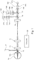
- Fig. 1 is a diagram illustrating an apparatus for determining refractive error of an eye 10 having optical properties represented by a lens 10A according to an embodiment.
- the apparatus of Fig. 1 includes an infrared laser 11 as an illumination device. Light from infrared laser 11 is reflected by a semitransparent mirror 12 through lens 10A into eye 10.
- the person examined i.e. the person to whom eye 10 belongs
- the person examined does not notice the examination.
- Focus adjustable lens 13 is a simple example for an optical power changing device and may be implemented as explained above, for example using an adjustable liquid lens, or any of the other possibilities mentioned above, including an arrangement of several lenses or other optical elements as well as moving lenses or detectors.
- the placement of focus adjustable lens 13 is also only an example, and as explained above other placements may be used.
- Lenses 14, 15 form a telescope arrangement guiding the light to a first semitransparent mirror 16 followed by a second semitransparent mirror 17.
- First semitransparent mirror 16 passes a part of the light to a first module 18A, and passes another part of the light on to semitransparent mirror 17.
- Semitransparent mirror 17 reflects part of the light to a second module 18B, and passes another part of the light on to a third module 18C.
- the amount of light provided to each of modules 18A to 18C may be approximately the same, but also may be different from each other.
- Each of first to third modules 18A to 18C comprises a respective aperture 19A, 19B, 19C, respectively, and a respective lens 20A, 20B, 20C, respectively, for passing light to a respective detector 21A, 21B, 21C, respectively.
- Apertures 19A, 19B and 19C are different from each other.
- Detectors 21A, 21B and 21C in the embodiment of Fig. 1 are photodiodes.
- Apertures 19A, 19B and 19C are examples for an aperture device and detectors 21A, 21B and 21C are examples for a detector device.
- module 18C may have an exchangeable aperture, such that three different apertures may be inserted consecutively.
- aperture 19C may be a rotatable aperture with a slit-shaped opening, as explained above.
- one of the modules 18A, 18B or 18C may be omitted.
- the apparatus of Fig. 1 additionally includes a computer 22.
- Computer 22 controls a focal setting of focus adjustable lens 13, receives detected intensities from detectors 21A, 21B and 21C, and calculates the refractive error of eye 10, more particularly of lens 10A thereof, in terms of sphere, cylinder and axis.
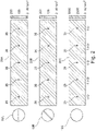
- FIG. 2 shows examples for apertures 19A, 19B and 19C and associated measurements.
- Aperture 19A has a slit running in a horizontal direction. This slit-shaped opening leads to a wide diffraction limited point spread function in one meridian of the eye (in this case perpendicular to the slit), and an aberration limited point spread function in the medium perpendicular thereto.
- a graph 25A shows resulting intensity distributions after the aperture for different optical power settings of focus adjustable lens 13 of -3 D, -1.5 D, 0 D, 1.5 D and 3 D.
- An optical power setting of 0 D corresponds to the case where the point spread function an emmetropic (aberration-free) eye is in focus on detectors 21A-21C.
- variable focus lens 13 is scanned through a range of optical power settings.
- Corresponding intensities are measured with photodiode 21A.
- the diameter of the photodiode is much smaller than the diffraction limited point spread function, for example at least 2 times smaller, at least 3 time smaller, or at least 5 times smaller.
- the detection area of the detectors 21A, 21B, 21C, respectively, is marked with reference numeral 26 throughout Fig. 2 .
- the maximum intensity is detected by photodiode 21A at the optical power setting of -1.5 D, which may be seen as a focal shift or defocus change in this case.
- the value for which this maximum is detected depends on the refractive error of the eye, in lens 10A and length, and therefore the maximum at -1.5 D is merely a specific example.
- Aperture 19B is also slit-shaped and the opening is tilted in an angle of 45° compared to the slit of aperture 19A.
- intensities are measured by photodiode 21B, with the maximum intensity in this case being measured at 0 D.
- Third aperture 19C has a round opening of a diameter similar to typical physiological eye pupil sizes.
- the intensity is detected by photodiode 21C.
- Photodiode 21C in this case has a diameter similar to the airy disc produced by the aperture 19C, the airy disc corresponding to a best focus spot of light that a perfect lens with the circular aperture 19C can make, limited by the diffraction of light.
- the photodiode size may be half the diameter of the airy disc ⁇ 50 %, preferably ⁇ 20 %.
- the maximum intensity is then detected at 0 D.
- variable focus lens 13 controls variable focus lens 13 to scan through a range of focus settings (in the example of Fig. 2 , from -3 D to 3 D in steps of 1.5 D), and computer 22 receives the intensities measured by detectors 21A, 21B and 21C and determines the focus setting where the intensity is at a maximum. In the example of Fig. 2 , as mentioned this would be at -1.5 D for aperture 19A, at 0 D for aperture 19B and at 0 D for aperture 19C.
- sphere directly follows from the maximum intensity for aperture 19C, i.e. is equal to M.
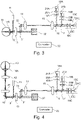
- a light path for visible light is added.
- a short pass mirror 31 is provided.
- Mirror 31 reflects only light in the infrared range, and let light in the visible range pass through.
- Such mirrors may for example be implemented by using respective coating layers.
- the light from infrared laser 11 as reflected by the retina of light 10 goes through to a mirror 30 and then to lenses 14, 15 already described.
- visible light from lenses 14, 15 and modules 18a to 18c does not come to eye 10, as it is not reflected by short stop mirror 31, and therefore these measurement components are not seen by the person examined.
- short pass mirror 31 is transparent to visible light, eye 10 may view the surroundings or other elements through short pass mirror 31. This may also be referred to as providing a visible channel or visible light path. This enables the refractive error measurement described above to be performed under natural viewing conditions for eye 10.
- a stimulus 32 is provided in this visible path to be viewed by the person during the measurement, to bring eye 10 to a certain accommodated state (for example focused on a nearby object if stimulus 32 is provided near eye 10, focus on a far object if stimulus 32 is provided farther away) or while varying the accommodation, by effectively moving stimulus 32.
- Effectively moving may include moving stimulus 32 itself, or providing a variable optic in front of stimulus 32. This additionally may help to reduce instrument myopia, thus leading to a higher accuracy of the measurement.
- a further focus adjustable lens may be provided in front of element 32.
- the refractive error during accommodation to a new distance may be measured.
- stimulus 32 may be an eye chart.
- This eye chart may be any conventional eye chart, for example Snellen chart, and may be displayed on a computer screen or provided on a wall to be viewed through short pass mirror 31.
- the apparatus of Fig. 3 may additionally be used as a phoropter, i.e. for subjective refractive error determination.
- the focal setting of variable focus lens 13 may be varied, and the person examined may indicated at which focal setting he/she can best see letters, numbers, symbols, etc. displayed on the eye chart.
- Fig. 4 illustrates a further embodiment.
- a scanning module 40 is provided in a conjugated plane to the pupil of eye 10, with respect to a telescope optic formed by lenses 41, 42.
- the scanning module is represented by a rotational mirror. Combinations of several mirrors or other optical elements may also be used.
- the focus spot light beam from infrared laser 11 may essentially be scanned over the retina of eye 10.
- the refractive error of the eye may be determined for a visual field of eye 10.
- a so-called peripheral refractive error for a periphery of the retina may be measured. This may for example be used for evaluating myopia development, see W. Neil Charman and H. Radhakrishnan, "Peripheral refraction and the development of refractive error: A review," Ophthalmic Physiol. Opt. 30, 321-338 (2010 ).
- Fig. 5 is a flowchart illustrating a method according to an embodiment.
- the method of Fig. 5 may be implemented using the apparatuses discussed with reference to Figs. 1 , 3 and 4 and in order to avoid repetitions, the method of Fig. 5 will be explained referring to the previous explanations.
- intensities of light from the eye are measured through at least two different apertures, for example through the three apertures 19A, 19B and 19C discussed previously. Without any additional information, at least three different apertures are used. In implementations where, as mentioned above, the axis (angle ⁇ in the formula above), or sphere (value M in the formula above) is known from other measurements, two apertures are sufficient.
- the intensities may be measured in step 50 depending on a focal setting of a focus adjustable lens like focus adjustable lens 13.
- step 51 the reflection of the eye is determined based on the intensities, for example by identifying at which focus setting the intensities are at their maximum for the respective aperture and then determining the refractive error based on these focus settings, as explained above referring to Fig. 2 .
- the determined refractive error may then be used for producing a lens for spectacle glasses based on the refractive error to correct the refractive error. To this end, the determined refractive error is transmitted to a lens manufacturer.
Landscapes
- Health & Medical Sciences (AREA)
- Life Sciences & Earth Sciences (AREA)
- Engineering & Computer Science (AREA)
- Medical Informatics (AREA)
- Surgery (AREA)
- Biophysics (AREA)
- Biomedical Technology (AREA)
- Heart & Thoracic Surgery (AREA)
- Physics & Mathematics (AREA)
- Molecular Biology (AREA)
- Ophthalmology & Optometry (AREA)
- Animal Behavior & Ethology (AREA)
- General Health & Medical Sciences (AREA)
- Public Health (AREA)
- Veterinary Medicine (AREA)
- Signal Processing (AREA)
- Eye Examination Apparatus (AREA)
Abstract
Apparatuses or methods for determining a refractive error of an eye are disclosed. An intensity of light coming from an eye (10) is measured through at least two different apertures (19A, 19B, 19C). The refractive error is then calculated based on the measured intensities.
Description
- The present application relates to apparatuses and methods for determining the refractive error of an eye.
- Determining the refractive error of an eye is an important part of eye examinations, the result of which is for example used to produce lenses for eyeglasses with appropriate optical properties for the respective eye or to prescribe appropriate contact lenses. In the field of ophthalmology, the refractive error of an eye is usually given in terms of sphere, also referred to as spherical power, as defined in 11.2 of DIN EN ISO 13666:2013-10, cylinder, or also referred to as cylindrical power, as defined under 12.5 of DIN EN ISO 13666:2013-10 and axis, more precisely cylinder axis, as defined under 12.6 of DIN EN ISO 13666:2013-10. These values give essentially the deviations from an emmetropic eye (zero refractive error). Values of 0 for sphere and cylinder indicate that the eye is emmetropic, while values different from 0 indicate various kinds of ametropia like hyperopia or myopia.
- A determination of the refractive error may be a subjective refractive error determination or objective refractive error determination. Methods for subjective refractive error determination are based on a (subjective) feedback of an examined person regarding his or her visual perception. An example is a measurement on the basis of eye charts with small and smaller symbols, letters, numbers or the like, where the person gives feedback which numbers, letters or symbols he or she can recognize. Lenses may then be placed in front of the eye of the person, and the person may give feedback with which lenses the best visual perception is obtained. An example for apparatuses allowing subjective refractive error determinations are phoropters. Methods and apparatuses for objective refractive error determination do not need such a feedback of the examined person regarding his or her visual perception.
- Examples for apparatuses for objective refractive error determination are Hartmann-Shack-based aberrometers, as for example described in G. Colicchia and H. Wiesner, Physics Education, . Such aberrometers are comparatively complex and therefore are costly apparatuses which require a camera and lenslet array for sensing wavefronts. The measurement range of such aberrometers is limited by the parameters of the lenslet array and is inversely proportional to the accuracy, i.e. a higher measurement range typically will result in lower accuracy.
- Another class of apparatuses used for objective refractive error determination are referred to as autorefractors are based on principles described in Spanish patent application
ES 482663 A1 Zeiss Visuref 100 or 150. Such autorefractors often exhibit a comparatively low accuracy compared to aberrometers, in particular in case of a positive refractive error, i.e. hyperopic subjects. Therefore, the result of such autorefractors is often only used as a starting point to then perform a subjective refractive error determination as a more exact measurement. - Furthermore, current solutions of aberrometers and autorefractors usually do not offer the possibility to include possibilities for such subjective refractive error determination without significant changes of the optical design. Finally, conventional aberrometers and autorefractors do not provide natural viewing conditions, i.e. the person has to look into the instrument and does not naturally perceive his or her surroundings. This may lead to so-called "instrument myopia", i.e. myopia measured because of the particular measurement conditions outside natural viewing conditions, which do not correspond to actual ametropia of the eye.
- Starting from such conventional apparatuses for objective refractive error determination and corresponding methods, it is an object of the present invention to provide apparatuses and methods which are capable of remedying at least some of the drawbacks above, in particular which may be designed for a large measurement range, may be easily designed to allow natural viewing conditions or allow integration of a subjective refractive error determination.
- An apparatus for determining the refractive error of an eye as defined in claim 1 and a method for determining the refractive error of an eye as defined in
claim 16 are provided. The dependent claims define further embodiments as well as a method for manufacturing lenses for spectacles. - According to a first aspect of the invention, an apparatus for determining a refractive error of an eye is provided, comprising:
- an aperture device, and
- a detector device configured to measure an intensity of light coming from the eye through the aperture device.
- The apparatus is characterized in that the aperture device is configured to provide at least two different apertures, the detector device is configured to measure the intensities of light for each of the at least two different apertures. Furthermore, the apparatus is characterized by further comprising a computing device configured to determine the refractive error based on the intensities for each of the at least two different apertures.
- An aperture is an optical element which is an opening where light may pass through. An aperture device as used herein is any device which provides one or more apertures. The aperture device is designed to block light in the parts other than opening(s). The term "aperture device" does not imply that the device has to be in one piece or in one location. For example, the at least two different apertures may be provided in two different locations simultaneously.
- Apertures are the same as or different from each other in terms of shape, arranged orientation or both. It should be noted that the at least two apertures, as will be explained later, need not be two physically separate apertures, but may also be a single physical aperture which can be arranged in various orientations.
- Likewise, a detector device refers to any device which is capable of measuring at least light intensity. It may be capable of measuring further properties of light, like a beam shape or shape of a focal spot of light falling on the detector device. For example, for measuring only the light intensity, a photodiode may be used. For measuring further properties, an image sensor as used in digital cameras or a camera itself may be used. As for the aperture device, the detector device needs not be provided in one piece, but may include separate detectors for each aperture.
- "Intensity" refers to the power or energy of the light beam. It may be measured as an integrated intensity over a detector area.
- The refractive error may be indicated as sphere, cylinder and axis as mentioned above.
- A computing device refers to any device capable of determining the refractive error based on calculations and, where necessary, of controlling the apparatus. Such a computing device may be implemented as a conventional computer program accordingly, with interfaces for example to the detector device, or other components described below, a microcontroller, application-specific integrated circuits (ASICs) or combinations of such components.
- With such an apparatus, the refractive error may be determined precisely with a compact device.
- Generally speaking, the detector device may be used to measure the intensity of a respective point spread function (PSF) or its approximation, specific for the respective aperture over the area of detector, and based on the intensities of the point spread function over the area of the detector, the refractive error may be determined. As will be explained below, in embodiments the area of the detector is selected to cover a limited area only, such that a comparatively small area of the point spread function is measured. The point spread function generally describes the response of an imaging system, which in this case includes the at least two apertures, to a point source. If a light source other than a point source is present, what is measured is an approximation of the point spread function.
- In some embodiments, the at least two different apertures may include at least three different apertures. With three different apertures, the refractive error in terms of sphere, cylinder and axis may be determined without further information or measurement.
- Alternatively, the cylinder axis value, i.e. the axis as defined under 12.6 of DIN EN ISO 13666:2013-10, may be determined in advance by conventional measurements, for example by using an eye chart with rays depicted under different angles and determining, by subjective feedback from the person, in which direction the rays appear sharpest. In this case, as the axis is given, two different apertures are sufficient to determine the remaining two values of sphere and cylinder. In other cases, for example a value of the sphere may be known from other measurements. Also in this case, measurement with two apertures are sufficient to determine the remaining values, namely cylinder and axis.
- It should be noted that the measurement may be repeated for more than three (in case of at least three different apertures) or more than two different apertures (in the case where e.g. axis or sphere is known in advance and only at least two different apertures are required), respectively. As is generally the case for measurements, making more measurements than required may help to reduce a measurement error.
- Preferably, the apparatus further comprises an optical power changing device which changes the optical power of the light path from the eye to the detector device. The optical power of the light path determines the size and focus how the light from the eye is imaged to the detector. In some embodiments, the optical power changing device may include a variable focus optic. A variable focus optic generally is an optical device the focal length of which may varied. Such a variable focus optic may for example comprise one or more lenses, a focal length of which may be varied. Such lenses may for example include a lens with electrically variable focus as discussed in K. Asatryan et al., Optics Express, Volume 18, No. 13, liquid lenses, or an optic with two or more lenses, some of which are movable with respect to other lenses. Other examples include lens- or mirror-based Badal systems (D. A. Atchison, A. Bradley, L. N. Thibos, and G. Smith, "Useful Variations of the Badal Optometer," Optom. Vis. Sci. 72, 279-284 (1995)), deformable mirrors, spatial light modulators (SLMs) or a set of polarization-dependent lenses.
- The variable focus optic may be placed at different locations in the light path, for example between the eye and the aperture device, or also between the aperture device and the detector device, or also inside the aperture device. When the two or more apertures are provided separately with separate detectors of the detector device, the variable focus optic may include separate components for each aperture/detector combination.
- Another example for an optical power changing device causes axial movement of fixed focal length lenses within the system, or of the detector device. A range through which the optical power of the optical power changing device can be varied corresponds to a measurement range of the apparatus. By providing on optical power changing device with a wide range of optical power settings, a correspondingly large measurement range may be easily obtained.
- For determining the refractive error of an eye, the computing device may control the optical power changing device to vary the optical power, while the intensities are measured for each of the at least two different apertures. Maximum values of the intensity may then be identified by the computing device, and the calculation may be based on optical power settings of the optical power changing device at the respective maximum intensity for each of the at least two apertures. A similar approach may be taken of the change of optical power is provided computationally. Also here, optical powers for each aperture where a maximum intensity is present in a detection area may be determined.
- In this case, simple integrated intensity measurements may be used. This enables the use of simple detectors in the detector device, for example one or more photodiodes.
- The at least two apertures may include at least one slit-shaped opening. A slit-shaped opening refers to a shape similar to or a slit which has a significantly longer length than width, for example a length at least three times, at least four times or at least five times the width. A length of the slit may be similar to the physiological diameter of human's pupil, of the order of 2 to 8 mm, and a width may be less than 1 mm, preferably less than 0.4 mm, more preferably less than 0.2 mm. Smaller widths generally increase measurement accuracy, but on the other hand such a slit-shaped opening provides a wide diffraction limited point spread function in the width direction of the slit, and an aberration limited point spread function in the length direction of the slit. As a detector, preferably a circular shaped photodiode with a diameter similar to a diameter of point spread function produced by an aberration-free human eye (for physiological pupil sizes) may be used, such that essentially the intensity determined by the aberration limited point spread function is measured. In embodiments, the diameter of the photodiode, or more generally a diameter of a detection used is much smaller than the diffraction limited point spread function, for example at least 2 times smaller, at least 3 time smaller, or at least 5 times smaller.
- "Diffraction limited" in this case means that the point spread function resulted is limited by diffraction phenomena at the aperture of the apparatus, or the eye. In contrast, "aberration limited" means that the point spread function is determined by aberrations/optical properties of the eye.
- In case at least three apertures are used as mentioned above, two slit-shaped openings which are arranged in different directions or orientations may be used, or, in other words, the slit-shaped openings lie in different orientations or directions may be used. With slit-shaped openings, in particular axis and/or cylinder may be measured.
- In addition, one of the at least two apertures may be in a round shape which is a circular aperture. The circular aperture has a diameter similar to typical physiological eye pupil sizes, i.e. in the range of 2 to 8 mm. Based on such a round shape, the sphere of the refractive error may be determined.
- In a particularly preferred embodiment, three apertures are used, a first aperture with a slit-shaped opening orientated in a horizontal direction (left/right direction of the head), a second aperture also with a slit-shaped opening wherein a length direction of the opening is arranged at an angle of 45 ° thereto, and a third aperture with the above-mentioned round shape. With the two slit-shaped openings, the optical power of the optical power changing device (or for computationally varied optical power) at the maximum essentially corresponds to the Jackson Cross cylinder components, with added spherical equivalent (L. N. Thibos, W. Wheeler, and D. Horner, "Power vectors: an application of Fourier analysis to the description and statistical analysis of refractive error," Optom. Vis. Sci. 75, 367-375 (1997)). With P0, P45, and M being the respective optical power settings in Dioptres (D) of the optical power provided by the optical power changing device or computationally varied optical power in the pupil plane of the eye in terms of a deviation from a 0 setting for the first second and third apertures, respectively, power vectors J0, J45 can be calculated according to


- From that, the cylinder J may be calculated according to


- The sphere corresponds to M.
- In an alternative embodiment, instead of the circular aperture as a third aperture, a third aperture with a slit-shaped opening at an angle of 90° with respect to the slit-shaped opening of the first aperture may be used. In that case, the first and second apertures are used as above to measure values P0 , P45 , and with the third aperture a value P90 is measured corresponding to an optical power at maximum intensity for the third aperture. For the calculations above, then for M an average value of P0 and P90 is taken (M = (P0 +P90)/2). Other apertures, for example with slit-shaped openings arranged at the angles other than 0°, 45° or 90°, may also be used. This may lead to more complex calculations or to reduced accuracy.
- The apparatus may further include an illumination device for creating a focal spot on the subject's retina through the measurement, which, when back-propagated, produces aperture-modified point spread functions (of the point corresponding to the focal spot) on the detector device. In case a non-point light source like a light emitting diode, LED, is used, the detector device measures essentially a superposition of all point spread functions of points of the light on the eye. This, as mentioned above, may be seen as an approximation of the point spread function and may also be used for measurements as described herein. Therefore, a point light source like a focused laser is not required. Preferably, the illumination device uses infrared light, in particular an infrared laser. In this way, the person examined does not notice the light used for the measurement. Such an illumination device may be placed at various parts of the apparatus, and light may be guided to the eye using elements like mirrors, including for example a semitransparent mirror, and/or lenses.
- However, due to chromatic aberration of the eye, the values of sphere, cylinder and axis thus calculated using infrared light differ from the values for visible light, for which lenses ultimately have to be designed. Therefore, a correction of this deviation due to chromatic aberration of the optical power of the eye as a function of wavelength may be performed in some embodiments, for which previously reported values of longitudinal chromatic aberrations may be used, such as in M. Vinas, C. Dorronsoro, D. Cortes, D. Pascual, and S. Marcos, "Longitudinal chromatic aberration of the human eye in the visible and near infrared from wavefront sensing, double-pass and psychophysics," Biomed. Opt. Express 23, 513-522 (2015). For instance, chromatic shift from 555nm to 780nm would be around 0.8 D. Then, for calculating the refraction values, 0.8 D should be subtracted from M, P0, and P45 as used in the equations above.
- The at least two different apertures may be provided in different manners. In some embodiments, at least partially separate light paths from the eye may be provided for each of the apertures, and each light path may include a detector of the detector device. "Partially separate" indicates that the light paths may have a common part, which then splits up for the separate light paths. In this case, the intensity measurement for the at least two apertures may be performed simultaneously, thus reducing the measurement duration. In other embodiments, the aperture device may be configured to accommodate exchangeable apertures, such that the at least two apertures may be provided temporarily one after the other. This may allow for a more compact design of the apparatus, as only a single light path with corresponding detector is needed, but this may also extend measurement time. In yet other embodiments, for example a rotatable aperture with a slit-shaped opening may be provided, and this the at least two apertures correspond to the slit-shaped opening in different rotation positions.
- The apparatus may further include a visible light path which may allow the eye to view surroundings of the person examined. Such a viewing path may be separated from the aperture device and detector device by a short pass mirror which allows only light used for measurement, for example infrared light, to be reflected, while visible light coming from the aperture device or the detector device is blocked, such that the person cannot see the aperture device and detector device. In some embodiments, a stimulus may be provided in the visible eye path to be viewed by the eye. This may determine an accommodation state of the eye for the measurement, i.e. a distance to which the eye is focused. In some embodiments, the stimulus may include an eye chart. This enables the apparatus additionally to be used as a phoropter, i.e. for subjective refractive error determination, for example by varying the focus, cylinder, or axis of the optical power changing device mentioned above and receiving feedback from the person at which focus setting he or she views the eye chart best.
- The detector device may include single photodiodes, for example one photodiode for measuring the intensity for each of the at least two different apertures in case of different light paths, or a single photodiode in case of exchangeable apertures or a rotating aperture. In this way, a cheap implementation of the detector device is possible. However, other kinds of detectors like cameras may also be used.
- In some embodiments, the apparatus may include a scanner module provided in a conjugate pupil plane of the eye. With such a scanner module, the retina of the eye may be scanned, i.e. the refractive error determination may be performed for different points of the retina. In this way, peripheral refractive error of the eye may be measured.
- According to another aspect, a corresponding method for determining a refractive error of an eye is provided, comprising measuring an intensity of light coming from the eye through an aperture device. The method is characterized in that the intensity of light is measured for at least two different apertures through which light is coming from the eye, and in that the method further comprises determining the refractive error based on the intensities for each of the two different apertures.
- The various variations, modifications and additions described for the apparatus may be applied to the method in a corresponding manner. For example, the method may include varying an optical power setting of an optical power changing device and then, determining, for each of the at least two apertures, a focus setting which the intensity is at a maximum, and determining the refractive error based on the focus settings.
- The thus determined refractive error may then be used for producing lenses using the refractive error, i.e. lenses to correct the refractive error of the eye.
- A computer program may also be provided which, when executed on a computing device, causes the computing device to control an apparatus as explained above to perform the method as explained above.
- Various embodiments will now be described referring to the attached drawings, wherein:
-
Fig. 1 is an apparatus for determining the refractive error of an eye according to an embodiment, -
Fig. 2 is a diagram showing apertures and measurement results to illustrate embodiments, -
Fig. 3 shows an apparatus for determining the refractive error of an eye according to a further embodiment, -
Fig. 4 shows an apparatus for determining the refractive error of an eye according to a further embodiment, -
Fig. 5 is a flowchart illustrating a method according to embodiment. -
Fig. 1 is a diagram illustrating an apparatus for determining refractive error of aneye 10 having optical properties represented by alens 10A according to an embodiment. - It should be noted that while single lenses are depicted in several instances in the following embodiments, these may be replaced by combinations of two or more lenses, or by other optical elements like diffractive elements having the same or similar optical function.
- The apparatus of
Fig. 1 includes aninfrared laser 11 as an illumination device. Light frominfrared laser 11 is reflected by asemitransparent mirror 12 throughlens 10A intoeye 10. - By using an infrared laser, or infrared light in general, the person examined (i.e. the person to whom
eye 10 belongs) does not notice the examination. - Light reflected from the retina of
eye 10 throughlens 10A passes throughsemitransparent mirror 12, a focusadjustable lens 13 and an opticsarrangement including lenses adjustable lens 13 is a simple example for an optical power changing device and may be implemented as explained above, for example using an adjustable liquid lens, or any of the other possibilities mentioned above, including an arrangement of several lenses or other optical elements as well as moving lenses or detectors. The placement of focusadjustable lens 13 is also only an example, and as explained above other placements may be used. -
Lenses semitransparent mirror 16 followed by a secondsemitransparent mirror 17. - First
semitransparent mirror 16 passes a part of the light to afirst module 18A, and passes another part of the light on tosemitransparent mirror 17.Semitransparent mirror 17 reflects part of the light to asecond module 18B, and passes another part of the light on to athird module 18C. The amount of light provided to each ofmodules 18A to 18C may be approximately the same, but also may be different from each other. - Each of first to
third modules 18A to 18C comprises arespective aperture respective lens respective detector Apertures Detectors Fig. 1 are photodiodes.Apertures detectors - As explained above, instead of three
modules example module 18C, withsemitransparent mirrors module 18C may have an exchangeable aperture, such that three different apertures may be inserted consecutively. In other embodiments, in thiscase aperture 19C may be a rotatable aperture with a slit-shaped opening, as explained above. - Furthermore, in cases where the cylinder axis or the sphere of the refractive error are already known, as explained above only two different apertures may be needed. In such embodiments, one of the
modules - The apparatus of
Fig. 1 additionally includes acomputer 22.Computer 22 controls a focal setting of focusadjustable lens 13, receives detected intensities fromdetectors eye 10, more particularly oflens 10A thereof, in terms of sphere, cylinder and axis. - To further illustrate such a measurement,
Fig. 2 shows examples forapertures -
Aperture 19A has a slit running in a horizontal direction. This slit-shaped opening leads to a wide diffraction limited point spread function in one meridian of the eye (in this case perpendicular to the slit), and an aberration limited point spread function in the medium perpendicular thereto. Agraph 25A shows resulting intensity distributions after the aperture for different optical power settings of focusadjustable lens 13 of -3 D, -1.5 D, 0 D, 1.5 D and 3 D. An optical power setting of 0 D corresponds to the case where the point spread function an emmetropic (aberration-free) eye is in focus ondetectors 21A-21C. For measurement,variable focus lens 13 is scanned through a range of optical power settings. Corresponding intensities are measured withphotodiode 21A. The diameter of the photodiode is much smaller than the diffraction limited point spread function, for example at least 2 times smaller, at least 3 time smaller, or at least 5 times smaller. To illustrate an example, the detection area of thedetectors reference numeral 26 throughoutFig. 2 . - In this example, the maximum intensity is detected by
photodiode 21A at the optical power setting of -1.5 D, which may be seen as a focal shift or defocus change in this case. The value for which this maximum is detected depends on the refractive error of the eye, inlens 10A and length, and therefore the maximum at -1.5 D is merely a specific example. -
Aperture 19B is also slit-shaped and the opening is tilted in an angle of 45° compared to the slit ofaperture 19A. Here, intensities are measured byphotodiode 21B, with the maximum intensity in this case being measured at 0 D. -
Third aperture 19C has a round opening of a diameter similar to typical physiological eye pupil sizes. The intensity is detected byphotodiode 21C.Photodiode 21C in this case has a diameter similar to the airy disc produced by theaperture 19C, the airy disc corresponding to a best focus spot of light that a perfect lens with thecircular aperture 19C can make, limited by the diffraction of light. In particular, the photodiode size may be half the diameter of the airy disc ±50 %, preferably ±20 %. In this example, the maximum intensity is then detected at 0 D. - As mentioned, for
measurement computer 22 controlsvariable focus lens 13 to scan through a range of focus settings (in the example ofFig. 2 , from -3 D to 3 D in steps of 1.5 D), andcomputer 22 receives the intensities measured bydetectors Fig. 2 , as mentioned this would be at -1.5 D foraperture 19A, at 0 D foraperture 19B and at 0 D foraperture 19C. With P0 being the optical power setting at the maximum intensity foraperture 19A, and P45 the optical power setting at the maximum intensity foraperture 19B, and M the optical power setting at the maximum intensity foraperture 19C as mentioned cylinder J and axis α may be calculated according to


- The sphere directly follows from the maximum intensity for
aperture 19C, i.e. is equal to M. In the example ofFig. 2 , 0 D may indicate that there is no spherical aberration, i.e. equivalent sphere = 0 D. - Next, additions to the embodiment of
Fig. 1 will be described referring toFigs 3 and 4 . Components already discussed with reference toFigs. 1 and2 bear the same reference numerals and thus will not be described again. In particular, apart from differences pointed out below, operation of the embodiments ofFigs. 3 and 4 is the same as for the embodiments ofFig. 1 . - In the embodiment of
Fig. 3 , a light path for visible light is added. To this end, ashort pass mirror 31 is provided.Mirror 31 reflects only light in the infrared range, and let light in the visible range pass through. Such mirrors may for example be implemented by using respective coating layers. In this way, the light frominfrared laser 11 as reflected by the retina oflight 10 goes through to amirror 30 and then tolenses lenses eye 10, as it is not reflected byshort stop mirror 31, and therefore these measurement components are not seen by the person examined. Furthermore, asshort pass mirror 31 is transparent to visible light,eye 10 may view the surroundings or other elements throughshort pass mirror 31. This may also be referred to as providing a visible channel or visible light path. This enables the refractive error measurement described above to be performed under natural viewing conditions foreye 10. - In the embodiment of
Fig. 3 , astimulus 32 is provided in this visible path to be viewed by the person during the measurement, to bringeye 10 to a certain accommodated state (for example focused on a nearby object ifstimulus 32 is provided neareye 10, focus on a far object ifstimulus 32 is provided farther away) or while varying the accommodation, by effectively movingstimulus 32. Effectively moving may include movingstimulus 32 itself, or providing a variable optic in front ofstimulus 32. This additionally may help to reduce instrument myopia, thus leading to a higher accuracy of the measurement. For changing the perceived distance ofstimulus 32, a further focus adjustable lens may be provided in front ofelement 32. - In this way, the refractive error during accommodation to a new distance may be measured.
- In some embodiments,
stimulus 32 may be an eye chart. This eye chart may be any conventional eye chart, for example Snellen chart, and may be displayed on a computer screen or provided on a wall to be viewed throughshort pass mirror 31. Using this eye chart, the apparatus ofFig. 3 may additionally be used as a phoropter, i.e. for subjective refractive error determination. As can be seen, no significant modifications to the apparatus are necessary for this, but compared toFig. 1 , onlyshort pass mirror 31,mirror 30 and eye chart asstimulus 32 are additionally provided. For subjective refractive error measurement, the focal setting ofvariable focus lens 13 may be varied, and the person examined may indicated at which focal setting he/she can best see letters, numbers, symbols, etc. displayed on the eye chart. -
Fig. 4 illustrates a further embodiment. In addition to the embodiment ofFig. 4 , ascanning module 40 is provided in a conjugated plane to the pupil ofeye 10, with respect to a telescope optic formed bylenses - In
Fig. 4 , the scanning module is represented by a rotational mirror. Combinations of several mirrors or other optical elements may also be used. - Via
scanning module 40, the focus spot light beam frominfrared laser 11 may essentially be scanned over the retina ofeye 10. In this way, the refractive error of the eye may be determined for a visual field ofeye 10. In particular, also a so-called peripheral refractive error for a periphery of the retina may be measured. This may for example be used for evaluating myopia development, see W. Neil Charman and H. Radhakrishnan, "Peripheral refraction and the development of refractive error: A review," Ophthalmic Physiol. Opt. 30, 321-338 (2010). -
Fig. 5 is a flowchart illustrating a method according to an embodiment. The method ofFig. 5 may be implemented using the apparatuses discussed with reference toFigs. 1 ,3 and 4 and in order to avoid repetitions, the method ofFig. 5 will be explained referring to the previous explanations. - At a
step 50 inFig. 5 , intensities of light from the eye are measured through at least two different apertures, for example through the threeapertures step 50 depending on a focal setting of a focus adjustable lens like focusadjustable lens 13. - In
step 51, the reflection of the eye is determined based on the intensities, for example by identifying at which focus setting the intensities are at their maximum for the respective aperture and then determining the refractive error based on these focus settings, as explained above referring toFig. 2 . - The determined refractive error may then be used for producing a lens for spectacle glasses based on the refractive error to correct the refractive error. To this end, the determined refractive error is transmitted to a lens manufacturer.
- Some embodiments are defined by the following clauses:
- Clause 1. An apparatus for determining a refractive error of an eye (10), comprising:
- an aperture device (19A, 19B, 19C), and
- a detector device (21A, 21B, 21C) configured to measure an intensity of light coming from the eye (10) through the aperture device,
- characterized in that
- the aperture device (19A, 19B, 19C) is configured to provide at least two different apertures,
- the detector device (21A, 21B, 21C) is configured to measure the intensities of light for each of the at least two different apertures, and
- the apparatus further comprises a computing device (22) configured to determine the refractive error based on the intensities of light for each of the at least two different apertures.
- Clause 2. The apparatus of clause 1, characterized in that the computing device (22) is configured to determine the refractive error based on intensity of light for two different apertures and a cylinder axis provided to the computing device (22).
-
Clause 3. The apparatus of clause 1, characterized in that the computing device (22) is configured to determine the refractive error based on intensity of light for each of at least three different apertures. - Clause 4. The apparatus of any one of clauses 1 to 3, characterized by further comprising at least one of:
- an optical power changing device (13), wherein the computing device (22) is configured to control the optical power changing device (13) to vary an optical power of a light path from the eye (10) to the detector device (21A, 21B, 21C) through a measurement range, or
- the computing device (22) being configured to computationally vary an optical power of a light path from the eye (10) to the detector device (21A, 21B, 21C) through a measurement range,
- and characterized in that the computing device (22) is further configured to determine optical power settings at a maximum intensity for each of the at least two apertures, and to determine the refractive error based on the optical power settings at maximum intensity.
- Clause 5. The apparatus of any one of clauses 1 to 4, characterized in that the at least two apertures comprise/are two slit-shaped openings arranged in different directions.
- Clause 6. The apparatus of any one of clauses 1 to 6, wherein one of the at least two apertures comprise/is a third aperture with a circular opening, wherein the computing device (22) is configured to determine a sphere of the refractive error based on the optical power setting at maximum intensity for the third aperture.
- Clause 7. The apparatus of clauses 4, 5, and 6 wherein a first slit-shaped opening of the two slit-shaped openings has a longitudinal direction of the slit in a horizontal direction with respect to the eye (10), a second slit-shaped opening of the two slit-shaped openings is arranged at an angle of 45° with respect to the longitudinal direction of the first slit-shaped opening, and wherein a cylinder J and an axis α are calculated according to:


- Clause 8. The apparatus of any one of clauses 1 to 7, wherein the apparatus comprises separate light paths for each of the at least two apertures, and wherein the detector device (21A, 21B, 21C) comprises separate detectors for each of the at least two apertures.
- Clause 9. The apparatus of any one of clauses 1 to 7, wherein the aperture device (19A, 19B, 19C) is configured to provide the at least two apertures as exchangeable apertures.
-
Clause 10. The apparatus of any one of clauses 1 to 7, wherein the aperture device (19A, 19B, 19C) is configured to provide the at least two apertures by rotating a slit-shaped opening. -
Clause 11. The apparatus of any one of clauses 1 to 11, wherein the apparatus further comprises a visible light path separate from the aperture device (19A, 19B, 19C) and the detector device (21A, 21B, 21C). -
Clause 13. The apparatus ofclause 12, further comprising a stimulus (32) in the visible light path to be viewed by the eye (10). -
Clause 14. The apparatus ofclause 13, wherein the stimulus (32) comprises an eye chart. -
Clause 15. The apparatus of any one of clauses 1 to 14, further comprising a scanning module (40) arranged at a conjugate pupil plane to a pupil of the eye (10) and configured to scan a visual field of the eye (10). -
Clause 16. A method for determining a refractive error of an eye (10), comprising: measuring an intensity of light coming through the eye (10) through an aperture device (19A, 19B, 19C),
characterized in that
measuring an intensity of light coming from the eye (10) through the aperture device (19A, 19B, 19C) comprises measuring intensities of light coming from the eye (10) for each of at least two different apertures, and
the method further comprises determining the refractive error based on the intensities for each of the at least two different apertures. -
Clause 17. The method ofclause 16, characterized in that determining the refractive error is based on intensities for two different apertures and a provided cylinder axis. - Clause 18. The method of
clause 16, characterized in that determining the refractive error based on intensities for each of at least three different apertures. - Clause 19. The method of any one of
clauses 16 to 18, characterized by further comprising at least one of:- varying an optical power of a light path from the eye (10) to a detector device (21A, 21B, 21C) for the detecting through a measurement range, or
- computationally varying an optical power of a light path from the eye (10) to the detector device (21A, 21B, 21C) through a measurement range,
- and by determining optical power settings at a maximum intensity for each of the at least two apertures, and determining the refractive error based on the optical power settings at maximum intensity.
- Clause 20. The method of any one of
clauses 16 to 19, characterized in that the at least two apertures comprise/are two slit-shaped openings arranged in different directions. - Clause 21. The method of any one of
clauses 16 to 20, wherein the at least two apertures comprise/is a third aperture with a circular opening, the method further comprising determining a sphere of the refractive error based on the optical power setting at maximum intensity for the third aperture. -
Clause 22. The method of clauses 19, 20 and 21 wherein a first slit-shaped opening of the two slit-shaped openings has a longitudinal direction of the slit in a horizontal direction with respect to the eye (10), a second slit-shaped opening of the two slit-shaped openings is arranged at an angle of 45° with respect to the longitudinal direction of the slit-shaped opening of the first slit-shaped opening , and wherein a cylinder J and an axis α are calculated according to:


- Clause 23. The method of any one of
clauses 16 to 22, further comprising providing a stimulus (32) in a visible light path to be viewed by the eye (10). - Clause 24. The method of any one of
clauses 16 to 23, further comprising scanning a visual field of the eye (10). - Clause 25. A method for producing a lens for spectacle glasses, comprising:
- determining the refractive error of an eye (10) according to the method of any one of
clauses 16 to 24, and - producing the lens based on the determined refractive error.
- determining the refractive error of an eye (10) according to the method of any one of
Claims (15)
- An apparatus for determining a refractive error of an eye (10), comprising:an aperture device (19A, 19B, 19C), anda detector device (21A, 21B, 21C) configured to measure an intensity of light coming from the eye (10) through the aperture device,characterized in thatthe aperture device (19A, 19B, 19C) is configured to provide at least two different apertures,the detector device (21A, 21B, 21C) is configured to measure the intensities of light for each of the at least two different apertures, andthe apparatus further comprises a computing device (22) configured to determine the refractive error based on the intensities of light for each of the at least two different apertures.
- The apparatus of claim 1, characterized in that the computing device (22) is configured to determine the refractive error based on the intensities of light for two different apertures and a cylinder axis provided to the computing device (22).
- The apparatus of claim 1, characterized in that the computing device (22) is configured to determine the refractive error based on the intensities of light for each of at least three different apertures.
- The apparatus of any one of claims 1 to 3, characterized by further comprising at least one of:an optical power changing device (13), wherein the computing device (22) is configured to control the optical power changing device (13) to vary an optical power of a light path from the eye (10) to the detector device (21A, 21B, 21C) through a measurement range, orthe computing device (22) being configured to computationally vary an optical power of a light path from the eye (10) to the detector device (21A, 21B, 21C) through a measurement rangeand characterized in that the computing device (22) is further configured to determine optical power settings at a maximum intensity for each of the at least two apertures, and to determine the refractive error based on the optical power settings at maximum intensity.
- The apparatus of any one of claims 1 to 4, characterized in that the at least two apertures are two slit-shaped openings arranged in different directions.
- The apparatus of any one of claims 1 to 5, wherein one of the at least two apertures is a third aperture with a circular opening, wherein the computing device (22) is configured to determine a sphere of the refractive error based on optical power setting at maximum intensity for the third aperture.
- The apparatus of claim 5 or 6 wherein a first slit-shaped opening of the two slit-shaped openings has a longitudinal direction of the slit in a horizontal direction with respect to the eye (10), a second slit-shaped opening of the two slit-shaped openings is arranged at an angle of 45° with respect to the longitudinal direction of the first slitshaped opening, and wherein a cylinder J and an axis α are calculated according to:


- The apparatus of any one of claims 1 to 7, wherein the apparatus comprises separate light paths for each of the at least two apertures, and wherein the detector device (21A, 21B, 21C) comprises separate detectors for each of the at least two apertures.
- The apparatus of any one of claims 1 to 7, wherein the aperture device (19A, 19B, 19C) is configured to provide the at least two apertures as exchangeable apertures.
- The apparatus of any one of claims 1 to 7, wherein the aperture device (19A, 19B, 19C) is configured to provide the at least two apertures by rotating of a slit-shaped opening.
- The apparatus of any one of claims 1 to 10, wherein the apparatus further comprises a visible light path separate from the aperture device (19A, 19B, 19C) and the detector device (21A, 21B, 21C).
- The apparatus of claim 11, further comprising a stimulus (32) in the visible light path to be viewed by the eye (10).
- The apparatus of any one of claims 1 to 12, further comprising a scanning module (40) arranged at a conjugate pupil plane to a pupil of the eye (10) and configured to scan visual field of the eye (10).
- A method for determining a refractive error of an eye (10), comprising:measuring an intensity of light coming through the eye (10) through an aperture device (19A, 19B, 19C),characterized in thatmeasuring an intensity of light coming from the eye (10) through the aperture device (19A, 19B, 19C) comprises measuring intensities of light coming from the eye (10) for each of at least two different apertures, andthe method further comprises determining the refractive error based on the intensities for each of the at least two different apertures.
- A method for producing a lens for spectacle glasses, comprising:
determining the refractive error of an eye (10) according to the method of claim 14, and producing the lens based on the determined refractive error.
Priority Applications (5)
| Application Number | Priority Date | Filing Date | Title |
|---|---|---|---|
| EP20198056.2A EP3973849A1 (en) | 2020-09-24 | 2020-09-24 | Apparatus and method for determining the refractive error of an eye |
| CN202180065092.XA CN116390682B (en) | 2020-09-24 | 2021-09-24 | Device and method for determining refractive error of an eye |
| EP21798562.1A EP4216799B1 (en) | 2020-09-24 | 2021-09-24 | Apparatus and method for determining the refractive error of an eye |
| PCT/EP2021/000112 WO2022063423A2 (en) | 2020-09-24 | 2021-09-24 | Apparatus and method for determining the refractive error of an eye |
| US18/181,671 US11849997B2 (en) | 2020-09-24 | 2023-03-10 | Apparatus and method for determining the refractive error of an eye |
Applications Claiming Priority (1)
| Application Number | Priority Date | Filing Date | Title |
|---|---|---|---|
| EP20198056.2A EP3973849A1 (en) | 2020-09-24 | 2020-09-24 | Apparatus and method for determining the refractive error of an eye |
Publications (1)
| Publication Number | Publication Date |
|---|---|
| EP3973849A1 true EP3973849A1 (en) | 2022-03-30 |
Family
ID=72644167
Family Applications (2)
| Application Number | Title | Priority Date | Filing Date |
|---|---|---|---|
| EP20198056.2A Withdrawn EP3973849A1 (en) | 2020-09-24 | 2020-09-24 | Apparatus and method for determining the refractive error of an eye |
| EP21798562.1A Active EP4216799B1 (en) | 2020-09-24 | 2021-09-24 | Apparatus and method for determining the refractive error of an eye |
Family Applications After (1)
| Application Number | Title | Priority Date | Filing Date |
|---|---|---|---|
| EP21798562.1A Active EP4216799B1 (en) | 2020-09-24 | 2021-09-24 | Apparatus and method for determining the refractive error of an eye |
Country Status (4)
| Country | Link |
|---|---|
| US (1) | US11849997B2 (en) |
| EP (2) | EP3973849A1 (en) |
| CN (1) | CN116390682B (en) |
| WO (1) | WO2022063423A2 (en) |
Citations (4)
| Publication number | Priority date | Publication date | Assignee | Title |
|---|---|---|---|---|
| US4293198A (en) * | 1977-09-21 | 1981-10-06 | Canon Kabushiki Kaisha | Eye refractometer |
| US4376573A (en) * | 1979-03-20 | 1983-03-15 | Canon Kabushiki Kaisha | Apparatus for measuring the refractive power of the eye |
| WO2007033326A2 (en) * | 2005-09-14 | 2007-03-22 | Welch Allyn, Inc. | Medical apparatus comprising and adaptive lens |
| WO2013165689A1 (en) * | 2012-04-30 | 2013-11-07 | Clarity Medical Systems, Inc. | Ophthalmic wavefront sensor operating in parallel sampling and lock-in detection mode |
Family Cites Families (10)
| Publication number | Priority date | Publication date | Assignee | Title |
|---|---|---|---|---|
| ES482663A0 (en) | 1979-07-19 | 1980-11-01 | Antonio Medina Puerta | ELECTRONIC REFRACTOMETER |
| FR2546055B1 (en) * | 1983-05-19 | 1986-04-11 | Essilor Int | REFRACTOMETRY METHOD AND DEVICE FOR MEASURING THE DEGREE OF AMETROPIA AND IN PARTICULAR THE DEGREE OF ASTIGMATISM OF AN EYE |
| US4820037A (en) * | 1985-01-10 | 1989-04-11 | Canon Kabushiki Kaisha | Apparatus for measuring the refractive power of an eye |
| DE69729701T2 (en) * | 1996-10-03 | 2005-07-07 | Nidek Co., Ltd., Gamagori | Device for measuring the refraction of an eye |
| US7445335B2 (en) * | 2006-01-20 | 2008-11-04 | Clarity Medical Systems, Inc. | Sequential wavefront sensor |
| US8100530B2 (en) * | 2006-01-20 | 2012-01-24 | Clarity Medical Systems, Inc. | Optimizing vision correction procedures |
| US7780294B2 (en) * | 2006-03-23 | 2010-08-24 | Amo Manufacturing Usa, Llc. | Systems and methods for wavefront reconstruction for aperture with arbitrary shape |
| EP2077747A1 (en) * | 2006-10-16 | 2009-07-15 | Karan Aggarwala | Apparatus and method for subjective determination of the refractive error of the eye |
| US9456746B2 (en) * | 2013-03-15 | 2016-10-04 | Carl Zeiss Meditec, Inc. | Systems and methods for broad line fundus imaging |
| US10117574B2 (en) * | 2015-01-09 | 2018-11-06 | Smart Vision Labs, Inc. | Portable wavefront aberrometer with open field alignment channel |
-
2020
- 2020-09-24 EP EP20198056.2A patent/EP3973849A1/en not_active Withdrawn
-
2021
- 2021-09-24 WO PCT/EP2021/000112 patent/WO2022063423A2/en not_active Ceased
- 2021-09-24 CN CN202180065092.XA patent/CN116390682B/en active Active
- 2021-09-24 EP EP21798562.1A patent/EP4216799B1/en active Active
-
2023
- 2023-03-10 US US18/181,671 patent/US11849997B2/en active Active
Patent Citations (4)
| Publication number | Priority date | Publication date | Assignee | Title |
|---|---|---|---|---|
| US4293198A (en) * | 1977-09-21 | 1981-10-06 | Canon Kabushiki Kaisha | Eye refractometer |
| US4376573A (en) * | 1979-03-20 | 1983-03-15 | Canon Kabushiki Kaisha | Apparatus for measuring the refractive power of the eye |
| WO2007033326A2 (en) * | 2005-09-14 | 2007-03-22 | Welch Allyn, Inc. | Medical apparatus comprising and adaptive lens |
| WO2013165689A1 (en) * | 2012-04-30 | 2013-11-07 | Clarity Medical Systems, Inc. | Ophthalmic wavefront sensor operating in parallel sampling and lock-in detection mode |
Non-Patent Citations (6)
| Title |
|---|
| D. A. ATCHISONA. BRADLEYL. N. THIBOSG. SMITH: "Useful Variations of the Badal Optometer", OPTOM. VIS. SCI., vol. 72, pages 279 - 284 |
| G. COLICCHIAH. WIESNER, PHYSICS EDUCATION, vol. 41, no. 4 |
| K. ASATRYAN ET AL., OPTICS EXPRESS, vol. 18, no. 13 |
| L. N. THIBOSW. WHEELERD. HORNER: "Power vectors: an application of Fourier analysis to the description and statistical analysis of refractive error", OPTOM. VIS. SCI., vol. 75, 1997, pages 367 - 375 |
| M. VINASC. DORRONSOROD. CORTESD. PASCUALS. MARCOS: "Longitudinal chromatic aberration of the human eye in the visible and near infrared from wavefront sensing, double-pass and psychophysics", BIOMED. OPT. EXPRESS, vol. 23, 2015, pages 513 - 522 |
| W. NEIL CHARMANH. RADHAKRISHNAN: "Peripheral refraction and the development of refractive error: A review", OPHTHALMIC PHYSIOL. OPT., vol. 30, 2010, pages 321 - 338 |
Also Published As
| Publication number | Publication date |
|---|---|
| EP4216799A2 (en) | 2023-08-02 |
| WO2022063423A2 (en) | 2022-03-31 |
| EP4216799B1 (en) | 2025-12-17 |
| US20230210361A1 (en) | 2023-07-06 |
| EP4216799C0 (en) | 2025-12-17 |
| CN116390682B (en) | 2024-06-21 |
| CN116390682A (en) | 2023-07-04 |
| WO2022063423A3 (en) | 2022-05-12 |
| US11849997B2 (en) | 2023-12-26 |
Similar Documents
| Publication | Publication Date | Title |
|---|---|---|
| US6761454B2 (en) | Apparatus and method for determining objective refraction using wavefront sensing | |
| US7490940B2 (en) | Method for determining objective refraction using wavefront sensing | |
| US8033664B2 (en) | Apparatus and method for determining sphere and cylinder components of subjective refraction using objective wavefront measurement | |
| EP2079355B1 (en) | Eyeglass prescription method and system | |
| EP2833778B1 (en) | Objective phoropter system | |
| WO2002032299A1 (en) | Optical characteristics measuring device | |
| JP2008246153A (en) | Optometry apparatus and method thereof | |
| EP4216799B1 (en) | Apparatus and method for determining the refractive error of an eye | |
| EP4298988B1 (en) | Apparatus and method for determining the refractive error of an eye | |
| US5532772A (en) | Ophthalmic apparatus with positioning control | |
| WO2015107373A1 (en) | Ophthalmic apparatus | |
| US20210015356A1 (en) | Optometer for Home Use | |
| US20240407641A1 (en) | Optometer for home use | |
| Anjos | Development of a fundus camera for analysis of photoreceptor directionality in the healthy retina | |
| dos Santos Anjos | Development of a fundus camera for analysis of photoreceptor directionality in the healthy retina | |
| WO2015049632A1 (en) | Apparatus and method for measuring aberrations of the optical system of a living being |
Legal Events
| Date | Code | Title | Description |
|---|---|---|---|
| PUAI | Public reference made under article 153(3) epc to a published international application that has entered the european phase |
Free format text: ORIGINAL CODE: 0009012 |
|
| STAA | Information on the status of an ep patent application or granted ep patent |
Free format text: STATUS: REQUEST FOR EXAMINATION WAS MADE |
|
| 17P | Request for examination filed |
Effective date: 20200924 |
|
| AK | Designated contracting states |
Kind code of ref document: A1 Designated state(s): AL AT BE BG CH CY CZ DE DK EE ES FI FR GB GR HR HU IE IS IT LI LT LU LV MC MK MT NL NO PL PT RO RS SE SI SK SM TR |
|
| STAA | Information on the status of an ep patent application or granted ep patent |
Free format text: STATUS: THE APPLICATION IS DEEMED TO BE WITHDRAWN |
|
| 18D | Application deemed to be withdrawn |
Effective date: 20221001 |