EP3973821B1 - Chair device and star-shaped base thereof - Google Patents
Chair device and star-shaped base thereof Download PDFInfo
- Publication number
- EP3973821B1 EP3973821B1 EP20809209.8A EP20809209A EP3973821B1 EP 3973821 B1 EP3973821 B1 EP 3973821B1 EP 20809209 A EP20809209 A EP 20809209A EP 3973821 B1 EP3973821 B1 EP 3973821B1
- Authority
- EP
- European Patent Office
- Prior art keywords
- center seat
- star
- shaped base
- extending
- extending arms
- Prior art date
- Legal status (The legal status is an assumption and is not a legal conclusion. Google has not performed a legal analysis and makes no representation as to the accuracy of the status listed.)
- Active
Links
Images


Classifications
-
- A—HUMAN NECESSITIES
- A47—FURNITURE; DOMESTIC ARTICLES OR APPLIANCES; COFFEE MILLS; SPICE MILLS; SUCTION CLEANERS IN GENERAL
- A47C—CHAIRS; SOFAS; BEDS
- A47C7/00—Parts, details, or accessories of chairs or stools
- A47C7/002—Chair or stool bases
- A47C7/004—Chair or stool bases for chairs or stools with central column, e.g. office chairs
-
- A—HUMAN NECESSITIES
- A47—FURNITURE; DOMESTIC ARTICLES OR APPLIANCES; COFFEE MILLS; SPICE MILLS; SUCTION CLEANERS IN GENERAL
- A47C—CHAIRS; SOFAS; BEDS
- A47C3/00—Chairs characterised by structural features; Chairs or stools with rotatable or vertically-adjustable seats
- A47C3/02—Rocking chairs
- A47C3/025—Rocking chairs with seat, or seat and back-rest unit, elastically mounted in a rigid frame
-
- A—HUMAN NECESSITIES
- A47—FURNITURE; DOMESTIC ARTICLES OR APPLIANCES; COFFEE MILLS; SPICE MILLS; SUCTION CLEANERS IN GENERAL
- A47C—CHAIRS; SOFAS; BEDS
- A47C7/00—Parts, details, or accessories of chairs or stools
- A47C7/002—Chair or stool bases
- A47C7/006—Chair or stool bases with castors
-
- A—HUMAN NECESSITIES
- A47—FURNITURE; DOMESTIC ARTICLES OR APPLIANCES; COFFEE MILLS; SPICE MILLS; SUCTION CLEANERS IN GENERAL
- A47C—CHAIRS; SOFAS; BEDS
- A47C9/00—Stools for specified purposes
- A47C9/002—Stools for specified purposes with exercising means or having special therapeutic or ergonomic effects
Definitions
- the disclosure relates to a chair device and a star-shaped base thereof, and particularly to a base used for office chairs, work chairs, stools, or standing auxiliary equipment.
- the chair device has a chair column, which may be adjusted in height.
- a supporting structure on the chair column for placing a seat surface.
- the supporting structure includes, for example, a foundation support, a chair support, and, if necessary, a backrest support.
- the star-shaped base is usually applied to a swivel chair, a swivel stool, or a chair.
- the seat surface of the devices may rotate around the longitudinal axis of the chair column.
- the so-called “movable chairs” are now vigorously promoted from an ergonomic point of view.
- the posture, such as the tilt, of such chair device may be changed along with the load on the chair device and/or changes in the load, especially when the user of the chair device sits at different positions of the chair device or when the center of gravity of the user changes due to movement.
- the chair device is designed to be rotatable or swingable in all directions. For this reason, structural transformations are often performed on existing chair devices or supporting structures with good performance.
- the mechanical solution produced in this way is not only more complicated, but also requires high costs to manufacture.
- changes in the design of the chair device or the supporting structure will become worse.
- the objective of the disclosure is to provide a chair device that can rotate or swing without changing existing parts, especially a supporting structure of a chair seat or a seat surface, on top of a chair column of the chair device.
- US 2008/106132 A1 discloses a rocker seat comprising a seat part, at least one leg part, at least one foot assembly including a plurality of foot elements and at least one first spring arrangement, and at least one particular of the foot elements and/or a subelement thereof is provided movably and is subjected to the action of a resilient return moment upon loading thereof.
- a foot device for a piece of seating furniture with a seat, at least one at least partially vertically movable foot element, an intermediate piece arranged between the seat and the foot element, and with a pivotable roller device arranged on the foot element, with a substantially vertical pivot axis, and with a control device which always keeps the pivot axis in a vertical position during a vertical movement of the at least one foot element.
- a core idea of the disclosure is to implement the rotation and the swing of a chair seat or a seat surface through modifying parts below the chair column of the chair device. As such, a movable star-shaped base is provided.
- the star-shaped base of the disclosure is characterized in that among extending arms mounted on a center seat of the star-shaped base, at least one extending arm is hinged to the center seat and may rotate relative to the center seat.
- a chair of the disclosure is characterized in that the chair is provided with the star-shaped base.
- the star-shaped base with the extending arms that may rotate relative to the center seat can implement changes in position of the center seat, which include lowering of the center seat in a vertical direction and tilting of the center seat relative to a horizontal plane, that is, tilting relative to the ground. Therefore, in the chair device, all parts arranged above the center seat and supported by the center seat and the chair column fixed on the center seat, including the supporting structure and the chair, may implement rotation or swing in addition to lowering movement without specially designing the supporting structure.
- the extending arm mounted on the center seat of the star-shaped base is usually fixed with a roller. Through the roller, the chair device may move on the ground. Although the chair device may implement very safe and stable standing on the ground by means of the star-shaped base, the star-shaped base with rollers still has the following situations: the chair device may accidentally move or roll on the ground, even when the user is sitting on the chair device. Even though the rolling of the chair device is usually small, such accidental movement may still pose a danger. In other words, the user may fall or be injured due to such accidental rolling of the chair device or the user may be disturbed due to such movement of the chair device while sitting. When the user of the chair device is an elderly, the dangers are more prominent.
- the solution of the disclosure can avoid the accidental rolling or the accidental movement of the chair device.
- the chair device here refers to the type in which the extending arm of the star-shaped base is provided with the roller.
- the solution is that when the seat surface of the chair device is loaded due to the user, the center seat of the star-shaped base may be lowered to the ground due to the rotatability of the extending arm. Since the user applies a force on the chair, a static friction generated by the force on the center seat can avoid the accidental rolling or the accidental movement of the chair.
- the static friction here is greater than a rolling friction required for rolling.
- Such simple method can provide a safe chair or stool, which is attractive to the elderly.
- such chair may also be used applied to a workplace. In the workplace, the accidental movement of the chair interferes with work, but due to the need to move, the chair must be used.
- chairs in the form of standing auxiliary devices are also more common.
- the standing auxiliary devices are rarely provided with the star-shaped base.
- the roller is rarely mounted on the foundation of the standing auxiliary device.
- On the standing auxiliary device such "movable chair” is usually implemented by: mounting a joint close to the ground, so that the foundation supporting the seat surface may rotate.
- the disclosure makes it possible to implement a new type of standing auxiliary device.
- the auxiliary device when the seat surface is fully loaded, the center seat of the star-shaped base is lowered to the ground to form a supporting point and a rotating point of the standing auxiliary device.
- Such state where the extending arm is firmly supported on the ground ensures that the standing auxiliary device is in a very safe state.
- the extending arm with limited deflection also limits the rotation of the standing auxiliary device, thereby avoiding an undesirable extreme state of the standing auxiliary device, which may cause fall and injury.
- the disclosure may be used not only on office chairs, work chairs, and stools, but also on standing auxiliary devices.
- each solution may contribute to the solution of the disclosure independently or in combination with each other.
- each extending arm rotatable relative to the center seat :
- the number of extending arms hinged to the center seat and rotating relative to the center seat is at least such that: when the extending arms simultaneously rotate, the center seat may be lowered to an extent of contacting the ground. Therefore, if the force of the load on the chair device is ensured to be sufficiently large, the center seat may be lowered to the ground, and the chair device may be used as the standing auxiliary device.
- a bottom surface of the center seat that is, a surface of the center seat facing the ground, is manufactured into a convex surface.
- a convex supporting surface is preferably a spherical surface. Such spherical surface support enables the center seat lowered on the ground to easily implement the required rotation and swing.
- all of the extending arms are hinged to the center seat and may rotate relative to the center seat.
- the number of extending arms may be 4 or 6, but preferably 5.
- each extending arm that rotates relative to the center seat resists an elastic force of an elastic element when rotating.
- each extending arm that rotates relative to the center seat is provided with the elastic element.
- the elastic element acts between the extending arm and the center seat, that is, one end of the elastic element acts on the extending arm and the other end acts on the center seat.
- the elastic element may be a compression spring or an elastic block designed according to geometric conditions and made of an elastic material.
- an independent elastic element such as a circular elastic block, may also be configured.
- Such elastic element may be easily mounted around the center seat.
- the chair device When using the elastic element, due to an elastic action thereof, the chair device generates useful rotation and swing, and erect or reset behavior. If there is a load on the chair device, such as the user sitting on the chair device, the elastic action will provide a limiting resistance. The user of the chair device must resist the elastic force under the action of the load to move the chair device. Once the load on the chair device changes, such as due to the movement of the user on the seat surface or changes in position of the center of gravity of the user, the elastic action will provide a limiting rotational resistance. The user of the chair device must resist the elastic force when rotating or swinging in order to move the chair device. At the same time, according to the increase or decrease of the applied force, a corresponding elastic action is generated.
- the elastic force for support may restore the movement of the center seat to the starting position. If the load on the chair device completely disappears, that is, the chair device is unloaded, such as due to the user standing up, the center seat of the star-shaped base and the seat surface will automatically restore to an upright position.
- the roller is preferably mounted at the free end of the extending arm.
- the star-shaped base may move.
- a substitute of the roller may be a sliding part or other similar parts.
- the rotation of a single or all extending arms, or the lowering and tilting functions of the center seat may all be locked by means of a locking device.
- the locking device is designed such that: a locking action is used to simultaneously lock the rotation of all of the extending arms from the starting position of the extending arm. Therefore, the star-shaped base assembled according to the disclosure may be used as a conventional non-movable base according to requirements.
- the locking occurs through a mechanical way.
- the preferred way is to at least partially fill a rotation space necessary for the rotation of the extending arm through the movement of a suitable locking element, and then perform mechanical locking, or lock an inward rotation of the extending arm in the rotation space through other ways.
- a chair device of the disclosure may be any one of an office chair, a work chair, a stool, or a standing auxiliary equipment.
- a stool is used as an example for description.
- a stool 1 stands on a ground 2 through a foundation thereof.
- the foundation is designed as a star-shaped base 3.
- the star-shaped base 3 includes a center seat 4 (also referred to as a "hub") and five extending arms 5 mounted on the center seat. The extending arms are uniformly distributed along the center seat.
- a roller 6 is fixed to a free end of the extending arm 5.
- the height of the chair column 8 may be adjusted by means of a gas spring (not shown in the drawings).
- the supporting structure includes a foundation support 10 and a chair support 12.
- the foundation support 10 and a conical accommodating member 11 are placed on the chair column 8.
- the chair support 12 is connected to the foundation support 10.
- the chair support 12 and the seat surface 9 are rotatable around a rotation axis of a longitudinal axis 13 of the chair column.
- All of the five extending arms 5 mounted on the center seat respectively have rotary joints that are hinged to the center seat 4 and rotate relative to the center seat 4.
- a rotation axis 14 shown in FIG. 2 is illustrative of direction and is parallel to a supporting surface 15 of the roller 6.
- Each extending arm 5 is independently connected to the center seat 4 and rotates without being affected by the other extending arms 5.
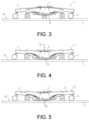
- the extending arm 5 may rotate from an unrotated starting position shown in FIG. 3 and FIG. 4 to a maximum deflection position shown in FIG. 5 and may restore the rotation.
- a maximum rotation position and a degree of deflection of the extending arm 5 are determined by a stopper block 16 on the center seat 4.
- the feature of the structure is that the extending arm 5 is stably placed on the supporting surface 15, that is, supported on the ground 2, which does not depend on whether the seat surface 9 is loaded or whether the center seat 4 is lowered and/or tilted.
- the extending arm 5 rotates relative to the center seat 4 in such a way that: during an entire rotating process, the free end of the extending arm 5 maintains a ground clearance. The free end maintains contact with the ground through the roller 6 or similar components.
- the structure is designed such that when the center seat 4 is lowered, the contact between the extending arm 5 and the ground may be maintained while the extending arm 5 rotates relative to the center seat 4. Depending on the degree of deflection of each extending arm 5, the center seat 4 may be lowered, even to an extent of contacting the ground 2.
- a bottom surface of the center seat facing the ground 2 is made into a convex surface to form an arch-shaped grindable supporting surface 17.
- the center seat 4 may grind along the supporting surface. In this way, in a completely lowered state, the chair device may rotate or swing.
- each extending arm 5 is provided with an elastic element.
- an elastic element 18 of the extending arm 5 is only symbolically represented as a compression spring. The placement of the elastic element enables the elastic element to work between one end of the extending arm 5 and the other end of the center seat 4. Once the load on the extending arm 5 disappears or decreases, the elastic element 18 may pull the extending arm 5 from a rotation position back to the starting position.
- an annular locking element 21 mounted on the center seat 4 By means of an annular locking element 21 mounted on the center seat 4, the rotation of all of the extending arms 5 may be simultaneously locked.
- the locking element may rotate around the rotation axis in a direction of the longitudinal axis 13 of the chair column relative to a center seat base from a middle position (see FIG. 6 ) to a locked position.
- a braking element (not shown in the drawings) mounted on the locking element 21 is guided to a back surface 22 of the extending arm 5.
- the back surface faces the center seat 4.
- the main thing is that a rotation space 19 is simultaneously embedded.
- a mechanical connection that transmits force is formed at least in an immediate area between the back surface 22 and the stopper block 16. As a result, the movement of the extending arm 5 rotating to the rotation space 19 and the rotation of the extending arm 5 are blocked.
- the extending arm 5 may rotate relative to the center seat 4.
- the rotation space 19 provides a free spacing 20.
- One side of the spacing is the back surface 22 of the extending arm 5, and the other side is the stopper block 16 mounted inside the center seat. The spacing determines a maximum degree of deflection.
- FIG. 3 shows the star-shaped base 3 of the stool 1 when the seat surface 9 is not loaded.
- the rollers 6 are all on the ground.
- the grindable supporting surface 17 on the bottom surface of the center seat is spaced from the ground 2.
- the spacing between the lowest point of the bottom surface of the center seat and the ground 2 is preferably only a few centimeters.
- the center seat 4 moves along a vertical direction without tilting toward a horizontal direction.
- the center seat 4 is vertically lowered to the ground 2 along a lowering direction 23, as shown in FIG. 4 .
- all of the extending arms 5 will be deflected upward along a deflection direction 28 in the same way, especially the same route.
- the rollers 6 are always supported on the ground 2.
- the extending arm 5 plays a role of further support to ensure that the stool 1 safely stands.
- the seat surface 9 bears a non-uniform load and may rotate or swing (as shown by an arrow 24 in FIG. 1 ).
- the center seat 4, which is still on the ground 2 will be tilted relative to the vertical direction (as shown in FIG. 5 and FIG. 6 ). According to a tilting direction, some extending arms 5 will rotate more, while other extending arms 5 will rotate less. When the center seat 4 not yet contacts the ground, such tilting of the center seat 4 may also occur.
- the extending arm 5 may be further deflected upward.
- the roller 6 still maintains contact with the ground, that is, the roller 6 will always be on the ground and become an additional supporting surface.
- the center seat 4 According to an action direction of the force of the load exerted by the user on the stool 1 and taking into account a restoring force provided by the elastic element 18, the center seat 4 will be tilted to different degrees in different spatial directions, which means that the extending arm 5 mounted on the center seat 4 will deflect with different intensities.
- FIG. 5 shows a case where the center seat is lowered and tilted.
- FIG. 6 is a cross-sectional view when the extending arm is in the middle position with less rotation in the case.
- the lowering and the tilting of the center seat 4 may be simultaneously performed. If the center seat 4 is lowered to the ground, the center seat 4 may still be further tilted.
- the lowering movement and the tilting movement of the center seat 4 and the rotation and the swing of the seat surface 9 are limited through the elastic force of the elastic element 18 mounted on the extending arm 5.
- a lowering path of the center seat 4 or a rotating path of the extending arm 5 and a restoring braking force of each elastic element 18 that participates due to the movement of the center seat 4 show a linear relationship.
- the tilting movement of the center seat 4 and the rotation and the swing of the seat surface 9 may be limited, which may be implemented through setting a maximum deflection of the extending arm 5.
- the extending arm 5 reaches the maximum deflection, the extending arm 5 abuts the stopper block 16 provided on the center seat 4.
- the stopping of the lowering movement is not implemented through the extending arm 5 contacting the center seat 4, but through the center seat 4 being lowered to the ground 2.
- the disclosure relates to the star-shaped base on the chair device, which may be used in office chairs, work chairs, stools, or standing auxiliary devices in particular.
- the seat surface 9 may rotate or swing without changing the parts, especially the supporting structure 10, the chair support 12 where the seat surface 9 is mounted, the seat surface.
- the rotation or the swing of the seat surface 9 may be achieved by: modifying the parts of the chair device 1 mounted below the chair column 8, that is, mounting the movable star-shaped base 3.
- the star-shaped base 3 is characterized in that at least one of the extending arms 5 mounted on the center seat 4 is hinged to the center seat 4 and may rotate relative to the center seat 4.
- the center seat has multiple extensions respectively extending outward.
- the extensions are disposed in a one-to-one correspondence with the extending arms. At least one or all of the extending arms are respectively hinged to the corresponding extensions on the center seat.
- An elastic element is disposed between the extending arm and the corresponding extension. The elastic element provides the elastic force resisting the rotation of the extending arm relative to the center seat.
- Other structures are disposed with reference to the above embodiment.
- At least one or all of the extending arms are also connected to the center seat through a connecting rod, so that a crank slider mechanism is formed between the extending arm, the connecting rod, and the center seat.
- One end of the connecting rod is hinged to the center seat, and the other end of the connecting rod is slidably connected to the extending arm.
- one end of the connecting rod is hinged to the extending arm, and the other end of the connecting rod is slidably connected to the center seat.
- an elastic element preferably a compression spring or a tension spring
- the elastic element provides the elastic force resisting the rotation of the extending arm relative to the center seat.
- At least one or all of the extending arms are also connected to the center seat through two connecting rods, so that a planar four-bar mechanism is formed between the extending arm, the two connecting rods, and the center seat.
- An elastic element preferably a compression spring or a tension spring
- the elastic element provides the elastic force resisting the rotation of the extending arm relative to the center seat.
- the number of extending arms of the star-shaped base may be 3, 4, 5, 6, or more than 6, but preferably 5.
Landscapes
- Chairs Characterized By Structure (AREA)
- Chair Legs, Seat Parts, And Backrests (AREA)
- Special Chairs (AREA)
Description
- The disclosure relates to a chair device and a star-shaped base thereof, and particularly to a base used for office chairs, work chairs, stools, or standing auxiliary equipment.
- Nowadays, for chair devices, especially office chairs, work chairs, and stools, star-shaped bases are the standard solution for the foundation. Usually, the chair device has a chair column, which may be adjusted in height. There is a supporting structure on the chair column for placing a seat surface. The supporting structure includes, for example, a foundation support, a chair support, and, if necessary, a backrest support. The star-shaped base is usually applied to a swivel chair, a swivel stool, or a chair. The seat surface of the devices may rotate around the longitudinal axis of the chair column.
- Regardless of the existing movable and adjustable chairs, the so-called "movable chairs" are now vigorously promoted from an ergonomic point of view. The posture, such as the tilt, of such chair device may be changed along with the load on the chair device and/or changes in the load, especially when the user of the chair device sits at different positions of the chair device or when the center of gravity of the user changes due to movement. In this respect, the chair device is designed to be rotatable or swingable in all directions. For this reason, structural transformations are often performed on existing chair devices or supporting structures with good performance. However, the mechanical solution produced in this way is not only more complicated, but also requires high costs to manufacture. Generally speaking, due to the need to add necessary components and provide necessary space, changes in the design of the chair device or the supporting structure will become worse.
- The objective of the disclosure is to provide a chair device that can rotate or swing without changing existing parts, especially a supporting structure of a chair seat or a seat surface, on top of a chair column of the chair device.
-
US 2008/106132 A1 discloses a rocker seat comprising a seat part, at least one leg part, at least one foot assembly including a plurality of foot elements and at least one first spring arrangement, and at least one particular of the foot elements and/or a subelement thereof is provided movably and is subjected to the action of a resilient return moment upon loading thereof. -
DE 10 2009 007324 A1 discloses a foot device for a piece of seating furniture, with a seat, at least one at least partially vertically movable foot element, an intermediate piece arranged between the seat and the foot element, and with a pivotable roller device arranged on the foot element, with a substantially vertical pivot axis, and with a control device which always keeps the pivot axis in a vertical position during a vertical movement of the at least one foot element. - The objective can be implemented through the star-shaped base and the chair device described in the independent claims of the disclosure. Preferred embodiments are provided in the dependent claims.
- A core idea of the disclosure is to implement the rotation and the swing of a chair seat or a seat surface through modifying parts below the chair column of the chair device. As such, a movable star-shaped base is provided.
- The star-shaped base of the disclosure is characterized in that among extending arms mounted on a center seat of the star-shaped base, at least one extending arm is hinged to the center seat and may rotate relative to the center seat. A chair of the disclosure is characterized in that the chair is provided with the star-shaped base.
- According to a first aspect of the disclosure, the star-shaped base with the extending arms that may rotate relative to the center seat can implement changes in position of the center seat, which include lowering of the center seat in a vertical direction and tilting of the center seat relative to a horizontal plane, that is, tilting relative to the ground. Therefore, in the chair device, all parts arranged above the center seat and supported by the center seat and the chair column fixed on the center seat, including the supporting structure and the chair, may implement rotation or swing in addition to lowering movement without specially designing the supporting structure.
- The extending arm mounted on the center seat of the star-shaped base is usually fixed with a roller. Through the roller, the chair device may move on the ground. Although the chair device may implement very safe and stable standing on the ground by means of the star-shaped base, the star-shaped base with rollers still has the following situations: the chair device may accidentally move or roll on the ground, even when the user is sitting on the chair device. Even though the rolling of the chair device is usually small, such accidental movement may still pose a danger. In other words, the user may fall or be injured due to such accidental rolling of the chair device or the user may be disturbed due to such movement of the chair device while sitting. When the user of the chair device is an elderly, the dangers are more prominent.
- According to a second aspect of the disclosure, the solution of the disclosure can avoid the accidental rolling or the accidental movement of the chair device. The chair device here refers to the type in which the extending arm of the star-shaped base is provided with the roller. The solution is that when the seat surface of the chair device is loaded due to the user, the center seat of the star-shaped base may be lowered to the ground due to the rotatability of the extending arm. Since the user applies a force on the chair, a static friction generated by the force on the center seat can avoid the accidental rolling or the accidental movement of the chair. The static friction here is greater than a rolling friction required for rolling. Such simple method can provide a safe chair or stool, which is attractive to the elderly. At the same time, such chair may also be used applied to a workplace. In the workplace, the accidental movement of the chair interferes with work, but due to the need to move, the chair must be used.
- In addition, from the technical point of view, chairs in the form of standing auxiliary devices are also more common. The standing auxiliary devices are rarely provided with the star-shaped base. The roller is rarely mounted on the foundation of the standing auxiliary device. On the standing auxiliary device, such "movable chair" is usually implemented by: mounting a joint close to the ground, so that the foundation supporting the seat surface may rotate.
- According to a third aspect of the disclosure, the disclosure makes it possible to implement a new type of standing auxiliary device. In the auxiliary device, when the seat surface is fully loaded, the center seat of the star-shaped base is lowered to the ground to form a supporting point and a rotating point of the standing auxiliary device. Such state where the extending arm is firmly supported on the ground ensures that the standing auxiliary device is in a very safe state. At the same time, the extending arm with limited deflection also limits the rotation of the standing auxiliary device, thereby avoiding an undesirable extreme state of the standing auxiliary device, which may cause fall and injury.
- Therefore, the disclosure may be used not only on office chairs, work chairs, and stools, but also on standing auxiliary devices.
- In a preferred embodiment of the disclosure, each solution may contribute to the solution of the disclosure independently or in combination with each other. According to the preferred embodiment of the disclosure, each extending arm rotatable relative to the center seat:
- a) is connected to the center seat. The extending arms may independently rotate without being affected by each other;
- b) may rotate from an unrotated starting position to a maximum extent and may also be reset;
- c) rotates relative to the center seat in such a way that: during an entire rotating process, a free end of the extending arm maintains a ground clearance.
and/or - d) rotates relative to the center seat in such a way that: when the center seat is lowered, the extending arm maintains contact with the ground.
- In addition, according to another preferred embodiment of the disclosure, the number of extending arms hinged to the center seat and rotating relative to the center seat is at least such that: when the extending arms simultaneously rotate, the center seat may be lowered to an extent of contacting the ground. Therefore, if the force of the load on the chair device is ensured to be sufficiently large, the center seat may be lowered to the ground, and the chair device may be used as the standing auxiliary device.
- According to a preferred embodiment of the disclosure, a bottom surface of the center seat, that is, a surface of the center seat facing the ground, is manufactured into a convex surface. A convex supporting surface is preferably a spherical surface. Such spherical surface support enables the center seat lowered on the ground to easily implement the required rotation and swing.
- According to a particularly preferred embodiment of the disclosure, all of the extending arms are hinged to the center seat and may rotate relative to the center seat. According to the preferred embodiment of the disclosure, the number of extending arms may be 4 or 6, but preferably 5.
- According to a preferred embodiment of the disclosure, each extending arm that rotates relative to the center seat resists an elastic force of an elastic element when rotating.
- According to a preferred embodiment of the disclosure, each extending arm that rotates relative to the center seat is provided with the elastic element. The elastic element acts between the extending arm and the center seat, that is, one end of the elastic element acts on the extending arm and the other end acts on the center seat. In simple cases, the elastic element may be a compression spring or an elastic block designed according to geometric conditions and made of an elastic material.
- As such, an independent elastic element, such as a circular elastic block, may also be configured. Such elastic element may be easily mounted around the center seat.
- When using the elastic element, due to an elastic action thereof, the chair device generates useful rotation and swing, and erect or reset behavior. If there is a load on the chair device, such as the user sitting on the chair device, the elastic action will provide a limiting resistance. The user of the chair device must resist the elastic force under the action of the load to move the chair device. Once the load on the chair device changes, such as due to the movement of the user on the seat surface or changes in position of the center of gravity of the user, the elastic action will provide a limiting rotational resistance. The user of the chair device must resist the elastic force when rotating or swinging in order to move the chair device. At the same time, according to the increase or decrease of the applied force, a corresponding elastic action is generated. The elastic force for support may restore the movement of the center seat to the starting position. If the load on the chair device completely disappears, that is, the chair device is unloaded, such as due to the user standing up, the center seat of the star-shaped base and the seat surface will automatically restore to an upright position.
- According to a preferred embodiment of the disclosure, the roller is preferably mounted at the free end of the extending arm. By means of the rollers, the star-shaped base may move. A substitute of the roller may be a sliding part or other similar parts.
- According to the present invention, the rotation of a single or all extending arms, or the lowering and tilting functions of the center seat may all be locked by means of a locking device. The locking device is designed such that: a locking action is used to simultaneously lock the rotation of all of the extending arms from the starting position of the extending arm. Therefore, the star-shaped base assembled according to the disclosure may be used as a conventional non-movable base according to requirements.
- According to the disclosure, the locking occurs through a mechanical way. The preferred way is to at least partially fill a rotation space necessary for the rotation of the extending arm through the movement of a suitable locking element, and then perform mechanical locking, or lock an inward rotation of the extending arm in the rotation space through other ways.
- The embodiments of the disclosure can be better explained by means of the following drawings.
-
FIG. 1 is a chair device with a star-shaped base. -
FIG. 2 is a perspective view of a star-shaped base. -
FIG. 3 is a side view of an unloaded star-shaped base. -
FIG. 4 is a side view of a uniformly loaded star-shaped base. -
FIG. 5 is a side view of a non-uniformly loaded star-shaped base. -
FIG. 6 is a detailed cross-sectional view of the side view ofFIG. 5 . - All the drawings are not intended to show the disclosure to scale, but are schematic views and only contain basic components. The same reference numerals represent the same elements or elements with similar functions.
-
- 1. chair device, stool
- 2. ground
- 3. star-shaped base
- 4. center seat
- 5. extending arm
- 6. roller
- 7. accommodating sleeve
- 8. chair column
- 9. seat surface
- 10. foundation support
- 11. conical accommodating member
- 12. chair support
- 13. longitudinal axis of chair column
- 14. rotation axis
- 15. supporting surface
- 16. stopper block
- 17. grindable supporting surface, bottom surface of center seat
- 18. elastic element, compression spring
- 19. rotation space
- 20. free spacing
- 21. locking element
- 22. back surface of extending arm
- 23. lowering direction
- 24. rotation and swing direction
- 25. guide groove
- 26. guide pin
- 27. vertical direction
- 28. deflection direction
- A chair device of the disclosure may be any one of an office chair, a work chair, a stool, or a standing auxiliary equipment. In the embodiment, a stool is used as an example for description. A
stool 1 stands on aground 2 through a foundation thereof. The foundation is designed as a star-shapedbase 3. The star-shapedbase 3 includes a center seat 4 (also referred to as a "hub") and five extendingarms 5 mounted on the center seat. The extending arms are uniformly distributed along the center seat. Aroller 6 is fixed to a free end of the extendingarm 5. There is anaccommodating sleeve 7 for a chair column 8 in the middle of the center seat 4. The height of the chair column 8 may be adjusted by means of a gas spring (not shown in the drawings). - There is a supporting structure for placing a
seat surface 9 on the chair column 8. In the simple example shown here, the supporting structure includes a foundation support 10 and achair support 12. The foundation support 10 and a conical accommodatingmember 11 are placed on the chair column 8. Thechair support 12 is connected to the foundation support 10. There is thefinal seat surface 9 with a cushion on thechair support 12. Thechair support 12 and theseat surface 9 are rotatable around a rotation axis of a longitudinal axis 13 of the chair column. - All of the five extending
arms 5 mounted on the center seat respectively have rotary joints that are hinged to the center seat 4 and rotate relative to the center seat 4. Arotation axis 14 shown inFIG. 2 is illustrative of direction and is parallel to a supportingsurface 15 of theroller 6. - Each extending
arm 5 is independently connected to the center seat 4 and rotates without being affected by the other extendingarms 5. The extendingarm 5 may rotate from an unrotated starting position shown inFIG. 3 and FIG. 4 to a maximum deflection position shown inFIG. 5 and may restore the rotation. As shown inFIG. 6 , a maximum rotation position and a degree of deflection of the extendingarm 5 are determined by astopper block 16 on the center seat 4. - The feature of the structure is that the extending
arm 5 is stably placed on the supportingsurface 15, that is, supported on theground 2, which does not depend on whether theseat surface 9 is loaded or whether the center seat 4 is lowered and/or tilted. In other words, the extendingarm 5 rotates relative to the center seat 4 in such a way that: during an entire rotating process, the free end of the extendingarm 5 maintains a ground clearance. The free end maintains contact with the ground through theroller 6 or similar components. The structure is designed such that when the center seat 4 is lowered, the contact between the extendingarm 5 and the ground may be maintained while the extendingarm 5 rotates relative to the center seat 4. Depending on the degree of deflection of each extendingarm 5, the center seat 4 may be lowered, even to an extent of contacting theground 2. - A bottom surface of the center seat facing the
ground 2 is made into a convex surface to form an arch-shapedgrindable supporting surface 17. When the center seat 4 contacts the ground, the center seat 4 may grind along the supporting surface. In this way, in a completely lowered state, the chair device may rotate or swing. - When the extending
arm 5 rotates relative to the center seat 4, the extendingarm 5 needs to resist an elastic force of an elastic element. Each extendingarm 5 is provided with an elastic element. InFIG. 6 , anelastic element 18 of the extendingarm 5 is only symbolically represented as a compression spring. The placement of the elastic element enables the elastic element to work between one end of the extendingarm 5 and the other end of the center seat 4. Once the load on the extendingarm 5 disappears or decreases, theelastic element 18 may pull the extendingarm 5 from a rotation position back to the starting position. - By means of an annular locking element 21 mounted on the center seat 4, the rotation of all of the extending
arms 5 may be simultaneously locked. The locking element may rotate around the rotation axis in a direction of the longitudinal axis 13 of the chair column relative to a center seat base from a middle position (seeFIG. 6 ) to a locked position. A braking element (not shown in the drawings) mounted on the locking element 21 is guided to aback surface 22 of the extendingarm 5. The back surface faces the center seat 4. The main thing is that arotation space 19 is simultaneously embedded. A mechanical connection that transmits force is formed at least in an immediate area between theback surface 22 and thestopper block 16. As a result, the movement of the extendingarm 5 rotating to therotation space 19 and the rotation of the extendingarm 5 are blocked. There is an arc-shapedguide groove 25 on the locking element 21 close to the center seat 4, and aguide pin 26 mounted on the center seat base is embedded therein. In therotation space 19, the extendingarm 5 may rotate relative to the center seat 4. Therotation space 19 provides afree spacing 20. One side of the spacing is theback surface 22 of the extendingarm 5, and the other side is thestopper block 16 mounted inside the center seat. The spacing determines a maximum degree of deflection. -
FIG. 3 shows the star-shapedbase 3 of thestool 1 when theseat surface 9 is not loaded. Therollers 6 are all on the ground. Thegrindable supporting surface 17 on the bottom surface of the center seat is spaced from theground 2. The spacing between the lowest point of the bottom surface of the center seat and theground 2 is preferably only a few centimeters. - When the
seat surface 9 is uniformly loaded, the center seat 4 moves along a vertical direction without tilting toward a horizontal direction. When the force of the load on the seat surface is sufficiently large, the center seat 4 is vertically lowered to theground 2 along a loweringdirection 23, as shown inFIG. 4 . At the same time, all of the extendingarms 5 will be deflected upward along adeflection direction 28 in the same way, especially the same route. Therollers 6 are always supported on theground 2. - When the user not only causes the
seat surface 9 to move down, but also to rotate or swing, the rolling of thestool 1 is avoided due to a friction effect of the spherical bottom surface of the center seat when grinding. The extendingarm 5 plays a role of further support to ensure that thestool 1 safely stands. - When the position of the center of gravity of the user changes, the
seat surface 9 bears a non-uniform load and may rotate or swing (as shown by anarrow 24 inFIG. 1 ). The center seat 4, which is still on theground 2, will be tilted relative to the vertical direction (as shown inFIG. 5 andFIG. 6 ). According to a tilting direction, some extendingarms 5 will rotate more, while other extendingarms 5 will rotate less. When the center seat 4 not yet contacts the ground, such tilting of the center seat 4 may also occur. When theseat surface 9 is non-uniformly loaded or the deflection or the swing relative to the vertical direction is very strong, the extendingarm 5 may be further deflected upward. Nevertheless, theroller 6 still maintains contact with the ground, that is, theroller 6 will always be on the ground and become an additional supporting surface. According to an action direction of the force of the load exerted by the user on thestool 1 and taking into account a restoring force provided by theelastic element 18, the center seat 4 will be tilted to different degrees in different spatial directions, which means that the extendingarm 5 mounted on the center seat 4 will deflect with different intensities.FIG. 5 shows a case where the center seat is lowered and tilted.FIG. 6 is a cross-sectional view when the extending arm is in the middle position with less rotation in the case. - The lowering and the tilting of the center seat 4 may be simultaneously performed. If the center seat 4 is lowered to the ground, the center seat 4 may still be further tilted.
- The lowering movement and the tilting movement of the center seat 4 and the rotation and the swing of the
seat surface 9 are limited through the elastic force of theelastic element 18 mounted on the extendingarm 5. A lowering path of the center seat 4 or a rotating path of the extendingarm 5 and a restoring braking force of eachelastic element 18 that participates due to the movement of the center seat 4 show a linear relationship. At the same time, the tilting movement of the center seat 4 and the rotation and the swing of theseat surface 9 may be limited, which may be implemented through setting a maximum deflection of the extendingarm 5. When the extendingarm 5 reaches the maximum deflection, the extendingarm 5 abuts thestopper block 16 provided on the center seat 4. The stopping of the lowering movement is not implemented through the extendingarm 5 contacting the center seat 4, but through the center seat 4 being lowered to theground 2. - The disclosure relates to the star-shaped base on the chair device, which may be used in office chairs, work chairs, stools, or standing auxiliary devices in particular. In order to provide the chair device 1: the
seat surface 9 may rotate or swing without changing the parts, especially the supporting structure 10, thechair support 12 where theseat surface 9 is mounted, the seat surface. The rotation or the swing of theseat surface 9 may be achieved by: modifying the parts of thechair device 1 mounted below the chair column 8, that is, mounting the movable star-shapedbase 3. The star-shapedbase 3 is characterized in that at least one of the extendingarms 5 mounted on the center seat 4 is hinged to the center seat 4 and may rotate relative to the center seat 4. - In other embodiments, the center seat has multiple extensions respectively extending outward. The extensions are disposed in a one-to-one correspondence with the extending arms. At least one or all of the extending arms are respectively hinged to the corresponding extensions on the center seat. An elastic element is disposed between the extending arm and the corresponding extension. The elastic element provides the elastic force resisting the rotation of the extending arm relative to the center seat. Other structures are disposed with reference to the above embodiment.
- In other embodiments, in addition to being hinged to the center seat, at least one or all of the extending arms are also connected to the center seat through a connecting rod, so that a crank slider mechanism is formed between the extending arm, the connecting rod, and the center seat. One end of the connecting rod is hinged to the center seat, and the other end of the connecting rod is slidably connected to the extending arm. Alternatively, one end of the connecting rod is hinged to the extending arm, and the other end of the connecting rod is slidably connected to the center seat. In addition, an elastic element (preferably a compression spring or a tension spring) is disposed between any two of the connecting rod, the extending arm, and the center seat. The elastic element provides the elastic force resisting the rotation of the extending arm relative to the center seat. Other structures are disposed with reference to the above embodiment.
- In other embodiments, in addition to being hinged to the center seat, at least one or all of the extending arms are also connected to the center seat through two connecting rods, so that a planar four-bar mechanism is formed between the extending arm, the two connecting rods, and the center seat. An elastic element (preferably a compression spring or a tension spring) is disposed between any two of the extending arm, the two connecting rods, and the center seat. The elastic element provides the elastic force resisting the rotation of the extending arm relative to the center seat. Other structures are disposed with reference to the above embodiment.
- In the various embodiments above, the number of extending arms of the star-shaped base may be 3, 4, 5, 6, or more than 6, but preferably 5.
- All the features described in the specification, appended claims, and drawings, either independent or in any combination thereof, are important features of the disclosure.
- In the description of the specification, description with reference to terms such as "an embodiment", "some embodiments", "an implementation", "a specific implementation", "other implementations", "examples", "specific examples", or "some examples" means that the specific features, structures, materials, or characteristics described in conjunction with the embodiments or the examples are included in at least one embodiment, implementation, or example of the disclosure. In the specification, the schematic representations of the above terms do not necessarily refer to the same embodiment or example. Moreover, the specific features, structures, materials, or characteristics described above may also be combined in any one or more embodiments, implementations, or examples in a suitable manner. The technical solution recited in the disclosure also includes any one or more of the specific features, structures, materials, or characteristics described above independently or in combination.
- Although the embodiments of the disclosure have been shown and described above, it can be understood that the above embodiments are exemplary and should not be construed as limiting the disclosure. Persons skilled in the art may change, modify, replace, transform, delete some features, add features, or recombine features within the scope of the disclosure without departing from the scope of the present claims. Any simple modification, equivalent changes, and revisions made to the above embodiments according to the innovative principle of the disclosure still fall within the scope of the technical solution of the disclosure.
Claims (13)
- A star-shaped base (3) for a chair device, comprising a center seat (4) and a plurality of extending arms (5) mounted on the center seat (4), the extending arms being used to place the star-shaped base (3) on a ground, wherein: at least one of the extending arms (5) is hinged to the center seat (4) and rotates relative to the center seat (4),wherein rotation of one or all of the extending arms (5) is locked by a locking element (21);characterized in thatthe locking element (21) is an annular locking element mounted on the center seat (4), rotation of all of the extending arms (5) are simultaneously locked; when the locking element (21) rotates around a longitudinal axis (13) direction of a chair column relative to the center seat (4) to a locked position, a braking element on the locking element (21) is embedded between the center seat (4) and the extending arms (5), thereby blocking the rotation of the extending arms (5) relative to the center seat (4).
- The star-shaped base (3) according to claim 1, characterized in that: each of the extending arms (5) rotatable relative to the center seat is independently and rotatably connected onto the center seat (4) without being affected by other extending arms (5).
- The star-shaped base (3) according to claim 1, characterized in that:each of the extending arms (5) rotatable relative to the center seat (4) can rotate from a starting position to a maximum rotatable position and be restored; andeach of the extending arms (5) rotatable relative to the center seat (4) rotates relative to the center seat (4) in such a way that: during an entire rotating process, free ends of the extending arms (5) maintain ground clearance; andeach of the extending arms (5) rotatable relative to the center seat (4) rotates relative to the center seat (4) in such a way that: when the center seat (4) is lowered, the extending arms (5) maintain contact with the ground; andat least a plurality of the extending arms (5) are hinged on the center seat (4) and are rotatable relative to the center seat (4), so that when the extending arms (5) simultaneously rotate, the center seat (4) is lowered to an extent of contacting the ground (2).
- The star-shaped base (3) according to claim 1, characterized in that: five of the extending arms (5) are all mounted on the center seat (4);all of the extending arms (5) are hinged to the center seat (4) and are rotatable relative to the center seat (4);a bottom surface (17) of the center seat is made into a convex shape;a free end of the extending arm (5) is fixed with a roller (6).
- The star-shaped base (3) according to any one of claims 1 to 4, characterized in that:
each of the extending arms (5) rotatable relative to the center seat (4) needs to resist an elastic force of an elastic element (18) when rotating. - The star-shaped base (3) according to claim 5, characterized in that: one end of the elastic element (18) acts on the extending arm (5), and other end of the elastic element (18) acts on the center seat (4).
- The star-shaped base (3) according to claim 6, characterized in that the elastic element (18) is a compression spring.
- The star-shaped base (3) according to claim 1, characterized in that: the locking element (21) is provided with an arc-shaped guide groove (25), and a guide pin (26) mounted on the center seat (4) is embedded in the guide groove (25).
- The star-shaped base (3) according to any one of claims 1 to 4, characterized in that:
the center seat has a plurality of extensions respectively extending outward, the extensions are disposed in one-to-one correspondence with the extending arms, at least one or all of the extending arms are respectively hinged to the corresponding extensions, an elastic element is disposed between the extending arm and the corresponding extension, the elastic element provides an elastic force resisting rotation of the extending arm relative to the center seat. - The star-shaped base (3) according to any one of claims 1 to 4, characterized in that:
the extending arm is further connected to the center seat through a plurality of connecting rods. - The star-shaped base (3) according to claim 10, characterized in that: the extending arm is further connected to the center seat through a connecting rod, so that a crank slider mechanism is formed between the extending arm, the connecting rod, and the center seat; one end of the connecting rod is hinged to the center seat, other end of the connecting rod is slidably connected to the extending arm, or one end of the connecting rod is hinged to the extending arm, other end of the connecting rod is slidably connected to the center seat; and an elastic element is disposed between any two of the connecting rod, the extending arm, and the center seat, and the elastic element provides an elastic force resisting rotation of the extending arm relative to the center seat.
- The star-shaped base (3) according to claim 10, characterized in that: the extending arm is further connected to the center seat through two connecting rods, so that a planar four-bar mechanism is formed between the extending arm, the two connecting rods, and the center seat, and an elastic element is disposed between any two of the extending arm, the two connecting rods, and the center seat, and the elastic element provides an elastic force resisting rotation of the extending arm relative to the center seat.
- A chair device (1), particularly an office chair, a work chair, a stool, or a standing auxiliary device, having the star-shaped base (3) according to any one of claims 1 to 12.
Applications Claiming Priority (3)
| Application Number | Priority Date | Filing Date | Title |
|---|---|---|---|
| DE102019113235.5A DE102019113235A1 (en) | 2019-05-20 | 2019-05-20 | Base for a seat device |
| CN202010378589.4A CN111616537B (en) | 2019-05-20 | 2020-05-07 | Seat device and star-shaped base thereof |
| PCT/CN2020/089197 WO2020233417A1 (en) | 2019-05-20 | 2020-05-08 | Chair device and star-shaped base thereof |
Publications (3)
| Publication Number | Publication Date |
|---|---|
| EP3973821A1 EP3973821A1 (en) | 2022-03-30 |
| EP3973821A4 EP3973821A4 (en) | 2023-05-31 |
| EP3973821B1 true EP3973821B1 (en) | 2025-02-12 |
Family
ID=72267042
Family Applications (1)
| Application Number | Title | Priority Date | Filing Date |
|---|---|---|---|
| EP20809209.8A Active EP3973821B1 (en) | 2019-05-20 | 2020-05-08 | Chair device and star-shaped base thereof |
Country Status (7)
| Country | Link |
|---|---|
| US (1) | US11744371B2 (en) |
| EP (1) | EP3973821B1 (en) |
| JP (1) | JP7657735B2 (en) |
| KR (1) | KR102787481B1 (en) |
| CN (2) | CN111616537B (en) |
| DE (1) | DE102019113235A1 (en) |
| WO (1) | WO2020233417A1 (en) |
Families Citing this family (4)
| Publication number | Priority date | Publication date | Assignee | Title |
|---|---|---|---|---|
| DE102019113235A1 (en) * | 2019-05-20 | 2020-11-26 | Henglin Home Furnishings Co., Ltd. | Base for a seat device |
| KR102745581B1 (en) | 2022-07-05 | 2024-12-20 | 권도일 | Safety chair |
| IT202300023316A1 (en) | 2023-11-06 | 2025-05-06 | Valter Vian | PERFECTED STOOL |
| NO348970B1 (en) | 2023-12-15 | 2025-08-18 | Flokk Sp Z O O | Knock down chair base and method |
Family Cites Families (26)
| Publication number | Priority date | Publication date | Assignee | Title |
|---|---|---|---|---|
| DE2256336A1 (en) * | 1972-11-16 | 1974-05-22 | Siemens Ag | MOBILE WORK CHAIR, IN PARTICULAR FOR DENTISTS |
| US4053129A (en) * | 1976-11-29 | 1977-10-11 | Graff Vernon D | Gliding chair system |
| FR2582206B2 (en) * | 1985-05-22 | 1987-10-16 | Cousin Cie Ets A & M Freres | DEVICE FOR QUICK LOCKING OF AN ARTICULATED SEAT |
| US4699344A (en) * | 1985-11-01 | 1987-10-13 | Vaughan Thomas L | Support assembly |
| US5505524A (en) * | 1994-12-19 | 1996-04-09 | Drumwright; Kathy P. | Portable hair styling and barber chair |
| DE19504121A1 (en) * | 1995-02-08 | 1996-08-14 | Josef Gloeckl | Pendulum stool with contact device arranged centrally under the seat |
| DE29709558U1 (en) | 1997-06-02 | 1997-09-18 | Gloeckl Josef | barstool |
| DE20002799U1 (en) * | 2000-02-16 | 2001-07-05 | Deisig, Wolfgang, 10178 Berlin | Star base for a chair |
| DE10338549A1 (en) | 2003-08-19 | 2005-03-24 | GLÖCKL, Josef | swing chair |
| DE202007000676U1 (en) * | 2007-01-14 | 2007-07-05 | Tepe-Walser, Silvia | Office chair has wheeled base, on which support column is mounted, which is made up of rigid lower plate, to which wheels are attached, and upper plate carrying column with springs between two plates |
| KR100747010B1 (en) | 2007-03-20 | 2007-08-07 | (주)에리트퍼니처 | Leg structure of swivel chair that can distribute load |
| FR2935879A1 (en) * | 2008-09-16 | 2010-03-19 | Jean Jacques Bossus | Adjustable and foldable seat for use by e.g. person in commerce sector, has main cylinder constituted of two sliding tubes with locking device, where tubes are folded in square shape, and lower tube supported on stabilizing bar |
| JP2010069982A (en) * | 2008-09-17 | 2010-04-02 | Takata Corp | Seat belt device |
| DE102009007324A1 (en) * | 2009-02-03 | 2010-08-05 | GLÖCKL, Josef | Base device for seating furniture, has intermediate piece arranged between seat and base element, and control device retaining pivot axle in vertical position during vertical movement of base element |
| CN101810405A (en) * | 2009-02-19 | 2010-08-25 | 上海阿旺特家具有限公司 | Star base |
| CN102860688A (en) * | 2012-09-25 | 2013-01-09 | 庞文琳 | Adjustable bench device |
| CN204068069U (en) * | 2014-06-27 | 2014-12-31 | 江苏苏龙通信科技股份有限公司 | A kind of composite type plum tube |
| EP3212039B1 (en) * | 2014-10-28 | 2018-12-05 | iii-solutions GmbH | Office, work and leisure chair and retrofit kit for a chair or a seat surface for causing subliminal movements of the person sitting thereon |
| DE102015216058A1 (en) * | 2015-08-21 | 2017-02-23 | Armin Sander | office chair |
| JP6690235B2 (en) * | 2015-12-28 | 2020-04-28 | 長田電機工業株式会社 | Surgeon chair |
| CN205618929U (en) * | 2016-05-11 | 2016-10-05 | 安吉金泰紧固件有限公司 | Five -pointed star sole seat convenient to it is folding |
| JP6918639B2 (en) * | 2017-08-23 | 2021-08-11 | コクヨ株式会社 | Chair |
| CH714117A1 (en) * | 2017-09-05 | 2019-03-15 | Mobil Werke Ag | Seating system. |
| CN108606523A (en) * | 2018-03-31 | 2018-10-02 | 广东知识城运营服务有限公司 | a kind of stool mechanism |
| CN108464669B (en) * | 2018-05-18 | 2024-04-05 | 恒林家居股份有限公司 | Chair with display device and advertisement display method |
| DE102019113235A1 (en) * | 2019-05-20 | 2020-11-26 | Henglin Home Furnishings Co., Ltd. | Base for a seat device |
-
2019
- 2019-05-20 DE DE102019113235.5A patent/DE102019113235A1/en active Pending
-
2020
- 2020-05-07 CN CN202010378589.4A patent/CN111616537B/en active Active
- 2020-05-07 CN CN202020733607.1U patent/CN213216120U/en active Active
- 2020-05-08 WO PCT/CN2020/089197 patent/WO2020233417A1/en not_active Ceased
- 2020-05-08 EP EP20809209.8A patent/EP3973821B1/en active Active
- 2020-05-08 US US17/612,576 patent/US11744371B2/en active Active
- 2020-05-08 KR KR1020217037939A patent/KR102787481B1/en active Active
- 2020-05-08 JP JP2021569351A patent/JP7657735B2/en active Active
Also Published As
| Publication number | Publication date |
|---|---|
| CN111616537B (en) | 2023-09-15 |
| CN111616537A (en) | 2020-09-04 |
| CN213216120U (en) | 2021-05-18 |
| US11744371B2 (en) | 2023-09-05 |
| KR20220002411A (en) | 2022-01-06 |
| US20230083858A1 (en) | 2023-03-16 |
| WO2020233417A1 (en) | 2020-11-26 |
| EP3973821A1 (en) | 2022-03-30 |
| DE102019113235A1 (en) | 2020-11-26 |
| JP2022535709A (en) | 2022-08-10 |
| EP3973821A4 (en) | 2023-05-31 |
| JP7657735B2 (en) | 2025-04-07 |
| KR102787481B1 (en) | 2025-03-31 |
Similar Documents
| Publication | Publication Date | Title |
|---|---|---|
| US11744371B2 (en) | Chair device and star-shaped base thereof | |
| KR0155397B1 (en) | Chair | |
| JPH0523079Y2 (en) | ||
| US6969116B2 (en) | Chair with backward and forward passive tilt capabilities | |
| JP6709475B2 (en) | Tiltable stool or lounge chair | |
| US8931848B2 (en) | Rotating footrest assembly for a seat | |
| US11375816B1 (en) | Adjustable chair | |
| WO1993008033A1 (en) | Improved cradle assembly for a moveable arm support system | |
| WO2020233411A1 (en) | Seat device and star-shaped base thereof | |
| CA3143748C (en) | Desk lift mechanism and variable height desk including the same | |
| CA2791131C (en) | Rotating footrest assembly for a seat | |
| US12178324B2 (en) | Synchronous mechanism for a piece of seating furniture, and piece of seating furniture | |
| US2405013A (en) | Chair | |
| JP7854702B2 (en) | chair | |
| US3506234A (en) | Vertically adjustable column,particularly for swivel chairs | |
| EP4335324B1 (en) | Tilt mechanism for a chair | |
| KR102321996B1 (en) | Seat module tiltable chair | |
| KR102437284B1 (en) | Chair Having Seat Enable To Tilt To Any Direction | |
| CN212325912U (en) | Chair and rocking chair leg thereof | |
| JP6777281B2 (en) | Chair | |
| CN212325913U (en) | Chair and rocking chair leg thereof | |
| JP7593051B2 (en) | chair | |
| CN113133604B (en) | Support for seating | |
| JP7556811B2 (en) | Vehicle chairs and vehicles | |
| CN212325914U (en) | Chair and chair legs thereof |
Legal Events
| Date | Code | Title | Description |
|---|---|---|---|
| STAA | Information on the status of an ep patent application or granted ep patent |
Free format text: STATUS: THE INTERNATIONAL PUBLICATION HAS BEEN MADE |
|
| PUAI | Public reference made under article 153(3) epc to a published international application that has entered the european phase |
Free format text: ORIGINAL CODE: 0009012 |
|
| STAA | Information on the status of an ep patent application or granted ep patent |
Free format text: STATUS: REQUEST FOR EXAMINATION WAS MADE |
|
| 17P | Request for examination filed |
Effective date: 20211217 |
|
| AK | Designated contracting states |
Kind code of ref document: A1 Designated state(s): AL AT BE BG CH CY CZ DE DK EE ES FI FR GB GR HR HU IE IS IT LI LT LU LV MC MK MT NL NO PL PT RO RS SE SI SK SM TR |
|
| DAV | Request for validation of the european patent (deleted) | ||
| DAX | Request for extension of the european patent (deleted) | ||
| TPAC | Observations filed by third parties |
Free format text: ORIGINAL CODE: EPIDOSNTIPA |
|
| A4 | Supplementary search report drawn up and despatched |
Effective date: 20230502 |
|
| RIC1 | Information provided on ipc code assigned before grant |
Ipc: A47C 9/00 20060101ALI20230424BHEP Ipc: A47C 3/025 20060101ALI20230424BHEP Ipc: A47C 3/18 20060101ALI20230424BHEP Ipc: A47C 1/00 20060101ALI20230424BHEP Ipc: A47C 7/00 20060101AFI20230424BHEP |
|
| GRAP | Despatch of communication of intention to grant a patent |
Free format text: ORIGINAL CODE: EPIDOSNIGR1 |
|
| STAA | Information on the status of an ep patent application or granted ep patent |
Free format text: STATUS: GRANT OF PATENT IS INTENDED |
|
| INTG | Intention to grant announced |
Effective date: 20240902 |
|
| GRAS | Grant fee paid |
Free format text: ORIGINAL CODE: EPIDOSNIGR3 |
|
| GRAA | (expected) grant |
Free format text: ORIGINAL CODE: 0009210 |
|
| STAA | Information on the status of an ep patent application or granted ep patent |
Free format text: STATUS: THE PATENT HAS BEEN GRANTED |
|
| AK | Designated contracting states |
Kind code of ref document: B1 Designated state(s): AL AT BE BG CH CY CZ DE DK EE ES FI FR GB GR HR HU IE IS IT LI LT LU LV MC MK MT NL NO PL PT RO RS SE SI SK SM TR |
|
| REG | Reference to a national code |
Ref country code: GB Ref legal event code: FG4D |
|
| REG | Reference to a national code |
Ref country code: CH Ref legal event code: EP |
|
| REG | Reference to a national code |
Ref country code: DE Ref legal event code: R096 Ref document number: 602020046009 Country of ref document: DE |
|
| REG | Reference to a national code |
Ref country code: IE Ref legal event code: FG4D |
|
| REG | Reference to a national code |
Ref country code: NL Ref legal event code: MP Effective date: 20250212 |
|
| PG25 | Lapsed in a contracting state [announced via postgrant information from national office to epo] |
Ref country code: RS Free format text: LAPSE BECAUSE OF FAILURE TO SUBMIT A TRANSLATION OF THE DESCRIPTION OR TO PAY THE FEE WITHIN THE PRESCRIBED TIME-LIMIT Effective date: 20250512 |
|
| PG25 | Lapsed in a contracting state [announced via postgrant information from national office to epo] |
Ref country code: FI Free format text: LAPSE BECAUSE OF FAILURE TO SUBMIT A TRANSLATION OF THE DESCRIPTION OR TO PAY THE FEE WITHIN THE PRESCRIBED TIME-LIMIT Effective date: 20250212 |
|
| PG25 | Lapsed in a contracting state [announced via postgrant information from national office to epo] |
Ref country code: PL Free format text: LAPSE BECAUSE OF FAILURE TO SUBMIT A TRANSLATION OF THE DESCRIPTION OR TO PAY THE FEE WITHIN THE PRESCRIBED TIME-LIMIT Effective date: 20250212 |
|
| PGFP | Annual fee paid to national office [announced via postgrant information from national office to epo] |
Ref country code: DE Payment date: 20250519 Year of fee payment: 6 |
|
| PG25 | Lapsed in a contracting state [announced via postgrant information from national office to epo] |
Ref country code: ES Free format text: LAPSE BECAUSE OF FAILURE TO SUBMIT A TRANSLATION OF THE DESCRIPTION OR TO PAY THE FEE WITHIN THE PRESCRIBED TIME-LIMIT Effective date: 20250212 |
|
| REG | Reference to a national code |
Ref country code: LT Ref legal event code: MG9D |
|
| PG25 | Lapsed in a contracting state [announced via postgrant information from national office to epo] |
Ref country code: IS Free format text: LAPSE BECAUSE OF FAILURE TO SUBMIT A TRANSLATION OF THE DESCRIPTION OR TO PAY THE FEE WITHIN THE PRESCRIBED TIME-LIMIT Effective date: 20250612 Ref country code: NO Free format text: LAPSE BECAUSE OF FAILURE TO SUBMIT A TRANSLATION OF THE DESCRIPTION OR TO PAY THE FEE WITHIN THE PRESCRIBED TIME-LIMIT Effective date: 20250512 |
|
| PG25 | Lapsed in a contracting state [announced via postgrant information from national office to epo] |
Ref country code: NL Free format text: LAPSE BECAUSE OF FAILURE TO SUBMIT A TRANSLATION OF THE DESCRIPTION OR TO PAY THE FEE WITHIN THE PRESCRIBED TIME-LIMIT Effective date: 20250212 |
|
| PG25 | Lapsed in a contracting state [announced via postgrant information from national office to epo] |
Ref country code: HR Free format text: LAPSE BECAUSE OF FAILURE TO SUBMIT A TRANSLATION OF THE DESCRIPTION OR TO PAY THE FEE WITHIN THE PRESCRIBED TIME-LIMIT Effective date: 20250212 |
|
| PG25 | Lapsed in a contracting state [announced via postgrant information from national office to epo] |
Ref country code: LV Free format text: LAPSE BECAUSE OF FAILURE TO SUBMIT A TRANSLATION OF THE DESCRIPTION OR TO PAY THE FEE WITHIN THE PRESCRIBED TIME-LIMIT Effective date: 20250212 Ref country code: PT Free format text: LAPSE BECAUSE OF FAILURE TO SUBMIT A TRANSLATION OF THE DESCRIPTION OR TO PAY THE FEE WITHIN THE PRESCRIBED TIME-LIMIT Effective date: 20250612 |
|
| PG25 | Lapsed in a contracting state [announced via postgrant information from national office to epo] |
Ref country code: GR Free format text: LAPSE BECAUSE OF FAILURE TO SUBMIT A TRANSLATION OF THE DESCRIPTION OR TO PAY THE FEE WITHIN THE PRESCRIBED TIME-LIMIT Effective date: 20250513 Ref country code: BG Free format text: LAPSE BECAUSE OF FAILURE TO SUBMIT A TRANSLATION OF THE DESCRIPTION OR TO PAY THE FEE WITHIN THE PRESCRIBED TIME-LIMIT Effective date: 20250212 |
|
| PGFP | Annual fee paid to national office [announced via postgrant information from national office to epo] |
Ref country code: CH Payment date: 20250601 Year of fee payment: 6 |
|
| REG | Reference to a national code |
Ref country code: AT Ref legal event code: MK05 Ref document number: 1765205 Country of ref document: AT Kind code of ref document: T Effective date: 20250212 |
|
| PG25 | Lapsed in a contracting state [announced via postgrant information from national office to epo] |
Ref country code: SE Free format text: LAPSE BECAUSE OF FAILURE TO SUBMIT A TRANSLATION OF THE DESCRIPTION OR TO PAY THE FEE WITHIN THE PRESCRIBED TIME-LIMIT Effective date: 20250212 |
|
| PG25 | Lapsed in a contracting state [announced via postgrant information from national office to epo] |
Ref country code: SM Free format text: LAPSE BECAUSE OF FAILURE TO SUBMIT A TRANSLATION OF THE DESCRIPTION OR TO PAY THE FEE WITHIN THE PRESCRIBED TIME-LIMIT Effective date: 20250212 |
|
| PG25 | Lapsed in a contracting state [announced via postgrant information from national office to epo] |
Ref country code: DK Free format text: LAPSE BECAUSE OF FAILURE TO SUBMIT A TRANSLATION OF THE DESCRIPTION OR TO PAY THE FEE WITHIN THE PRESCRIBED TIME-LIMIT Effective date: 20250212 |
|
| PG25 | Lapsed in a contracting state [announced via postgrant information from national office to epo] |
Ref country code: IT Free format text: LAPSE BECAUSE OF FAILURE TO SUBMIT A TRANSLATION OF THE DESCRIPTION OR TO PAY THE FEE WITHIN THE PRESCRIBED TIME-LIMIT Effective date: 20250212 |
|
| PG25 | Lapsed in a contracting state [announced via postgrant information from national office to epo] |
Ref country code: AT Free format text: LAPSE BECAUSE OF FAILURE TO SUBMIT A TRANSLATION OF THE DESCRIPTION OR TO PAY THE FEE WITHIN THE PRESCRIBED TIME-LIMIT Effective date: 20250212 |
|
| PG25 | Lapsed in a contracting state [announced via postgrant information from national office to epo] |
Ref country code: EE Free format text: LAPSE BECAUSE OF FAILURE TO SUBMIT A TRANSLATION OF THE DESCRIPTION OR TO PAY THE FEE WITHIN THE PRESCRIBED TIME-LIMIT Effective date: 20250212 Ref country code: CZ Free format text: LAPSE BECAUSE OF FAILURE TO SUBMIT A TRANSLATION OF THE DESCRIPTION OR TO PAY THE FEE WITHIN THE PRESCRIBED TIME-LIMIT Effective date: 20250212 |
|
| PG25 | Lapsed in a contracting state [announced via postgrant information from national office to epo] |
Ref country code: RO Free format text: LAPSE BECAUSE OF FAILURE TO SUBMIT A TRANSLATION OF THE DESCRIPTION OR TO PAY THE FEE WITHIN THE PRESCRIBED TIME-LIMIT Effective date: 20250212 |
|
| PG25 | Lapsed in a contracting state [announced via postgrant information from national office to epo] |
Ref country code: SK Free format text: LAPSE BECAUSE OF FAILURE TO SUBMIT A TRANSLATION OF THE DESCRIPTION OR TO PAY THE FEE WITHIN THE PRESCRIBED TIME-LIMIT Effective date: 20250212 |
|
| REG | Reference to a national code |
Ref country code: DE Ref legal event code: R097 Ref document number: 602020046009 Country of ref document: DE |
|
| PLBE | No opposition filed within time limit |
Free format text: ORIGINAL CODE: 0009261 |
|
| STAA | Information on the status of an ep patent application or granted ep patent |
Free format text: STATUS: NO OPPOSITION FILED WITHIN TIME LIMIT |
|
| PG25 | Lapsed in a contracting state [announced via postgrant information from national office to epo] |
Ref country code: LU Free format text: LAPSE BECAUSE OF NON-PAYMENT OF DUE FEES Effective date: 20250508 |
|
| 26N | No opposition filed |
Effective date: 20251113 |
|
| REG | Reference to a national code |
Ref country code: BE Ref legal event code: MM Effective date: 20250531 |
|
| PG25 | Lapsed in a contracting state [announced via postgrant information from national office to epo] |
Ref country code: MC Free format text: LAPSE BECAUSE OF FAILURE TO SUBMIT A TRANSLATION OF THE DESCRIPTION OR TO PAY THE FEE WITHIN THE PRESCRIBED TIME-LIMIT Effective date: 20250212 |
|
| PGFP | Annual fee paid to national office [announced via postgrant information from national office to epo] |
Ref country code: GB Payment date: 20260316 Year of fee payment: 7 |
|
| PG25 | Lapsed in a contracting state [announced via postgrant information from national office to epo] |
Ref country code: IE Free format text: LAPSE BECAUSE OF NON-PAYMENT OF DUE FEES Effective date: 20250508 |
|
| PG25 | Lapsed in a contracting state [announced via postgrant information from national office to epo] |
Ref country code: BE Free format text: LAPSE BECAUSE OF NON-PAYMENT OF DUE FEES Effective date: 20250531 |
|
| PG25 | Lapsed in a contracting state [announced via postgrant information from national office to epo] |
Ref country code: FR Free format text: LAPSE BECAUSE OF NON-PAYMENT OF DUE FEES Effective date: 20250531 |