EP3973592B1 - Antenna array assembly - Google Patents
Antenna array assembly Download PDFInfo
- Publication number
- EP3973592B1 EP3973592B1 EP20734437.5A EP20734437A EP3973592B1 EP 3973592 B1 EP3973592 B1 EP 3973592B1 EP 20734437 A EP20734437 A EP 20734437A EP 3973592 B1 EP3973592 B1 EP 3973592B1
- Authority
- EP
- European Patent Office
- Prior art keywords
- ground plate
- passive radiators
- elongate
- antenna array
- face
- Prior art date
- Legal status (The legal status is an assumption and is not a legal conclusion. Google has not performed a legal analysis and makes no representation as to the accuracy of the status listed.)
- Active
Links
Images




Classifications
-
- H—ELECTRICITY
- H01—ELECTRIC ELEMENTS
- H01Q—ANTENNAS, i.e. RADIO AERIALS
- H01Q21/00—Antenna arrays or systems
- H01Q21/06—Arrays of individually energised antenna units similarly polarised and spaced apart
- H01Q21/08—Arrays of individually energised antenna units similarly polarised and spaced apart the units being spaced along or adjacent to a rectilinear path
-
- H—ELECTRICITY
- H01—ELECTRIC ELEMENTS
- H01Q—ANTENNAS, i.e. RADIO AERIALS
- H01Q1/00—Details of, or arrangements associated with, antennas
- H01Q1/52—Means for reducing coupling between antennas; Means for reducing coupling between an antenna and another structure
- H01Q1/521—Means for reducing coupling between antennas; Means for reducing coupling between an antenna and another structure reducing the coupling between adjacent antennas
- H01Q1/523—Means for reducing coupling between antennas; Means for reducing coupling between an antenna and another structure reducing the coupling between adjacent antennas between antennas of an array
-
- H—ELECTRICITY
- H01—ELECTRIC ELEMENTS
- H01Q—ANTENNAS, i.e. RADIO AERIALS
- H01Q1/00—Details of, or arrangements associated with, antennas
- H01Q1/12—Supports; Mounting means
- H01Q1/22—Supports; Mounting means by structural association with other equipment or articles
- H01Q1/24—Supports; Mounting means by structural association with other equipment or articles with receiving set
- H01Q1/241—Supports; Mounting means by structural association with other equipment or articles with receiving set used in mobile communications, e.g. GSM
- H01Q1/246—Supports; Mounting means by structural association with other equipment or articles with receiving set used in mobile communications, e.g. GSM specially adapted for base stations
-
- H—ELECTRICITY
- H01—ELECTRIC ELEMENTS
- H01Q—ANTENNAS, i.e. RADIO AERIALS
- H01Q1/00—Details of, or arrangements associated with, antennas
- H01Q1/42—Housings not intimately mechanically associated with radiating elements, e.g. radome
-
- H—ELECTRICITY
- H01—ELECTRIC ELEMENTS
- H01Q—ANTENNAS, i.e. RADIO AERIALS
- H01Q19/00—Combinations of primary active antenna elements and units with secondary devices, e.g. with quasi-optical devices, for giving the antenna a desired directional characteristic
- H01Q19/10—Combinations of primary active antenna elements and units with secondary devices, e.g. with quasi-optical devices, for giving the antenna a desired directional characteristic using reflecting surfaces
- H01Q19/106—Combinations of primary active antenna elements and units with secondary devices, e.g. with quasi-optical devices, for giving the antenna a desired directional characteristic using reflecting surfaces using two or more intersecting plane surfaces, e.g. corner reflector antennas
-
- H—ELECTRICITY
- H01—ELECTRIC ELEMENTS
- H01Q—ANTENNAS, i.e. RADIO AERIALS
- H01Q19/00—Combinations of primary active antenna elements and units with secondary devices, e.g. with quasi-optical devices, for giving the antenna a desired directional characteristic
- H01Q19/28—Combinations of primary active antenna elements and units with secondary devices, e.g. with quasi-optical devices, for giving the antenna a desired directional characteristic using a secondary device in the form of two or more substantially straight conductive elements
-
- H—ELECTRICITY
- H01—ELECTRIC ELEMENTS
- H01Q—ANTENNAS, i.e. RADIO AERIALS
- H01Q21/00—Antenna arrays or systems
- H01Q21/24—Combinations of antenna units polarised in different directions for transmitting or receiving circularly and elliptically polarised waves or waves linearly polarised in any direction
-
- H—ELECTRICITY
- H01—ELECTRIC ELEMENTS
- H01Q—ANTENNAS, i.e. RADIO AERIALS
- H01Q9/00—Electrically-short antennas having dimensions not more than twice the operating wavelength and consisting of conductive active radiating elements
- H01Q9/04—Resonant antennas
- H01Q9/0407—Substantially flat resonant element parallel to ground plane, e.g. patch antenna
- H01Q9/0414—Substantially flat resonant element parallel to ground plane, e.g. patch antenna in a stacked or folded configuration
-
- H—ELECTRICITY
- H01—ELECTRIC ELEMENTS
- H01Q—ANTENNAS, i.e. RADIO AERIALS
- H01Q1/00—Details of, or arrangements associated with, antennas
- H01Q1/48—Earthing means; Earth screens; Counterpoises
Definitions
- the present invention relates generally to an antenna array, and more specifically, but not exclusively, to an antenna array assembly for a cellular wireless sector antenna having improved beam shape with a broad main beam and faster roll-off.
- a feed network may connect the antenna elements to transmit and receive chains of the transceiver.
- a ground plate may be provided, which may underlie the array of radiator elements, and which provides a radio frequency ground for the radiator elements.
- a cellular wireless networks in particular in LTE 4G networks, it may beneficial to operate with a frequency plan having a frequency re-use factor of 1, that is to say that adjacent sectors are operated using the same frequency band.
- signals transmitted in one sector may appear as interference to the adjacent sector.
- the coding and modulation schemes used for the transmission and reception of signals provide a tolerance of interference from other sectors, but there is typically some reduction in capacity at the boundaries between sectors.
- a sector antenna would have a flat, i.e. constant gain over the width of the sector in the main beam, and then a sharp cut off at angles outside the sector to minimise interference to an adjacent sector.
- a single linear array of patch antennas may conventionally be used as a sector antenna, for example covering a 120 degree sector, but the performance may be limited in terms of gain flatness within the sector and rate of cut-off outside the sector. It is possible to increase the width of a main beam and increase the rate of cut off by the use of a two-dimensional array of patch antennas, but such an array is physically large and complex.
- United States patent application US 2007/0146225 A1 relates to a dual polarised antenna with at least one dual polarised radiator device provided with longitudinal or transverse webs.
- United States patent application US 2006/0139231 A1 relates to An antenna comprising a rectangular reflector; first and second dipole antennae disposed in front of the reflector and aligned parallel to the long edge of the reflector; rod-shaped first metal conductors arranged parallel to the first and second dipole antennae.
- an antenna array assembly comprising:
- the combination of the third and fourth passive radiators outside the first and second radiators, and with a width less than that of the first and second radiators, but protruding further from the ground plate than the first and second radiators, has been found to provide a broad main beam with a fast roll-off.
- the first and second radiators may broaden the beam, while the third and fourth passive radiators disposed as specified may give a faster cut off, counteracting the effect of the first and second radiators outside the main beam.
- the width of each of the first and second elongate passive radiators is in the range 0.4 to 0.6 wavelengths, and in an example substantially half a wavelength, at at least one operating frequency of the antenna array assembly and the width of each of the third and fourth elongate passive radiators is in the range 0.2 to 0.4 wavelengths, and in an example substantially a quarter wavelength at at least one operating frequency of the antenna array assembly.
- Antenna array assemblies with passive radiators having the specified widths may give particularly good performance.
- each of the first and second elongate passive radiators is disposed 0.4 to 0.6 wavelengths, and in an example substantially half a wavelength, away from the centre line of the linear array of patch radiator elements at at least one operating frequency of the antenna array assembly and each of the third and fourth elongate passive radiators is disposed 0.8 to 1.2 wavelengths, and in an example one wavelength away from the centre line of the linear array of patch radiator elements at a operating frequency of the antenna array assembly.
- Antenna array assemblies with passive radiators situated in this way may give particularly good performance.
- the antenna array assembly comprises a fifth and sixth elongate passive radiator each comprising one or more substantially planar conductive parts disposed to be generally upstanding in relation to the first face of the ground plate and being electrically isolated from the ground plate, the fifth and sixth elongate passive radiators being disposed symmetrically on either side of the linear array and parallel to the centre line of the linear array, on the same side of the ground plate as the linear array, and further from the linear array than are the first and second elongate passive radiators, wherein each of the each of the fifth and sixth elongate passive radiators is spaced from the first face of the ground plate by a second distance such that each of the first and second elongate passive radiators projects further from the ground plate than does each of the fifth and sixth elongate passive radiators.
- the provision of the fifth and sixth elongate passive radiators may improve the roll-off of the antenna response in azimuth outside the main beam in combination with the third and fourth passive radiators.
- each of the fifth and sixth elongate passive radiators has a width in the range 0.2 to 0.4 wavelengths, and in an example substantially a quarter of a wavelength, at at least one operating frequency of the antenna array assembly.
- At least some of the respective substantially planar conductive parts of the first and second elongate passive radiators are arranged in a respective zigzag arrangement in a cross-section taken in a plane parallel to the first face of the ground plane.
- the combination of the zig-zag arrangement with the passive radiators may provide increased cross-polar isolation in combination with the broad beamwidth and fast roll-off.
- each of the first and second elongate passive radiators is inclined towards the linear array of patch radiator elements by an angle of less than 10 degrees from perpendicular to the first face of the ground plate.
- each of the third and fourth elongate passive radiators is inclined towards the linear array of patch radiator elements by an angle of less than 10 degrees to from perpendicular to the first face of the ground plate.
- the antenna array assembly comprises a first and second elongate conductive wall each being disposed symmetrically on either side of the linear array and parallel to the centre line of the linear array, on the same side of the ground plate as the linear array, and closer to the linear array than are the first and second elongate passive radiators, wherein the first and second elongate conductive walls are electrically connected to the first face of the ground plate and are substantially perpendicular to the first face of the ground plate, protruding from the ground plate by less than a quarter of a wavelength at at least one operating frequency of the antenna array assembly.
- the conductive walls may provide an improved beam shape in terms of a broad beamwidth and fast roll-off in combination with the other claimed features.
- the ground plate comprises a base plate to which the first and second elongate passive radiators are mounted and a raised section disposed between the base plate and the patch radiator elements comprising at least part of the first face of the ground plate.
- each patch radiator element comprises a first planar part disposed in a spaced parallel relationship to the first face of the ground plate and a second planar part disposed in a spaced parallel relationship to the first planar part, on the side of the first planar part away from the first face of the ground plate.
- each patch radiator element is configured to radiate at orthogonal polarisations substantially +/- 45 degrees to the centre line of the linear array.
- the zig-zag shaped passive radiators may provide particularly good isolation between these orientations of polarisation.
- the third and fourth elongate passive radiators are attached to a radome covering the antenna array assembly.
- each of the third and fourth elongate passive radiators closest to the first face of the ground plate are substantially the same distance from the first face of the ground plate as are the edges of the first and second elongate passive radiators furthest from the first face of the first face of the ground plate.
- each of the first and second elongate passive radiators is composed of a series of sections, each comprising one or more substantially planar conductive parts, wherein a gap is provided between each section of 0.2 to 0.4 wavelengths, and for example a quarter of a wavelength, at at least one operating frequency of the antenna array assembly.
- gaps may provide increased isolation between the elements of the array while maintaining high cross-polar isolation and an improved beam shape.
- each section has a length measured in a direction parallel to the centre line of the linear array in the range 0.4 to 0.6 wavelengths, and for example half a wavelength at at least one operating frequency of the antenna array assembly.
- This spacing of the gaps allows the sections to line up with a respective patch radiator element so that the gaps line up with the spaces between patch radiator elements.
- This may provide increased isolation between the elements of the array while maintaining high cross-polar isolation and an improved beam shape.
- antenna array assembly having a ground plate which is a backing plate for an array of printed antenna elements for use as a sector antenna for an access point of a fixed wireless access system operating according to a 4G LTE coding, modulation and signalling scheme.
- this is by way of example only and that other embodiments may be antenna array assemblies in other wireless systems, including mobile wireless systems operating according to 3GPP 4G LTE standards, and according to 5G or other standards, operating in a variety of signal transmission bands.
- an operating frequency range of approximately 2.3 to 2.7 GHz, with a centre frequency of 2.5 GHz is used, but the embodiments of the invention are not restricted to this frequency, and in particular embodiments of the invention are suitable for use at lower or higher operating frequencies of up to 20 GHz or even higher.
- FIGS 1 and 2 are schematic diagrams of an antenna array assembly in an embodiment of the invention.
- a linear array of patch radiator elements 2, 2a - 2c have a spaced relationship, typically a parallel spaced relationship, with a first face of a ground plate 1.
- the first face is the side facing the patch radiator elements, and may have a substantially planar centre section underlying the patch radiator elements which is raised towards the patch radiator elements with respect to substantially planar parts either side of the centre section.
- the ground plate is a conductive, typically metallic structure and may comprise two or more parts, for example the centre section may be manufactured as a separate piece and mounted to a lower section underlying the centre section and forming the substantially planar parts either side of the centre section.
- the parts of the ground plate may be connected together electrically, by contact and/or by metallic fixings, to form a single grounded structure, providing a radio frequency ground for the radiator elements and feed tracks that may be provided to conduct signals to and/or from the patch radiator elements.
- the antenna array assembly is provided with first and second elongate passive radiators 3, 4 which are placed symmetrically on either side of the linear array and parallel to a centre line of the linear array, on the same side of the ground plate as the linear array.
- the first and second elongate passive radiators 3, 4 are electrically isolated from the ground plate and from each other, acting as parasitic flanges, which may receive and re-radiate radiation.
- the first and second elongate passive radiators 3, 4 may each be composed of a single substantially planar conductive part, such as a strip of aluminium or other metal, or each may be composed of more than one part.
- each elongate passive radiator may be composed of a series of section distributed along the length of the radiator with gaps in between the sections.
- the sections themselves may each be composed of one or more conductive parts, for example arranged in a zig-zag arrangement when seen in plan view.
- the parts arranged in the zig-zag may each be substantially planar, which may be connected by right angled corners or by curved sections.
- the sections may be corrugated and/or scalloped, and may comprise a series of alternate ridges and furrows.
- An elongate passive radiator may be also be referred to as a radiator arrangement, an array of one or more radiator elements, or a passive radiating barrier.
- the first and second elongate passive radiators 3, 4 may be perpendicular to the first face of the ground plate.
- the first and second elongate passive radiators 3, 4 may in alternative arrangements be generally upstanding from the ground plate, but at an angle to the perpendicular.
- the one or more substantially planar conductive parts may be disposed to be generally upstanding in relation to the first face of the ground plane, and in some embodiments at an angle of at least 75 degrees to the first face of the ground plate, that is to say offset from the vertical by up to about 15 degrees in some embodiments, and typically at an angle of 85 degrees to the first face of the ground plate.
- the antenna array assembly is provided with another pair of elongate passive radiators 5, 6, electrically isolated from the ground plate and from each other, situated outside the first and second elongate passive radiators and each being narrower, and being offset from the ground plate so that they project further from the first face of the ground plate than do the first and second elongate passive radiators, despite being narrower.
- elongate passive radiators 5, 6, electrically isolated from the ground plate and from each other situated outside the first and second elongate passive radiators and each being narrower, and being offset from the ground plate so that they project further from the first face of the ground plate than do the first and second elongate passive radiators, despite being narrower.
- h 5 > h 6 .
- the second pair of elongate passive radiators 5, 6, which may be referred to as the third elongate passive radiator 5, and the fourth elongate passive radiator 6, may each be substantially perpendicular to the first face of the ground plate 1.
- the third and fourth elongate passive radiators are disposed to be generally upstanding in relation to the first face of the ground plate and may be inclined by an angle of up to about 15 degrees from the vertical, i.e. from the perpendicular, that is to say disposed at an angle of at least 75 degrees to the first face of the ground plate.
- the third and fourth elongate passive radiators may each tilt inwards towards the array of patch radiator elements at an angle of up to about 10 degrees from perpendicular.
- the third and fourth elongate passive radiators 5, 6 may each comprise a single substantially planar conductive part, such as a strip of aluminium or another metal.
- the third and fourth elongate passive radiators 5, 6 each comprise more than one substantially planar conductive part, and may comprise sections separated by gaps.
- the substantially planar conductive parts are disposed to be generally upstanding in relation to the first face of the ground plate and electrically isolated from the ground plate, the third and fourth elongate passive radiators being disposed symmetrically on either side of the linear array and parallel to the centre line of the linear array, on the same side of the ground plate as the linear array, and further from the linear array than are the first and second elongate passive radiators.
- the centre line of the linear array of patch radiator elements may be referred to as a long axis of the array. The long axis typically runs through the centres of the patch radiator elements, as shown in Figure 2 by the broken line.
- the inner pair of radiators is narrower than the outer pair, that is to say a width of each of the first and second elongate passive radiators 3, 4 measured in a direction pointing away from the first face of the ground plate is greater than a width of each of the third and fourth elongate passive radiators 5, 6 measured in a direction pointing away from the first face of the ground plate.
- Each of the each of the third and fourth elongate passive radiators 5, 6 is spaced from the first face of the ground plate 1 by a first distance h 2 such that each of the third and fourth elongate passive radiators 5, 6 projects further from the ground plate 1 than does each of the first and second elongate passive radiators 3, 4.
- third and fourth passive radiators 5, 6 outside first and second passive radiators 3, 4, and with a width w 2 less than the width w 3 of the first and second radiators, but protruding further from a ground plate 1 than the first and second radiators, has been found to provide a broad main beam with a fast roll-off.
- the first and second radiators 3, 4 tend to broaden the beam, while the third and fourth passive radiators 5, 6 tend to give a faster cut off, counteracting the effect of the first and second radiators outside the main beam.
- width w 3 of each of the first and second elongate passive radiators 3, 4 is in the range 0.4 to 0.6 wavelengths, and in one example substantially half a wavelength at at least one operating frequency of the antenna array assembly and the width w 2 of each of the third and fourth elongate passive radiators 5, 6 is in the range 0.2 to 0.4 wavelengths, and in an example substantially a quarter wavelength at at least one operating frequency of the antenna array assembly.
- each of the first and second elongate passive radiators 3, 4 is disposed at a distance d 3 of 0.4 to 0.6 wavelengths, and in an example substantially half a wavelength, away from the centre line of the linear array of patch radiator elements at at least one operating frequency of the antenna array assembly and each of the third and fourth elongate passive radiators is disposed at a distance d 2 of 0.8 to 1.2 wavelengths, and in an example one wavelength away from the centre line of the linear array of patch radiator elements at at least one operating frequency of the antenna array assembly.
- a fifth and sixth elongate passive radiator 7, 8, as shown in Figures 1 and 2 which may have a similar composition and width to the third and fourth elongate passive radiators 5, 6, which are situated closer to the ground plate 1 than are the third and fourth elongate passive radiators 3, 4, so that h 1 ⁇ h 2 as shown in Figure 1 .
- each of the fifth and sixth elongate passive radiators 7, 8 is situated symmetrically on either side of the linear array and parallel to the centre line of the linear array, on the same side of the ground plate as the linear array, and further from the linear array than are the first and second elongate passive radiators 3, 4.
- each of the fifth and sixth elongate passive radiators 7, 8 is formed of a single planar conductive part and is orientated to be perpendicular to the first face of the ground plate 1.
- the fifth and sixth elongate passive radiators 7, 8 may be formed form more than one planar conductive part, and may be inclined away from being perpendicular to the ground plate.
- each of the fifth and sixth elongate passive radiators 7, 8 comprises one or more substantially planar conductive parts disposed to be generally upstanding in relation to the ground plate and in some embodiments at an angle of at least 75 degrees to the first face of the ground plate and is electrically isolated from the ground plate.
- Each of the each of the fifth and sixth elongate passive radiators 7, 8 is spaced from the first face of the ground plate 1 by a second distance hi such that each of the first and second elongate passive radiators 3, 4 projects further from the ground plate 1 than does each of the fifth and sixth elongate passive radiators 7, 8.
- each of the fifth and sixth elongate passive radiators has a width in the range 0.2 to 0.4 wavelengths, and in an example substantially a quarter of a wavelength, at at least one operating frequency of the antenna array assembly.
- Figures 3-6 show an antenna array assembly in an embodiment of the invention., which may be used as a sector antenna for an access point for operation in a cellular system having approximately 120 degree sectors.
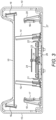
- Figure 3 shows a cross-sectional view of an embodiment of an antenna array assembly, the cross-section being in a plane perpendicular to the centre line of a linear array of patch radiator elements.
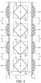
- Figure 4 shows a plan view of part of an embodiment, showing the first passive radiator 3 as a series of sections 13a - 13d and the second passive radiator 4 as a series of sections 14a - 14d.
- Figure 5 is an oblique view of part of an embodiment of the antenna array assembly
- Figure 6 is a plan view of part of an embodiment of the antenna array assembly.
- a ground plate 27, 26 is provided across the base of the sector antenna, that is to say the antenna array assembly, extending substantially across the width of the antenna array assembly.
- the ground plate acts as a radio frequency ground reference for the antenna, and may comprise more than one part connected together electrically.
- the patch radiator elements are orientated with each side of a square patch at substantially + or - 45 degrees to the centre line of the antenna array, shown in Figure 4 as a broken line.
- the patch radiator elements in conjunction with the ground plate, each forms a patch antenna that radiates and/or receives with linear orthogonal polarisations orientated at +/- 45 degrees to the centre line of the antenna array, as is well known in the art.
- the patch radiators may be configured to radiate in nominally vertical and horizontal polarisations, for example using square patches with two sides parallel to the centre line of the array.
- Patch radiator elements may be fed with signals using probes connected to a feed network running, for example, below the central section 26 of the ground plate, or the patch radiators may be edge fed for example, or fed by signals passing through a aperture, according to a wide variety of patch antenna implementation arrangements well-known in the art.
- the antenna array arrangement used as a sector antenna in a cellular system would be mounted on a tower at an access point, which may be an access point of a fixed wireless access system, for example proving data connections for residential and commercial premises in a geographical area.
- the sector antenna may be mounted with the centre line of the antenna array orientated approximately vertically, but may be provided with a slight down tilt either by the mechanical fixing arrangement of by the phasing of the signals fed to the patch radiator elements.
- the patch radiator elements may each have a first patch part 23, typically a planar conductive metallic square in a spaced parallel planar relationship with the ground plate 26, 27 and a second, similar but typically slightly smaller, patch part 24 situated in a planar parallel relationship with the first patch part, which may act as a director to shape the beam from the patch radiator element.
- the second patch part 24 may be separated from the first patch part 23 by a non-conducting spacer 25.
- first and second elongate passive radiators are provided, comprising sections 13 and 14 respectively which are shown truncated cross-section.
- the first and second elongate passive radiators 3, 4, corresponding to the elongate passive radiators 3 and 4 shown schematically in Figures 1 and 3 comprise a series of sections 13a - 13d and 14a - 14d respectively, each section being separated by a gap d of approximately a quarter wavelength at at least one operating frequency of the antenna array assembly.
- the width of each of the first and second elongate passive radiators 3, 4, measured in a direction pointing away from the ground plate 27, 26, is substantially 0.43 wavelengths at a centre frequency of operation.
- the width corresponds to w 3 in Figure 1 .
- the first and second elongate passive radiators 3, 4, and so also the sections of the first and second elongate passive radiators 13a - 13d and 14a - 14d respectively, are situated in this example approximately a half a wavelength from the centre of a patch antenna element, i.e. from the centre line of the array. This corresponds to distance d 3 in Figure 1 .
- the first and second passive radiators are inclined slightly towards each other, by up to 10degrees from perpendicular to the plane of the ground plate.
- the sections 13a-13c and 14a-14c which are typically metallic and electrically conductive, are attached to the ground plate by non-conductive support parts, which may be made from electrically insulating material such as plastic or a non-conductive composite material.
- non-conductive support parts which may be made from electrically insulating material such as plastic or a non-conductive composite material.
- the first and second elongate passive radiators may be attached to the radome instead of or in addition to being attached to the ground plate.
- third and fourth elongate passive radiators 15, 16, which are supported in this embodiment by brackets formed in the non-conductive radome 10, which covers the antenna array assembly and gives environmental protection and allows radiation to pass in and out of antenna array assembly, as an antenna beam typically with a centre approximately perpendicular to the ground plate.
- the azimuth direction is typically in the plane of the cross section of Figure 3 .
- the third and fourth elongate passive radiators 15, 16, which correspond to the third and fourth elongate passive radiators 5, 6 in the schematic views of Figures 1 and 2 are mage of flat metallic strips with the long dimension extending parallel to the centre line of the array, that is to say extending into and out of the paper in the cross-sectional view of Figure 3 .
- the width of each of the third and fourth elongate passive radiators 15, 16, measured in a direction pointing away from the ground plate 27, 26, is substantially a quarter of a wavelength at a centre frequency of operation. The width corresponds to w 2 in Figure 1 .
- the third and fourth elongate passive radiators 15, 16, are situated in this example approximately a wavelength from the centre of a patch antenna element, i.e. from the centre line of the array. This corresponds to distance d 2 in Figure 1 .
- the third and fourth elongate passive radiators are inclined towards each other slightly from perpendicular to the ground plate, by about 10-20 degrees, and are spaced by substantially half a wavelength from the ground plate. This corresponds to dimension h 2 in Figure 1 .
- fifth and sixth elongate passive radiators 17, 18, which are supported in this embodiment by non-conductive brackets 19, 20 which are mounted on the ground plate 27.
- the fifth and sixth elongate passive radiators 17, 18, which correspond to the fifth and sixth elongate passive radiators 7, 8 in the schematic views of Figures 1 and 2 are made of flat metallic strips with the long dimension extending parallel to the centre line of the array, that is to say extending into and out of the paper in the cross-sectional view of Figure 3 .
- the width of each of the fifth and sixth elongate passive radiators 17, 18, measured in a direction pointing away from the ground plate 27, 26, is substantially quarter of a wavelength at a centre frequency of operation.
- the width corresponds to w 1 in Figure 1 .
- the fifth and sixth elongate passive radiators 17, 18, are situated in this example between three quarters of a wavelength and a wavelength from the centre of a patch antenna element, i.e. from the centre line of the array. This corresponds to distance d 1 in Figure 1 .
- the fifth and sixth elongate passive radiators are substantially perpendicular to the ground plate, and spaced by less than a quarter wavelength from the ground plate. This corresponds to dimension hi in Figure 1 .
- the fifth and sixth elongate passive radiators may have a first substantially perpendicular section in relation to the ground plate and a second section connected to the first section which is inclined towards the array of radiator elements.
- An aspect of some embodiments relates to using combination of three flanges symmetrically on the both sides of the linear patch array.
- the first flange has a height that corresponds to half of the wavelength at the centre frequency and separated by approximately half wavelength from the centre of a patch. This may help to create a wide beam pattern at the centre, for example with nominally 90 degrees of beamwidth, by combining the main radiation form the patch array plus the secondary radiation from the flanges.
- the beamwidth to a roll off point of 1.4 dB from peak may be 80 degrees
- the beamwidth to a roll off point of 3 dB may be in the range 92 degrees.
- the 6 dB (+/- 2 dB) beamwidth may be 120 degrees, and the roll off from 60 degrees to 90 degrees may be -16 dB.
- the second set of two flanges may have a height equalling to quarter of the wavelength and separated by nearly one wavelength. These flanges are oriented at different heights and angles from the top patch. These two flanges help to create the required roll off in the pattern.
- the respective substantially planar conductive parts of the first and second elongate passive radiators 3, 4 may arranged in a respective zigzag arrangement in a cross-section taken in a plane parallel to the first face of the ground plane.
- the alternating planar conducting parts of each section 13a - 13d and 14a - 14d of the first and second elongate passive radiators 3, 4 are arranged as a zig zag.
- the combination of the zig-zag arrangement with the passive radiators may provide increased cross-polar isolation in combination with the broad beamwidth and fast roll-off.
- each section has three planar conducting parts at a first angle to the centre line of the linear array, and three planar conducting parts at a second angle to the centre line of the linear array, arranged alternately.
- the first angle is substantially -45 degrees and the second angle is substantially +45 degrees.
- the antenna array assembly may comprise a first and second elongate conductive wall 21, 22, connected electrically to the ground plate, each being disposed symmetrically on either side of the linear array and parallel to the centre line of the linear array, on the same side of the ground plate as the linear array, and closer to the linear array than are the first and second elongate passive radiators 3, 4.
- the first and second elongate conductive walls 21, 22 are substantially perpendicular to the first face of the ground plate, protruding from the ground plate by less than a quarter of a wavelength at at least one operating frequency of the antenna array assembly.
- the conductive walls may provide an improved beam shape in terms of a broad beamwidth and fast roll-off in combination with the other claimed features.
- Each patch radiator element is configured to radiate at orthogonal polarisations substantially +/- 45 degrees to the centre line of the linear array.
- the zig-zag shaped passive radiators may provide particularly good isolation between these orientations of polarisation.
- each of the third and fourth elongate passive radiators closest to the first face of the ground plate are substantially the same distance from the first face of the ground plate as are the edges of the first and second elongate passive radiators furthest from the first face of the first face of the ground plate. This may give an improved beam shape in terms of a broad beamwidth and fast roll-off in combination with the other claimed features.
- Each of the first and second elongate passive radiators 3, 4 may be composed of a series of sections, each comprising one or more substantially planar conductive parts, wherein a gap is provided between each section of 0.2 to 0.4 wavelengths, and for example a quarter of a wavelength, at at least one operating frequency of the antenna array assembly.
- the provision of gaps may provide increased isolation between the elements of the array while maintaining high cross-polar isolation and an improved beam shape.
- Each section has a length measured in a direction parallel to the centre line of the linear array in the range 0.4 to 0.6 wavelengths, and for example half a wavelength at at least one operating frequency of the antenna array assembly. This spacing of the gaps allows the sections to line up with a respective patch radiator element so that the gaps line up with the spaces between patch radiator elements.
- the ground plate and the elongate passive radiators may be composed of a solid metal such as aluminium, or may be composed of a non-conductive material having a conductive coating. This may allow the ground plate to be light weight and to be moulded in a shape to include the conductive walls, which may be an economical manufacturing method.
- the non-conductive moulding may comprise a plastic material and the conductive surface may comprise copper.
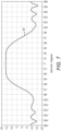
- Figure 7 shows a radiation plot 30 for the embodiment of the antenna array assembly illustrated in Figures 3 - 6 .
- the horizontal scale is in azimuth, which as has already been described is substantially in the plane of the cross-section of Figure 3 , with the peak of the beam radiating approximately in a perpendicular direction to the ground plate 27, 26.
- the vertical scale is in dBi. This illustrates that the main beam is flatter and broader than would be achieved by use of a conventional linear array of patch antenna elements for a sector antenna, and that the cut off outside the +/- 60 degree points is faster than for a conventional sector antenna..
- the -3dB beamwidth may be 80 degrees, as opposed to over 90 degrees in the present case, whereas the - 6dB beamwidth may be similar in both cases, indicating that embodiments of the invention have a faster roll-off than a conventional antenna. This reduces the angular sector of the coverage region in which a user may receive signals at similar levels from two adjacent sectors, so increasing capacity in a cellular system with a frequency re-use factor of 1.
- a patch radiator element disposed over a ground plate, forming a patch antenna is a type of radio antenna with a low profile, which can be mounted on a flat surface. It may consist of a flat rectangular sheet or "patch" of metal, mounted over a larger sheet of metal called a ground plane.
- the assembly may be contained inside a plastic radome, which protects the antenna structure from damage.
- the metal sheet above the ground plane may be viewed as forming a resonant piece of microstrip transmission line with a length of approximately one-half wavelength of the radio waves.
- the radiation mechanism may be viewed as arising from discontinuities at each truncated edge of the microstrip transmission line. The radiation at the edges may cause the antenna to act slightly larger electrically than its physical dimensions, so in order for the antenna to be resonant, a length of microstrip transmission line slightly shorter than one-half a wavelength at the frequency may used to form the patch.
Landscapes
- Engineering & Computer Science (AREA)
- Computer Networks & Wireless Communication (AREA)
- Waveguide Aerials (AREA)
- Variable-Direction Aerials And Aerial Arrays (AREA)
Description
- The present invention relates generally to an antenna array, and more specifically, but not exclusively, to an antenna array assembly for a cellular wireless sector antenna having improved beam shape with a broad main beam and faster roll-off.
- In modern wireless systems, such as, for example, cellular wireless access and fixed wireless access networks, there is a need for equipment, such as radio transceiver equipment in user equipment or at base stations or access points, which is economical to produce, while having high performance at radio frequencies. Increasingly high radio frequencies are being used as spectrum becomes scarce and demand for bandwidth increases. Furthermore, antenna systems are becoming increasingly sophisticated, often employing arrays of antenna elements to provide controlled beam shapes and/or MIMO (multiple input multiple output) transmission.
- It is known to implement a radio transceiver having an array of antenna radiator elements. A feed network may connect the antenna elements to transmit and receive chains of the transceiver. A ground plate may be provided, which may underlie the array of radiator elements, and which provides a radio frequency ground for the radiator elements.
- In some arrangements of a cellular wireless networks, in particular in LTE 4G networks, it may beneficial to operate with a frequency plan having a frequency re-use factor of 1, that is to say that adjacent sectors are operated using the same frequency band. In this case, signals transmitted in one sector may appear as interference to the adjacent sector. The coding and modulation schemes used for the transmission and reception of signals provide a tolerance of interference from other sectors, but there is typically some reduction in capacity at the boundaries between sectors. Ideally a sector antenna would have a flat, i.e. constant gain over the width of the sector in the main beam, and then a sharp cut off at angles outside the sector to minimise interference to an adjacent sector. A single linear array of patch antennas may conventionally be used as a sector antenna, for example covering a 120 degree sector, but the performance may be limited in terms of gain flatness within the sector and rate of cut-off outside the sector. It is possible to increase the width of a main beam and increase the rate of cut off by the use of a two-dimensional array of patch antennas, but such an array is physically large and complex.
- United States patent application
US 2007/0146225 A1 relates to a dual polarised antenna with at least one dual polarised radiator device provided with longitudinal or transverse webs. - International patent application
WO 98/36472 A1 - United States patent application
US 2006/0139231 A1 relates to An antenna comprising a rectangular reflector; first and second dipole antennae disposed in front of the reflector and aligned parallel to the long edge of the reflector; rod-shaped first metal conductors arranged parallel to the first and second dipole antennae. - It is an object of the invention to mitigate the problems of the prior art.
- In accordance with a first aspect of the present invention, there is provided an antenna array assembly, comprising:
- a ground plate;
- a linear array of patch radiator elements disposed in a spaced parallel relationship with a first face of the ground plate; and
- a first and second elongate passive radiator each comprising one or more substantially planar conductive parts disposed to be upstanding in relation to the first face of the ground plate and being electrically isolated from the ground plate, the first and second elongate passive radiators being disposed symmetrically on either side of the linear array and parallel to a centre line of the linear array, on the same side of the ground plate as the linear array;
- a third and fourth elongate passive radiator each comprising one or more substantially planar conductive parts disposed to be upstanding in relation to the first face of the ground plate, and being electrically isolated from the ground plate, the third and fourth elongate passive radiators being disposed symmetrically on either side of the linear array and parallel to the centre line of the linear array, on the same side of the ground plate as the linear array, and further from the linear array than are the first and second elongate passive radiators,
- wherein a width of each of the first and second elongate passive radiators measured in a direction pointing away from the first face of the ground plate is greater than a width of each of the third and fourth elongate passive radiators measured in a direction pointing away from the first face of the ground plate, and
- wherein each of the each of the third and fourth elongate passive radiators is spaced from the first face of the ground plate by a first distance such that each of the third and fourth elongate passive radiators projects further from the ground plate than does each of the first and second elongate passive radiators.
- The combination of the third and fourth passive radiators outside the first and second radiators, and with a width less than that of the first and second radiators, but protruding further from the ground plate than the first and second radiators, has been found to provide a broad main beam with a fast roll-off. The first and second radiators may broaden the beam, while the third and fourth passive radiators disposed as specified may give a faster cut off, counteracting the effect of the first and second radiators outside the main beam.
- In an embodiment of the invention, the width of each of the first and second elongate passive radiators is in the range 0.4 to 0.6 wavelengths, and in an example substantially half a wavelength, at at least one operating frequency of the antenna array assembly and the width of each of the third and fourth elongate passive radiators is in the range 0.2 to 0.4 wavelengths, and in an example substantially a quarter wavelength at at least one operating frequency of the antenna array assembly.
- Antenna array assemblies with passive radiators having the specified widths may give particularly good performance.
- In an embodiment of the invention, each of the first and second elongate passive radiators is disposed 0.4 to 0.6 wavelengths, and in an example substantially half a wavelength, away from the centre line of the linear array of patch radiator elements at at least one operating frequency of the antenna array assembly and each of the third and fourth elongate passive radiators is disposed 0.8 to 1.2 wavelengths, and in an example one wavelength away from the centre line of the linear array of patch radiator elements at a operating frequency of the antenna array assembly. Antenna array assemblies with passive radiators situated in this way may give particularly good performance.
- In an embodiment of the invention, the antenna array assembly comprises a fifth and sixth elongate passive radiator each comprising one or more substantially planar conductive parts disposed to be generally upstanding in relation to the first face of the ground plate and being electrically isolated from the ground plate, the fifth and sixth elongate passive radiators being disposed symmetrically on either side of the linear array and parallel to the centre line of the linear array, on the same side of the ground plate as the linear array, and further from the linear array than are the first and second elongate passive radiators,
wherein each of the each of the fifth and sixth elongate passive radiators is spaced from the first face of the ground plate by a second distance such that each of the first and second elongate passive radiators projects further from the ground plate than does each of the fifth and sixth elongate passive radiators. - The provision of the fifth and sixth elongate passive radiators may improve the roll-off of the antenna response in azimuth outside the main beam in combination with the third and fourth passive radiators.
- In an embodiment of the invention, each of the fifth and sixth elongate passive radiators has a width in the range 0.2 to 0.4 wavelengths, and in an example substantially a quarter of a wavelength, at at least one operating frequency of the antenna array assembly.
- In an embodiment of the invention, at least some of the respective substantially planar conductive parts of the first and second elongate passive radiators are arranged in a respective zigzag arrangement in a cross-section taken in a plane parallel to the first face of the ground plane.
- The combination of the zig-zag arrangement with the passive radiators may provide increased cross-polar isolation in combination with the broad beamwidth and fast roll-off.
- In an embodiment of the invention, each of the first and second elongate passive radiators is inclined towards the linear array of patch radiator elements by an angle of less than 10 degrees from perpendicular to the first face of the ground plate.
- This may give an improved beam shape in terms of a broad beamwidth and fast roll-off in combination with the other claimed features.
- In an embodiment of the invention, each of the third and fourth elongate passive radiators is inclined towards the linear array of patch radiator elements by an angle of less than 10 degrees to from perpendicular to the first face of the ground plate.
- This may give an improved beam shape in terms of a broad beamwidth and fast roll-off in combination with the other claimed features.
- In an embodiment of the invention, the antenna array assembly comprises a first and second elongate conductive wall each being disposed symmetrically on either side of the linear array and parallel to the centre line of the linear array, on the same side of the ground plate as the linear array, and closer to the linear array than are the first and second elongate passive radiators, wherein the first and second elongate conductive walls are electrically connected to the first face of the ground plate and are substantially perpendicular to the first face of the ground plate, protruding from the ground plate by less than a quarter of a wavelength at at least one operating frequency of the antenna array assembly.
- The conductive walls may provide an improved beam shape in terms of a broad beamwidth and fast roll-off in combination with the other claimed features.
- In an embodiment of the invention, the ground plate comprises a base plate to which the first and second elongate passive radiators are mounted and a raised section disposed between the base plate and the patch radiator elements comprising at least part of the first face of the ground plate.
- This may provide a convenient mounting method for the linear array.
- In an embodiment of the invention, each patch radiator element comprises a first planar part disposed in a spaced parallel relationship to the first face of the ground plate and a second planar part disposed in a spaced parallel relationship to the first planar part, on the side of the first planar part away from the first face of the ground plate.
- This may give an improved beam shape in terms of a broad beamwidth and fast roll-off in combination with the other claimed features.
- In an embodiment of the invention, each patch radiator element is configured to radiate at orthogonal polarisations substantially +/- 45 degrees to the centre line of the linear array.
- The zig-zag shaped passive radiators may provide particularly good isolation between these orientations of polarisation.
- In an embodiment of the invention, the third and fourth elongate passive radiators are attached to a radome covering the antenna array assembly.
- This may provide a convenient method of suspending the passive radiators above the ground plate.
- In an embodiment of the invention, the edge of each of the third and fourth elongate passive radiators closest to the first face of the ground plate are substantially the same distance from the first face of the ground plate as are the edges of the first and second elongate passive radiators furthest from the first face of the first face of the ground plate.
- This may give an improved beam shape in terms of a broad beamwidth and fast roll-off in combination with the other claimed features.
- In an embodiment of the invention, each of the first and second elongate passive radiators is composed of a series of sections, each comprising one or more substantially planar conductive parts, wherein a gap is provided between each section of 0.2 to 0.4 wavelengths, and for example a quarter of a wavelength, at at least one operating frequency of the antenna array assembly.
- The provision of gaps may provide increased isolation between the elements of the array while maintaining high cross-polar isolation and an improved beam shape.
- In an embodiment of the invention, each section has a length measured in a direction parallel to the centre line of the linear array in the range 0.4 to 0.6 wavelengths, and for example half a wavelength at at least one operating frequency of the antenna array assembly.
- This spacing of the gaps allows the sections to line up with a respective patch radiator element so that the gaps line up with the spaces between patch radiator elements.
- This may provide increased isolation between the elements of the array while maintaining high cross-polar isolation and an improved beam shape.
- Further features and advantages of the invention will be apparent from the following description of preferred embodiments of the invention, which are given by way of example only.
-
-
Figure 1 shows a schematic representation of an antenna array assembly in cross-section; -
Figure 2 shows a schematic representation of the antenna array assembly ofFigure 1 with a viewing angle perpendicular to the ground plate view; -
Figure 3 shows a truncated oblique cross-sectional view of an embodiment of an antenna array assembly; -
Figure 4 shows a part of an embodiment of the antenna array assembly with a viewing angle perpendicular to the ground plate; -
Figure 5 is an oblique view of part of an embodiment of the antenna array assembly; -
Figure 6 is a view of part of an embodiment of the antenna array assembly with a viewing angle perpendicular to the ground plate; and -
Figure 7 shows a gain response of an embodiment of an antenna array assembly in azimuth - By way of example, embodiments of the invention will now be described in the context of an antenna array assembly having a ground plate which is a backing plate for an array of printed antenna elements for use as a sector antenna for an access point of a fixed wireless access system operating according to a 4G LTE coding, modulation and signalling scheme. However, it will be understood that this is by way of example only and that other embodiments may be antenna array assemblies in other wireless systems, including mobile wireless systems operating according to 3GPP 4G LTE standards, and according to 5G or other standards, operating in a variety of signal transmission bands. In an embodiment of the invention, an operating frequency range of approximately 2.3 to 2.7 GHz, with a centre frequency of 2.5 GHz is used, but the embodiments of the invention are not restricted to this frequency, and in particular embodiments of the invention are suitable for use at lower or higher operating frequencies of up to 20 GHz or even higher.
-
Figures 1 and2 are schematic diagrams of an antenna array assembly in an embodiment of the invention. As shown, a linear array ofpatch radiator elements - As may be seen from
Figure 1 in cross-sectional view andFigure 2 in plan view, the antenna array assembly is provided with first and second elongatepassive radiators passive radiators passive radiators - As shown in
Figure 1 , the first and second elongatepassive radiators passive radiators - As shown in
Figures 1 and2 , the antenna array assembly is provided with another pair of elongatepassive radiators Figure 1 , typically w3 > w2, and h5 > h6. - As shown in the example of
Figure 1 , the second pair of elongatepassive radiators passive radiator 5, and the fourth elongatepassive radiator 6, may each be substantially perpendicular to the first face of the ground plate 1. In alternative arrangements, the third and fourth elongate passive radiators are disposed to be generally upstanding in relation to the first face of the ground plate and may be inclined by an angle of up to about 15 degrees from the vertical, i.e. from the perpendicular, that is to say disposed at an angle of at least 75 degrees to the first face of the ground plate. In ab example of an arrangement the third and fourth elongate passive radiators may each tilt inwards towards the array of patch radiator elements at an angle of up to about 10 degrees from perpendicular. The third and fourth elongatepassive radiators passive radiators - So, the substantially planar conductive parts are disposed to be generally upstanding in relation to the first face of the ground plate and electrically isolated from the ground plate, the third and fourth elongate passive radiators being disposed symmetrically on either side of the linear array and parallel to the centre line of the linear array, on the same side of the ground plate as the linear array, and further from the linear array than are the first and second elongate passive radiators. The centre line of the linear array of patch radiator elements may be referred to as a long axis of the array. The long axis typically runs through the centres of the patch radiator elements, as shown in
Figure 2 by the broken line. - As has already been mentioned, the inner pair of radiators is narrower than the outer pair, that is to say a width of each of the first and second elongate
passive radiators passive radiators passive radiators passive radiators passive radiators - The combination of third and fourth
passive radiators passive radiators second radiators passive radiators - Particularly good performance may be achieved in some embodiments when the width w3 of each of the first and second elongate
passive radiators passive radiators - Also, particularly good performance may be achieved in some embodiments when each of the first and second elongate
passive radiators - Further improvements to the roll-off of the antenna response in azimuth outside the main beam may be achieved in some embodiments by the provision of a fifth and sixth elongate
passive radiator Figures 1 and2 , which may have a similar composition and width to the third and fourth elongatepassive radiators passive radiators Figure 1 . As shown inFigures 1 and2 , each of the fifth and sixth elongatepassive radiators passive radiators Figures 1 and2 , each of the fifth and sixth elongatepassive radiators passive radiators passive radiators passive radiators passive radiators passive radiators - In an embodiment of the invention, each of the fifth and sixth elongate passive radiators has a width in the range 0.2 to 0.4 wavelengths, and in an example substantially a quarter of a wavelength, at at least one operating frequency of the antenna array assembly.
-
Figures 3-6 show an antenna array assembly in an embodiment of the invention., which may be used as a sector antenna for an access point for operation in a cellular system having approximately 120 degree sectors.Figure 3 shows a cross-sectional view of an embodiment of an antenna array assembly, the cross-section being in a plane perpendicular to the centre line of a linear array of patch radiator elements.Figure 4 shows a plan view of part of an embodiment, showing the firstpassive radiator 3 as a series ofsections 13a - 13d and the secondpassive radiator 4 as a series ofsections 14a - 14d.Figure 5 is an oblique view of part of an embodiment of the antenna array assembly, andFigure 6 is a plan view of part of an embodiment of the antenna array assembly. - It may be seen from
Figures 3-6 that aground plate central section 26, which acts as a support for the antenna elements, which arepatch radiator elements Figure 3 and 23a-d and 24a-d as shown in at least some ofFigures 4 ,5 and6 . As shown, the patch radiator elements are orientated with each side of a square patch at substantially + or - 45 degrees to the centre line of the antenna array, shown inFigure 4 as a broken line. This is so that the patch radiator elements, in conjunction with the ground plate, each forms a patch antenna that radiates and/or receives with linear orthogonal polarisations orientated at +/- 45 degrees to the centre line of the antenna array, as is well known in the art. In alternative embodiments, the patch radiators may be configured to radiate in nominally vertical and horizontal polarisations, for example using square patches with two sides parallel to the centre line of the array. Patch radiator elements may be fed with signals using probes connected to a feed network running, for example, below thecentral section 26 of the ground plate, or the patch radiators may be edge fed for example, or fed by signals passing through a aperture, according to a wide variety of patch antenna implementation arrangements well-known in the art. Typically, the antenna array arrangement used as a sector antenna in a cellular system would be mounted on a tower at an access point, which may be an access point of a fixed wireless access system, for example proving data connections for residential and commercial premises in a geographical area. The sector antenna may be mounted with the centre line of the antenna array orientated approximately vertically, but may be provided with a slight down tilt either by the mechanical fixing arrangement of by the phasing of the signals fed to the patch radiator elements. The patch radiator elements may each have afirst patch part 23, typically a planar conductive metallic square in a spaced parallel planar relationship with theground plate part 24 situated in a planar parallel relationship with the first patch part, which may act as a director to shape the beam from the patch radiator element. Thesecond patch part 24 may be separated from thefirst patch part 23 by anon-conducting spacer 25. - As shown in
Figure 3 in a truncated oblique cross-sectional view, first and second elongate passive radiators are provided, comprisingsections Figure 4 , the first and second elongatepassive radiators passive radiators Figures 1 and3 , comprise a series ofsections 13a - 13d and 14a - 14d respectively, each section being separated by a gap d of approximately a quarter wavelength at at least one operating frequency of the antenna array assembly. In the example shown, the width of each of the first and second elongatepassive radiators ground plate Figure 1 . The first and second elongatepassive radiators passive radiators 13a - 13d and 14a - 14d respectively, are situated in this example approximately a half a wavelength from the centre of a patch antenna element, i.e. from the centre line of the array. This corresponds to distance d3 inFigure 1 . In the embodiment shown, the first and second passive radiators are inclined slightly towards each other, by up to 10degrees from perpendicular to the plane of the ground plate. As shown in particular inFigure 3 andFigure 5 , thesections 13a-13c and 14a-14c which are typically metallic and electrically conductive, are attached to the ground plate by non-conductive support parts, which may be made from electrically insulating material such as plastic or a non-conductive composite material. As shown inFigures 5 and6 , there are supportingnon-conductive spacers passive radiators - As also shown in
Figure 3 , there are provided third and fourth elongatepassive radiators non-conductive radome 10, which covers the antenna array assembly and gives environmental protection and allows radiation to pass in and out of antenna array assembly, as an antenna beam typically with a centre approximately perpendicular to the ground plate. For a sector antenna mounted with the centre line of the array approximately vertical, the azimuth direction is typically in the plane of the cross section ofFigure 3 . In this example, the third and fourth elongatepassive radiators passive radiators Figures 1 and2 , are mage of flat metallic strips with the long dimension extending parallel to the centre line of the array, that is to say extending into and out of the paper in the cross-sectional view ofFigure 3 . In the example shown, the width of each of the third and fourth elongatepassive radiators ground plate Figure 1 . The third and fourth elongatepassive radiators Figure 1 . In this example, the third and fourth elongate passive radiators are inclined towards each other slightly from perpendicular to the ground plate, by about 10-20 degrees, and are spaced by substantially half a wavelength from the ground plate. This corresponds to dimension h2 inFigure 1 . - As also shown in
Figure 3 , there are provided fifth and sixth elongatepassive radiators non-conductive brackets ground plate 27. In this example, the fifth and sixth elongatepassive radiators passive radiators Figures 1 and2 , are made of flat metallic strips with the long dimension extending parallel to the centre line of the array, that is to say extending into and out of the paper in the cross-sectional view ofFigure 3 . In the example shown, the width of each of the fifth and sixth elongatepassive radiators ground plate Figure 1 . The fifth and sixth elongatepassive radiators Figure 1 . In this example, the fifth and sixth elongate passive radiators are substantially perpendicular to the ground plate, and spaced by less than a quarter wavelength from the ground plate. This corresponds to dimension hi inFigure 1 . The fifth and sixth elongate passive radiators may have a first substantially perpendicular section in relation to the ground plate and a second section connected to the first section which is inclined towards the array of radiator elements. - An aspect of some embodiments relates to using combination of three flanges symmetrically on the both sides of the linear patch array. The first flange has a height that corresponds to half of the wavelength at the centre frequency and separated by approximately half wavelength from the centre of a patch. This may help to create a wide beam pattern at the centre, for example with nominally 90 degrees of beamwidth, by combining the main radiation form the patch array plus the secondary radiation from the flanges. In an example, the beamwidth to a roll off point of 1.4 dB from peak may be 80 degrees, and the beamwidth to a roll off point of 3 dB may be in the range 92 degrees. The 6 dB (+/- 2 dB) beamwidth may be 120 degrees, and the roll off from 60 degrees to 90 degrees may be -16 dB. The second set of two flanges may have a height equalling to quarter of the wavelength and separated by nearly one wavelength. These flanges are oriented at different heights and angles from the top patch. These two flanges help to create the required roll off in the pattern.
- As may be seen from
Figure 4 , at least some of the respective substantially planar conductive parts of the first and second elongatepassive radiators section 13a - 13d and 14a - 14d of the first and second elongatepassive radiators - As may be seen from
Figures 3 ,4 and5 , in an embodiment of the invention, the antenna array assembly may comprise a first and second elongateconductive wall passive radiators conductive walls - Each patch radiator element is configured to radiate at orthogonal polarisations substantially +/- 45 degrees to the centre line of the linear array. The zig-zag shaped passive radiators may provide particularly good isolation between these orientations of polarisation.
- In an embodiment of the invention, the edge of each of the third and fourth elongate passive radiators closest to the first face of the ground plate are substantially the same distance from the first face of the ground plate as are the edges of the first and second elongate passive radiators furthest from the first face of the first face of the ground plate. This may give an improved beam shape in terms of a broad beamwidth and fast roll-off in combination with the other claimed features.
- Each of the first and second elongate
passive radiators - The ground plate and the elongate passive radiators may be composed of a solid metal such as aluminium, or may be composed of a non-conductive material having a conductive coating. This may allow the ground plate to be light weight and to be moulded in a shape to include the conductive walls, which may be an economical manufacturing method. The non-conductive moulding may comprise a plastic material and the conductive surface may comprise copper.
-
Figure 7 shows aradiation plot 30 for the embodiment of the antenna array assembly illustrated inFigures 3 - 6 . The horizontal scale is in azimuth, which as has already been described is substantially in the plane of the cross-section ofFigure 3 , with the peak of the beam radiating approximately in a perpendicular direction to theground plate - As is well known in the art, a patch radiator element disposed over a ground plate, forming a patch antenna, is a type of radio antenna with a low profile, which can be mounted on a flat surface. It may consist of a flat rectangular sheet or "patch" of metal, mounted over a larger sheet of metal called a ground plane. The assembly may be contained inside a plastic radome, which protects the antenna structure from damage. The metal sheet above the ground plane may be viewed as forming a resonant piece of microstrip transmission line with a length of approximately one-half wavelength of the radio waves. The radiation mechanism may be viewed as arising from discontinuities at each truncated edge of the microstrip transmission line. The radiation at the edges may cause the antenna to act slightly larger electrically than its physical dimensions, so in order for the antenna to be resonant, a length of microstrip transmission line slightly shorter than one-half a wavelength at the frequency may used to form the patch.
- The above embodiments are to be understood as illustrative examples of the invention. Furthermore, modifications not described above may also be employed without departing from the scope of the invention, which is defined in the accompanying claims.
Claims (15)
- An antenna array assembly, comprising:a ground plate (1);a linear array of patch radiator elements (2, 2a-2c) disposed in a spaced parallel relationship with a first face of the ground plate; anda first and second elongate passive radiator (3, 4) each comprising one or more substantially planar conductive parts disposed to be upstanding in relation to the first face of the ground plate (1) and being electrically isolated from the ground plate (1), the first and second elongate passive radiators (3, 4) being disposed symmetrically on either side of the linear array and parallel to a centre line of the linear array, on the same side of the ground plate (1) as the linear array;a third and fourth elongate passive radiator (5, 6) each comprising one or more substantially planar conductive parts disposed to be upstanding in relation to the first face of the ground plate (1) and being electrically isolated from the ground plate (1), the third and fourth elongate passive radiators (5, 6) being disposed symmetrically on either side of the linear array and parallel to the centre line of the linear array, on the same side of the ground plate (1) as the linear array, and further from the linear array than the first and second elongate passive radiators (3, 4),wherein a width of each of the first and second elongate passive radiators (3, 4) measured in a direction pointing away from the first face of the ground plate (1) is greater than a width of each of the third and fourth elongate passive radiators (5, 6) measured in a direction pointing away from the first face of the ground plate (1), andcharacterized in that each of the each of the third and fourth elongate passive radiators (5, 6) is spaced from the first face of the ground plate (1) by a first distance such that each of the third and fourth elongate passive radiators (5, 6) projects further from the ground plate (1) than each of the first and second elongate passive radiators (3, 4).
- An antenna array assembly according to claim 1, wherein the width of each of the first and second elongate passive radiators (3, 4) is in the range 0.4 to 0.6 wavelengths at an operating frequency of the antenna array assembly and the width of each of the third and fourth elongate passive radiators (5, 6) is in the range 0.2 to 0.4 wavelengths at an operating frequency of the antenna array assembly.
- An antenna array assembly according to claim 1, wherein the width of each of the first and second elongate passive radiators (3, 4) is substantially half a wavelength at an operating frequency of the antenna array assembly and the width of each of the third and fourth elongate passive radiators (5, 6) is substantially a quarter wavelength at an operating frequency of the antenna array assembly.
- An antenna array assembly according to any preceding claim, each of the first and second elongate passive radiators (3, 4) is disposed 0.4 to 0.6 wavelengths away from the centre line of the linear array of patch radiator elements at an operating frequency of the antenna array assembly and each of the third and fourth elongate passive radiators (5, 6) is disposed 0.8 to 1.2 wavelengths away from the centre line of the linear array of patch radiator elements at an operating frequency of the antenna array assembly.
- An antenna array assembly according to any preceding claim, each of the first and second elongate passive radiators (3, 4) is disposed substantially half a wavelength away from the centre line of the linear array of patch radiator elements at an operating frequency of the antenna array assembly and each of the third and fourth elongate passive radiators (5, 6) is disposed substantially one wavelength away from the centre line of the linear array of patch radiator elements.
- An antenna array assembly according to any preceding claim comprising a fifth and sixth elongate passive radiator (7, 8) each comprising one or more substantially planar conductive parts disposed to be upstanding in relation to the first face of the ground plate (1) and being electrically isolated from the ground plate (1), the fifth and sixth elongate passive radiators (7, 8) being disposed symmetrically on either side of the linear array and parallel to the centre line of the linear array, on the same side of the ground plate as the linear array, and further from the linear array than are the first and second elongate passive radiators (3, 4),
wherein each of the each of the fifth and sixth elongate passive radiators (7, 8) is spaced from the first face of the ground plate (1) by a second distance such that each of the first and second elongate passive radiators (3, 4) projects further from the ground plate (1) than does each of the fifth and sixth elongate passive radiators (7, 8), wherein each of the fifth and sixth elongate passive radiators (7, 8) has a width in the range 0.2 to 0.4 wavelengths at an operating frequency of the antenna array assembly. - An antenna array assembly according to any preceding claim, wherein at least some of the respective substantially planar conductive parts of the first and second elongate passive radiators (3, 4) are arranged in a respective zigzag arrangement in a cross-section taken in a plane parallel to the first face of the ground plate (1),
- An antenna array assembly according to claim 7, wherein each of the first, second, third and fourth elongate passive radiators (3, 4, 5, 6) is inclined towards the linear array of patch radiator elements by an angle of less than 10 degrees from perpendicular to the first face of the ground plate (1).
- An antenna array assembly according to any preceding claim, comprising a first and second elongate conductive wall (21, 22) each being disposed symmetrically on either side of the linear array and parallel to the centre line of the linear array, on the same side of the ground plate (1) as the linear array, and closer to the linear array than are the first and second elongate passive radiators (3, 4), wherein the first and second elongate conductive walls (21, 22) are electrically connected to the first face of the ground plate (1) and are substantially perpendicular to the first face of the ground plate (1), protruding from the ground plate by less than a quarter of a wavelength at an operating frequency of the antenna array assembly.
- An antenna array assembly according to any preceding claim, wherein the ground plate (1) comprises a base plate to which the first and second elongate passive radiators are mounted and a raised section disposed between the base plate and the patch radiator elements comprising at least part of the first face of the ground plate.
- An antenna array assembly according to any preceding claim, wherein each patch radiator element comprises a first planar part (23) disposed in a spaced parallel relationship to the first face of the ground plate and a second planar part (24) disposed in a spaced parallel relationship to the first planar part, on the side of the first planar part away from the first face of the ground plate.
- An antenna array assembly according to any preceding claim, wherein each patch radiator element (2, 2a-2c, 23, 24) is configured to radiate at orthogonal polarisations substantially +/- 45 degrees to the centre line of the linear array.
- An antenna array assembly according to any preceding claim, wherein the edges of each of the third and fourth elongate passive radiators (5, 6) closest to the first face of the ground plate are substantially the same distance from the first face of the ground plate as are the edges of the first and second elongate passive radiators (3, 4) furthest from the first face of the first face of the ground plate.
- An antenna array assembly according to any preceding claims, wherein each of the first and second elongate passive radiators (3, 4) is composed of a series of sections (14a - 14d), each comprising one or more substantially planar conductive parts, wherein a gap is provided between each section of 0.2 to 0.4 wavelengths at an operating frequency of the antenna array assembly.
- An antenna array assembly according to claim 14, wherein each section (14a-14d) has a length measured in a direction parallel to the centre line of the linear array in the range 0.4 to 0.6 wavelengths at an operating frequency of the antenna array assembly.
Applications Claiming Priority (2)
| Application Number | Priority Date | Filing Date | Title |
|---|---|---|---|
| IN201941020526 | 2019-05-23 | ||
| PCT/GB2020/051231 WO2020234590A1 (en) | 2019-05-23 | 2020-05-20 | Antenna array assembly |
Publications (2)
| Publication Number | Publication Date |
|---|---|
| EP3973592A1 EP3973592A1 (en) | 2022-03-30 |
| EP3973592B1 true EP3973592B1 (en) | 2023-09-06 |
Family
ID=71130993
Family Applications (1)
| Application Number | Title | Priority Date | Filing Date |
|---|---|---|---|
| EP20734437.5A Active EP3973592B1 (en) | 2019-05-23 | 2020-05-20 | Antenna array assembly |
Country Status (3)
| Country | Link |
|---|---|
| US (1) | US11936113B2 (en) |
| EP (1) | EP3973592B1 (en) |
| WO (1) | WO2020234590A1 (en) |
Families Citing this family (4)
| Publication number | Priority date | Publication date | Assignee | Title |
|---|---|---|---|---|
| EP3973592B1 (en) | 2019-05-23 | 2023-09-06 | Cambium Networks Ltd | Antenna array assembly |
| WO2022141131A1 (en) * | 2020-12-29 | 2022-07-07 | 华为技术有限公司 | Antenna and base station |
| KR102952337B1 (en) * | 2021-04-02 | 2026-04-14 | 삼성전자주식회사 | Antenna radome and electronic device including the same |
| WO2026017246A1 (en) * | 2024-07-16 | 2026-01-22 | Huawei Technologies Co., Ltd. | Antenna system |
Citations (5)
| Publication number | Priority date | Publication date | Assignee | Title |
|---|---|---|---|---|
| DE102005061636A1 (en) * | 2005-12-22 | 2007-06-28 | Kathrein-Werke Kg | Antenna for base station of mobile radio antenna, has longitudinal and/or cross bars that are length-variable in direct or indirect manner by deviation and/or bending and/or deformation and curving |
| JP2012054653A (en) * | 2010-08-31 | 2012-03-15 | Nippon Dengyo Kosaku Co Ltd | Antenna device and array antenna |
| JP2012142879A (en) * | 2011-01-06 | 2012-07-26 | Hitachi Cable Ltd | Sector antenna |
| US20140168027A1 (en) * | 2012-12-14 | 2014-06-19 | Raja Reddy KATIPALLY | Broadband In-Line Antenna Systems And Related Methods |
| WO2018209577A1 (en) * | 2017-05-16 | 2018-11-22 | 华为技术有限公司 | Antenna |
Family Cites Families (7)
| Publication number | Priority date | Publication date | Assignee | Title |
|---|---|---|---|---|
| SE508537C2 (en) * | 1997-02-14 | 1998-10-12 | Ericsson Telefon Ab L M | Double-polarized antenna for receiving and transmitting electromagnetic signals |
| US6462710B1 (en) * | 2001-02-16 | 2002-10-08 | Ems Technologies, Inc. | Method and system for producing dual polarization states with controlled RF beamwidths |
| JP3884042B2 (en) * | 2004-12-27 | 2007-02-21 | 株式会社エヌ・ティ・ティ・ドコモ | Antenna using four metal conductors |
| US7427966B2 (en) * | 2005-12-28 | 2008-09-23 | Kathrein-Werke Kg | Dual polarized antenna |
| RU2012154791A (en) * | 2012-08-09 | 2014-10-27 | Дмитрий Витальевич Татарников | ANTENNA SYSTEM (OPTIONS) |
| GB2548422B (en) | 2016-03-17 | 2019-06-05 | Cambium Networks Ltd | Antenna array assembly with conductive sidewalls for improved directivity |
| EP3973592B1 (en) | 2019-05-23 | 2023-09-06 | Cambium Networks Ltd | Antenna array assembly |
-
2020
- 2020-05-20 EP EP20734437.5A patent/EP3973592B1/en active Active
- 2020-05-20 WO PCT/GB2020/051231 patent/WO2020234590A1/en not_active Ceased
-
2021
- 2021-11-23 US US17/534,045 patent/US11936113B2/en active Active
Patent Citations (6)
| Publication number | Priority date | Publication date | Assignee | Title |
|---|---|---|---|---|
| DE102005061636A1 (en) * | 2005-12-22 | 2007-06-28 | Kathrein-Werke Kg | Antenna for base station of mobile radio antenna, has longitudinal and/or cross bars that are length-variable in direct or indirect manner by deviation and/or bending and/or deformation and curving |
| CN101160692B (en) * | 2005-12-22 | 2013-01-02 | 凯瑟雷恩工厂两合公司 | Dual polarized antennas with vertical or transverse strips |
| JP2012054653A (en) * | 2010-08-31 | 2012-03-15 | Nippon Dengyo Kosaku Co Ltd | Antenna device and array antenna |
| JP2012142879A (en) * | 2011-01-06 | 2012-07-26 | Hitachi Cable Ltd | Sector antenna |
| US20140168027A1 (en) * | 2012-12-14 | 2014-06-19 | Raja Reddy KATIPALLY | Broadband In-Line Antenna Systems And Related Methods |
| WO2018209577A1 (en) * | 2017-05-16 | 2018-11-22 | 华为技术有限公司 | Antenna |
Also Published As
| Publication number | Publication date |
|---|---|
| WO2020234590A1 (en) | 2020-11-26 |
| US11936113B2 (en) | 2024-03-19 |
| US20220085518A1 (en) | 2022-03-17 |
| EP3973592A1 (en) | 2022-03-30 |
Similar Documents
| Publication | Publication Date | Title |
|---|---|---|
| US12160038B2 (en) | Antenna array assembly having high cross polar isolation | |
| US11936113B2 (en) | Antenna array assembly | |
| CN110612639B (en) | Base station antenna with parasitic coupling elements | |
| US7196674B2 (en) | Dual polarized three-sector base station antenna with variable beam tilt | |
| US8487816B2 (en) | Patch antenna element array | |
| CN1214488C (en) | Dual band antenna | |
| EP3427336B1 (en) | Antenna array assembly | |
| EP3311449B1 (en) | Efficient planar phased array antenna assembly | |
| US7868842B2 (en) | Base station antenna with beam shaping structures | |
| RU2576592C2 (en) | Broadband microstrip antennae and antenna arrays | |
| EP2477275A1 (en) | Patch antenna | |
| US10658743B2 (en) | Antenna array assembly | |
| KR102601186B1 (en) | Multi-band Multi-array Base Station Antenna | |
| US20220285857A1 (en) | Base station antennas having low cost wideband cross-dipole radiating elements | |
| US12362462B2 (en) | Base station antennas having parasitic elements on multiple faces of a reflector | |
| WO1998036472A1 (en) | Dual-polarized antenna | |
| US20090160729A1 (en) | Antenna array with reduced electromagnetic coupling | |
| EP0805515A2 (en) | Antenna cross-polar suppression means | |
| CN211376942U (en) | Grid type waveguide antenna array of mobile communication base station | |
| CN112636003A (en) | Array antenna and mounting plate device thereof | |
| US11145968B2 (en) | Array antenna and sector antenna |
Legal Events
| Date | Code | Title | Description |
|---|---|---|---|
| STAA | Information on the status of an ep patent application or granted ep patent |
Free format text: STATUS: UNKNOWN |
|
| STAA | Information on the status of an ep patent application or granted ep patent |
Free format text: STATUS: THE INTERNATIONAL PUBLICATION HAS BEEN MADE |
|
| PUAI | Public reference made under article 153(3) epc to a published international application that has entered the european phase |
Free format text: ORIGINAL CODE: 0009012 |
|
| STAA | Information on the status of an ep patent application or granted ep patent |
Free format text: STATUS: REQUEST FOR EXAMINATION WAS MADE |
|
| 17P | Request for examination filed |
Effective date: 20211223 |
|
| AK | Designated contracting states |
Kind code of ref document: A1 Designated state(s): AL AT BE BG CH CY CZ DE DK EE ES FI FR GB GR HR HU IE IS IT LI LT LU LV MC MK MT NL NO PL PT RO RS SE SI SK SM TR |
|
| DAV | Request for validation of the european patent (deleted) | ||
| DAX | Request for extension of the european patent (deleted) | ||
| GRAP | Despatch of communication of intention to grant a patent |
Free format text: ORIGINAL CODE: EPIDOSNIGR1 |
|
| STAA | Information on the status of an ep patent application or granted ep patent |
Free format text: STATUS: GRANT OF PATENT IS INTENDED |
|
| INTG | Intention to grant announced |
Effective date: 20230320 |
|
| GRAS | Grant fee paid |
Free format text: ORIGINAL CODE: EPIDOSNIGR3 |
|
| GRAA | (expected) grant |
Free format text: ORIGINAL CODE: 0009210 |
|
| STAA | Information on the status of an ep patent application or granted ep patent |
Free format text: STATUS: THE PATENT HAS BEEN GRANTED |
|
| AK | Designated contracting states |
Kind code of ref document: B1 Designated state(s): AL AT BE BG CH CY CZ DE DK EE ES FI FR GB GR HR HU IE IS IT LI LT LU LV MC MK MT NL NO PL PT RO RS SE SI SK SM TR |
|
| REG | Reference to a national code |
Ref country code: GB Ref legal event code: FG4D |
|
| RIN1 | Information on inventor provided before grant (corrected) |
Inventor name: HEGDE, VARUN Inventor name: KING, NIGEL Inventor name: TC, VISALAKSHY Inventor name: NAIR, DEEPU Inventor name: THOMAS, JOMON |
|
| REG | Reference to a national code |
Ref country code: CH Ref legal event code: EP |
|
| REG | Reference to a national code |
Ref country code: DE Ref legal event code: R096 Ref document number: 602020017244 Country of ref document: DE |
|
| REG | Reference to a national code |
Ref country code: IE Ref legal event code: FG4D |
|
| REG | Reference to a national code |
Ref country code: LT Ref legal event code: MG9D |
|
| REG | Reference to a national code |
Ref country code: NL Ref legal event code: MP Effective date: 20230906 |
|
| PG25 | Lapsed in a contracting state [announced via postgrant information from national office to epo] |
Ref country code: GR Free format text: LAPSE BECAUSE OF FAILURE TO SUBMIT A TRANSLATION OF THE DESCRIPTION OR TO PAY THE FEE WITHIN THE PRESCRIBED TIME-LIMIT Effective date: 20231207 |
|
| PG25 | Lapsed in a contracting state [announced via postgrant information from national office to epo] |
Ref country code: SE Free format text: LAPSE BECAUSE OF FAILURE TO SUBMIT A TRANSLATION OF THE DESCRIPTION OR TO PAY THE FEE WITHIN THE PRESCRIBED TIME-LIMIT Effective date: 20230906 Ref country code: RS Free format text: LAPSE BECAUSE OF FAILURE TO SUBMIT A TRANSLATION OF THE DESCRIPTION OR TO PAY THE FEE WITHIN THE PRESCRIBED TIME-LIMIT Effective date: 20230906 Ref country code: NO Free format text: LAPSE BECAUSE OF FAILURE TO SUBMIT A TRANSLATION OF THE DESCRIPTION OR TO PAY THE FEE WITHIN THE PRESCRIBED TIME-LIMIT Effective date: 20231206 Ref country code: LV Free format text: LAPSE BECAUSE OF FAILURE TO SUBMIT A TRANSLATION OF THE DESCRIPTION OR TO PAY THE FEE WITHIN THE PRESCRIBED TIME-LIMIT Effective date: 20230906 Ref country code: LT Free format text: LAPSE BECAUSE OF FAILURE TO SUBMIT A TRANSLATION OF THE DESCRIPTION OR TO PAY THE FEE WITHIN THE PRESCRIBED TIME-LIMIT Effective date: 20230906 Ref country code: HR Free format text: LAPSE BECAUSE OF FAILURE TO SUBMIT A TRANSLATION OF THE DESCRIPTION OR TO PAY THE FEE WITHIN THE PRESCRIBED TIME-LIMIT Effective date: 20230906 Ref country code: GR Free format text: LAPSE BECAUSE OF FAILURE TO SUBMIT A TRANSLATION OF THE DESCRIPTION OR TO PAY THE FEE WITHIN THE PRESCRIBED TIME-LIMIT Effective date: 20231207 Ref country code: FI Free format text: LAPSE BECAUSE OF FAILURE TO SUBMIT A TRANSLATION OF THE DESCRIPTION OR TO PAY THE FEE WITHIN THE PRESCRIBED TIME-LIMIT Effective date: 20230906 |
|
| REG | Reference to a national code |
Ref country code: AT Ref legal event code: MK05 Ref document number: 1609761 Country of ref document: AT Kind code of ref document: T Effective date: 20230906 |
|
| PG25 | Lapsed in a contracting state [announced via postgrant information from national office to epo] |
Ref country code: NL Free format text: LAPSE BECAUSE OF FAILURE TO SUBMIT A TRANSLATION OF THE DESCRIPTION OR TO PAY THE FEE WITHIN THE PRESCRIBED TIME-LIMIT Effective date: 20230906 |
|
| PG25 | Lapsed in a contracting state [announced via postgrant information from national office to epo] |
Ref country code: IS Free format text: LAPSE BECAUSE OF FAILURE TO SUBMIT A TRANSLATION OF THE DESCRIPTION OR TO PAY THE FEE WITHIN THE PRESCRIBED TIME-LIMIT Effective date: 20240106 |
|
| PG25 | Lapsed in a contracting state [announced via postgrant information from national office to epo] |
Ref country code: AT Free format text: LAPSE BECAUSE OF FAILURE TO SUBMIT A TRANSLATION OF THE DESCRIPTION OR TO PAY THE FEE WITHIN THE PRESCRIBED TIME-LIMIT Effective date: 20230906 |
|
| PG25 | Lapsed in a contracting state [announced via postgrant information from national office to epo] |
Ref country code: ES Free format text: LAPSE BECAUSE OF FAILURE TO SUBMIT A TRANSLATION OF THE DESCRIPTION OR TO PAY THE FEE WITHIN THE PRESCRIBED TIME-LIMIT Effective date: 20230906 |
|
| PG25 | Lapsed in a contracting state [announced via postgrant information from national office to epo] |
Ref country code: SM Free format text: LAPSE BECAUSE OF FAILURE TO SUBMIT A TRANSLATION OF THE DESCRIPTION OR TO PAY THE FEE WITHIN THE PRESCRIBED TIME-LIMIT Effective date: 20230906 Ref country code: RO Free format text: LAPSE BECAUSE OF FAILURE TO SUBMIT A TRANSLATION OF THE DESCRIPTION OR TO PAY THE FEE WITHIN THE PRESCRIBED TIME-LIMIT Effective date: 20230906 Ref country code: IS Free format text: LAPSE BECAUSE OF FAILURE TO SUBMIT A TRANSLATION OF THE DESCRIPTION OR TO PAY THE FEE WITHIN THE PRESCRIBED TIME-LIMIT Effective date: 20240106 Ref country code: ES Free format text: LAPSE BECAUSE OF FAILURE TO SUBMIT A TRANSLATION OF THE DESCRIPTION OR TO PAY THE FEE WITHIN THE PRESCRIBED TIME-LIMIT Effective date: 20230906 Ref country code: EE Free format text: LAPSE BECAUSE OF FAILURE TO SUBMIT A TRANSLATION OF THE DESCRIPTION OR TO PAY THE FEE WITHIN THE PRESCRIBED TIME-LIMIT Effective date: 20230906 Ref country code: CZ Free format text: LAPSE BECAUSE OF FAILURE TO SUBMIT A TRANSLATION OF THE DESCRIPTION OR TO PAY THE FEE WITHIN THE PRESCRIBED TIME-LIMIT Effective date: 20230906 Ref country code: AT Free format text: LAPSE BECAUSE OF FAILURE TO SUBMIT A TRANSLATION OF THE DESCRIPTION OR TO PAY THE FEE WITHIN THE PRESCRIBED TIME-LIMIT Effective date: 20230906 Ref country code: SK Free format text: LAPSE BECAUSE OF FAILURE TO SUBMIT A TRANSLATION OF THE DESCRIPTION OR TO PAY THE FEE WITHIN THE PRESCRIBED TIME-LIMIT Effective date: 20230906 Ref country code: PT Free format text: LAPSE BECAUSE OF FAILURE TO SUBMIT A TRANSLATION OF THE DESCRIPTION OR TO PAY THE FEE WITHIN THE PRESCRIBED TIME-LIMIT Effective date: 20240108 |
|
| PG25 | Lapsed in a contracting state [announced via postgrant information from national office to epo] |
Ref country code: PL Free format text: LAPSE BECAUSE OF FAILURE TO SUBMIT A TRANSLATION OF THE DESCRIPTION OR TO PAY THE FEE WITHIN THE PRESCRIBED TIME-LIMIT Effective date: 20230906 |
|
| REG | Reference to a national code |
Ref country code: DE Ref legal event code: R097 Ref document number: 602020017244 Country of ref document: DE |
|
| PG25 | Lapsed in a contracting state [announced via postgrant information from national office to epo] |
Ref country code: DK Free format text: LAPSE BECAUSE OF FAILURE TO SUBMIT A TRANSLATION OF THE DESCRIPTION OR TO PAY THE FEE WITHIN THE PRESCRIBED TIME-LIMIT Effective date: 20230906 |
|
| PLBE | No opposition filed within time limit |
Free format text: ORIGINAL CODE: 0009261 |
|
| STAA | Information on the status of an ep patent application or granted ep patent |
Free format text: STATUS: NO OPPOSITION FILED WITHIN TIME LIMIT |
|
| PG25 | Lapsed in a contracting state [announced via postgrant information from national office to epo] |
Ref country code: DK Free format text: LAPSE BECAUSE OF FAILURE TO SUBMIT A TRANSLATION OF THE DESCRIPTION OR TO PAY THE FEE WITHIN THE PRESCRIBED TIME-LIMIT Effective date: 20230906 Ref country code: SI Free format text: LAPSE BECAUSE OF FAILURE TO SUBMIT A TRANSLATION OF THE DESCRIPTION OR TO PAY THE FEE WITHIN THE PRESCRIBED TIME-LIMIT Effective date: 20230906 |
|
| 26N | No opposition filed |
Effective date: 20240607 |
|
| PG25 | Lapsed in a contracting state [announced via postgrant information from national office to epo] |
Ref country code: BG Free format text: LAPSE BECAUSE OF FAILURE TO SUBMIT A TRANSLATION OF THE DESCRIPTION OR TO PAY THE FEE WITHIN THE PRESCRIBED TIME-LIMIT Effective date: 20230906 |
|
| PG25 | Lapsed in a contracting state [announced via postgrant information from national office to epo] |
Ref country code: BG Free format text: LAPSE BECAUSE OF FAILURE TO SUBMIT A TRANSLATION OF THE DESCRIPTION OR TO PAY THE FEE WITHIN THE PRESCRIBED TIME-LIMIT Effective date: 20230906 |
|
| REG | Reference to a national code |
Ref country code: CH Ref legal event code: PL |
|
| PG25 | Lapsed in a contracting state [announced via postgrant information from national office to epo] |
Ref country code: MC Free format text: LAPSE BECAUSE OF FAILURE TO SUBMIT A TRANSLATION OF THE DESCRIPTION OR TO PAY THE FEE WITHIN THE PRESCRIBED TIME-LIMIT Effective date: 20230906 |
|
| PG25 | Lapsed in a contracting state [announced via postgrant information from national office to epo] |
Ref country code: LU Free format text: LAPSE BECAUSE OF NON-PAYMENT OF DUE FEES Effective date: 20240520 |
|
| PG25 | Lapsed in a contracting state [announced via postgrant information from national office to epo] |
Ref country code: MC Free format text: LAPSE BECAUSE OF FAILURE TO SUBMIT A TRANSLATION OF THE DESCRIPTION OR TO PAY THE FEE WITHIN THE PRESCRIBED TIME-LIMIT Effective date: 20230906 Ref country code: LU Free format text: LAPSE BECAUSE OF NON-PAYMENT OF DUE FEES Effective date: 20240520 Ref country code: CH Free format text: LAPSE BECAUSE OF NON-PAYMENT OF DUE FEES Effective date: 20240531 |
|
| REG | Reference to a national code |
Ref country code: BE Ref legal event code: MM Effective date: 20240531 |
|
| PG25 | Lapsed in a contracting state [announced via postgrant information from national office to epo] |
Ref country code: IE Free format text: LAPSE BECAUSE OF NON-PAYMENT OF DUE FEES Effective date: 20240520 |
|
| PG25 | Lapsed in a contracting state [announced via postgrant information from national office to epo] |
Ref country code: BE Free format text: LAPSE BECAUSE OF NON-PAYMENT OF DUE FEES Effective date: 20240531 |
|
| PG25 | Lapsed in a contracting state [announced via postgrant information from national office to epo] |
Ref country code: CY Free format text: LAPSE BECAUSE OF FAILURE TO SUBMIT A TRANSLATION OF THE DESCRIPTION OR TO PAY THE FEE WITHIN THE PRESCRIBED TIME-LIMIT; INVALID AB INITIO Effective date: 20200520 |
|
| PG25 | Lapsed in a contracting state [announced via postgrant information from national office to epo] |
Ref country code: HU Free format text: LAPSE BECAUSE OF FAILURE TO SUBMIT A TRANSLATION OF THE DESCRIPTION OR TO PAY THE FEE WITHIN THE PRESCRIBED TIME-LIMIT; INVALID AB INITIO Effective date: 20200520 |
|
| PGFP | Annual fee paid to national office [announced via postgrant information from national office to epo] |
Ref country code: GB Payment date: 20260326 Year of fee payment: 7 |
|
| PGFP | Annual fee paid to national office [announced via postgrant information from national office to epo] |
Ref country code: FR Payment date: 20260330 Year of fee payment: 7 |
|
| PG25 | Lapsed in a contracting state [announced via postgrant information from national office to epo] |
Ref country code: TR Free format text: LAPSE BECAUSE OF FAILURE TO SUBMIT A TRANSLATION OF THE DESCRIPTION OR TO PAY THE FEE WITHIN THE PRESCRIBED TIME-LIMIT Effective date: 20230906 |
|
| PGFP | Annual fee paid to national office [announced via postgrant information from national office to epo] |
Ref country code: IT Payment date: 20260330 Year of fee payment: 7 |
|
| PGFP | Annual fee paid to national office [announced via postgrant information from national office to epo] |
Ref country code: DE Payment date: 20260330 Year of fee payment: 7 |