EP3972843B1 - Clamping shaft, printing cylinder unit and method for operating a clamping shaft - Google Patents
Clamping shaft, printing cylinder unit and method for operating a clamping shaft Download PDFInfo
- Publication number
- EP3972843B1 EP3972843B1 EP20723866.8A EP20723866A EP3972843B1 EP 3972843 B1 EP3972843 B1 EP 3972843B1 EP 20723866 A EP20723866 A EP 20723866A EP 3972843 B1 EP3972843 B1 EP 3972843B1
- Authority
- EP
- European Patent Office
- Prior art keywords
- clamping
- shaft
- piston
- clamping shaft
- cylinder part
- Prior art date
- Legal status (The legal status is an assumption and is not a legal conclusion. Google has not performed a legal analysis and makes no representation as to the accuracy of the status listed.)
- Active
Links
Images

Classifications
-
- B—PERFORMING OPERATIONS; TRANSPORTING
- B41—PRINTING; LINING MACHINES; TYPEWRITERS; STAMPS
- B41F—PRINTING MACHINES OR PRESSES
- B41F27/00—Devices for attaching printing elements or formes to supports
- B41F27/10—Devices for attaching printing elements or formes to supports for attaching non-deformable curved printing formes to forme cylinders
- B41F27/105—Devices for attaching printing elements or formes to supports for attaching non-deformable curved printing formes to forme cylinders for attaching cylindrical printing formes
-
- B—PERFORMING OPERATIONS; TRANSPORTING
- B41—PRINTING; LINING MACHINES; TYPEWRITERS; STAMPS
- B41P—INDEXING SCHEME RELATING TO PRINTING, LINING MACHINES, TYPEWRITERS, AND TO STAMPS
- B41P2227/00—Mounting or handling printing plates; Forming printing surfaces in situ
- B41P2227/20—Means enabling or facilitating exchange of tubular printing or impression members, e.g. printing sleeves, blankets
Definitions
- the invention relates to a printing cylinder unit of a printing machine comprising such a clamping shaft.
- the invention relates to a method of operating the clamping shaft mentioned above.
- clamping shafts and printing cylinder units being equipped therewith are known in the art. The same applies to methods for operating clamping shafts.
- the functioning of such clamping shafts is based on selectively pressurizing a fluid, which leads to an elastic expansion of a clamping region of the shaft. In doing so, a printing cylinder or any other rotationally driven part may be clamped to the shaft. The rotationally driven part may be released from the shaft by de-pressurizing the fluid, which leads to a contraction of the clamping region diameter.
- the fluid may be compressible or non-compressible.
- a volume of the fluid chamber will remain substantially constant, wherein the volume change resulting from the volume difference between the first and second relative position substantially equals the volume change resulting from the elastic deformation of the clamping region.
- the volume of the fluid chamber associated with the second relative position is smaller than the volume of the fluid chamber associated with the first relative position of the piston and the cylinder part.
- the first relative position substantially corresponds to a pressurerelieved state of the fluid, i.e. the fluid is substantially at ambient pressure.
- the fluid is often a hydraulic medium, e.g. hydraulic oil.
- the fluid usually is pressurized by moving the piston, wherein the piston may be driven manually by actuating a screw or spindle being coupled thereto.
- a tool e.g. a screw driver
- This process is reversible, i.e. the fluid is de-pressurized by moving the piston in an opposite direction.
- a clamping shaft for a rotationally driven part comprising a shaft body being rotatable about a shaft axis, at least one fluid chamber being located inside the shaft body and being filled with a predetermined amount of fluid, wherein the fluid chamber is delimited by a piston surface of at least one piston being located inside the shaft body and a cylinder part, being movable relative to each other such that a volume of the fluid chamber is adjustable by moving the piston relative to the cylinder part, wherein the shaft body comprises at least one elastic clamping region delimiting the fluid chamber, wherein the clamping region has a first diameter if the piston and the cylinder part are in a first relative position, and a second diameter if the piston and the cylinder part are in a second relative position, the second diameter being bigger than the first diameter.
- clamping shafts It is an object of the present invention to further improve such clamping shafts. Especially, the operation of clamping shafts shall be easy to automate.
- a clamping shaft according to claim 1, namely a clamping shaft of the type mentioned above, wherein the clamping shaft further comprises at least one preloading unit, wherein the preloading unit applies a preloading force on the piston and/or the cylinder part such that the piston and the cylinder part are biased towards the second relative position.
- the clamping shaft is preloaded towards a clamping state.
- the first relative position and the second relative position may be attained via three possibilities.
- the piston is moved and the corresponding cylinder part is stationary.
- the cylinder part may be formed integrally with the shaft body or as a separate part.
- the piston is stationary and the cylinder part is moved.
- both the piston and the cylinder part are moved.
- the cylinder part must be formed as a separate part, thus not as a portion of the shaft body.
- the clamping shaft axis and a piston axis may be coaxial.
- This variant is especially suitable for clamping shafts rotating at high speed since the coaxial positioning results in a rotationally balanced clamping shaft.
- the preloading force may be chosen in function of the specific application case.
- the fluid In the fields of printing machines, the fluid may be pressurized to 200 bar and more. The preloading force will be chosen accordingly.
- the clamping shaft comprises two fluid chambers, each being located inside the shaft body and each being filled with a predetermined amount of fluid, wherein each of the fluid chambers is delimited by a piston surface of a piston being located inside the shaft body and a cylinder part, being movable relative to each other such that a volume of the fluid chamber is adjustable by moving the piston relative to the cylinder part, wherein the shaft body comprises two elastic clamping regions each delimiting one of the fluid chambers, wherein the clamping regions have a first diameter if the corresponding piston and the corresponding cylinder part are in a first relative position, and a second diameter if the corresponding piston and the corresponding cylinder part are in a second relative position, the second diameter being bigger than the first diameter, and wherein the preloading unit is located between the pistons or between the cylinder parts and applies a preloading force on the pistons or the cylinder parts such that each of the pistons and the corresponding cylinder parts are biased towards the second relative position.
- Such a clamping shaft may clamp a rotationally driven part in two clamping regions, which leads to a very reliable coupling between the clamping shaft and the rotationally driven part. Since both pistons use a common preloading unit, the clamping shaft is relatively light and compact.
- the piston axis of the two pistons are coaxial.
- the fluid chambers may be fluidically connected via a fluid connection line located inside the shaft body.
- the pressure in both fluid chambers may be adjusted by using any one of the pistons.
- an abutment surface associated with each piston is provided in the shaft body, each piston abutting against the respective abutment surface when in the second relative position. A movement of the piston into the clamping direction is thus limited. Consequently, a maximum clamping force or torque may be adjusted by providing such an abutment surface. Consequently, reliable clamping with a constant clamping force is guaranteed.
- the preloading unit comprises a spring assembly.
- a spring assembly may be a disk spring assembly or a coil spring assembly. It is also possible to use gas springs.
- the spring assemblies may also be termed an energy storage since the springs store the energy necessary for providing a second volume of the fluid chamber, i.e. the energy necessary for clamping the rotationally driven part. Such spring assemblies are easy to mount and reliable in operation.
- Each of the clamping regions may be formed integrally with the shaft body or each clamping region may be provided by an elastically deformable sleeve provided on the shaft body. Both alternatives allow for reliably clamping the rotationally driven part to the clamping shaft.
- the shaft body can comprise at least one bearing interface, by which the clamping shaft is rotatably supportable, the shaft body preferably comprising two bearing interfaces.
- the bearing interfaces are preferably located at axial ends of the clamping shaft. They may essentially be formed as cylinders or cone portions.
- the shaft body also may comprise at least one drive interface by which the clamping shaft is rotationally drivable.
- the drive interface may be formed as a mounting interface for a gear or a pulley.
- At least one of the pistons and/or the cylinder part cooperating with the piston comprises an actuation interface by which an external force may be applied to the piston and/or the cylinder part counteracting the preloading force such that at least one of the pistons and the corresponding cylinder part are in the first relative position.
- actuation interface by which an external force may be applied to the piston and/or the cylinder part counteracting the preloading force such that at least one of the pistons and the corresponding cylinder part are in the first relative position.
- actuation interface via the actuation interface a force is applied to the piston or the cylinder part counteracting the preloading force. Consequently, the clamping shaft is in a release state in which the rotationally driven part is not coupled thereto.
- the actuation of the clamping shaft may comprise the application of a pushing force, a pulling force or a torque to the actuation interface.
- the actuation interface is provided in proximity to an axial end of the shaft body.
- the actuation interface may axially protrude from the clamping shaft or may be located in a recess provided at an axial end of the shaft body. In both alternatives, the actuation interface is easily accessible for manual or automated actuation.
- a printing cylinder unit designates all kinds of cylinders used in a printing machine, especially a cliché cylinder of a flexographic printing machine.
- the problem is also solved by a method according to claim 12, namely a method of operating a clamping shaft according to the invention, wherein the clamping shaft is in a clamping state if the clamping shaft is not actuated and wherein the clamping shaft is in a release state if the clamping shaft is actuated. Consequently, the functioning principle of known clamping shafts is inverted. As has already been explained above, this facilitates the automation of the clamping process.
- the clamping shaft may be actuated by pulling an actuation interface along an axial direction of the clamping shaft, by pushing an actuation interface along an axial direction of the clamping shaft or by turning an actuation interface around an axial direction of the clamping shaft.
- This actuation activities may be performed manually or automatically, e.g. by a robot or any other specific actuation unit.
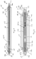
- Figure 1 shows a printing cylinder unit 10 of a printing machine, which comprises a clamping shaft 12 and a rotationally driven part 14.
- the rotationally driven part 14 is a printing cylinder, e.g. a cliché cylinder of a flexographic printing machine or an adapter for such a printing cylinder.
- the clamping shaft 12 comprises a shaft body 16 being rotatable about a shaft axis 18.
- bearing interfaces 20a, 20b which are located at respective axial ends 16a, 16b of the shaft body 16.
- the bearing interfaces are formed as cone sections in the example shown.
- the shaft body 16 is equipped with a drive interface 22, which his only shown schematically.
- the part 14 is clamped to the clamping shaft 12 via two clamping regions 24a, 24b.
- elastically deformable sleeves 26a, 26b are provided, which delimit a fluid chamber 28a, 28b respectively.
- the fluid chambers 28a, 28b are located inside the shaft body 16 and both are filled with a predetermined amount of fluid, e.g. hydraulic oil.
- the sleeves 26a, 26b are deformed to have a first diameter or a second diameter, the second diameter being bigger than the first diameter.
- the part 14 is clamped to the clamping shaft 12 if the clamping regions 24a, 24b have a second diameter and may be axially and/or rotationally moved with respect to the clamping shaft 12 if the clamping regions 24a, 24b have a first diameter.
- This change in diameter is achieved by altering the pressure inside the respective fluid chamber 28a, 28b.
- the second diameter is achieved if the fluid chambers 28a, 28b are pressurized and the first diameter is achieved if the fluid chambers 28a, 28b are de-pressurized, i.e. are substantially at ambient pressure.
- each of them is also delimited by a piston surface of a respective piston 30a, 30b being located inside the shaft body 16 and by a corresponding cylinder part 32a, 32b.
- Each piston 30a, 30b is movable relative to the corresponding cylinder part 32a, 32b, wherein in the example shown, the pistons are movable along a piston axis, which corresponds to the shaft axis 18.
- the cylinder parts 32a, 32b are formed as separate parts in the examples shown, but are axially and rotationally fixed inside the shaft body 16. Alternatively, the cylinder parts 32a, 32b may be formed as sections of the shaft body 16.
- an abutment surface 34a, 34b is formed on each of the cylinder parts 32a, 32b, wherein each of the abutment surfaces 34a, 34b is associated with one of the pistons 30a, 30b and the respective piston 30a, 30b abuts against the associated abutment surface 34a, 34b when the corresponding piston 30a, 30b and cylinder part 32a, 32b are in the second relative position.
- the clamping shaft 12 further comprises a preloading unit 38, which is formed such that it applies a preloading force on both pistons 30a, 30b such that the pistons 30a, 30b are biased towards the second relative position.
- the preloading unit 38 is used for both pistons 30a, 30b and is located between them.
- the preloading unit 38 comprises a spring assembly 40, which is an arrangement of disk springs in the example shown.
- piston 30b is connected to the preloading unit via a bar 42. Consequently, the length of the clamping shaft 12 may be adapted by changing the length of the bar 42.
- fluid chambers 28a, 28b are fluidically connected via a fluid connection line 44.
- the fluid connection line 44 is an axial bore located inside the shaft body 16.
- the fluid connection line 44 makes is possible to put both combinations of a piston 30a, 30b and a cylinder part 32a, 32b in the first relative position by just actuating one of the pistons 30a, 30b.
- both pistons 30a, 30b comprise an actuation interface 46a, 46b, which is a realized as an axial end face of the respective piston 30a, 30b. This end face is provided at an axial end of the shaft body 16 and thus is well accessible for actuation.
- both the piston 30a, 30b actually actuated and also the piston 30a, 30b not directly actuated move towards an axial middle of the clamping shaft 12, thereby attaining the first relative position.
- the clamping shaft 12 is in a clamping state, if it is not actuated and it is in a release state if it is actuated by pushing against at least one of the actuation interfaces 46a, 46b.
- the release state can also be achieved by pushing on both actuation interfaces 46a, 46b.
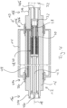
- Figure 4 shows a second embodiment of the printing cylinder unit 10, which differs from the embodiment of Figures 1 to 3 in that a different clamping shaft is used.
- a different clamping shaft is used.
- Corresponding parts will be designated with the same references signs that already have been used in Figures 1 to 3 , where appropriate the suffixes are omitted in Figure 4 .
- Figure 4 differs from the embodiment of Figures 1 to 3 in that there is only one single piston 30 and one single cylinder part 32 cooperating with the piston 30. Both delimit a single fluid chamber 28 and are movable inside the shaft body 16.
- the single fluid chamber 28 is associated with two clamping regions 24a, 24b. More precisely, the single fluid chamber 28 is delimited by two elastically deformable sleeves 26a, 26b. To this end, the fluid chamber 28 comprises an axial bore 48 in the shaft body 16.
- the preloading unit 38 biases the piston 30 against the cylinder part 32.
- the clamping shaft 12 according to Figure 4 may be operated as follows.
- the fluid inside the fluid chamber 28 will be de-pressurized and the diameter of the sleeves 26a, 26b will be elastically decreased. Consequently, the clamping shaft 12 will attain a release state.
Landscapes
- Clamps And Clips (AREA)
- Rolls And Other Rotary Bodies (AREA)
Description
- The invention relates to a clamping shaft for a rotationally driven part, comprising a shaft body being rotatable about a shaft axis, at least one fluid chamber being located inside the shaft body and being filled with a predetermined amount of fluid, wherein the fluid chamber is delimited by a piston surface of at least one piston being located inside the shaft body and a cylinder part, being movable relative to each other such that a volume of the fluid chamber is adjustable by moving the piston relative to the cylinder part, wherein the shaft body comprises at least one elastic clamping region delimiting the fluid chamber, and wherein the clamping region has a first diameter if the piston and the cylinder part are in a first relative position, and a second diameter if the piston and the cylinder part are in a second relative position, the second diameter being bigger than the first diameter.
- Additionally, the invention relates to a printing cylinder unit of a printing machine comprising such a clamping shaft.
- Moreover, the invention relates to a method of operating the clamping shaft mentioned above.
- Such clamping shafts and printing cylinder units being equipped therewith are known in the art. The same applies to methods for operating clamping shafts. The functioning of such clamping shafts is based on selectively pressurizing a fluid, which leads to an elastic expansion of a clamping region of the shaft. In doing so, a printing cylinder or any other rotationally driven part may be clamped to the shaft. The rotationally driven part may be released from the shaft by de-pressurizing the fluid, which leads to a contraction of the clamping region diameter.
- It is noted that the fluid may be compressible or non-compressible. In the case of a non-compressible fluid, a volume of the fluid chamber will remain substantially constant, wherein the volume change resulting from the volume difference between the first and second relative position substantially equals the volume change resulting from the elastic deformation of the clamping region. In the case of a compressible fluid, the volume of the fluid chamber associated with the second relative position is smaller than the volume of the fluid chamber associated with the first relative position of the piston and the cylinder part.
- In this context, the first relative position substantially corresponds to a pressurerelieved state of the fluid, i.e. the fluid is substantially at ambient pressure.
- The fluid is often a hydraulic medium, e.g. hydraulic oil.
- The fluid usually is pressurized by moving the piston, wherein the piston may be driven manually by actuating a screw or spindle being coupled thereto. In order to do so, a tool, e.g. a screw driver, is used. This process is reversible, i.e. the fluid is de-pressurized by moving the piston in an opposite direction.
- From
US 4 386 566 A a clamping shaft for a rotationally driven part is known, comprising a shaft body being rotatable about a shaft axis, at least one fluid chamber being located inside the shaft body and being filled with a predetermined amount of fluid, wherein the fluid chamber is delimited by a piston surface of at least one piston being located inside the shaft body and a cylinder part, being movable relative to each other such that a volume of the fluid chamber is adjustable by moving the piston relative to the cylinder part, wherein the shaft body comprises at least one elastic clamping region delimiting the fluid chamber, wherein the clamping region has a first diameter if the piston and the cylinder part are in a first relative position, and a second diameter if the piston and the cylinder part are in a second relative position, the second diameter being bigger than the first diameter. - In
EP 1 745 929 A1 - It is an object of the present invention to further improve such clamping shafts. Especially, the operation of clamping shafts shall be easy to automate.
- The problem is solved by a clamping shaft according to
claim 1, namely a clamping shaft of the type mentioned above, wherein the clamping shaft further comprises at least one preloading unit, wherein the preloading unit applies a preloading force on the piston and/or the cylinder part such that the piston and the cylinder part are biased towards the second relative position. In other words, the clamping shaft is preloaded towards a clamping state. - Consequently, no external force or energy is necessary in order to bring the clamping shaft into a clamping state in which the clamping region is elastically expanded. In order to bring the clamping shaft into a release state, the preloading force has to be actively counteracted by an external force or energy. Thus, the working principle of known clamping shafts is inverted. Since the preloading unit provides a preloading force internal to the clamping shaft, automation of the clamping process is facilitated.
- The first relative position and the second relative position may be attained via three possibilities. In a first possibility, the piston is moved and the corresponding cylinder part is stationary. In this context, the cylinder part may be formed integrally with the shaft body or as a separate part. In a second possibility, the piston is stationary and the cylinder part is moved. In a third possibility, both the piston and the cylinder part are moved. In the second and third case, the cylinder part must be formed as a separate part, thus not as a portion of the shaft body.
- In a clamping shaft according to an embodiment of the invention, the clamping shaft axis and a piston axis may be coaxial. This variant is especially suitable for clamping shafts rotating at high speed since the coaxial positioning results in a rotationally balanced clamping shaft. Of course, it is also possible to arrange the clamping shaft axis and the piston axis in a non-coaxial manner. This may lead to packaging advantages, i.e. such a clamping shaft only occupies a small installation space.
- In principle, the preloading force may be chosen in function of the specific application case. In the fields of printing machines, the fluid may be pressurized to 200 bar and more. The preloading force will be chosen accordingly.
- According to an embodiment, the clamping shaft comprises two fluid chambers, each being located inside the shaft body and each being filled with a predetermined amount of fluid, wherein each of the fluid chambers is delimited by a piston surface of a piston being located inside the shaft body and a cylinder part, being movable relative to each other such that a volume of the fluid chamber is adjustable by moving the piston relative to the cylinder part, wherein the shaft body comprises two elastic clamping regions each delimiting one of the fluid chambers, wherein the clamping regions have a first diameter if the corresponding piston and the corresponding cylinder part are in a first relative position, and a second diameter if the corresponding piston and the corresponding cylinder part are in a second relative position, the second diameter being bigger than the first diameter, and wherein the preloading unit is located between the pistons or between the cylinder parts and applies a preloading force on the pistons or the cylinder parts such that each of the pistons and the corresponding cylinder parts are biased towards the second relative position. Such a clamping shaft may clamp a rotationally driven part in two clamping regions, which leads to a very reliable coupling between the clamping shaft and the rotationally driven part. Since both pistons use a common preloading unit, the clamping shaft is relatively light and compact.
- Preferably, the piston axis of the two pistons are coaxial.
- The fluid chambers may be fluidically connected via a fluid connection line located inside the shaft body. As a consequence thereof, the pressure in both fluid chambers may be adjusted by using any one of the pistons. This means that it is possible to clamp or release a rotationally driven part form the clamping shaft by just actuating one piston or cylinder part. Consequently, the driven part is coupled to the clamping shaft in a highly reliable way and the clamping shaft is simple to operate.
- Advantageously, an abutment surface associated with each piston is provided in the shaft body, each piston abutting against the respective abutment surface when in the second relative position. A movement of the piston into the clamping direction is thus limited. Consequently, a maximum clamping force or torque may be adjusted by providing such an abutment surface. Consequently, reliable clamping with a constant clamping force is guaranteed.
- According to a preferred embodiment of the invention, the preloading unit comprises a spring assembly. Such a spring assembly may be a disk spring assembly or a coil spring assembly. It is also possible to use gas springs. In the present context, the spring assemblies may also be termed an energy storage since the springs store the energy necessary for providing a second volume of the fluid chamber, i.e. the energy necessary for clamping the rotationally driven part. Such spring assemblies are easy to mount and reliable in operation.
- Each of the clamping regions may be formed integrally with the shaft body or each clamping region may be provided by an elastically deformable sleeve provided on the shaft body. Both alternatives allow for reliably clamping the rotationally driven part to the clamping shaft.
- The shaft body can comprise at least one bearing interface, by which the clamping shaft is rotatably supportable, the shaft body preferably comprising two bearing interfaces. The bearing interfaces are preferably located at axial ends of the clamping shaft. They may essentially be formed as cylinders or cone portions.
- The shaft body also may comprise at least one drive interface by which the clamping shaft is rotationally drivable. The drive interface may be formed as a mounting interface for a gear or a pulley.
- According to a preferred embodiment of the invention, at least one of the pistons and/or the cylinder part cooperating with the piston comprises an actuation interface by which an external force may be applied to the piston and/or the cylinder part counteracting the preloading force such that at least one of the pistons and the corresponding cylinder part are in the first relative position. In other words, via the actuation interface a force is applied to the piston or the cylinder part counteracting the preloading force. Consequently, the clamping shaft is in a release state in which the rotationally driven part is not coupled thereto. The actuation of the clamping shaft may comprise the application of a pushing force, a pulling force or a torque to the actuation interface. These forms of actuation may easily be automated.
- Preferably, the actuation interface is provided in proximity to an axial end of the shaft body. In this context, the actuation interface may axially protrude from the clamping shaft or may be located in a recess provided at an axial end of the shaft body. In both alternatives, the actuation interface is easily accessible for manual or automated actuation.
- Furthermore, the problem is solved by a printing cylinder unit according to claim 11, namely a printing cylinder unit of the type mentioned above, comprising a clamping shaft according to the invention. In such a printing cylinder unit a printing cylinder or an adapter may be selectively coupled to the clamping shaft via the clamping mechanism described above. In this context, a printing cylinder designates all kinds of cylinders used in a printing machine, especially a cliché cylinder of a flexographic printing machine.
- The problem is also solved by a method according to
claim 12, namely a method of operating a clamping shaft according to the invention, wherein the clamping shaft is in a clamping state if the clamping shaft is not actuated and wherein the clamping shaft is in a release state if the clamping shaft is actuated. Consequently, the functioning principle of known clamping shafts is inverted. As has already been explained above, this facilitates the automation of the clamping process. - The clamping shaft may be actuated by pulling an actuation interface along an axial direction of the clamping shaft, by pushing an actuation interface along an axial direction of the clamping shaft or by turning an actuation interface around an axial direction of the clamping shaft. This actuation activities may be performed manually or automatically, e.g. by a robot or any other specific actuation unit.
- The invention will now be explained with reference to two embodiments which are shown in the attached drawings. In the drawings,
-
Figure 1 shows a printing cylinder unit according to an embodiment of the invention comprising a clamping shaft according to the invention being operable by a method for operating a clamping shaft according to the invention, -
Figure 2 the printing cylinder ofFigure 1 in an enlarged representation, wherein a middle section of the printing cylinder is cut out, -
Figure 3 the printing cylinder ofFigures 1 and 2 in a further enlarged representation, wherein a middle section of the printing cylinder is cut out, and -
Figure 4 another embodiment of the printing cylinder unit according to the invention in a schematic representation. -
Figure 1 shows aprinting cylinder unit 10 of a printing machine, which comprises a clampingshaft 12 and a rotationally drivenpart 14. - In the examples shown the rotationally driven
part 14 is a printing cylinder, e.g. a cliché cylinder of a flexographic printing machine or an adapter for such a printing cylinder. - The clamping
shaft 12 comprises ashaft body 16 being rotatable about ashaft axis 18. - It may be rotatably supported inside a printing machine via two
bearing interfaces 20a, 20b which are located at respective axial ends 16a, 16b of theshaft body 16. The bearing interfaces are formed as cone sections in the example shown. - In order to rotatably drive the clamping
shaft 12, theshaft body 16 is equipped with adrive interface 22, which his only shown schematically. - The
part 14 is clamped to the clampingshaft 12 via twoclamping regions 24a, 24b. In theclamping regions 24a, 24b elasticallydeformable sleeves 26a, 26b are provided, which delimit a fluid chamber 28a, 28b respectively. - The fluid chambers 28a, 28b are located inside the
shaft body 16 and both are filled with a predetermined amount of fluid, e.g. hydraulic oil. - Depending on the pressure of the fluid in the respective fluid chambers 28a, 28b, the
sleeves 26a, 26b are deformed to have a first diameter or a second diameter, the second diameter being bigger than the first diameter. - Consequently, the
part 14 is clamped to the clampingshaft 12 if theclamping regions 24a, 24b have a second diameter and may be axially and/or rotationally moved with respect to the clampingshaft 12 if theclamping regions 24a, 24b have a first diameter. - This change in diameter is achieved by altering the pressure inside the respective fluid chamber 28a, 28b. Thus, the second diameter is achieved if the fluid chambers 28a, 28b are pressurized and the first diameter is achieved if the fluid chambers 28a, 28b are de-pressurized, i.e. are substantially at ambient pressure.
- In order to pressurize the fluid chambers 28a, 28b each of them is also delimited by a piston surface of a
respective piston 30a, 30b being located inside theshaft body 16 and by acorresponding cylinder part 32a, 32b. Eachpiston 30a, 30b is movable relative to thecorresponding cylinder part 32a, 32b, wherein in the example shown, the pistons are movable along a piston axis, which corresponds to theshaft axis 18. Thecylinder parts 32a, 32b are formed as separate parts in the examples shown, but are axially and rotationally fixed inside theshaft body 16. Alternatively, thecylinder parts 32a, 32b may be formed as sections of theshaft body 16. - Thus, in the de-pressurized state of one of the fluid chambers 28a, 28b, the
corresponding piston 30a, 30b andcylinder part 32a, 32b are in a first relative position. - In the pressurized state of one of the fluid chambers 28a, 28b, the
corresponding piston 30a, 30b andcylinder part 32a, 32b are in a second relative position. - Additionally, an abutment surface 34a, 34b is formed on each of the
cylinder parts 32a, 32b, wherein each of the abutment surfaces 34a, 34b is associated with one of thepistons 30a, 30b and therespective piston 30a, 30b abuts against the associated abutment surface 34a, 34b when thecorresponding piston 30a, 30b andcylinder part 32a, 32b are in the second relative position. - On the
pistons 30a, 30b counter abutment surfaces 36a, 36b are formed. - The clamping
shaft 12 further comprises a preloading unit 38, which is formed such that it applies a preloading force on bothpistons 30a, 30b such that thepistons 30a, 30b are biased towards the second relative position. - In the example shown in
Figures 1 to 3 , the preloading unit 38 is used for bothpistons 30a, 30b and is located between them. - The preloading unit 38 comprises a spring assembly 40, which is an arrangement of disk springs in the example shown.
- In order to be able to use the functioning principle of the clamping
shaft 12 for different lengths of the clampingshaft 12, piston 30b is connected to the preloading unit via abar 42. Consequently, the length of the clampingshaft 12 may be adapted by changing the length of thebar 42. The remaining parts of the clampingshaft 12, especially thepistons 30a, 30b and the fluid chambers 28a, 28b do not need to be altered. - Moreover, the fluid chambers 28a, 28b are fluidically connected via a
fluid connection line 44. - In the example shown the
fluid connection line 44 is an axial bore located inside theshaft body 16. - As will be explained in the following, the
fluid connection line 44 makes is possible to put both combinations of apiston 30a, 30b and acylinder part 32a, 32b in the first relative position by just actuating one of thepistons 30a, 30b. This means that the clampingshaft 12 can be put into the release state by just actuating onesingle pistons 30a, 30b. - To this end, both
pistons 30a, 30b comprise an actuation interface 46a, 46b, which is a realized as an axial end face of therespective piston 30a, 30b. This end face is provided at an axial end of theshaft body 16 and thus is well accessible for actuation. - Thus, if one of the actuation interfaces 46a, 46b is pushed either manually or automatically, the pressure in both fluid chambers 28a, 28b is reduced.
- Since the forces resulting from the pressure of the fluid are counterbalanced by the preload forces resulting from the preloading unit 38, both the
piston 30a, 30b actually actuated and also thepiston 30a, 30b not directly actuated move towards an axial middle of the clampingshaft 12, thereby attaining the first relative position. - In summary, the clamping
shaft 12 is in a clamping state, if it is not actuated and it is in a release state if it is actuated by pushing against at least one of the actuation interfaces 46a, 46b. Of course, the release state can also be achieved by pushing on both actuation interfaces 46a, 46b. -
Figure 4 shows a second embodiment of theprinting cylinder unit 10, which differs from the embodiment ofFigures 1 to 3 in that a different clamping shaft is used. In the following, only the differences with respect to this first embodiment will be explained. Corresponding parts will be designated with the same references signs that already have been used inFigures 1 to 3 , where appropriate the suffixes are omitted inFigure 4 . - Essentially, the embodiment of
Figure 4 differs from the embodiment ofFigures 1 to 3 in that there is only onesingle piston 30 and onesingle cylinder part 32 cooperating with thepiston 30. Both delimit asingle fluid chamber 28 and are movable inside theshaft body 16. - In contrast to the example of
Figures 1 to 3 , thesingle fluid chamber 28 is associated with two clampingregions 24a, 24b. More precisely, thesingle fluid chamber 28 is delimited by two elasticallydeformable sleeves 26a, 26b. To this end, thefluid chamber 28 comprises anaxial bore 48 in theshaft body 16. - The preloading unit 38 biases the
piston 30 against thecylinder part 32. - The clamping
shaft 12 according toFigure 4 may be operated as follows. - If the clamping
shaft 12 is actuated by pushing on either actuation interface 46a of thepiston 30 or actuation interface 46b of thecylinder part 32, thepiston 30 and thecylinder part 32 will move relative to each other against the preloading force of the preloading unit 38. - In doing so, the fluid inside the
fluid chamber 28 will be de-pressurized and the diameter of thesleeves 26a, 26b will be elastically decreased. Consequently, the clampingshaft 12 will attain a release state. - If none of the actuation interfaces 46a, 46b is pushed, the clamping
shaft 12 is in its clamping state.
Claims (13)
- Clamping shaft (12) for a rotationally driven part (14), comprisinga shaft body (16) being rotatable about a shaft axis (18),at least one fluid chamber (28, 28a, 28b) being located inside the shaft body (16) and being filled with a predetermined amount of fluid,wherein the fluid chamber (28, 28a, 28b) is delimited by a piston surface of at least one piston (30, 30a, 30b) being located inside the shaft body (16) and a cylinder part (32, 32a, 32b), being movable relative to each other such that a volume of the fluid chamber (28, 28a, 28b) is adjustable by moving the piston (30, 30a, 30b) relative to the cylinder part (32, 32a, 32b),wherein the shaft body (16) comprises at least one elastic clamping region (24, 24a, 24b) delimiting the fluid chamber (28, 28a, 28b),wherein the clamping region (24, 24a, 24b) has a first diameter if the piston (30, 30a, 30b) and the cylinder part (32, 32a, 32b) are in a first relative position, and a second diameter if the piston (30, 30a, 30b) and the cylinder part (32, 32a, 32b) are in a second relative position, the second diameter being bigger than the first diameter,characterized in thatthe clamping shaft (12) further comprises at least one preloading unit (38),wherein the preloading unit (38) applies a preloading force on the piston (30, 30a, 30b) and/or the cylinder part (32, 32a, 32b) such that the piston (30, 30a, 30b) and the cylinder part (32, 32a, 32b) are biased towards the second relative position.
- Clamping shaft (12) according to claim 1, comprisingtwo fluid chambers (28, 28a, 28b), each being located inside the shaft body (16) and each being filled with a predetermined amount of fluid,wherein each of the fluid chambers (28, 28a, 28b) is delimited by a piston surface of a piston (30, 30a, 30b) being located inside the shaft body (16) and a cylinder part (32, 32a, 32b), being movable relative to each other such that a volume of the fluid chamber (28, 28a, 28b) is adjustable by moving the piston (30, 30a, 30b) relative to the cylinder part (32, 32a, 32b),wherein the shaft body (16) comprises two elastic clamping regions (24, 24a, 24b) each delimiting one of the fluid chambers (28, 28a, 28b),wherein the clamping regions (24, 24a, 24b) have a first diameter if the corresponding piston (30, 30a, 30b) and the corresponding cylinder part (32, 32a, 32b) are in a first relative position, and a second diameter if the corresponding piston (30, 30a, 30b) and the corresponding cylinder part (32, 32a, 32b) are in a second relative position, the second diameter being bigger than the first diameter, andwherein the preloading unit (38) is located between the pistons (30, 30a, 30b) or between the cylinder parts (32, 32a, 32b) and applies a preloading force on the pistons (30, 30a, 30b) or the cylinder parts (32, 32a, 32b) such that each of the pistons (30, 30a, 30b) and the corresponding cylinder parts (32, 32a, 32b) are biased towards the second relative position.
- Clamping shaft (12) according to claim 2, wherein the fluid chambers (28, 28a, 28b) are fluidically connected via a fluid connection line (44) located inside the shaft body (16).
- Clamping shaft (12) according to any of the preceding claims, wherein an abutment surface (34, 34a, 34b) associated with each piston (30, 30a, 30b) is provided in the shaft body (16), each piston (30, 30a, 30b) abutting against the respective abutment surface (34, 34a, 34b) when in the second relative position.
- Clamping shaft (12) according to any of the preceding claims, wherein the preloading unit (38) comprises a spring assembly (40).
- Clamping shaft (12) according to any of the preceding claims, wherein each of the clamping regions (24, 24a, 24b) is formed integrally with the shaft body (16) or wherein each clamping region (24, 24a, 24b) is provided by an elastically deformable sleeve (26, 26a, 26b) provided on the shaft body (16).
- Clamping shaft (12) according to any of the preceding claims, wherein the shaft body (16) comprises at least one bearing interface (20, 20a, 20b), by which the clamping shaft (12) is rotatably supportable, the shaft body (16) preferably comprising two bearing interfaces (20, 20a, 20b).
- Clamping shaft (12) according to any of the preceding claims, wherein the shaft body (16) comprises at least one drive interface (22) by which the clamping shaft (12) is rotationally drivable.
- Clamping shaft (12) according to any of the preceding claims, wherein at least one of the pistons (30, 30a, 30b) and/or the cylinder part (32, 32a, 32b) cooperating with the piston (30, 30a, 30b) comprises an actuation interface (46, 46a, 46b) by which an external force may be applied to the piston (30, 30a, 30b) and/or the cylinder part (32, 32a, 32b) counteracting the preloading force such that at least one of the pistons (30, 30a, 30b) and the corresponding cylinder part (32, 32a, 32b) are in the first relative position.
- Clamping shaft (12) according to claim 9, wherein the actuation interface (46, 46a, 46b) is provided in proximity to an axial end of the shaft body (16).
- Printing cylinder unit (10) of a printing machine comprising a clamping shaft (12) according to any of the preceding claims.
- Method of operating a clamping shaft (12) according to any of claims 1 to 10 for a rotationally driven part (14),wherein the clamping shaft (12) is in a clamping state, if the clamping shaft (12) is not actuated andwherein the clamping shaft (12) is in a release state if the clamping shaft (12) is actuated.
- Method according to claim 12, wherein the clamping shaft (12) is actuated by pulling an actuation interface (46, 46a, 46b) along an axial direction of the clamping shaft (12), by pushing an actuation interface (46, 46a, 46b) along an axial direction of the clamping shaft (12) or by turning an actuation interface (46, 46a, 46b) around an axial direction of the clamping shaft (12).
Applications Claiming Priority (2)
| Application Number | Priority Date | Filing Date | Title |
|---|---|---|---|
| EP19020339 | 2019-05-23 | ||
| PCT/EP2020/062773 WO2020234004A1 (en) | 2019-05-23 | 2020-05-07 | Clamping shaft, printing cylinder unit and method for operating a clamping shaft |
Publications (2)
| Publication Number | Publication Date |
|---|---|
| EP3972843A1 EP3972843A1 (en) | 2022-03-30 |
| EP3972843B1 true EP3972843B1 (en) | 2024-08-07 |
Family
ID=66655114
Family Applications (1)
| Application Number | Title | Priority Date | Filing Date |
|---|---|---|---|
| EP20723866.8A Active EP3972843B1 (en) | 2019-05-23 | 2020-05-07 | Clamping shaft, printing cylinder unit and method for operating a clamping shaft |
Country Status (6)
| Country | Link |
|---|---|
| US (1) | US12097693B2 (en) |
| EP (1) | EP3972843B1 (en) |
| CN (1) | CN113874216B (en) |
| BR (1) | BR112021021147B1 (en) |
| ES (1) | ES2987285T3 (en) |
| WO (1) | WO2020234004A1 (en) |
Family Cites Families (8)
| Publication number | Priority date | Publication date | Assignee | Title |
|---|---|---|---|---|
| DE1529931B2 (en) * | 1965-09-09 | 1971-03-18 | Fischbach. Alfred, 5252 Runderoth | MOLD CLAMPING AND MOLD HOLDING DEVICE FOR AN INJECTION MOLDING MACHINE |
| US4386566A (en) | 1980-10-06 | 1983-06-07 | Mosstype Corporation | Mandrel assembly for demountable printing cylinder |
| DE19822439A1 (en) * | 1997-07-30 | 1999-02-04 | Heidelberger Druckmasch Ag | Printing machine operating device |
| DE10158844A1 (en) * | 2001-11-27 | 2003-06-12 | Herbert Haenchen Gmbh & Co Kg | Clamping device and adjusting device |
| EP1745929B1 (en) | 2005-07-21 | 2010-12-29 | Fischer & Krecke GmbH | Printing machine |
| EP2090432B1 (en) | 2008-02-12 | 2012-06-06 | Müller Martini Holding AG | Cylinder for a printing unit of a printing machine and method for swapping out the printing sleeve of such a cylinder |
| RU2562497C2 (en) | 2011-06-30 | 2015-09-10 | Кениг Унд Бауэр Акциенгезельшафт | Method of mounting printing form on plate cylinder |
| DE102017100661A1 (en) | 2016-01-14 | 2017-07-20 | manroland sheetfed GmbH | Unlocking a coupling of a double gear |
-
2020
- 2020-05-07 EP EP20723866.8A patent/EP3972843B1/en active Active
- 2020-05-07 BR BR112021021147-0A patent/BR112021021147B1/en active IP Right Grant
- 2020-05-07 WO PCT/EP2020/062773 patent/WO2020234004A1/en not_active Ceased
- 2020-05-07 CN CN202080038217.5A patent/CN113874216B/en active Active
- 2020-05-07 ES ES20723866T patent/ES2987285T3/en active Active
- 2020-05-07 US US17/595,407 patent/US12097693B2/en active Active
Also Published As
| Publication number | Publication date |
|---|---|
| US20220194074A1 (en) | 2022-06-23 |
| BR112021021147A2 (en) | 2021-12-14 |
| WO2020234004A1 (en) | 2020-11-26 |
| BR112021021147B1 (en) | 2023-05-02 |
| ES2987285T3 (en) | 2024-11-14 |
| CN113874216B (en) | 2023-01-06 |
| EP3972843A1 (en) | 2022-03-30 |
| CN113874216A (en) | 2021-12-31 |
| US12097693B2 (en) | 2024-09-24 |
Similar Documents
| Publication | Publication Date | Title |
|---|---|---|
| JP2008073842A (en) | Motor spindle for rotationally driving machine tool tools | |
| CN105102145B (en) | Stamping equipment | |
| US5076166A (en) | Arrangement for the accurately positioned quick-action clamping and tensioning of printing plates | |
| KR20100031494A (en) | Mold clamping device for injection molding machine | |
| US4345453A (en) | Hydraulic press | |
| US5974948A (en) | Linear actuator | |
| CA2984607A1 (en) | Axial swage tool | |
| EP3416781B1 (en) | Device for locking workpieces on machine tools | |
| US20160207156A1 (en) | Rotary table and clamping mechanism | |
| US12097693B2 (en) | Clamping shaft, printing cylinder unit and method for operating a clamping shaft | |
| US20150239085A1 (en) | Lifting apparatus having a toggle lever mechanism | |
| US6647879B1 (en) | Bridge sleeve for printing apparatus | |
| US7363848B2 (en) | Rotating or pivoting device and connection module for a rotating or pivoting device | |
| EP1917450B1 (en) | Self aligning brake kit | |
| US20240117827A1 (en) | Linear Actuator | |
| CN101208169A (en) | Spindle with tension rod and clutch device | |
| EP3406942B1 (en) | Apparatus for converting rotational movement to linear movement | |
| EP0648942B1 (en) | Linear pneumatic actuator with a reversible-action locking device | |
| WO2003046388A1 (en) | Actuator | |
| US7380334B2 (en) | Device for pre-stressing a wheel bearing | |
| US11391357B2 (en) | Adjustment device for bevel gear, automatic adjustment system for bevel gear and adjustment methods for bevel gear | |
| US20250033122A1 (en) | Modular hydraulic chuck | |
| US12529415B2 (en) | Mechatronic drive module | |
| KR100384716B1 (en) | Locking device of index table for machine tool | |
| EP4543632A1 (en) | Device for clamping workpieces on machine tools |
Legal Events
| Date | Code | Title | Description |
|---|---|---|---|
| STAA | Information on the status of an ep patent application or granted ep patent |
Free format text: STATUS: UNKNOWN |
|
| STAA | Information on the status of an ep patent application or granted ep patent |
Free format text: STATUS: THE INTERNATIONAL PUBLICATION HAS BEEN MADE |
|
| PUAI | Public reference made under article 153(3) epc to a published international application that has entered the european phase |
Free format text: ORIGINAL CODE: 0009012 |
|
| STAA | Information on the status of an ep patent application or granted ep patent |
Free format text: STATUS: REQUEST FOR EXAMINATION WAS MADE |
|
| 17P | Request for examination filed |
Effective date: 20211206 |
|
| AK | Designated contracting states |
Kind code of ref document: A1 Designated state(s): AL AT BE BG CH CY CZ DE DK EE ES FI FR GB GR HR HU IE IS IT LI LT LU LV MC MK MT NL NO PL PT RO RS SE SI SK SM TR |
|
| DAV | Request for validation of the european patent (deleted) | ||
| DAX | Request for extension of the european patent (deleted) | ||
| GRAP | Despatch of communication of intention to grant a patent |
Free format text: ORIGINAL CODE: EPIDOSNIGR1 |
|
| STAA | Information on the status of an ep patent application or granted ep patent |
Free format text: STATUS: GRANT OF PATENT IS INTENDED |
|
| INTG | Intention to grant announced |
Effective date: 20240503 |
|
| GRAS | Grant fee paid |
Free format text: ORIGINAL CODE: EPIDOSNIGR3 |
|
| GRAA | (expected) grant |
Free format text: ORIGINAL CODE: 0009210 |
|
| STAA | Information on the status of an ep patent application or granted ep patent |
Free format text: STATUS: THE PATENT HAS BEEN GRANTED |
|
| AK | Designated contracting states |
Kind code of ref document: B1 Designated state(s): AL AT BE BG CH CY CZ DE DK EE ES FI FR GB GR HR HU IE IS IT LI LT LU LV MC MK MT NL NO PL PT RO RS SE SI SK SM TR |
|
| REG | Reference to a national code |
Ref country code: GB Ref legal event code: FG4D |
|
| REG | Reference to a national code |
Ref country code: CH Ref legal event code: EP |
|
| REG | Reference to a national code |
Ref country code: IE Ref legal event code: FG4D |
|
| REG | Reference to a national code |
Ref country code: DE Ref legal event code: R096 Ref document number: 602020035287 Country of ref document: DE |
|
| REG | Reference to a national code |
Ref country code: ES Ref legal event code: FG2A Ref document number: 2987285 Country of ref document: ES Kind code of ref document: T3 Effective date: 20241114 |
|
| REG | Reference to a national code |
Ref country code: LT Ref legal event code: MG9D |
|
| REG | Reference to a national code |
Ref country code: NL Ref legal event code: MP Effective date: 20240807 |
|
| PG25 | Lapsed in a contracting state [announced via postgrant information from national office to epo] |
Ref country code: NO Free format text: LAPSE BECAUSE OF FAILURE TO SUBMIT A TRANSLATION OF THE DESCRIPTION OR TO PAY THE FEE WITHIN THE PRESCRIBED TIME-LIMIT Effective date: 20241107 |
|
| REG | Reference to a national code |
Ref country code: AT Ref legal event code: MK05 Ref document number: 1710520 Country of ref document: AT Kind code of ref document: T Effective date: 20240807 |
|
| PG25 | Lapsed in a contracting state [announced via postgrant information from national office to epo] |
Ref country code: NL Free format text: LAPSE BECAUSE OF FAILURE TO SUBMIT A TRANSLATION OF THE DESCRIPTION OR TO PAY THE FEE WITHIN THE PRESCRIBED TIME-LIMIT Effective date: 20240807 Ref country code: FI Free format text: LAPSE BECAUSE OF FAILURE TO SUBMIT A TRANSLATION OF THE DESCRIPTION OR TO PAY THE FEE WITHIN THE PRESCRIBED TIME-LIMIT Effective date: 20240807 Ref country code: PL Free format text: LAPSE BECAUSE OF FAILURE TO SUBMIT A TRANSLATION OF THE DESCRIPTION OR TO PAY THE FEE WITHIN THE PRESCRIBED TIME-LIMIT Effective date: 20240807 Ref country code: PT Free format text: LAPSE BECAUSE OF FAILURE TO SUBMIT A TRANSLATION OF THE DESCRIPTION OR TO PAY THE FEE WITHIN THE PRESCRIBED TIME-LIMIT Effective date: 20241209 Ref country code: GR Free format text: LAPSE BECAUSE OF FAILURE TO SUBMIT A TRANSLATION OF THE DESCRIPTION OR TO PAY THE FEE WITHIN THE PRESCRIBED TIME-LIMIT Effective date: 20241108 |
|
| PG25 | Lapsed in a contracting state [announced via postgrant information from national office to epo] |
Ref country code: BG Free format text: LAPSE BECAUSE OF FAILURE TO SUBMIT A TRANSLATION OF THE DESCRIPTION OR TO PAY THE FEE WITHIN THE PRESCRIBED TIME-LIMIT Effective date: 20240807 |
|
| PG25 | Lapsed in a contracting state [announced via postgrant information from national office to epo] |
Ref country code: LV Free format text: LAPSE BECAUSE OF FAILURE TO SUBMIT A TRANSLATION OF THE DESCRIPTION OR TO PAY THE FEE WITHIN THE PRESCRIBED TIME-LIMIT Effective date: 20240807 |
|
| PG25 | Lapsed in a contracting state [announced via postgrant information from national office to epo] |
Ref country code: IS Free format text: LAPSE BECAUSE OF FAILURE TO SUBMIT A TRANSLATION OF THE DESCRIPTION OR TO PAY THE FEE WITHIN THE PRESCRIBED TIME-LIMIT Effective date: 20241207 Ref country code: AT Free format text: LAPSE BECAUSE OF FAILURE TO SUBMIT A TRANSLATION OF THE DESCRIPTION OR TO PAY THE FEE WITHIN THE PRESCRIBED TIME-LIMIT Effective date: 20240807 |
|
| PG25 | Lapsed in a contracting state [announced via postgrant information from national office to epo] |
Ref country code: HR Free format text: LAPSE BECAUSE OF FAILURE TO SUBMIT A TRANSLATION OF THE DESCRIPTION OR TO PAY THE FEE WITHIN THE PRESCRIBED TIME-LIMIT Effective date: 20240807 |
|
| PG25 | Lapsed in a contracting state [announced via postgrant information from national office to epo] |
Ref country code: RS Free format text: LAPSE BECAUSE OF FAILURE TO SUBMIT A TRANSLATION OF THE DESCRIPTION OR TO PAY THE FEE WITHIN THE PRESCRIBED TIME-LIMIT Effective date: 20241107 |
|
| PG25 | Lapsed in a contracting state [announced via postgrant information from national office to epo] |
Ref country code: RS Free format text: LAPSE BECAUSE OF FAILURE TO SUBMIT A TRANSLATION OF THE DESCRIPTION OR TO PAY THE FEE WITHIN THE PRESCRIBED TIME-LIMIT Effective date: 20241107 Ref country code: PT Free format text: LAPSE BECAUSE OF FAILURE TO SUBMIT A TRANSLATION OF THE DESCRIPTION OR TO PAY THE FEE WITHIN THE PRESCRIBED TIME-LIMIT Effective date: 20241209 Ref country code: PL Free format text: LAPSE BECAUSE OF FAILURE TO SUBMIT A TRANSLATION OF THE DESCRIPTION OR TO PAY THE FEE WITHIN THE PRESCRIBED TIME-LIMIT Effective date: 20240807 Ref country code: NO Free format text: LAPSE BECAUSE OF FAILURE TO SUBMIT A TRANSLATION OF THE DESCRIPTION OR TO PAY THE FEE WITHIN THE PRESCRIBED TIME-LIMIT Effective date: 20241107 Ref country code: NL Free format text: LAPSE BECAUSE OF FAILURE TO SUBMIT A TRANSLATION OF THE DESCRIPTION OR TO PAY THE FEE WITHIN THE PRESCRIBED TIME-LIMIT Effective date: 20240807 Ref country code: LV Free format text: LAPSE BECAUSE OF FAILURE TO SUBMIT A TRANSLATION OF THE DESCRIPTION OR TO PAY THE FEE WITHIN THE PRESCRIBED TIME-LIMIT Effective date: 20240807 Ref country code: IS Free format text: LAPSE BECAUSE OF FAILURE TO SUBMIT A TRANSLATION OF THE DESCRIPTION OR TO PAY THE FEE WITHIN THE PRESCRIBED TIME-LIMIT Effective date: 20241207 Ref country code: HR Free format text: LAPSE BECAUSE OF FAILURE TO SUBMIT A TRANSLATION OF THE DESCRIPTION OR TO PAY THE FEE WITHIN THE PRESCRIBED TIME-LIMIT Effective date: 20240807 Ref country code: GR Free format text: LAPSE BECAUSE OF FAILURE TO SUBMIT A TRANSLATION OF THE DESCRIPTION OR TO PAY THE FEE WITHIN THE PRESCRIBED TIME-LIMIT Effective date: 20241108 Ref country code: FI Free format text: LAPSE BECAUSE OF FAILURE TO SUBMIT A TRANSLATION OF THE DESCRIPTION OR TO PAY THE FEE WITHIN THE PRESCRIBED TIME-LIMIT Effective date: 20240807 Ref country code: BG Free format text: LAPSE BECAUSE OF FAILURE TO SUBMIT A TRANSLATION OF THE DESCRIPTION OR TO PAY THE FEE WITHIN THE PRESCRIBED TIME-LIMIT Effective date: 20240807 Ref country code: AT Free format text: LAPSE BECAUSE OF FAILURE TO SUBMIT A TRANSLATION OF THE DESCRIPTION OR TO PAY THE FEE WITHIN THE PRESCRIBED TIME-LIMIT Effective date: 20240807 |
|
| PG25 | Lapsed in a contracting state [announced via postgrant information from national office to epo] |
Ref country code: DK Free format text: LAPSE BECAUSE OF FAILURE TO SUBMIT A TRANSLATION OF THE DESCRIPTION OR TO PAY THE FEE WITHIN THE PRESCRIBED TIME-LIMIT Effective date: 20240807 Ref country code: SM Free format text: LAPSE BECAUSE OF FAILURE TO SUBMIT A TRANSLATION OF THE DESCRIPTION OR TO PAY THE FEE WITHIN THE PRESCRIBED TIME-LIMIT Effective date: 20240807 |
|
| PG25 | Lapsed in a contracting state [announced via postgrant information from national office to epo] |
Ref country code: EE Free format text: LAPSE BECAUSE OF FAILURE TO SUBMIT A TRANSLATION OF THE DESCRIPTION OR TO PAY THE FEE WITHIN THE PRESCRIBED TIME-LIMIT Effective date: 20240807 |
|
| PG25 | Lapsed in a contracting state [announced via postgrant information from national office to epo] |
Ref country code: SK Free format text: LAPSE BECAUSE OF FAILURE TO SUBMIT A TRANSLATION OF THE DESCRIPTION OR TO PAY THE FEE WITHIN THE PRESCRIBED TIME-LIMIT Effective date: 20240807 |
|
| PGFP | Annual fee paid to national office [announced via postgrant information from national office to epo] |
Ref country code: GB Payment date: 20250313 Year of fee payment: 6 |
|
| REG | Reference to a national code |
Ref country code: DE Ref legal event code: R097 Ref document number: 602020035287 Country of ref document: DE |
|
| PLBE | No opposition filed within time limit |
Free format text: ORIGINAL CODE: 0009261 |
|
| STAA | Information on the status of an ep patent application or granted ep patent |
Free format text: STATUS: NO OPPOSITION FILED WITHIN TIME LIMIT |
|
| PGFP | Annual fee paid to national office [announced via postgrant information from national office to epo] |
Ref country code: DE Payment date: 20250311 Year of fee payment: 6 |
|
| PGFP | Annual fee paid to national office [announced via postgrant information from national office to epo] |
Ref country code: ES Payment date: 20250605 Year of fee payment: 6 |
|
| 26N | No opposition filed |
Effective date: 20250508 |
|
| PGFP | Annual fee paid to national office [announced via postgrant information from national office to epo] |
Ref country code: FR Payment date: 20250505 Year of fee payment: 6 |
|
| PGFP | Annual fee paid to national office [announced via postgrant information from national office to epo] |
Ref country code: CZ Payment date: 20250423 Year of fee payment: 6 |
|
| PG25 | Lapsed in a contracting state [announced via postgrant information from national office to epo] |
Ref country code: SE Free format text: LAPSE BECAUSE OF FAILURE TO SUBMIT A TRANSLATION OF THE DESCRIPTION OR TO PAY THE FEE WITHIN THE PRESCRIBED TIME-LIMIT Effective date: 20240807 |
|
| REG | Reference to a national code |
Ref country code: CH Ref legal event code: H13 Free format text: ST27 STATUS EVENT CODE: U-0-0-H10-H13 (AS PROVIDED BY THE NATIONAL OFFICE) Effective date: 20251223 |
|
| PG25 | Lapsed in a contracting state [announced via postgrant information from national office to epo] |
Ref country code: LU Free format text: LAPSE BECAUSE OF NON-PAYMENT OF DUE FEES Effective date: 20250507 |
|
| PG25 | Lapsed in a contracting state [announced via postgrant information from national office to epo] |
Ref country code: CH Free format text: LAPSE BECAUSE OF NON-PAYMENT OF DUE FEES Effective date: 20250531 |
|
| REG | Reference to a national code |
Ref country code: BE Ref legal event code: MM Effective date: 20250531 |
|
| PG25 | Lapsed in a contracting state [announced via postgrant information from national office to epo] |
Ref country code: MC Free format text: LAPSE BECAUSE OF FAILURE TO SUBMIT A TRANSLATION OF THE DESCRIPTION OR TO PAY THE FEE WITHIN THE PRESCRIBED TIME-LIMIT Effective date: 20240807 |
|
| PG25 | Lapsed in a contracting state [announced via postgrant information from national office to epo] |
Ref country code: IE Free format text: LAPSE BECAUSE OF NON-PAYMENT OF DUE FEES Effective date: 20250507 |
|
| PG25 | Lapsed in a contracting state [announced via postgrant information from national office to epo] |
Ref country code: RO Free format text: LAPSE BECAUSE OF FAILURE TO SUBMIT A TRANSLATION OF THE DESCRIPTION OR TO PAY THE FEE WITHIN THE PRESCRIBED TIME-LIMIT Effective date: 20240807 Ref country code: BE Free format text: LAPSE BECAUSE OF NON-PAYMENT OF DUE FEES Effective date: 20250531 Ref country code: IT Free format text: LAPSE BECAUSE OF NON-PAYMENT OF DUE FEES Effective date: 20250507 |