EP3972715B1 - Air oil separator - Google Patents
Air oil separator Download PDFInfo
- Publication number
- EP3972715B1 EP3972715B1 EP20731672.0A EP20731672A EP3972715B1 EP 3972715 B1 EP3972715 B1 EP 3972715B1 EP 20731672 A EP20731672 A EP 20731672A EP 3972715 B1 EP3972715 B1 EP 3972715B1
- Authority
- EP
- European Patent Office
- Prior art keywords
- flange
- oil separator
- end cap
- air oil
- recess
- Prior art date
- Legal status (The legal status is an assumption and is not a legal conclusion. Google has not performed a legal analysis and makes no representation as to the accuracy of the status listed.)
- Active
Links
Images





Classifications
-
- B—PERFORMING OPERATIONS; TRANSPORTING
- B01—PHYSICAL OR CHEMICAL PROCESSES OR APPARATUS IN GENERAL
- B01D—SEPARATION
- B01D46/00—Filters or filtering processes specially modified for separating dispersed particles from gases or vapours
- B01D46/24—Particle separators, e.g. dust precipitators, using rigid hollow filter bodies
- B01D46/2403—Particle separators, e.g. dust precipitators, using rigid hollow filter bodies characterised by the physical shape or structure of the filtering element
- B01D46/2411—Filter cartridges
- B01D46/2414—End caps including additional functions or special forms
-
- B—PERFORMING OPERATIONS; TRANSPORTING
- B01—PHYSICAL OR CHEMICAL PROCESSES OR APPARATUS IN GENERAL
- B01D—SEPARATION
- B01D46/00—Filters or filtering processes specially modified for separating dispersed particles from gases or vapours
- B01D46/0027—Filters or filtering processes specially modified for separating dispersed particles from gases or vapours with additional separating or treating functions
- B01D46/003—Filters or filtering processes specially modified for separating dispersed particles from gases or vapours with additional separating or treating functions including coalescing means for the separation of liquid
-
- B—PERFORMING OPERATIONS; TRANSPORTING
- B01—PHYSICAL OR CHEMICAL PROCESSES OR APPARATUS IN GENERAL
- B01D—SEPARATION
- B01D46/00—Filters or filtering processes specially modified for separating dispersed particles from gases or vapours
- B01D46/0027—Filters or filtering processes specially modified for separating dispersed particles from gases or vapours with additional separating or treating functions
- B01D46/003—Filters or filtering processes specially modified for separating dispersed particles from gases or vapours with additional separating or treating functions including coalescing means for the separation of liquid
- B01D46/0031—Filters or filtering processes specially modified for separating dispersed particles from gases or vapours with additional separating or treating functions including coalescing means for the separation of liquid with collecting, draining means
-
- B—PERFORMING OPERATIONS; TRANSPORTING
- B01—PHYSICAL OR CHEMICAL PROCESSES OR APPARATUS IN GENERAL
- B01D—SEPARATION
- B01D46/00—Filters or filtering processes specially modified for separating dispersed particles from gases or vapours
- B01D46/24—Particle separators, e.g. dust precipitators, using rigid hollow filter bodies
- B01D46/2403—Particle separators, e.g. dust precipitators, using rigid hollow filter bodies characterised by the physical shape or structure of the filtering element
- B01D46/2411—Filter cartridges
-
- B—PERFORMING OPERATIONS; TRANSPORTING
- B01—PHYSICAL OR CHEMICAL PROCESSES OR APPARATUS IN GENERAL
- B01D—SEPARATION
- B01D2265/00—Casings, housings or mounting for filters specially adapted for separating dispersed particles from gases or vapours
- B01D2265/02—Non-permanent measures for connecting different parts of the filter
- B01D2265/021—Anti-rotational means
-
- B—PERFORMING OPERATIONS; TRANSPORTING
- B01—PHYSICAL OR CHEMICAL PROCESSES OR APPARATUS IN GENERAL
- B01D—SEPARATION
- B01D2265/00—Casings, housings or mounting for filters specially adapted for separating dispersed particles from gases or vapours
- B01D2265/02—Non-permanent measures for connecting different parts of the filter
- B01D2265/024—Mounting aids
- B01D2265/026—Mounting aids with means for avoiding false mounting
-
- B—PERFORMING OPERATIONS; TRANSPORTING
- B01—PHYSICAL OR CHEMICAL PROCESSES OR APPARATUS IN GENERAL
- B01D—SEPARATION
- B01D2271/00—Sealings for filters specially adapted for separating dispersed particles from gases or vapours
- B01D2271/02—Gaskets, sealings
- B01D2271/027—Radial sealings
Definitions
- This disclosure relates to the gas/liquid separation. This disclosure particularly concerns and air oil separator for use in air compressors.
- Certain air oil separators for example as used with air compressors, include two components: a vessel or tank with a cover; and a removable and replaceable separator element. In some assemblies, a single separator element is used, while in others, multiple elements are used.
- operation involves directing a gas/liquid flow (e.g., air entrained with oil) into the tank. The gas flow is eventually directed through the filter element, and within the filter element liquid coalescing and drainage occurs. As a result, entrained liquid concentration, within the air, is reduced. Periodically, the filter element is removed and replaced with a new filter element.
- a gas/liquid flow e.g., air entrained with oil
- US20100154372A1 discloses a filter assembly for removing material entrained in a fluid stream, comprising a housing for a filter element, having a head part and a body part for receiving a filter element, and inlet and outlet ports for the fluid that is to be filtered.
- the head part and the body part each have engagement formations which enable the head and body parts to be connected to one another and separated by relative rotation about an axis which is coaxial with a head axis and a body axis.
- Head and body part keying formations can be provided in the form of at least one recess which is provided in a rib on one of the head and body parts, and at least one projection which is provided on the other of the head and body parts.
- the keying formations require alignment of the head and body axes for initial assembly of the head and body parts when the projection is can be received in the recess in the rib so as to restrict relative rotation of the head and body parts, and so that the head and body parts can then to be moved to an assembly position in which the projection has passed through the rib so that the head and body parts can be rotated relative to each other to allow the engagement formations to become engaged to one another.
- US2016/348550A1 describes a filter element for an oil separator of a crankcase ventilation system in which a filter element is configured to separate oil from fluid and that has a covering surface extending parallel to a direction of flow, together with at least one cover element covering surface in at least some regions.
- An oil separator is taught having the filter element with at least one pressure control valve controlling crankcase pressure and has a valve closing body that operates in conjunction with a valve seat.
- US20160256813A1 discloses a filter insert for installation in a housing, having at least one substantially hollow cylindrical filter element for separating liquid from aerosol; and at least one covering element designed to cover an axial end region of the filter element; wherein at least one of the at least one covering element is formed from at least one metal sheet and connected with the filter element with at least one mechanical connection; wherein the mechanical connection between the at least one covering element and the filter element is formed solely by a structure of the at least one covering element produced through deforming or reforming the at least one covering element; wherein the structure of the at least one covering element is configured to clamp the filter element to the at least one covering element.
- US20140157738A1 discloses a filter for removing oil from air exiting an air compressor or a vacuum pump including a housing and at least one filter element, the end region of which is adhesively bonded to a flange.
- the flange has a flanged edge and a bead which is adjacently arranged to the edge, the edge and the bead together forming a groove into which the filter element and an adhesive is introduced.
- FIG. 20 an example embodiment, which is not part of the invention, of an air oil separator assembly is shown generally at 30.
- the assembly 30 includes a vessel or tank 32.
- the tank 32 includes a housing 33 and a cover 34.
- the housing 33 has a surrounding wall 35 that defines an interior volume 36.
- the housing 33 has a closed bottom 37 and an open mouth 38 in communication with the interior volume 36.
- the tank 32 further includes an inlet 40 extending through the wall 35.
- the inlet 40 takes in an oil-entrained air stream into the interior volume 36.
- a lower liquid sump 41 is in the interior volume 36 and held by the closed bottom 37.
- the liquid sump 41 is typically coalesced oil that is has been removed from the air stream being brought into the assembly 30.
- the tank 32 further includes a flange 42.
- the flange 42 circumscribes the mouth 38.
- the cover 34 is removably mounted on the tank 32 and over the mouth 38 to provided selective access to the interior volume 36.
- the cover 34 is positionable on the flange 42.
- the cover 34 has an opening 44.
- the opening 44 can be an air flow outlet 45.
- the cover 34 has no openings (e.g., is closed), and the air flow outlet is in a different part of the air oil separator assembly 30.
- a removable and replaceable filter element 46 Positioned within the interior volume 36 of the tank 32 is a removable and replaceable filter element 46.
- the filter element 46 will separate gas from liquid (e.g. air from oil) that is being brought into the tank 32 through the inlet 40.
- the air and oil inlet stream flows into the inlet 40 and into the interior volume 36. From there, it passes through the filter element 46.
- the filter element 46 separates the air from the oil, and coalesces the oil causing it to drain to the bottom of the tank 32 and be collected in the sump 41.
- the air that has had the oil removed then exits the tank 32 through the outlet 45.
- the filter element 46 includes a tubular construction of filter media 48.
- the filter media 48 can often be a pleated media formed in a cylinder.
- a filter interior 50 In the interior of the tubular construction of media 48 is a filter interior 50, which is typically a clean air volume.
- the filter media 48 has opposite first and second ends 51, 52.
- the filter element 50 further has a longitudinal axis 54 extending along the length thereof.
- the longitudinal axis 54 passes through a center of the filter interior 50 and is perpendicular to a plane containing the first end 51 and perpendicular to a plane containing the second end 52.
- the filter media 48 is typically a type of filter media that will separate oil from a gas stream.
- the filter media 46 can be embodied as a media configuration, having multiple layered media grades and types.
- the filter media will typically cause the oil within the gas stream to coalesce, which will then form droplets and drip by gravity into the sump 41.
- the media 48 can be a pleated media, but can include non-pleated as well. When pleated media is use, a direction of the pleats extend parallel to the longitudinal axis 54 in a direction between the first and second ends 51, 52.
- the flow through the filter element 46 is from the outside, through the media 48 and then into the filter interior 50. From the filter interior 50, it exits the assembly 30 through the outlet 45.
- Other arrangements can include the flow through the element 46 from the inside to the outside.
- the filter media 48 will often be supported by at least an inner liner 56.
- the inner liner 56 will help prevent the collapse of the pleats of the media 48.
- the filter element 46 can further include an outer liner 58.
- the outer liner 58 is along an outer diameter of the pleated media 48 and extends between the first and second ends 51, 52.
- the filter element 46 further includes a first end cap construction 60.
- the first end cap construction 60 is secured to first end 51 of the media 48.
- a second end 52 of the media 48 is a second end cap 62.
- the second end cap 62 is a closed end cap.
- the filter element 46 includes the first end cap construction 60 as defining a flange-receiving recess therein.
- the first end cap construction 60 in this embodiment, includes an axial plate 72 and an annular sleeve 73.
- the annular sleeve 73 extends perpendicular from the plate 72 in a direction toward the filter media 48.
- the annular sleeve 73 includes an outer radial ring 74 adjacent to the outer liner 58 and an inner radial ring 75 adjacent to and radially inward of the inner liner 56.
- the filter media 48 is located between the outer radial ring 74 and the inner radial ring 75.
- the recess 70 is defined by the annular sleeve 73.
- the recess 70 is a longitudinally extending recess generally parallel to the longitudinal axis 54.
- the recess 70 in the embodiment of FIGS. 1 and 2 is defined by the outer radial ring 74.
- the recess 70 is defined by the axial plate 72.
- the axial plate 72 includes an upper surface 78 and an opposite lower surface 79.
- the lower surface 79 faces the filter media 48.
- the recess 70 is a continuous ring in the lower surface 79 of the plate 72.
- the upper surface 78 of the plate 72 can include an axially extending rib 80 forming a continuous ring.
- the recess 70 can include a variety of cross section including, for example, rounded, polygon, trapezoidal, curved, or irregular.
- the filter element 46 of the embodiments shown in FIGS. 1-4 can be removably positioned in the interior volume 36 of the tank 32 of an air oil assembly 30.
- the flange 42 of the tank 32 include a projection 82.
- the projection 82 on the flange 42 extends into the flange-receiving recess 70 of the first end cap construction 60 of the filter element 46.
- the air oil separator assembly 30 further includes a first seal member 84 between and against the flange 42 and the first end cap construction 60.
- the first seal member 84 can include, for example, a gasket or an O-ring.
- a second seal member 85 is between and against the first end cap construction 60 and the cover 34.
- the second seal member 85 can be in the form of a gasket or O-ring seal member.
- the projection 82 on the flange 42 extends radially inwardly from the flange 42 and extends radially inwardly into the open mouth 38 of the tank 32.
- the projection 42 is received by the recess 70 in the outer radial ring 74 of the sleeve 73.
- the projection 82 on the flange 42 extends axially upwardly into the recess 70, which is in the form of continuous ring in the lower surface 79 of the plate 72.
- the cover 34 further includes a continuous recess 86 in the portion of the cover 34 that engages against the flange 42 of the tank 32.
- the recess 86 in the cover 34 receives the rib 80 of the upper surface 78 of the plate 72.
- the projection 82 on the flange 42 can have a cross section of many different shapes including, for example, rounded, polygon, trapezoidal, curved, or irregular.
- the filter element 46 has at its first end cap construction 60 a plurality of alternating radially outward projections 90 and radially inward recesses 91.
- the alternating projections 90 and recesses 91 are along a radially outward periphery 92 of the axial plate 72 of the first end cap construction 60.
- the projections 90 and recesses 91 are curved surfaces.
- the projections 90 and recesses 91 give the appearance of a wave.
- FIG. 9 there is at least one of the projections that extends radially outwardly more than a majority of remainder of the projections 90.
- a single projection 94 extends radially outwardly more than all of a remainder of the projections 90. This projection 94 helps to perform a handle or grasping member to allow the filter element 46 to be more easily removed from the tank 32.
- the flange 42 of the tank 32 has a lid-engaging section 96 and an element engaging section 98.
- the element engaging section 98 is axially recessed from and radially inward of the lid engaging section 96.
- the element engaging section 98 has a groove 100 holding a seal member 101 therein.
- Each of the lid engaging section 96 and element engaging section 98 has a plurality of alternating radially inward protrusions 102 and radially outward depressions 103.
- the filter element of the assembly of FIGS. 5-19 is removably positioned in the interior volume 36 of the tank 32 with a portion of the first end cap construction 60 axially against the seal member 101 in the element engaging section 98 of the tank flange 42 and is circumscribed by the lid engaging section 96.
- the radially outward projections 90 of the first end cap construction 60 are received by the depressions 103 of the lid engaging section 96.
- the radially inward recesses 91 of the first end cap construction 60 receive the protrusions 102 of the lid engaging section 96.
- the lid engaging section 96 of the flange 42 includes a plurality of fastener holes 106 in an axial section thereof.
- the cover 34 includes holes 107 that receive axially extending fasteners, such as bolts 108 removably mounted in the fastener holes 106, 107 to allow the cover 34 to be removably fastened to the tank 32.
- the groove 100 and seal member 101 form a wavy ring 110.
- the lid-engaging section 96 can have a section 112 that is machined through to allow the protruding projection 94 to extend radially beyond or outside an outer diameter of the wall 35 of the tank 32.
- the first end cap construction 60 in this aspect, includes an outer radial portion 120 including a continuous extension 121 extending radially outwardly from the outer diameter of the filter medial 48.
- the continuous extension 121 has a first section 122 defining an outer periphery 123 of the extension 121.
- the continuous extension 121 further includes a second section 124 between the first section 122 and the outer diameter of the filter media 48.
- the first section 122 is contained within a plane that is perpendicular to the longitudinal axis 54.
- the second section 124 slopes from the first section 92 in a direction toward the second end 52 of the filter media 48.
- the first end cap construction 60 further includes a centering ring 126.
- the centering ring 126 is radially inward from the inner diameter of the filter media 48.
- the central ring 126 defines an opening 128 in communication with the interior 50 of the tubular construction of filter media 48.
- the centering ring 146 helps to center the cover 34 over the element 46 and tank wall 35.
- the flange 42 in this aspect, has a first radially outward surface 130 and a frusto-conical surface 132.
- the frusto-conical surface 132 is between the first surface 130 and the inner diameter of the flange 42.
- the filter element 46 is positioned in the interior volume 36 with the first section 122 of the first end cap construction 60 being against the first surface 130 of the flange 42.
- the second section 124 is received by the frusto-conical surface 132 of the flange 42.
- the cover 34 is removably mounted on the tank 32 over the mouth 38 to provide selective access to the interior volume 36.
- the cover 34 has an element engaging side 134 with an axial protrusion 136 extending into and being received by the second section 124 of the first end cap construction 60.
- the air oil separator assembly 30 further includes a first seal member 138, which can be an O-ring, between the second section 124 of the first end cap construction 60 and the cover 34.
- a second seal member 140 can be between the second section 124 of the first end cap construction 60 and the flange 42.
- the second seal member 140 can be against the frusto-conical section 132 of the flange 42.
- the first end cap construction 60 can have the centering ring 126 extend further radially inwardly such that it provides all, or at least a portion, of an outlet flow surface 142 of the outlet 45.
- the outlet flow surface 142 is a curved surface of the cover 34, but in the alternate aspect, the end cap construction 60 itself would form the curved surface of the outlet 45 and lead to the opening 44 in the cover 34.
Landscapes
- Chemical & Material Sciences (AREA)
- Chemical Kinetics & Catalysis (AREA)
- Physics & Mathematics (AREA)
- Geometry (AREA)
- Filtering Of Dispersed Particles In Gases (AREA)
- Lubrication Details And Ventilation Of Internal Combustion Engines (AREA)
- Closures For Containers (AREA)
Description
- This disclosure relates to the gas/liquid separation. This disclosure particularly concerns and air oil separator for use in air compressors.
- Certain air oil separators, for example as used with air compressors, include two components: a vessel or tank with a cover; and a removable and replaceable separator element. In some assemblies, a single separator element is used, while in others, multiple elements are used. In general, operation involves directing a gas/liquid flow (e.g., air entrained with oil) into the tank. The gas flow is eventually directed through the filter element, and within the filter element liquid coalescing and drainage occurs. As a result, entrained liquid concentration, within the air, is reduced. Periodically, the filter element is removed and replaced with a new filter element.
-
US20100154372A1 discloses a filter assembly for removing material entrained in a fluid stream, comprising a housing for a filter element, having a head part and a body part for receiving a filter element, and inlet and outlet ports for the fluid that is to be filtered. The head part and the body part each have engagement formations which enable the head and body parts to be connected to one another and separated by relative rotation about an axis which is coaxial with a head axis and a body axis. Head and body part keying formations can be provided in the form of at least one recess which is provided in a rib on one of the head and body parts, and at least one projection which is provided on the other of the head and body parts. The keying formations require alignment of the head and body axes for initial assembly of the head and body parts when the projection is can be received in the recess in the rib so as to restrict relative rotation of the head and body parts, and so that the head and body parts can then to be moved to an assembly position in which the projection has passed through the rib so that the head and body parts can be rotated relative to each other to allow the engagement formations to become engaged to one another. -
US2016/348550A1 describes a filter element for an oil separator of a crankcase ventilation system in which a filter element is configured to separate oil from fluid and that has a covering surface extending parallel to a direction of flow, together with at least one cover element covering surface in at least some regions. An oil separator is taught having the filter element with at least one pressure control valve controlling crankcase pressure and has a valve closing body that operates in conjunction with a valve seat. -
US20160256813A1 discloses a filter insert for installation in a housing, having at least one substantially hollow cylindrical filter element for separating liquid from aerosol; and at least one covering element designed to cover an axial end region of the filter element; wherein at least one of the at least one covering element is formed from at least one metal sheet and connected with the filter element with at least one mechanical connection; wherein the mechanical connection between the at least one covering element and the filter element is formed solely by a structure of the at least one covering element produced through deforming or reforming the at least one covering element; wherein the structure of the at least one covering element is configured to clamp the filter element to the at least one covering element. -
US20140157738A1 discloses a filter for removing oil from air exiting an air compressor or a vacuum pump including a housing and at least one filter element, the end region of which is adhesively bonded to a flange. The flange has a flanged edge and a bead which is adjacently arranged to the edge, the edge and the bead together forming a groove into which the filter element and an adhesive is introduced. - It is an object of the present disclosure to provide an air oil separator assembly according to claim 1 and dependent claims 2 to 7.
-
-
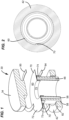
FIG. 1 is an exploded, perspective view of parts of an air oil separator assembly including a filter element, constructed in accordance with principles of this disclosure; -
FIG. 2 is a cross-sectional view of the assembly ofFIG. 1 ; -
FIG. 3 is an exploded perspective view of another embodiment of an air oil separator assembly including a filter element, constructed in accordance with principles of this disclosure; -
FIG. 4 is a cross-sectional view of a portion of the assembly ofFIG. 3 - None of the following
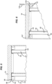
figures 5 to 23 are part of the invention.FIG. 5 is a cross-sectional view of another aspect of an air oil separator assembly; -
FIG. 6 is another cross-sectional view of the air oil separator assembly ofFIG. 5 ; -
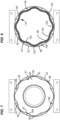
FIG. 7 is a top plan view of the air oil separator assembly ofFIGS. 5 and 6 with the cover removed; -
FIG. 8 is a top plan view of the air oil separator assembly ofFIGS. 5-7 , with the cover and the filter element removed; -
FIG. 9 is a portion of a top plan view of the assembly, similar toFIG. 7 , but showing a variation; -
FIG. 10 is a top plan view, similar toFIG. 8 , but showing a variation; -
FIG. 11 is a perspective view of a portion of the tank usable in the air oil separator assembly ofFIGS. 5 and 6 ; -
FIG. 12 is a perspective view of a portion of the assembly ofFIGS. 5 and 6 and showing the filter element installed in the tank; -
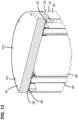
FIG. 13 is a perspective view of a cross section of the air oil separator assembly ofFIGS. 5 and 6 ; -
FIG. 14 is a top plan view of the air oil separator assembly ofFIGS. 5 and 6 ; -
FIG. 15 is a cross-sectional view of the assembly, with the cross section being taken along the line A-A ofFIG. 14 ; -
FIG. 16 is a cross-sectional view of the assembly ofFIGS. 5 and 6 , with the cross section being taken along the line B-B ofFIG. 14 ; -
FIG. 17 is a top plan view of the air oil separator assembly with the cover removed; -
FIG. 18 is a top plan view of the air oil separator assembly with both the cover and the element removed; -
FIG. 19 is an exploded, perspective view of the air oil separator assembly ofFIGS. 5 and 6 showing the tank, filter element, and cover; -
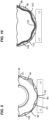
FIG. 20 is a cross-sectional view of an air oil separator assembly, showing the tank, filter element, and cover; -
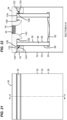
FIG. 21 is a front, elevational view of a portion of the air oil separator assembly ofFIG. 20 ; -
FIG. 22 is a cross-sectional view of the air oil separator assembly ofFIGS. 20 and21 , the cross section being taken along the line A-A ofFIG. 21 ; and -
FIG. 23 is a schematic, cross-sectional view of a portion of the air oil separator assembly ofFIGS. 20-22 . - Turning first to
FIG. 20 , an example embodiment, which is not part of the invention, of an air oil separator assembly is shown generally at 30. Theassembly 30 includes a vessel ortank 32. Thetank 32 includes ahousing 33 and acover 34. - The
housing 33 has a surroundingwall 35 that defines aninterior volume 36. Thehousing 33 has a closedbottom 37 and anopen mouth 38 in communication with theinterior volume 36. - The
tank 32 further includes aninlet 40 extending through thewall 35. Theinlet 40 takes in an oil-entrained air stream into theinterior volume 36. - A lower
liquid sump 41 is in theinterior volume 36 and held by the closedbottom 37. Theliquid sump 41 is typically coalesced oil that is has been removed from the air stream being brought into theassembly 30. - The
tank 32 further includes aflange 42. Theflange 42 circumscribes themouth 38. - The
cover 34 is removably mounted on thetank 32 and over themouth 38 to provided selective access to theinterior volume 36. InFIG. 20 , thecover 34 is positionable on theflange 42. In theFIG. 20 aspect, thecover 34 has anopening 44. The opening 44 can be anair flow outlet 45. In other aspects, thecover 34 has no openings (e.g., is closed), and the air flow outlet is in a different part of the airoil separator assembly 30. - Positioned within the
interior volume 36 of thetank 32 is a removable andreplaceable filter element 46. Thefilter element 46 will separate gas from liquid (e.g. air from oil) that is being brought into thetank 32 through theinlet 40. The air and oil inlet stream flows into theinlet 40 and into theinterior volume 36. From there, it passes through thefilter element 46. Thefilter element 46 separates the air from the oil, and coalesces the oil causing it to drain to the bottom of thetank 32 and be collected in thesump 41. The air that has had the oil removed then exits thetank 32 through theoutlet 45. - In general, the
filter element 46 includes a tubular construction offilter media 48. Thefilter media 48 can often be a pleated media formed in a cylinder. In the interior of the tubular construction ofmedia 48 is afilter interior 50, which is typically a clean air volume. - The
filter media 48 has opposite first and second ends 51, 52. Thefilter element 50 further has alongitudinal axis 54 extending along the length thereof. In the example shown inFIG. 20 , thelongitudinal axis 54 passes through a center of thefilter interior 50 and is perpendicular to a plane containing thefirst end 51 and perpendicular to a plane containing thesecond end 52. - The
filter media 48, as mentioned previously, is typically a type of filter media that will separate oil from a gas stream. Thefilter media 46 can be embodied as a media configuration, having multiple layered media grades and types. - The filter media will typically cause the oil within the gas stream to coalesce, which will then form droplets and drip by gravity into the
sump 41. Themedia 48 can be a pleated media, but can include non-pleated as well. When pleated media is use, a direction of the pleats extend parallel to thelongitudinal axis 54 in a direction between the first and second ends 51, 52. In this example, the flow through thefilter element 46 is from the outside, through themedia 48 and then into thefilter interior 50. From thefilter interior 50, it exits theassembly 30 through theoutlet 45. Other arrangements can include the flow through theelement 46 from the inside to the outside. - The
filter media 48 will often be supported by at least aninner liner 56. Theinner liner 56 will help prevent the collapse of the pleats of themedia 48. Thefilter element 46 can further include anouter liner 58. Theouter liner 58 is along an outer diameter of thepleated media 48 and extends between the first and second ends 51, 52. - In many examples, the
filter element 46 further includes a firstend cap construction 60. The firstend cap construction 60 is secured tofirst end 51 of themedia 48. Often, secured to asecond end 52 of themedia 48 is asecond end cap 62. In the example shown, thesecond end cap 62 is a closed end cap. - Various aspects of variations on the
assembly 30 are now described below. Common features will includes the same reference numeral, and will not be defined again. - Turning now to the embodiment of
FIGS. 1-4 , thefilter element 46 includes the firstend cap construction 60 as defining a flange-receiving recess therein. - The first
end cap construction 60, in this embodiment, includes anaxial plate 72 and anannular sleeve 73. Theannular sleeve 73 extends perpendicular from theplate 72 in a direction toward thefilter media 48. Theannular sleeve 73 includes an outerradial ring 74 adjacent to theouter liner 58 and an innerradial ring 75 adjacent to and radially inward of theinner liner 56. - As can be seen in
FIGS. 1 and3 , thefilter media 48 is located between the outerradial ring 74 and the innerradial ring 75. - In the embodiment of
FIGS. 1 and 2 , therecess 70 is defined by theannular sleeve 73. In the example shown, therecess 70 is a longitudinally extending recess generally parallel to thelongitudinal axis 54. Therecess 70 in the embodiment ofFIGS. 1 and 2 is defined by the outerradial ring 74. - In the embodiment of
FIGS. 3 and 4 , therecess 70 is defined by theaxial plate 72. In particular, theaxial plate 72 includes anupper surface 78 and an oppositelower surface 79. Thelower surface 79 faces thefilter media 48. Therecess 70 is a continuous ring in thelower surface 79 of theplate 72. Theupper surface 78 of theplate 72 can include anaxially extending rib 80 forming a continuous ring. - In the embodiment of
FIGS. 1-4 , therecess 70 can include a variety of cross section including, for example, rounded, polygon, trapezoidal, curved, or irregular. - The
filter element 46 of the embodiments shown inFIGS. 1-4 can be removably positioned in theinterior volume 36 of thetank 32 of anair oil assembly 30. In theair oil assembly 30, theflange 42 of thetank 32 include aprojection 82. Theprojection 82 on theflange 42 extends into the flange-receivingrecess 70 of the firstend cap construction 60 of thefilter element 46. - The air
oil separator assembly 30 further includes afirst seal member 84 between and against theflange 42 and the firstend cap construction 60. Thefirst seal member 84 can include, for example, a gasket or an O-ring. Asecond seal member 85 is between and against the firstend cap construction 60 and thecover 34. Thesecond seal member 85 can be in the form of a gasket or O-ring seal member. - In the embodiment of
FIGS. 1 and 2 , theprojection 82 on theflange 42 extends radially inwardly from theflange 42 and extends radially inwardly into theopen mouth 38 of thetank 32. Theprojection 42 is received by therecess 70 in the outerradial ring 74 of thesleeve 73. - In the embodiment of
FIGS. 3 and 4 , theprojection 82 on theflange 42 extends axially upwardly into therecess 70, which is in the form of continuous ring in thelower surface 79 of theplate 72. - In the embodiment of
FIGS. 3 and 4 , thecover 34 further includes acontinuous recess 86 in the portion of thecover 34 that engages against theflange 42 of thetank 32. Therecess 86 in thecover 34 receives therib 80 of theupper surface 78 of theplate 72. - It should be understood that the
projection 82 on theflange 42 can have a cross section of many different shapes including, for example, rounded, polygon, trapezoidal, curved, or irregular. - Turning now to the embodiment, which is not part of the invention, of
FIGS. 5-19 , another example ofair oil assembly 30 havingtank 32 andfilter element 46 is shown. In this aspect, thefilter element 46 has at its first end cap construction 60 a plurality of alternating radiallyoutward projections 90 and radially inward recesses 91. In the example aspect shown, the alternatingprojections 90 and recesses 91 are along a radiallyoutward periphery 92 of theaxial plate 72 of the firstend cap construction 60. - While many aspects are possible, in the one shown, the
projections 90 and recesses 91 are curved surfaces. Theprojections 90 and recesses 91 give the appearance of a wave. - Attention is directed to
FIG. 9 . InFIG. 9 , there is at least one of the projections that extends radially outwardly more than a majority of remainder of theprojections 90. In the example shown, only asingle projection 94 extends radially outwardly more than all of a remainder of theprojections 90. Thisprojection 94 helps to perform a handle or grasping member to allow thefilter element 46 to be more easily removed from thetank 32. - In reference now to
FIGS. 5, 6 , and11-13 , theflange 42 of thetank 32 has a lid-engagingsection 96 and anelement engaging section 98. Theelement engaging section 98 is axially recessed from and radially inward of thelid engaging section 96. Theelement engaging section 98 has agroove 100 holding aseal member 101 therein. Each of thelid engaging section 96 andelement engaging section 98 has a plurality of alternating radiallyinward protrusions 102 and radially outward depressions 103. - The filter element of the assembly of
FIGS. 5-19 is removably positioned in theinterior volume 36 of thetank 32 with a portion of the firstend cap construction 60 axially against theseal member 101 in theelement engaging section 98 of thetank flange 42 and is circumscribed by thelid engaging section 96. The radiallyoutward projections 90 of the firstend cap construction 60 are received by thedepressions 103 of thelid engaging section 96. The radially inward recesses 91 of the firstend cap construction 60 receive theprotrusions 102 of thelid engaging section 96. - As can be seen in
FIGS. 6-8 , thelid engaging section 96 of theflange 42 includes a plurality offastener holes 106 in an axial section thereof. Thecover 34 includesholes 107 that receive axially extending fasteners, such asbolts 108 removably mounted in the fastener holes 106, 107 to allow thecover 34 to be removably fastened to thetank 32. - As can be seen in
FIG. 8 , thegroove 100 andseal member 101 form awavy ring 110. - In
FIG. 10 , in the aspect that has theprojection 94 extending radially outwardly more than a remainder of theprojections 90, the lid-engagingsection 96 can have asection 112 that is machined through to allow the protrudingprojection 94 to extend radially beyond or outside an outer diameter of thewall 35 of thetank 32. - Turning now to the embodiment of
FIGS. 20-23 , which is not part of the invention, the firstend cap construction 60, in this aspect, includes an outerradial portion 120 including acontinuous extension 121 extending radially outwardly from the outer diameter of thefilter medial 48. Thecontinuous extension 121 has afirst section 122 defining anouter periphery 123 of theextension 121. Thecontinuous extension 121 further includes asecond section 124 between thefirst section 122 and the outer diameter of thefilter media 48. - The
first section 122 is contained within a plane that is perpendicular to thelongitudinal axis 54. Thesecond section 124 slopes from thefirst section 92 in a direction toward thesecond end 52 of thefilter media 48. - The first
end cap construction 60 further includes a centeringring 126. The centeringring 126 is radially inward from the inner diameter of thefilter media 48. Thecentral ring 126 defines anopening 128 in communication with the interior 50 of the tubular construction offilter media 48. The centering ring 146 helps to center thecover 34 over theelement 46 andtank wall 35. - The
flange 42, in this aspect, has a first radiallyoutward surface 130 and a frusto-conical surface 132. The frusto-conical surface 132 is between thefirst surface 130 and the inner diameter of theflange 42. - The
filter element 46 is positioned in theinterior volume 36 with thefirst section 122 of the firstend cap construction 60 being against thefirst surface 130 of theflange 42. Thesecond section 124 is received by the frusto-conical surface 132 of theflange 42. - The
cover 34 is removably mounted on thetank 32 over themouth 38 to provide selective access to theinterior volume 36. Thecover 34 has anelement engaging side 134 with anaxial protrusion 136 extending into and being received by thesecond section 124 of the firstend cap construction 60. - The air
oil separator assembly 30 further includes afirst seal member 138, which can be an O-ring, between thesecond section 124 of the firstend cap construction 60 and thecover 34. Asecond seal member 140 can be between thesecond section 124 of the firstend cap construction 60 and theflange 42. In particular, thesecond seal member 140 can be against the frusto-conical section 132 of theflange 42. - In some alternate aspects, the first
end cap construction 60 can have the centeringring 126 extend further radially inwardly such that it provides all, or at least a portion, of anoutlet flow surface 142 of theoutlet 45. In the example shown, theoutlet flow surface 142 is a curved surface of thecover 34, but in the alternate aspect, theend cap construction 60 itself would form the curved surface of theoutlet 45 and lead to theopening 44 in thecover 34.
Claims (7)
- An air oil separator assembly (30) comprising:(a) a tank (32) with a surrounding wall (35) defining an interior volume (36) (36), an open mouth in communication with the interior volume (36), and a closed bottom (37); the tank (32) further including,(i) an inlet (40) extending through the wall (35);(ii) a lower liquid sump (41) in the interior volume (36) held by the closed bottom (37); and(iii) a flange (42) circumscribing the mouth; the flange (42) having a projection (82) therefrom; and(b) a filter element (46) removably positioned in the interior volume (36); the filter element (46) comprising:(i) a tubular construction of filter media (48) having opposite first and second ends (51, 52) and a longitudinal axis; and(ii) a first end cap construction (60) secured to the first end (51) of the filter media (48); the first end cap construction (60) including a flange-receiving recess (70) therein;wherein the projection (82) on the flange (42) of the tank (32) extends into the flange-receiving recess (70) of the first end cap construction (60);characterized in that said air oil separator assembly (30) further comprises a cover (34) removably mounted on the tank (32) over the mouth to provide selective access to the interior volume (36).
- The air oil separator assembly (30) of claim 1 further comprising:(a) a first seal member (84) between and against the flange (42) of the tank (32) and the first end cap construction (60); and(b) a second seal member (85) between and against the first end cap construction (60) and the cover (34).
- The air oil separator assembly (30) of any of the previous claims wherein:(a) the first end cap construction (60) includes an axial plate (72) and an annular sleeve extending perpendicular from the plate (72) in a direction toward the filter media (48); the annular sleeve (73) having an outer radial ring (74) and an inner radial ring (75); the filter media (48) being between the outer radial ring (74) and the inner radial ring (75); and the recess (70) is a longitudinally extending recess parallel to the longitudinal axis (54) and is defined by the outer radial ring (74); and(b) the projection (82) on the flange (42) extends radially inwardly into the mouth (38).
- The air oil separator assembly (30) of any one of claims 1 and 2 wherein:(a) the first end cap construction (60) includes an axial plate (72) and an annular sleeve (73) extending perpendicular from the plate (72) in a direction toward the filter media (48); the annular sleeve (73) having an outer radial ring (74) and an inner radial ring (75); the filter media (48) being between the outer radial ring (74) and the inner radial ring (75); the axial plate (72) has an upper surface (78) and an opposite lower surface (79), the lower surface (79) facing the filter media (48); the recess (70) is a continuous ring in the lower surface of the plate (72); and(b) the projection (82) on the flange (42) extends axially upwardly into the continuous ring of the recess (70).
- The air oil separator assembly (30) of claim 4 wherein:(a) the upper surface of the plate (72) includes an axially extending rib (80) forming a continuous ring; and(b) the cover (34) includes a continuous recess receiving the rib (80) of the upper surface (78) of the plate (72).
- The air oil separator assembly (30) of any of the previous claims wherein the projection (82) on the flange (42) has a cross-section with a shape of any one of: rounded, polygon, trapezoidal, curved, or irregular.
- The air oil separator assembly (30) of any of the previous claims, wherein the recess (70) has a cross-section with a shape of any one of: rounded, polygon, trapezoidal, curved, or irregular.
Applications Claiming Priority (2)
| Application Number | Priority Date | Filing Date | Title |
|---|---|---|---|
| US201962850304P | 2019-05-20 | 2019-05-20 | |
| PCT/US2020/033440 WO2020236737A1 (en) | 2019-05-20 | 2020-05-18 | Air oil separator |
Publications (2)
| Publication Number | Publication Date |
|---|---|
| EP3972715A1 EP3972715A1 (en) | 2022-03-30 |
| EP3972715B1 true EP3972715B1 (en) | 2024-04-10 |
Family
ID=71069979
Family Applications (1)
| Application Number | Title | Priority Date | Filing Date |
|---|---|---|---|
| EP20731672.0A Active EP3972715B1 (en) | 2019-05-20 | 2020-05-18 | Air oil separator |
Country Status (5)
| Country | Link |
|---|---|
| US (1) | US12280328B2 (en) |
| EP (1) | EP3972715B1 (en) |
| JP (1) | JP7724714B2 (en) |
| CN (1) | CN114270036A (en) |
| WO (1) | WO2020236737A1 (en) |
Families Citing this family (3)
| Publication number | Priority date | Publication date | Assignee | Title |
|---|---|---|---|---|
| CN113623177A (en) * | 2021-09-23 | 2021-11-09 | 杨广林 | Horizontal compressor with oil-gas separation mechanism |
| EP4650029B1 (en) | 2024-05-17 | 2026-01-28 | Donaldson Company, Inc. | Filter elements and assemblies |
| US12434181B1 (en) | 2024-11-01 | 2025-10-07 | Donaldson Company, Inc. | Air cleaner and filtration assemblies |
Family Cites Families (28)
| Publication number | Priority date | Publication date | Assignee | Title |
|---|---|---|---|---|
| JPS60151517U (en) * | 1984-03-16 | 1985-10-08 | 日本ドナルドソン株式会社 | Filter for air/oil separator |
| BE1011715A3 (en) * | 1998-01-20 | 1999-12-07 | Atlas Copco Airpower Nv | Liquid separator AND FILTER ELEMENT THEREFOR. |
| JP2000177764A (en) * | 1998-10-06 | 2000-06-27 | Kitahara Sangyo:Kk | Hermetically sealed container |
| US6093231A (en) * | 1998-10-16 | 2000-07-25 | Air-Maze Corporation | Air/oil separator with unitary top end cap and flange |
| EP1322399B1 (en) * | 2000-08-11 | 2011-07-13 | Omnipure Filter Company, Inc. | Keyed system for connection of filter cartridge to filter holder |
| JP2002166118A (en) * | 2000-12-01 | 2002-06-11 | Toyo Element Industry Co Ltd | Air filter element and method for manufacturing the same |
| US20040035094A1 (en) * | 2002-04-10 | 2004-02-26 | Jersey Ray De | Diesel engine exhaust filter |
| DE10224224A1 (en) * | 2002-05-31 | 2003-12-11 | Mann & Hummel Filter | Filter element, in particular for filtering liquids |
| US20060086656A1 (en) | 2004-10-25 | 2006-04-27 | Morgan H W | Fluid filter with modular housing and method of manufacture |
| DE202006002383U1 (en) | 2005-02-28 | 2006-07-13 | Mann + Hummel Gmbh | Filter element for separating liquid from gas stream, comprises annularly closed filter medium, upper end disk, and lower end disk with drainage tube |
| US7524349B2 (en) * | 2005-05-03 | 2009-04-28 | Donaldson Company, Inc. | Air cleaner; air filter cartridge and method of manufacturing |
| GB0715269D0 (en) * | 2007-08-04 | 2007-09-12 | Parker Hannifin Ltd | Filter assembly |
| US8167966B2 (en) * | 2008-04-07 | 2012-05-01 | Cummins Filtration Ip, Inc. | Replaceable filter cartridge with removal feature |
| USD638034S1 (en) | 2009-03-11 | 2011-05-17 | Cummins Filtration Ip, Inc. | Engine filter |
| DE102011110498A1 (en) | 2011-08-17 | 2013-02-21 | Mann + Hummel Gmbh | filter |
| CN103987928B (en) * | 2011-10-20 | 2017-07-21 | 唐纳森公司 | Air/oil separators component, part and method |
| WO2013063497A2 (en) | 2011-10-26 | 2013-05-02 | Donaldson Company, Inc | Filter assemblies; components and features thereof: and, methods of use and assembly |
| US9387425B2 (en) * | 2011-10-26 | 2016-07-12 | Donaldson Company, Inc. | Filter assemblies; components and features thereof; and, methods of use and assembly |
| TR201902974T4 (en) * | 2013-02-04 | 2019-03-21 | Mann & Hummel Gmbh | Cup-shaped housing and device for separating liquid from air. |
| DE102014002719B4 (en) | 2013-05-15 | 2017-10-12 | Mann + Hummel Gmbh | Separator element and liquid separator for separating liquids from a gas stream |
| EP3265206B1 (en) * | 2015-03-03 | 2021-09-22 | MANN+HUMMEL GmbH | Filter element and method for manufacturing a filter element |
| DE102016005357A1 (en) * | 2015-06-01 | 2016-12-01 | Mann+Hummel Gmbh | Filter element, oil separator and method of controlling the pressure prevailing in a crankcase [housing] ventilation system |
| US10625184B2 (en) | 2015-11-03 | 2020-04-21 | MANN+HUMMEL Filtration Technology Group Inc. | Coalescing filter element |
| DE102017003489A1 (en) * | 2017-04-11 | 2018-10-11 | Rt-Filtertechnik Gmbh | filter means |
| DE112018003692T5 (en) * | 2017-07-20 | 2020-04-02 | Cummins Filtration Ip, Inc. | AIR FILTER WITH RADIAL SEAL |
| DE102018123413B4 (en) | 2017-10-06 | 2024-12-12 | Mann+Hummel Gmbh | Filter insert and device for separating oil aerosol from air |
| DE112018006269T5 (en) * | 2017-12-08 | 2020-08-20 | Cummins Filtration Ip, Inc. | Oval seal with stabilizing contour |
| CN112020387A (en) * | 2018-01-24 | 2020-12-01 | 唐纳森公司 | Filter element, system, and method |
-
2020
- 2020-05-18 WO PCT/US2020/033440 patent/WO2020236737A1/en not_active Ceased
- 2020-05-18 US US17/613,438 patent/US12280328B2/en active Active
- 2020-05-18 JP JP2021560739A patent/JP7724714B2/en active Active
- 2020-05-18 EP EP20731672.0A patent/EP3972715B1/en active Active
- 2020-05-18 CN CN202080035911.1A patent/CN114270036A/en active Pending
Also Published As
| Publication number | Publication date |
|---|---|
| US20220305421A1 (en) | 2022-09-29 |
| JP2022533903A (en) | 2022-07-27 |
| WO2020236737A1 (en) | 2020-11-26 |
| US12280328B2 (en) | 2025-04-22 |
| JP7724714B2 (en) | 2025-08-18 |
| CN114270036A (en) | 2022-04-01 |
| EP3972715A1 (en) | 2022-03-30 |
Similar Documents
| Publication | Publication Date | Title |
|---|---|---|
| US11471803B2 (en) | Fuel water separator filter with an improved sealing arrangement | |
| US8177971B2 (en) | Filter assembly | |
| EP2192964B1 (en) | Filter cartridge housing attachment system | |
| US10343096B2 (en) | Filter elements, coalescing baffles, filtration vessel and methods | |
| CA3015979C (en) | Liquid filter arrangement and methods | |
| EP1694424B1 (en) | Separator arrangement for gas/liquid separation; apparatus; and, methods | |
| US7857974B2 (en) | Filter cartridge with snap fit connection | |
| EP4122576B1 (en) | Filtration system with housing and filter element | |
| EP2178619B1 (en) | Filter assembly | |
| EP0732135B1 (en) | Liquid filter | |
| US20170120168A1 (en) | Coalescing Filter Element | |
| US7749383B2 (en) | Filter cartridge with crush ribs | |
| US12280328B2 (en) | Air oil separator | |
| US20260091337A1 (en) | Gas filter separator filter cartridge with keys and/or baffle | |
| US11117077B2 (en) | Filter assembly | |
| US11400392B2 (en) | Filter element | |
| EP3200895A2 (en) | Filter media support core | |
| WO2018140310A1 (en) | Expandable threaded adapter for threadless shell | |
| EP3570955B1 (en) | A filter assembly | |
| CA3076654A1 (en) | Filter elements, coalescing baffles, filtration vessel and methods | |
| EP4628186A1 (en) | Valve arrangement for a filtration system | |
| EP4506050A1 (en) | Composite structure for liquid filtration device |
Legal Events
| Date | Code | Title | Description |
|---|---|---|---|
| STAA | Information on the status of an ep patent application or granted ep patent |
Free format text: STATUS: UNKNOWN |
|
| STAA | Information on the status of an ep patent application or granted ep patent |
Free format text: STATUS: THE INTERNATIONAL PUBLICATION HAS BEEN MADE |
|
| PUAI | Public reference made under article 153(3) epc to a published international application that has entered the european phase |
Free format text: ORIGINAL CODE: 0009012 |
|
| STAA | Information on the status of an ep patent application or granted ep patent |
Free format text: STATUS: REQUEST FOR EXAMINATION WAS MADE |
|
| 17P | Request for examination filed |
Effective date: 20211119 |
|
| AK | Designated contracting states |
Kind code of ref document: A1 Designated state(s): AL AT BE BG CH CY CZ DE DK EE ES FI FR GB GR HR HU IE IS IT LI LT LU LV MC MK MT NL NO PL PT RO RS SE SI SK SM TR |
|
| DAV | Request for validation of the european patent (deleted) | ||
| DAX | Request for extension of the european patent (deleted) | ||
| RAP3 | Party data changed (applicant data changed or rights of an application transferred) |
Owner name: DONALDSON COMPANY, INC. |
|
| GRAP | Despatch of communication of intention to grant a patent |
Free format text: ORIGINAL CODE: EPIDOSNIGR1 |
|
| STAA | Information on the status of an ep patent application or granted ep patent |
Free format text: STATUS: GRANT OF PATENT IS INTENDED |
|
| INTG | Intention to grant announced |
Effective date: 20231027 |
|
| GRAS | Grant fee paid |
Free format text: ORIGINAL CODE: EPIDOSNIGR3 |
|
| GRAA | (expected) grant |
Free format text: ORIGINAL CODE: 0009210 |
|
| STAA | Information on the status of an ep patent application or granted ep patent |
Free format text: STATUS: THE PATENT HAS BEEN GRANTED |
|
| AK | Designated contracting states |
Kind code of ref document: B1 Designated state(s): AL AT BE BG CH CY CZ DE DK EE ES FI FR GB GR HR HU IE IS IT LI LT LU LV MC MK MT NL NO PL PT RO RS SE SI SK SM TR |
|
| REG | Reference to a national code |
Ref country code: GB Ref legal event code: FG4D |
|
| REG | Reference to a national code |
Ref country code: CH Ref legal event code: EP |
|
| REG | Reference to a national code |
Ref country code: DE Ref legal event code: R096 Ref document number: 602020028769 Country of ref document: DE |
|
| REG | Reference to a national code |
Ref country code: IE Ref legal event code: FG4D |
|
| P01 | Opt-out of the competence of the unified patent court (upc) registered |
Effective date: 20240426 |
|
| REG | Reference to a national code |
Ref country code: LT Ref legal event code: MG9D |
|
| REG | Reference to a national code |
Ref country code: NL Ref legal event code: MP Effective date: 20240410 |
|
| REG | Reference to a national code |
Ref country code: AT Ref legal event code: MK05 Ref document number: 1674350 Country of ref document: AT Kind code of ref document: T Effective date: 20240410 |
|
| PG25 | Lapsed in a contracting state [announced via postgrant information from national office to epo] |
Ref country code: NL Free format text: LAPSE BECAUSE OF FAILURE TO SUBMIT A TRANSLATION OF THE DESCRIPTION OR TO PAY THE FEE WITHIN THE PRESCRIBED TIME-LIMIT Effective date: 20240410 |
|
| PG25 | Lapsed in a contracting state [announced via postgrant information from national office to epo] |
Ref country code: NL Free format text: LAPSE BECAUSE OF FAILURE TO SUBMIT A TRANSLATION OF THE DESCRIPTION OR TO PAY THE FEE WITHIN THE PRESCRIBED TIME-LIMIT Effective date: 20240410 |
|
| PG25 | Lapsed in a contracting state [announced via postgrant information from national office to epo] |
Ref country code: IS Free format text: LAPSE BECAUSE OF FAILURE TO SUBMIT A TRANSLATION OF THE DESCRIPTION OR TO PAY THE FEE WITHIN THE PRESCRIBED TIME-LIMIT Effective date: 20240810 |
|
| PG25 | Lapsed in a contracting state [announced via postgrant information from national office to epo] |
Ref country code: BG Free format text: LAPSE BECAUSE OF FAILURE TO SUBMIT A TRANSLATION OF THE DESCRIPTION OR TO PAY THE FEE WITHIN THE PRESCRIBED TIME-LIMIT Effective date: 20240410 |
|
| PG25 | Lapsed in a contracting state [announced via postgrant information from national office to epo] |
Ref country code: FI Free format text: LAPSE BECAUSE OF FAILURE TO SUBMIT A TRANSLATION OF THE DESCRIPTION OR TO PAY THE FEE WITHIN THE PRESCRIBED TIME-LIMIT Effective date: 20240410 Ref country code: HR Free format text: LAPSE BECAUSE OF FAILURE TO SUBMIT A TRANSLATION OF THE DESCRIPTION OR TO PAY THE FEE WITHIN THE PRESCRIBED TIME-LIMIT Effective date: 20240410 |
|
| PG25 | Lapsed in a contracting state [announced via postgrant information from national office to epo] |
Ref country code: GR Free format text: LAPSE BECAUSE OF FAILURE TO SUBMIT A TRANSLATION OF THE DESCRIPTION OR TO PAY THE FEE WITHIN THE PRESCRIBED TIME-LIMIT Effective date: 20240711 |
|
| PG25 | Lapsed in a contracting state [announced via postgrant information from national office to epo] |
Ref country code: PT Free format text: LAPSE BECAUSE OF FAILURE TO SUBMIT A TRANSLATION OF THE DESCRIPTION OR TO PAY THE FEE WITHIN THE PRESCRIBED TIME-LIMIT Effective date: 20240812 |
|
| PG25 | Lapsed in a contracting state [announced via postgrant information from national office to epo] |
Ref country code: ES Free format text: LAPSE BECAUSE OF FAILURE TO SUBMIT A TRANSLATION OF THE DESCRIPTION OR TO PAY THE FEE WITHIN THE PRESCRIBED TIME-LIMIT Effective date: 20240410 |
|
| PG25 | Lapsed in a contracting state [announced via postgrant information from national office to epo] |
Ref country code: AT Free format text: LAPSE BECAUSE OF FAILURE TO SUBMIT A TRANSLATION OF THE DESCRIPTION OR TO PAY THE FEE WITHIN THE PRESCRIBED TIME-LIMIT Effective date: 20240410 |
|
| PG25 | Lapsed in a contracting state [announced via postgrant information from national office to epo] |
Ref country code: PL Free format text: LAPSE BECAUSE OF FAILURE TO SUBMIT A TRANSLATION OF THE DESCRIPTION OR TO PAY THE FEE WITHIN THE PRESCRIBED TIME-LIMIT Effective date: 20240410 |
|
| PG25 | Lapsed in a contracting state [announced via postgrant information from national office to epo] |
Ref country code: LV Free format text: LAPSE BECAUSE OF FAILURE TO SUBMIT A TRANSLATION OF THE DESCRIPTION OR TO PAY THE FEE WITHIN THE PRESCRIBED TIME-LIMIT Effective date: 20240410 |
|
| PG25 | Lapsed in a contracting state [announced via postgrant information from national office to epo] |
Ref country code: PT Free format text: LAPSE BECAUSE OF FAILURE TO SUBMIT A TRANSLATION OF THE DESCRIPTION OR TO PAY THE FEE WITHIN THE PRESCRIBED TIME-LIMIT Effective date: 20240812 Ref country code: PL Free format text: LAPSE BECAUSE OF FAILURE TO SUBMIT A TRANSLATION OF THE DESCRIPTION OR TO PAY THE FEE WITHIN THE PRESCRIBED TIME-LIMIT Effective date: 20240410 Ref country code: NO Free format text: LAPSE BECAUSE OF FAILURE TO SUBMIT A TRANSLATION OF THE DESCRIPTION OR TO PAY THE FEE WITHIN THE PRESCRIBED TIME-LIMIT Effective date: 20240710 Ref country code: LV Free format text: LAPSE BECAUSE OF FAILURE TO SUBMIT A TRANSLATION OF THE DESCRIPTION OR TO PAY THE FEE WITHIN THE PRESCRIBED TIME-LIMIT Effective date: 20240410 Ref country code: IS Free format text: LAPSE BECAUSE OF FAILURE TO SUBMIT A TRANSLATION OF THE DESCRIPTION OR TO PAY THE FEE WITHIN THE PRESCRIBED TIME-LIMIT Effective date: 20240810 Ref country code: HR Free format text: LAPSE BECAUSE OF FAILURE TO SUBMIT A TRANSLATION OF THE DESCRIPTION OR TO PAY THE FEE WITHIN THE PRESCRIBED TIME-LIMIT Effective date: 20240410 Ref country code: GR Free format text: LAPSE BECAUSE OF FAILURE TO SUBMIT A TRANSLATION OF THE DESCRIPTION OR TO PAY THE FEE WITHIN THE PRESCRIBED TIME-LIMIT Effective date: 20240711 Ref country code: FI Free format text: LAPSE BECAUSE OF FAILURE TO SUBMIT A TRANSLATION OF THE DESCRIPTION OR TO PAY THE FEE WITHIN THE PRESCRIBED TIME-LIMIT Effective date: 20240410 Ref country code: ES Free format text: LAPSE BECAUSE OF FAILURE TO SUBMIT A TRANSLATION OF THE DESCRIPTION OR TO PAY THE FEE WITHIN THE PRESCRIBED TIME-LIMIT Effective date: 20240410 Ref country code: BG Free format text: LAPSE BECAUSE OF FAILURE TO SUBMIT A TRANSLATION OF THE DESCRIPTION OR TO PAY THE FEE WITHIN THE PRESCRIBED TIME-LIMIT Effective date: 20240410 Ref country code: AT Free format text: LAPSE BECAUSE OF FAILURE TO SUBMIT A TRANSLATION OF THE DESCRIPTION OR TO PAY THE FEE WITHIN THE PRESCRIBED TIME-LIMIT Effective date: 20240410 Ref country code: RS Free format text: LAPSE BECAUSE OF FAILURE TO SUBMIT A TRANSLATION OF THE DESCRIPTION OR TO PAY THE FEE WITHIN THE PRESCRIBED TIME-LIMIT Effective date: 20240710 |
|
| REG | Reference to a national code |
Ref country code: CH Ref legal event code: PL |
|
| REG | Reference to a national code |
Ref country code: DE Ref legal event code: R097 Ref document number: 602020028769 Country of ref document: DE |
|
| PG25 | Lapsed in a contracting state [announced via postgrant information from national office to epo] |
Ref country code: DK Free format text: LAPSE BECAUSE OF FAILURE TO SUBMIT A TRANSLATION OF THE DESCRIPTION OR TO PAY THE FEE WITHIN THE PRESCRIBED TIME-LIMIT Effective date: 20240410 |
|
| PG25 | Lapsed in a contracting state [announced via postgrant information from national office to epo] |
Ref country code: LU Free format text: LAPSE BECAUSE OF NON-PAYMENT OF DUE FEES Effective date: 20240518 |
|
| PG25 | Lapsed in a contracting state [announced via postgrant information from national office to epo] |
Ref country code: EE Free format text: LAPSE BECAUSE OF FAILURE TO SUBMIT A TRANSLATION OF THE DESCRIPTION OR TO PAY THE FEE WITHIN THE PRESCRIBED TIME-LIMIT Effective date: 20240410 |
|
| PG25 | Lapsed in a contracting state [announced via postgrant information from national office to epo] |
Ref country code: CZ Free format text: LAPSE BECAUSE OF FAILURE TO SUBMIT A TRANSLATION OF THE DESCRIPTION OR TO PAY THE FEE WITHIN THE PRESCRIBED TIME-LIMIT Effective date: 20240410 |
|
| PG25 | Lapsed in a contracting state [announced via postgrant information from national office to epo] |
Ref country code: SK Free format text: LAPSE BECAUSE OF FAILURE TO SUBMIT A TRANSLATION OF THE DESCRIPTION OR TO PAY THE FEE WITHIN THE PRESCRIBED TIME-LIMIT Effective date: 20240410 Ref country code: RO Free format text: LAPSE BECAUSE OF FAILURE TO SUBMIT A TRANSLATION OF THE DESCRIPTION OR TO PAY THE FEE WITHIN THE PRESCRIBED TIME-LIMIT Effective date: 20240410 |
|
| PG25 | Lapsed in a contracting state [announced via postgrant information from national office to epo] |
Ref country code: SM Free format text: LAPSE BECAUSE OF FAILURE TO SUBMIT A TRANSLATION OF THE DESCRIPTION OR TO PAY THE FEE WITHIN THE PRESCRIBED TIME-LIMIT Effective date: 20240410 |
|
| PG25 | Lapsed in a contracting state [announced via postgrant information from national office to epo] |
Ref country code: SM Free format text: LAPSE BECAUSE OF FAILURE TO SUBMIT A TRANSLATION OF THE DESCRIPTION OR TO PAY THE FEE WITHIN THE PRESCRIBED TIME-LIMIT Effective date: 20240410 Ref country code: SK Free format text: LAPSE BECAUSE OF FAILURE TO SUBMIT A TRANSLATION OF THE DESCRIPTION OR TO PAY THE FEE WITHIN THE PRESCRIBED TIME-LIMIT Effective date: 20240410 Ref country code: RO Free format text: LAPSE BECAUSE OF FAILURE TO SUBMIT A TRANSLATION OF THE DESCRIPTION OR TO PAY THE FEE WITHIN THE PRESCRIBED TIME-LIMIT Effective date: 20240410 Ref country code: LU Free format text: LAPSE BECAUSE OF NON-PAYMENT OF DUE FEES Effective date: 20240518 Ref country code: EE Free format text: LAPSE BECAUSE OF FAILURE TO SUBMIT A TRANSLATION OF THE DESCRIPTION OR TO PAY THE FEE WITHIN THE PRESCRIBED TIME-LIMIT Effective date: 20240410 Ref country code: DK Free format text: LAPSE BECAUSE OF FAILURE TO SUBMIT A TRANSLATION OF THE DESCRIPTION OR TO PAY THE FEE WITHIN THE PRESCRIBED TIME-LIMIT Effective date: 20240410 Ref country code: CZ Free format text: LAPSE BECAUSE OF FAILURE TO SUBMIT A TRANSLATION OF THE DESCRIPTION OR TO PAY THE FEE WITHIN THE PRESCRIBED TIME-LIMIT Effective date: 20240410 Ref country code: CH Free format text: LAPSE BECAUSE OF NON-PAYMENT OF DUE FEES Effective date: 20240531 Ref country code: MC Free format text: LAPSE BECAUSE OF FAILURE TO SUBMIT A TRANSLATION OF THE DESCRIPTION OR TO PAY THE FEE WITHIN THE PRESCRIBED TIME-LIMIT Effective date: 20240410 |
|
| PG25 | Lapsed in a contracting state [announced via postgrant information from national office to epo] |
Ref country code: IT Free format text: LAPSE BECAUSE OF FAILURE TO SUBMIT A TRANSLATION OF THE DESCRIPTION OR TO PAY THE FEE WITHIN THE PRESCRIBED TIME-LIMIT Effective date: 20240410 |
|
| PLBE | No opposition filed within time limit |
Free format text: ORIGINAL CODE: 0009261 |
|
| STAA | Information on the status of an ep patent application or granted ep patent |
Free format text: STATUS: NO OPPOSITION FILED WITHIN TIME LIMIT |
|
| REG | Reference to a national code |
Ref country code: BE Ref legal event code: MM Effective date: 20240531 |
|
| 26N | No opposition filed |
Effective date: 20250113 |
|
| PG25 | Lapsed in a contracting state [announced via postgrant information from national office to epo] |
Ref country code: IE Free format text: LAPSE BECAUSE OF NON-PAYMENT OF DUE FEES Effective date: 20240518 |
|
| PG25 | Lapsed in a contracting state [announced via postgrant information from national office to epo] |
Ref country code: SI Free format text: LAPSE BECAUSE OF FAILURE TO SUBMIT A TRANSLATION OF THE DESCRIPTION OR TO PAY THE FEE WITHIN THE PRESCRIBED TIME-LIMIT Effective date: 20240410 Ref country code: BE Free format text: LAPSE BECAUSE OF NON-PAYMENT OF DUE FEES Effective date: 20240531 |
|
| PGFP | Annual fee paid to national office [announced via postgrant information from national office to epo] |
Ref country code: DE Payment date: 20250423 Year of fee payment: 6 |
|
| PGFP | Annual fee paid to national office [announced via postgrant information from national office to epo] |
Ref country code: GB Payment date: 20250423 Year of fee payment: 6 |
|
| PGFP | Annual fee paid to national office [announced via postgrant information from national office to epo] |
Ref country code: FR Payment date: 20250424 Year of fee payment: 6 |
|
| PG25 | Lapsed in a contracting state [announced via postgrant information from national office to epo] |
Ref country code: CY Free format text: LAPSE BECAUSE OF FAILURE TO SUBMIT A TRANSLATION OF THE DESCRIPTION OR TO PAY THE FEE WITHIN THE PRESCRIBED TIME-LIMIT; INVALID AB INITIO Effective date: 20200518 |
|
| PG25 | Lapsed in a contracting state [announced via postgrant information from national office to epo] |
Ref country code: HU Free format text: LAPSE BECAUSE OF FAILURE TO SUBMIT A TRANSLATION OF THE DESCRIPTION OR TO PAY THE FEE WITHIN THE PRESCRIBED TIME-LIMIT; INVALID AB INITIO Effective date: 20200518 |
|
| PG25 | Lapsed in a contracting state [announced via postgrant information from national office to epo] |
Ref country code: SE Free format text: LAPSE BECAUSE OF FAILURE TO SUBMIT A TRANSLATION OF THE DESCRIPTION OR TO PAY THE FEE WITHIN THE PRESCRIBED TIME-LIMIT Effective date: 20240410 |