EP3972258A1 - Information processing method and device, apparatus, and storage medium - Google Patents
Information processing method and device, apparatus, and storage medium Download PDFInfo
- Publication number
- EP3972258A1 EP3972258A1 EP19935729.4A EP19935729A EP3972258A1 EP 3972258 A1 EP3972258 A1 EP 3972258A1 EP 19935729 A EP19935729 A EP 19935729A EP 3972258 A1 EP3972258 A1 EP 3972258A1
- Authority
- EP
- European Patent Office
- Prior art keywords
- prediction
- prediction mode
- block
- mode
- coding block
- Prior art date
- Legal status (The legal status is an assumption and is not a legal conclusion. Google has not performed a legal analysis and makes no representation as to the accuracy of the status listed.)
- Granted
Links
Images






Classifications
-
- H—ELECTRICITY
- H04—ELECTRIC COMMUNICATION TECHNIQUE
- H04N—PICTORIAL COMMUNICATION, e.g. TELEVISION
- H04N19/00—Methods or arrangements for coding, decoding, compressing or decompressing digital video signals
- H04N19/60—Methods or arrangements for coding, decoding, compressing or decompressing digital video signals using transform coding
- H04N19/61—Methods or arrangements for coding, decoding, compressing or decompressing digital video signals using transform coding in combination with predictive coding
-
- H—ELECTRICITY
- H04—ELECTRIC COMMUNICATION TECHNIQUE
- H04N—PICTORIAL COMMUNICATION, e.g. TELEVISION
- H04N19/00—Methods or arrangements for coding, decoding, compressing or decompressing digital video signals
- H04N19/10—Methods or arrangements for coding, decoding, compressing or decompressing digital video signals using adaptive coding
- H04N19/102—Methods or arrangements for coding, decoding, compressing or decompressing digital video signals using adaptive coding characterised by the element, parameter or selection affected or controlled by the adaptive coding
- H04N19/103—Selection of coding mode or of prediction mode
- H04N19/105—Selection of the reference unit for prediction within a chosen coding or prediction mode, e.g. adaptive choice of position and number of pixels used for prediction
-
- H—ELECTRICITY
- H04—ELECTRIC COMMUNICATION TECHNIQUE
- H04N—PICTORIAL COMMUNICATION, e.g. TELEVISION
- H04N19/00—Methods or arrangements for coding, decoding, compressing or decompressing digital video signals
- H04N19/10—Methods or arrangements for coding, decoding, compressing or decompressing digital video signals using adaptive coding
- H04N19/102—Methods or arrangements for coding, decoding, compressing or decompressing digital video signals using adaptive coding characterised by the element, parameter or selection affected or controlled by the adaptive coding
- H04N19/103—Selection of coding mode or of prediction mode
- H04N19/11—Selection of coding mode or of prediction mode among a plurality of spatial predictive coding modes
-
- H—ELECTRICITY
- H04—ELECTRIC COMMUNICATION TECHNIQUE
- H04N—PICTORIAL COMMUNICATION, e.g. TELEVISION
- H04N19/00—Methods or arrangements for coding, decoding, compressing or decompressing digital video signals
- H04N19/10—Methods or arrangements for coding, decoding, compressing or decompressing digital video signals using adaptive coding
- H04N19/134—Methods or arrangements for coding, decoding, compressing or decompressing digital video signals using adaptive coding characterised by the element, parameter or criterion affecting or controlling the adaptive coding
- H04N19/157—Assigned coding mode, i.e. the coding mode being predefined or preselected to be further used for selection of another element or parameter
- H04N19/159—Prediction type, e.g. intra-frame, inter-frame or bidirectional frame prediction
-
- H—ELECTRICITY
- H04—ELECTRIC COMMUNICATION TECHNIQUE
- H04N—PICTORIAL COMMUNICATION, e.g. TELEVISION
- H04N19/00—Methods or arrangements for coding, decoding, compressing or decompressing digital video signals
- H04N19/10—Methods or arrangements for coding, decoding, compressing or decompressing digital video signals using adaptive coding
- H04N19/169—Methods or arrangements for coding, decoding, compressing or decompressing digital video signals using adaptive coding characterised by the coding unit, i.e. the structural portion or semantic portion of the video signal being the object or the subject of the adaptive coding
- H04N19/17—Methods or arrangements for coding, decoding, compressing or decompressing digital video signals using adaptive coding characterised by the coding unit, i.e. the structural portion or semantic portion of the video signal being the object or the subject of the adaptive coding the unit being an image region, e.g. an object
- H04N19/176—Methods or arrangements for coding, decoding, compressing or decompressing digital video signals using adaptive coding characterised by the coding unit, i.e. the structural portion or semantic portion of the video signal being the object or the subject of the adaptive coding the unit being an image region, e.g. an object the region being a block, e.g. a macroblock
-
- H—ELECTRICITY
- H04—ELECTRIC COMMUNICATION TECHNIQUE
- H04N—PICTORIAL COMMUNICATION, e.g. TELEVISION
- H04N19/00—Methods or arrangements for coding, decoding, compressing or decompressing digital video signals
- H04N19/10—Methods or arrangements for coding, decoding, compressing or decompressing digital video signals using adaptive coding
- H04N19/169—Methods or arrangements for coding, decoding, compressing or decompressing digital video signals using adaptive coding characterised by the coding unit, i.e. the structural portion or semantic portion of the video signal being the object or the subject of the adaptive coding
- H04N19/186—Methods or arrangements for coding, decoding, compressing or decompressing digital video signals using adaptive coding characterised by the coding unit, i.e. the structural portion or semantic portion of the video signal being the object or the subject of the adaptive coding the unit being a colour or a chrominance component
-
- H—ELECTRICITY
- H04—ELECTRIC COMMUNICATION TECHNIQUE
- H04N—PICTORIAL COMMUNICATION, e.g. TELEVISION
- H04N19/00—Methods or arrangements for coding, decoding, compressing or decompressing digital video signals
- H04N19/50—Methods or arrangements for coding, decoding, compressing or decompressing digital video signals using predictive coding
- H04N19/593—Methods or arrangements for coding, decoding, compressing or decompressing digital video signals using predictive coding involving spatial prediction techniques
Definitions
- Embodiments of the present application relate to electronic technology, and relate to but are not limited to a method and an apparatus for processing information, a device, and a storage medium.
- source video data needs to be coded first, and the coded video data is transmitted to a user terminal through a channel of a mobile communication network or the Internet.
- fluency of video will directly affect the user's video viewing experience.
- complexity of information processing in video coding directly affects the fluency of the video.
- embodiments of the present application provide a method and an apparatus for processing information, a device, and a storage medium, to solve at least one problem existing in related technologies.
- an embodiment of the present application provides a method for processing information, which includes: for inputted source video data, predicting a colour component of a coding block in the source video data according to a prediction mode to obtain a first prediction block, wherein the prediction mode is preset and is a Position-Dependent Prediction Combination (PDPC) mode; determining a difference between the colour component of the coding block and a prediction value of the first prediction block to obtain a residual block; and signalling the residual block and the prediction mode in a bitstream.
- PDPC Position-Dependent Prediction Combination
- the colour component is a luma value or a chroma value.
- predicting the colour component of the coding block according to the prediction mode to obtain the first prediction block includes: performing a chroma prediction on the chroma value of the coding block according to any prediction mode in a first mode combination to obtain the first prediction block; wherein, the first mode combination includes following PDPC modes: a prediction mode with an index smaller than a first numerical value but not a planar prediction mode or a direct current (DC) component prediction mode, a prediction mode with an index greater than the first numerical value and smaller than or equal to a second numerical value, a prediction mode with an index greater than or equal to a third numerical value and smaller than a fourth numerical value, and a prediction mode with an index greater than the fourth numerical value, among N preset spatial prediction modes within a component.
- the first mode combination includes following PDPC modes: a prediction mode with an index smaller than a first numerical value but not a planar prediction mode or a direct current (DC) component prediction mode, a prediction mode with an index greater than the first numerical value and smaller than or equal to
- predicting the colour component of the coding block according to the prediction mode to obtain the first prediction block includes: performing a chroma prediction on the chroma value of the coding block according to any prediction mode in a second mode combination to obtain the first prediction block; wherein, the second mode combination includes following PDPC modes: a prediction mode with an index smaller than or equal to a second numerical value but not a planar prediction mode or a DC prediction mode, and a prediction mode with an index greater than or equal to a third numerical value, among N preset spatial prediction modes within a component.
- predicting the colour component of the coding block according to the prediction mode to obtain the first prediction block includes: performing a chroma prediction on the chroma value of the coding block according to any prediction mode in a third mode combination to obtain the first prediction block; wherein, the third mode combination includes following PDPC modes: a horizontal prediction mode, a vertical prediction mode, and a prediction mode with an index smaller than or equal to a second numerical value but not a planar prediction mode or a DC prediction mode, and a prediction mode with an index greater than or equal to a third numerical value, among N preset spatial prediction modes within a component.
- the third mode combination includes following PDPC modes: a horizontal prediction mode, a vertical prediction mode, and a prediction mode with an index smaller than or equal to a second numerical value but not a planar prediction mode or a DC prediction mode, and a prediction mode with an index greater than or equal to a third numerical value, among N preset spatial prediction modes within a component.
- predicting the colour component of the coding block according to the prediction mode to obtain the first prediction block includes: performing a chroma prediction on the chroma value of the coding block according to any prediction mode in a fourth mode combination to obtain the first prediction block; wherein, the fourth mode combination includes following PDPC modes: a horizontal prediction mode, a vertical prediction mode, and a prediction mode with an index smaller than or equal to a second numerical value and including a planar prediction mode and a DC prediction mode, and a prediction mode with an index greater than or equal to a third numerical value, among N preset spatial prediction modes within a component.
- the fourth mode combination includes following PDPC modes: a horizontal prediction mode, a vertical prediction mode, and a prediction mode with an index smaller than or equal to a second numerical value and including a planar prediction mode and a DC prediction mode, and a prediction mode with an index greater than or equal to a third numerical value, among N preset spatial prediction modes within a component.
- predicting the colour component of the coding block in the source video data according to the prediction mode to obtain the first prediction block includes: performing a luma prediction on the luma value of the coding block according to any prediction mode in any one of the first to fourth mode combinations to obtain the first prediction block.
- an embodiment of the present application provides an apparatus for processing information, which includes: a prediction module, configured to, for inputted source video data, predict a colour component of a coding block in the source video data according to a prediction mode to obtain a first prediction block, wherein the prediction mode is preset and is a PDCP mode; a residual determination module, configured to determine a difference between the colour component of the coding block and a prediction value of the first prediction block to obtain a residual block; and a signalling module, configured to signal the residual block and the prediction mode in a bitstream.
- the colour component is a luma value or a chroma value.
- the prediction module includes: a chroma prediction unit, configured to perform a chroma prediction on the chroma value of the coding block according to any prediction mode in a first mode combination to obtain the first prediction block; wherein the first mode combination includes following PDPC modes: a prediction mode with an index smaller than a first numerical value but not a planar prediction mode or a DC prediction mode, a prediction mode with an index greater than the first numerical value and smaller than or equal to a second numerical value, a prediction mode with an index greater than or equal to a third numerical value and smaller than a fourth numerical value, and a prediction mode with an index greater than the fourth numerical value, among N preset spatial prediction modes within a component.
- the first mode combination includes following PDPC modes: a prediction mode with an index smaller than a first numerical value but not a planar prediction mode or a DC prediction mode, a prediction mode with an index greater than the first numerical value and smaller than or equal to a second numerical value, a prediction mode with an index greater than or equal to
- the prediction module includes a chroma prediction unit, configured to perform a chroma prediction on the chroma value of the coding block according to any prediction mode in a second mode combination to obtain the first prediction block; wherein, the second mode combination includes following PDPC modes: a prediction mode with an index smaller than or equal to a second numerical value but not a planar prediction mode or a DC prediction mode, and a prediction mode with an index greater than or equal to a third numerical value, among N preset spatial prediction modes within a component.
- the second mode combination includes following PDPC modes: a prediction mode with an index smaller than or equal to a second numerical value but not a planar prediction mode or a DC prediction mode, and a prediction mode with an index greater than or equal to a third numerical value, among N preset spatial prediction modes within a component.
- the prediction module includes a chroma prediction unit, configured to perform a chroma prediction on the chroma value of the coding block according to any prediction mode in a third mode combination to obtain the first prediction block; wherein, the third mode combination includes following PDPC modes: a horizontal prediction mode, a vertical prediction mode, and a prediction mode with an index smaller than or equal to a second numerical value but not a planar prediction mode or a DC prediction mode, and a prediction mode with an index greater than or equal to a third numerical value, among N preset spatial prediction modes within a component.
- the third mode combination includes following PDPC modes: a horizontal prediction mode, a vertical prediction mode, and a prediction mode with an index smaller than or equal to a second numerical value but not a planar prediction mode or a DC prediction mode, and a prediction mode with an index greater than or equal to a third numerical value, among N preset spatial prediction modes within a component.
- the prediction module includes a chroma prediction unit, configured to perform a chroma prediction on the chroma value of the coding block according to any prediction mode in a fourth mode combination to obtain the first prediction block; wherein, the fourth mode combination includes following PDPC modes: a horizontal prediction mode, a vertical prediction mode, and a prediction mode with an index smaller than or equal to a second numerical value and including a planar prediction mode and a DC prediction mode, and a prediction mode with an index greater than or equal to a third numerical value, among N preset spatial prediction modes within a component.
- the fourth mode combination includes following PDPC modes: a horizontal prediction mode, a vertical prediction mode, and a prediction mode with an index smaller than or equal to a second numerical value and including a planar prediction mode and a DC prediction mode, and a prediction mode with an index greater than or equal to a third numerical value, among N preset spatial prediction modes within a component.
- the prediction module includes a luma prediction unit, configured to perform a luma prediction on the luma value of the coding block according to any prediction mode in any one of the first to fourth mode combinations to obtain the first prediction block.
- an embodiment of the present application provides a method for processing information, which includes: for an inputted bitstream, predicting a colour component of a coding block in the bitstream according to a prediction mode in the bitstream to obtain a second prediction block, wherein the prediction mode is preset and is a PDCP mode; determining a sum of a difference of a residual block in the bitstream and a prediction value of the second prediction block to obtain a reconstructed block; and processing the reconstructed block, and outputting processed video data.
- an embodiment of the present application provides an apparatus for processing information, which includes: a prediction module, configured to, for an inputted bitstream, predict a colour component of a coding block in the bitstream according to a prediction mode in the bitstream to obtain a second prediction block, wherein the prediction mode is preset and is a PDCP mode; a recovery module, configured to determine a sum of a difference of a residual block in the bitstream and a prediction value of the second prediction block to obtain a reconstructed block; and a video output module, configured to process the reconstructed block, and output processed video data.
- a prediction module configured to, for an inputted bitstream, predict a colour component of a coding block in the bitstream according to a prediction mode in the bitstream to obtain a second prediction block, wherein the prediction mode is preset and is a PDCP mode
- a recovery module configured to determine a sum of a difference of a residual block in the bitstream and a prediction value of the second prediction block to obtain a reconstructed block
- an embodiment of the present application provides a method for processing information, which includes: for inputted source video data, predicting a colour component of a coding block in the source video data according to a prediction mode to obtain a third prediction block, wherein the prediction mode is preset and is a PDCP mode; refining the third prediction block according to the prediction mode to obtain a third refinement block; determining a difference between the colour component of the coding block and a refinement value of the third refinement block to obtain a residual block; and signalling the residual block and the prediction mode in a bitstream.
- an embodiment of the present application provides an apparatus for processing information, which includes: a prediction module, configured to, for inputted source video data, predict a colour component of a coding block in the source video data according to a prediction mode to obtain a third prediction block, wherein the prediction mode is preset and is a PDCP mode; a refinement module, configured to refine the third prediction block according to the prediction mode to obtain a third refinement block; a residual determination module, configured to determine a difference between the colour component of the coding block and a refinement value of the third refinement block to obtain a residual block; and a signalling module, configured to signal the residual block and the prediction mode in a bitstream.
- a prediction module configured to, for inputted source video data, predict a colour component of a coding block in the source video data according to a prediction mode to obtain a third prediction block, wherein the prediction mode is preset and is a PDCP mode
- a refinement module configured to refine the third prediction block according to the prediction mode to obtain a third
- an embodiment of the present application provides a method for processing information, which includes: for an inputted bitstream, predicting a colour component of a coding block in the bitstream according to a prediction mode in the bitstream to obtain a fourth prediction block, wherein the prediction mode is preset and is a PDCP mode; refining the fourth prediction block according to the prediction mode to obtain a fourth refinement block; determining a sum of a difference of a residual block in the bitstream and a refinement value of the fourth refinement block to obtain a reconstructed block; and processing the reconstructed block, and outputting processed video data.
- an embodiment of the present application provides an apparatus for processing information, which includes: a prediction module, configured to, for an inputted bitstream, predict a colour component of a coding block in the bitstream according to a prediction mode in the bitstream to obtain a fourth prediction block, wherein the prediction mode is preset and is a PDCP mode; a refinement module, configured to refine the fourth prediction block according to the prediction mode to obtain a fourth refinement block; a recovery module, configured to determine a sum of a difference of a residual block in the bitstream and a refinement value of the fourth refinement block to obtain a reconstructed block; and a video output module, configured to process the reconstructed block, and output processed video data.
- a prediction module configured to, for an inputted bitstream, predict a colour component of a coding block in the bitstream according to a prediction mode in the bitstream to obtain a fourth prediction block, wherein the prediction mode is preset and is a PDCP mode
- a refinement module configured to refine the fourth prediction block
- an embodiment of the present application provides an electronic device, including a memory and a processor, wherein the memory stores a computer program which is runnable on the processor, and the processor implements acts in the above method for processing information when executing the program.
- an embodiment of the present application provides a computer readable storage medium, on which a computer program is stored, wherein when the computer program is executed by a processor, acts in the above method for processing information are implemented.
- the first prediction block is obtained by predicting a colour component of the coding block in the source video data according to a prediction mode which is preset and is the PDPC mode
- the difference between the prediction value of the first prediction block and the colour component of the coding block is directly determined.
- first ⁇ second ⁇ third in the embodiments of the present application are only for distinguishing similar objects, but do not represent a specific order for objects. Understandably, the "first ⁇ second ⁇ third" can be interchanged in a specific order or a sequence if allowed, so that the embodiments of the present application described here can be implemented in an order other than that illustrated or described here.
- FIG. 1 is a schematic structure diagram of a network architecture according to an embodiment of the present application.
- the network architecture includes one or more electronic devices 11 to 1N and a communication network 01, wherein the electronic devices 11 to 1N may perform video interaction through the communication network 01.
- the electronic devices may be various devices with video coding and decoding functions in implementation processes.
- the electronic devices may include mobile phones, tablet computers, e-readers, unmanned aerial vehicles, wearable devices (such as smart glasses, etc.), sweeping robots, personal computers, navigators, video phones, televisions, or servers, etc.
- the electronic device has the video coding and decoding functions, and includes a video encoder and/or a video encoder.
- a composition structure of a video encoder 21 includes: a transform and quantization unit 211, an intra estimation unit 212, an intra prediction unit 213, a motion compensation unit 214, a motion estimation unit 215, an inverse transform and inverse quantization unit 216, a filter controlling and analyzing unit 217, a filtering unit 218, a coding unit 219, and a decoded-picture buffer unit 210, etc.
- the filtering unit 218 may implement deblocking filtering and Sample Adaptive Offset (SAO) filtering
- the coding unit 219 may implement header information coding and Context-based Adaptive Binary Arithmatic Coding (CABAC).
- CABAC Context-based Adaptive Binary Arithmatic Coding
- a video coding block may be obtained by Coding Tree Unit (CTU) division, and then for residual pixel information obtained after intra or inter prediction, the video coding block is transformed by the transform and quantization unit 211, including transforming the residual information from a pixel domain to a transformation domain, and quantizing an obtained transform coefficient to further reduce a bit rate.
- the intra estimation unit 212 and the intra prediction unit 213 are configured to perform an intra prediction on the video coding block. Specifically, the intra estimation unit 212 and the intra prediction unit 213 are configured to determine an intra prediction mode to be used for coding the video coding block.
- the motion compensation unit 214 and the motion estimation unit 215 are configured to execute inter prediction coding of the received video coding block with respect to one or more blocks in one or more reference pictures to provide temporal prediction information.
- a motion estimation executed by the motion estimation unit 215 is a process of generating a motion vector, the motion vector may be used to estimate the motion of the video coding block, and then the motion compensation unit 214 executes a motion compensation based on the motion vector determined by the motion estimation unit 215.
- the intra prediction unit 213 is also configured to provide selected intra prediction data to the coding unit 219, and the motion estimation unit 215 also sends calculated motion vector data to the coding unit 219.
- the inverse transform and inverse quantization unit 216 is configured to reconstruct the video coding block, reconstruct a residual block in the pixel domain, block effect artifacts are removed for the reconstructed residual block through the filter controlling and analyzing unit 217 and the filtering unit 218, and then the reconstructed residual block is added to an intra predictive block in the decoded-picture buffer unit 210 to generate a reconstructed video coding block.
- the coding unit 219 is configured to code various coding parameters and quantized transform coefficients. In a CABAC-based coding algorithm, a context content may be based on neighbouring coding blocks, and may be used for coding information indicating the determined intra prediction mode, and outputting a bitstream of the source video data.
- the decoded-picture buffer unit 210 is configured to store the reconstructed video coding block for prediction reference. As video picture encoding progresses, new reconstructed video coding blocks will be generated continuously, and these reconstructed video coding blocks will be stored in the decoded picture buffer unit 210.
- the decoding unit 221 may implement header information decoding and CABAC decoding
- the filtering unit 225 may implement deblocking filtering and SAO filtering.
- the transform coefficients are processed by the inverse transform and inverse quantization unit 222 to generate a residual block in the pixel domain.
- the intra prediction unit 223 may be configured to generate prediction data of the current video coding block based on the determined intra prediction mode and data which is from a current picture and passes through a coding block previously.
- the motion compensation unit 224 determines prediction information for the video coding block by parsing the motion vector and another associated syntax element, and uses the prediction information to generate a predictive block of the video coding block which is currently being decoded.
- a decoded video block is formed by summing the residual block from the inverse transform and inverse quantization unit 222 with the corresponding predictive block generated by the intra prediction unit 223 or the motion compensation unit 224.
- the obtained decoded video data is processed by the filtering unit 225 to remove blocking effect artifacts, which may improve video quality. Then, the decoded video data is stored in the decoded-picture buffer unit 226, and the decoded-picture buffer unit 226 is configured to store a reference picture for a subsequent intra prediction or motion compensation, and is also configured to output the video data, thus obtaining the recovered source video data.
- VVC Versatile Video Coding
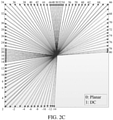
- the test model VTM5.0 of VVC defines spatial prediction modes in 94 components indexed from -14 to 80, herein including two non-angular modes, namely Planar mode (hereinafter referred to as a planar prediction mode) indexed 0 and DC mode indexed 1 (hereinafter referred to a DC prediction mode).
- Planar mode hereinafter referred to as a planar prediction mode
- DC mode indexed 1 hereinafter referred to a DC prediction mode
- the index is used for uniquely identifying the prediction mode, and may be used as a mode index when in use.
- an intra prediction an intra spatial prediction within the components is performed on the current block by using one or more prediction modes among the spatial prediction modes within the 94 components.
- the method for processing information according to an embodiment of the present application is mainly applied to the intra prediction unit 213 shown in FIG. 2A and the intra prediction unit 223 shown in FIG. 2B , and is used for obtaining a intra prediction value of the current block. That is to say, the method for processing information according to an embodiment of the present application may be applied to the video encoder 21, or the video decoder 22, or may even be applied to the video encoder and the video decoder at the same time, which is not specifically limited in an embodiment of the present application.
- the "current block” refers to a coding block in the unit 213; when the method described below is used in the unit 223, the "current block” refers to a coding block in the unit 223.
- the intra prediction process mainly includes following acts S201 to S204.
- the act S201 before performing luma and chroma predictions on the current block (which may be a coding block or a coding block), it is necessary to obtain values of reference pixels around the current block first. If none of the reference pixels exists, the pixel value of 512 is used for filling; if only part of the reference pixels do not exist, values of the nearest existing reference pixels are used for filling.
- the act S202 it is determined whether the reference pixels need to be filtered according to a specific condition such as the prediction mode, or a size of the current block, etc. If filtering is needed, a three-tap smoothing filter with a coefficient of [1,2,1] is used to filter the reference pixels.
- the reference pixels are used to predict the current block, to obtain a prediction value of each pixel in the current block.
- the planar prediction mode is a prediction mode indexed 0 in the intra prediction modes shown in FIG. 2C
- the DC prediction mode is a prediction mode indexed 1 in the intra prediction modes shown in FIG. 2C
- the horizontal prediction mode is a prediction mode indexed 18 in the intra prediction modes shown in FIG. 2C
- the vertical prediction mode is a prediction mode indexed 50 in the intra prediction modes shown in FIG. 2C .
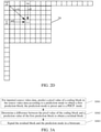
- a principle of the PDPC is to refine the prediction value according to a left reference pixel (left), a top reference pixel (top), and a top left corner reference pixel (topleft) of the current block, and then determine a residual error between the refined prediction value and a value of the corresponding pixel in the current block.
- a distance between the left and a current point ( x , y ) in the current block 24 (which may be represented by a weight wL), a value P top of a reconstructed pixel on the top reference pixel (top), a distance between the top and the current point ( x , y ) (which may be represented by the weight wT), a value P topleft of a reconstructed pixel on the top left corner reference pixel topleft, and a distance between the topleft and the current point ( x , y ) (which may be represented by a weight wTL), of a current block 24, the prediction value Q ( x , y ) of the current point ( x , y ) is refined to obtain the refined prediction value P ( x , y ).
- An embodiment of the present application provides a method for processing information, wherein the method is applied to the video encoder 21 of the electronic device.
- Functions implemented by the method may be realized by calling program codes by a processor in the electronic device.
- the program codes may be stored in a computer storage medium. It may be seen that the electronic device at least includes the processor and a storage medium.
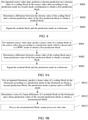
- FIG. 3A is a schematic flowchart of an implementation of a method for processing information according to an embodiment of the present application. As shown in FIG. 2 , the method includes following acts 301 to 303.
- a colour component of a coding block in the source video data is predicted according to a prediction mode to obtain a first prediction block, wherein the prediction mode is preset and is a PDCP mode.
- the colour component is a chroma value or a luma value.
- a prediction mode used when predicting the current block (including the coding block and the coding block) before using the PDPC is defined as the PDPC mode.
- the PDPC mode includes a planar prediction mode, a DC prediction mode, a horizontal prediction mode, a vertical prediction mode, an angular prediction mode with an index smaller than or equal to 10 (including the wide-angle mode), or an angular prediction mode with an index greater than or equal to 58 (including the wide-angle mode).
- a coding block refers to a picture area in the source video data on which prediction processing and coding processing need to be performed.
- the source video data may be obtained by a picture acquisition apparatus.
- the act S302 is directly performed to determine a difference between the colour component of the coding block and a prediction value of the first prediction block.
- PDPC processing is not performed on the first prediction block, which can reduce processing complexity of intra prediction.
- the difference between the colour component of the coding block and the prediction value of the first prediction block is determined to obtain the residual block.
- the residual block and the prediction mode are signalled in a bitstream.
- the difference between the prediction value of the first prediction block and the colour component of the coding block is directly determined. In this way, on the premise of ensuring video coding performance, processing complexity of intra prediction can be reduced.
- FIG. 3B is a schematic flowchart of an implementation of another method for processing information according to an embodiment of the present application. As shown in FIG. 3B , the method includes following acts S311 to S313.
- a colour component of a coding block in the bitstream is predicted according to a prediction mode in the bitstream to obtain a second prediction block; wherein, the prediction mode is preset and is a PDCP mode.
- the colour component is a chroma value or a luma value.
- a sum of a difference of a residual block in the bitstream and a prediction value of the second prediction block is determined to obtain a reconstructed block.
- the reconstructed block is processed, outputting processed video data.
- a colour component of a coding block in the bitstream is predicted to obtain a second prediction block, wherein the prediction mode is preset and is the PDCP mode.
- the prediction mode is preset and is the PDCP mode.
- FIG. 4A is a schematic flowchart of an implementation of yet another method for processing information according to an embodiment of the present application. As shown in FIG. 4A , and the method includes following acts S401 to S403.
- a chroma prediction is performed on a chroma value of a coding block in the source video data according to a prediction mode to obtain a first prediction block, wherein the prediction mode is preset and is a PDCP mode.
- the improvement of video coding and decoding performance by the PDPC is based on saving coding bits and sacrificing chroma performance. Since contents of pictures reflected by luma and chroma are different, refining the first prediction block by the PDPC cannot improve performances of luma and chroma simultaneously.
- a chroma residual block is directly determined according to the coding block and the first prediction block.
- a difference between the chroma value of the coding block and a chroma prediction value of the first prediction block is determined to obtain a residual block.
- the obtained residual block is a chroma residual block, that is, it includes the difference between the chroma value of the coding block and a luma prediction value of the first prediction block.
- the residual block and the prediction mode are signalled in a bitstream.
- the residual value is directly determined. In this way, processing complexity of chroma intra prediction is reduced without affecting chroma performance.
- the method further includes following acts S404 to S407.
- a luma prediction is performed on a luma value of the coding block according to a prediction mode which is preset and is the PDPC mode to obtain the first prediction block.
- the prediction value of the first prediction block is refined to obtain a first refinement block.
- a difference between the luma value of the coding block and a corresponding refinement value of the first refinement block is determined to obtain a refinement residual block.
- the refined residual block and the prediction mode are signalled in the bitstream.
- the video encoder may also execute acts S901 to S903 in a following embodiment, or execute acts S101 to S103 in a following embodiment.
- FIG. 4B is a schematic flowchart of an implementation of further another method for processing information according to an embodiment of the present application. As shown in FIG. 4B , the method includes following acts S411 to S413.
- a chroma value of a coding block in the bitstream is predicted according to a prediction mode in the bitstream to obtain a second prediction block; wherein the prediction mode is preset and is the PDCP mode.
- a sum of a chroma difference of a residual block in the bitstream and a chroma prediction value of the second prediction block is determined to obtain a reconstructed block.
- the reconstructed block is processed, outputting processed video data.
- the chroma value of the coding block in the bitstream is predicted according to the prediction mode in the bitstream to obtain the second prediction block, wherein the prediction mode is predicted and is the PDPC mode.
- the residual block and the second prediction block are directly added together to obtain the reconstructed block, the reconstructed block is processed, and the processed video data is output. In this way, processing complexity of chroma intra prediction is reduced without affecting chroma performance.
- the method further includes following acts S414 to S417.
- a luma value of the coding block in the bitstream is predicted according to the prediction mode in the bitstream to obtain a second prediction block; wherein the prediction mode is preset and is the PDCP mode.
- a luma prediction value of the second prediction block is refined to obtain a second refinement block.
- a sum of a luma difference of a residual block in the bitstream and the luma prediction value of the second refinement block is determined to obtain a reconstructed block.
- the reconstructed block is processed, outputting processed video data.
- the video decoder may also execute acts S911 to S913 in a following embodiment, or in another embodiment, the prediction mode in act S911 is any prediction mode in any one of following first to fourth mode combinations.
- FIG. 5 is a schematic flowchart of an implementation of another method for processing information according to an embodiment of the present application. As shown in FIG. 5 , the method includes following acts S501 to S503.
- a chroma prediction is performed on a chroma value of a coding block in the source video data according to any prediction mode in a first mode combination to obtain a first prediction block.
- the first mode combination includes following PDPC modes: a prediction mode with an index smaller than a first numerical value but not the planar prediction mode or the DC prediction mode, a prediction mode with an index greater than the first numerical value and smaller than or equal to a second numerical value, a prediction mode with an index greater than or equal to a third numerical value and smaller than a fourth numerical value, and a prediction mode with an index greater than the fourth numerical value, among N preset spatial prediction modes within a component.
- the first numerical value, the second numerical value, the third numerical value, and the fourth numerical value are usually preset mode index sequence values (that is, values of the indexes).
- the N spatial prediction modes within the component are the spatial prediction modes within the 94 components shown in FIG.
- the second numerical value is set to 10
- the third numerical value is set to 58
- the fourth numerical value is set to 66, that is, when the chroma prediction is performed, and when any one of a prediction mode with an index smaller than 2 but not the planar prediction mode or the DC prediction mode, a prediction mode with an index greater than 2 and smaller than or equal to 10, a prediction mode with an index greater than or equal to 58 and smaller than 66, and a prediction mode with an index greater than 66, among the spatial prediction modes within these 94 components, is used, an obtained chroma prediction value is not refined by using the PDPC. In other words, only in the planar prediction mode, the DC prediction mode, the horizontal prediction mode, the vertical prediction mode, the prediction mode indexed 2, and the prediction mode indexed 66, the obtained chroma prediction value is refined by using the PDPC.
- a difference between the chroma value of the coding block and the chroma prediction value of the first prediction block is determined to obtain a residual block.
- the residual block and the prediction mode are signalled in a bitstream.
- the difference between the chroma prediction value and the chroma value of the coding block is directly determined. In this way, on the basis of ensuring chroma prediction performance, processing complexity of chroma prediction is reduced.
- the method further includes the aforementioned acts S403 to S407.
- acts S901 to S903 in a following embodiment may also be performed, or acts S101 to S103 in a following embodiment may be performed.
- the video decoder may execute decoding acts which are symmetrical with the above acts S501 to S503, which is not repeated here.
- the video decoder may also perform acts S911 to S913 in a following embodiment, or in another embodiment, the prediction mode in act S911 is any prediction mode in any one of the first to fourth mode combinations.
- FIG. 6 is a schematic flowchart of an implementation of yet another method for processing information according to an embodiment of the present application. As shown in FIG. 6 , the method includes following acts S601 to S603.
- a chroma prediction is performed on a chroma value of a coding block in the source video data according to any prediction mode in the second mode combination to obtain a first prediction block.
- the second mode combination includes following PDPC modes: a prediction mode with an index smaller than or equal to a second numerical value but not the planar prediction mode or the DC prediction mode, and a prediction mode with an index greater than or equal to a third numerical value, among N preset spatial prediction modes within a component.
- the second numerical value and the third numerical value are usually preset mode index sequence values (that is, values of the indexes).
- the N spatial prediction modes within the component are the spatial prediction modes within the 94 components shown in FIG. 2C , and the second numerical value is set to 10, and the third numerical value is set to 58. That is, when the chroma prediction is performed, and when any one of a prediction mode with an index smaller than or equal to 10 but not the planar prediction mode or the DC prediction mode, and a prediction mode with an index greater than or equal to 58, among the spatial prediction modes within these 94 components, is used, an obtained chroma prediction value is not refined by using the PDPC. In this way, processing complexity of chroma prediction can be reduced. In other words, only in the planar prediction mode, the DC prediction mode, the horizontal prediction mode, and the vertical prediction mode, the obtained chroma prediction value is refined by using the PDPC.
- the N spatial prediction modes within the component are the spatial prediction modes within the 94 components shown in FIG. 2C , and the second numerical value is set to 8, and the third numerical value is set to 60.
- the difference between the chroma value of the coding block and the chroma prediction value of the first prediction block is determined to obtain a residual block.
- the residual block and the prediction mode are signalled in a bitstream.
- a residual value is directly determined without refining the prediction value.
- chroma coding performance is improved.
- Experimental data show that a performance of a Y component is lost by 0.03%; a performance of a U component is increased by 0.16%, and a performance of a V component is increased by 0.14%. It can be seen that the performance loss of the Y component is basically unchanged; and performance improvement of the U component and performance improvement of the V component are obviously improved.
- the method further includes the aforementioned acts S403 to S407.
- acts S901 to S903 in a following embodiment may also be performed, or acts S101 to S103 in a following embodiment may be performed.
- the video decoder may execute decoding acts which are symmetrical with the above acts S601 to S603, which will not be repeated here.
- acts S911 to S913 in a following embodiment may also be performed, and in another embodiment, the prediction mode in act S911 is any prediction mode in any one of the first to fourth mode combinations.
- FIG. 7 is a schematic flowchart of an implementation of further another method for processing information according to an embodiment of the present application. As shown in FIG. 7 , the method includes following acts S701 to S703.
- a chroma prediction is performed on a chroma value of a coding block in the source video data according to any prediction mode in the third mode combination to obtain a first prediction block.
- the third mode combination includes following PDPC modes: the horizontal prediction mode, the vertical prediction mode, and a prediction mode with an index smaller than or equal to a second numerical value but not the planar prediction mode or the DC prediction mode, and a prediction mode with an index greater than or equal to a third numerical value, among N preset spatial prediction modes within a component.
- the second numerical value and the third numerical value are usually preset mode index sequence values (that is, values of the indexes).
- the N spatial prediction modes within the component are the spatial prediction modes within the 94 components shown in FIG. 2C , and the second numerical value is set to 10, and the third numerical value is set to 58, that is, the third mode combination includes following PDPC modes: the horizontal prediction mode, the vertical prediction mode, and a prediction mode with an index smaller than or equal to 10 but not the planar prediction mode or the DC prediction mode, and a prediction mode with an index greater than or equal to 58, among the spatial prediction modes within the 94 components.
- an obtained chroma prediction value is refined by using the PDPC, while in the third mode combination, the obtained chroma prediction value is not refined by using the PDPC, thus reducing processing complexity of chroma prediction.
- a difference between the chroma value of the coding block and the chroma prediction value of the first prediction block is determined to obtain a residual block.
- the residual block and the prediction mode are signalled in a bitstream.
- the method further includes the aforementioned acts S403 to S407.
- acts S901 to S903 in a following embodiment may also be performed, or acts S101 to S103 in a following embodiment may be performed.
- the video decoder executes decoding acts which are symmetrical with the above acts S701 to S703, which will not be repeated here.
- the video decoder may also execute the above acts S414 to S417, or execute acts S911 to S913 in a following embodiment, or in another embodiment, the prediction mode in act S911 is any prediction mode in any one of the first to fourth mode combinations.
- FIG. 8 is a schematic flowchart of an implementation of another method for processing information according to an embodiment of the present application. As shown in FIG. 8 , the method includes following acts S801 to S803.
- a chroma prediction is performed on a chroma value of a coding block in the source video data according to any prediction mode in a fourth mode combination to obtain a first prediction block.
- the fourth mode combination includes following PDPC modes: the horizontal prediction mode, the vertical prediction mode, and a prediction mode with an index smaller than or equal to a second numerical value and including the planar prediction mode and the DC prediction mode, and a prediction mode with an index greater than or equal to a third numerical value, among N preset spatial prediction modes within a component.
- the second numerical value and the third numerical value are usually preset mode index sequence values (that is, values of the indexes).
- the N spatial prediction modes within the component are the spatial prediction modes within the 94 components shown in FIG. 2C , and the second numerical value is set to 10, and the third numerical value is set to 58, that is, the fourth mode combination includes following PDPC modes: the horizontal prediction mode, the vertical prediction mode, and a prediction mode with an index smaller than or equal to 10, and a prediction mode with an index greater than or equal to 58, among the N spatial prediction modes within the component.
- a difference between the chroma value of the coding block and the chroma prediction value of the first prediction block is determined to obtain a residual block.
- the residual block and the prediction mode are signalled in a bitstream.
- the method also includes acts S401 to S403, or acts S501 to S503, or acts S601 to S603, or acts S701 to S703 in the above embodiments, or following acts S901 to S903.
- the video decoder may execute decoding acts which are symmetrical with the above acts S801 to S803, which is not repeated here.
- the video decoder may also perform acts S414 to S417 above, or perform acts S911 to S914 in following embodiments, or in another embodiment, a prediction mode in act S911 is any prediction mode in any of the first to fourth mode combinations.
- FIG. 9 is a schematic flowchart of an implementation of yet another method for processing information according to an embodiment of the present application. As shown in FIG. 9A , the method includes following acts S901 to S903.
- a luma value of a coding block in the source video data is predicted according to the prediction mode which is preset and is the PDPC mode to obtain a first prediction block.
- a difference between a luma value of the coding block and a luma prediction value of the first prediction block is determined to obtain a residual block.
- the residual block and the prediction mode are signalled in a bitstream.
- the obtained luma prediction value is not refined by using the PDPC, so that processing complexity of luma prediction can be reduced.
- the method also includes acts S401 to S403, or acts S501 to S503, or acts S601 to S603, or acts S701 to S703, or acts S801 to S803 in the above embodiments.
- FIG. 9B is a schematic flowchart of an implementation of further another method for processing information according to an embodiment of the present application. As shown in FIG. 9B , the method includes following acts S911 to S913.
- a luma value of a coding block in the bitstream is predicted according to a prediction mode in the bitstream to obtain a second prediction block; wherein the prediction mode is preset and is the PDCP mode.
- the prediction mode in act S911 is any prediction mode in any of the first to fourth mode combinations.
- a sum of a luma difference of a residual block in the bitstream and a luma prediction value of the second prediction block is determined to obtain a reconstructed block.
- the reconstructed block is processed, outputting processed video data.
- FIG. 10 is a schematic flowchart of an implementation of another method for processing information according to an embodiment of the present application. As shown in FIG. 10 , the method includes following acts S101 to S103.
- a luma prediction is performed on a luma value of a coding block in the source video data according to any prediction mode in any one of the first to fourth mode combinations to obtain the first prediction block.
- a difference between the luma value of the coding block and a luma prediction value of the first prediction block is determined to obtain a residual block.
- the residual block and the prediction mode are signalled in a bitstream.
- the method also includes acts S401 to S403, or acts S501 to S503, or acts S601 to S603, or acts S701 to S703, or acts S801 to S803 in the above embodiments.
- FIG. 11A is a schematic flowchart of an implementation of yet another method for processing information according to an embodiment of the present application. As shown in FIG. 11A , the method includes following acts S1101 to S1104.
- a colour component of a coding block in the source video data is predicted according to a prediction mode to obtain a third prediction block, wherein the prediction mode is preset and is the PDCP mode.
- the colour component is a luma value or a chroma value.
- the third prediction block is refined according to the prediction mode to obtain a third refinement block.
- a difference between the colour component of the coding block and a refinement value of the third refinement block is determined to obtain a residual block.
- the residual block and the prediction mode are signalled in a bitstream.
- the colour component of the coding block in the source video data is predicted according to the prediction mode to obtain the third prediction block, which includes: a chroma prediction is performed on the chroma value of the coding block according to any prediction mode in a fifth mode combination to obtain the third prediction block; wherein the fifth mode combination includes following PDPC modes: the planar prediction mode, the DC prediction mode, the horizontal prediction mode, the vertical prediction mode, a prediction mode with an index being a first numerical value among N preset spatial prediction modes within a component, and a prediction mode with an index being a fourth numerical value among the N preset spatial prediction modes within a component.
- the colour component of the coding block in the source video data is predicted according to the prediction mode to obtain the third prediction block, which includes: the colour component of the coding block is predicted according to the prediction mode to obtain the third prediction block, when following cases 1 to 4 are all met.
- the coding block is a luma block, and an Intra Sub-Partitions is not used; or, the coding block is a chroma block.
- the coding block is a luma block, and a Oth reference line is used for prediction; or, the coding block is a chroma block; wherein the Oth reference line refers to a reference line closest to the coding block.
- the coding block is not coded by using a Block-based Delta Pulse Code Modulation (BDPCM).
- BDPCM Block-based Delta Pulse Code Modulation
- the prediction mode is a horizontal prediction mode; the prediction mode is a vertical prediction mode; the prediction mode is a prediction mode with an index being the first numerical value among the N preset spatial prediction modes within a component; the prediction mode is a prediction mode with the index being the fourth numerical value; the prediction mode is a prediction mode with the index smaller than or equal to a second numerical value, and the coding block is not a chroma block; or, the prediction mode is a prediction mode with the index greater than or equal to a third numerical value, and the coding block is not a chroma block.
- the colour component of the coding block in the source video data is predicted according to the prediction mode to obtain the third prediction block, which includes: a chroma prediction is performed on the chroma value of the coding block according to any prediction mode in a sixth mode combination to obtain the third prediction block; wherein the sixth mode combination includes following PDPC modes: the planar prediction mode, the DC prediction mode, the horizontal prediction mode, and the vertical prediction mode.
- the colour component of the coding block in the source video data is predicted according to the prediction mode to obtain the third prediction block, which includes: the colour component of the coding block is predicted according to the prediction mode to obtain the third prediction block, when following cases 1 to 4 are all met.
- the coding block is a luma block, and the Intra Sub-Partitions is not used; or, the coding block is a chroma block.
- the Oth reference line is used for prediction; or, the coding block is a chroma block; wherein the Oth reference line refers to the reference line closest to the coding block.
- the coding block is not coded by using the BDPCM.
- the prediction mode is the planar prediction mode; the prediction mode is the DC prediction mode; the prediction mode is the horizontal prediction mode; the prediction mode is the vertical prediction mode; the prediction mode is a prediction mode with the index smaller than or equal to the second numerical value, and the coding block is not a chroma block; or, the prediction mode is a prediction mode with the index greater than or equal to the third numerical value, and the coding block is not a chroma block.
- the colour component of the coding block in the source video data is predicted according to the prediction mode to obtain the third prediction block, which includes: a chroma prediction is performed on the chroma value of the coding block according to any prediction mode in a seventh mode combination to obtain the third prediction block; wherein the seventh mode combination includes following PDPC modes: the planar prediction mode, and the DC prediction mode.
- the colour component of the coding block in the source video data is predicted according to the prediction mode to obtain the third prediction block, which includes: the colour component of the coding block is predicted according to the prediction mode to obtain the third prediction block, when following cases 1 to 4 are all met.
- the coding block is a luma block, and the Intra Sub-Partitions is not used; or, the coding block is a chroma block.
- the Oth reference line is used for prediction; or, the coding block is a chroma block; wherein the Oth reference line refers to the reference line closest to the coding block.
- the coding block is not coded by using the BDPCM.
- the prediction mode is the planar prediction mode; the prediction mode is the DC prediction mode; the prediction mode is the horizontal prediction mode, and the coding block is not a chroma block; the prediction mode is the vertical prediction mode, and the coding block is not a chroma block; the prediction mode is a prediction mode with the index smaller than or equal to the second numerical value, and the coding block is not a chroma block; or, the prediction mode is a prediction mode with the index greater than or equal to the third numerical value, and the coding block is not a chroma block.
- the colour component of the coding block in the source video data is predicted according to the prediction mode to obtain the third prediction block, which includes: when following cases 1 to 4 are all met, the colour component of the coding block is predicted according to the prediction mode to obtain the third prediction block.
- the coding block is a luma block, and the Intra Sub-Partitions is not used.
- the coding block is a luma block
- the Oth reference line is used for prediction; wherein the Oth reference line refers to the reference line closest to the coding block.
- the coding block is not coded by using the BDPCM.
- the prediction mode is the planar prediction mode; the prediction mode is the DC prediction mode; the prediction mode is the horizontal prediction mode; the prediction mode is the vertical prediction mode; the prediction mode is a prediction mode with the index smaller than or equal to the second numerical value; or, the prediction mode is a prediction mode with the index greater than or equal to the third numerical value.
- FIG. 11B is a schematic flowchart of an implementation of further another method for processing information according to an embodiment of the present application. As shown in FIG. 11B , the method includes following acts S1121 to S1124.
- a colour component of a coding block in the bitstream is predicted according to a prediction mode in the bitstream to obtain a fourth prediction block; wherein the prediction mode is preset and is a PDCP mode.
- the colour component is a chroma value or a luma value.
- the fourth prediction block is refined according to the prediction mode to obtain a fourth refinement block.
- a sum of a difference of a residual block in the bitstream and a refinement value of the fourth refinement block is determined to obtain a reconstructed block.
- the reconstructed block is processed, outputting processed video data.
- the PDPC is applied to the planar prediction mode, the DC prediction mode, the horizontal prediction mode, the vertical prediction mode, and an angular prediction mode with an index smaller than or equal to 10 and an angular prediction mode with an index greater than or equal to 58 among the N spatial prediction modes within the component, in luma block and chroma block prediction modes simultaneously, that is, after predicting a current block by using these prediction modes, a prediction value obtained by the prediction will be refined by using the PDPC.
- VTM5.0 it is stipulated that when all following cases (101) to (104) are met, the PDPC is used.
- the Intra Sub-Partitions (ISP) is not used; or, the current block is a chroma block.
- a Oth reference line is used for prediction; or, the current block is a chroma block; wherein the Oth reference line refers to a reference line closest to the current block.
- the current block is not coded by using a Block-based Delta Pulse Code Modulation (BDPCM).
- BDPCM Block-based Delta Pulse Code Modulation
- the prediction mode is the planar prediction mode, the DC prediction mode, the horizontal prediction mode, the vertical prediction mode, the angular prediction mode with the index smaller than or equal to 10, or the angular prediction mode with the index greater than or equal to 58.
- An embodiment of the present application provides a method for modifying the PDPC mode, which reduces chroma prediction modes using PDPC, after this limitation, time complexity will be reduced, and at the same time, chroma coding performance is improved.
- the detailed description is as follows.
- PDPC modes in related technologies are same in luma and chroma, and they all use the planar prediction mode, the DC prediction mode, the horizontal prediction mode, the vertical prediction mode, the angular prediction mode with the index smaller than or equal to 10, or the angular prediction mode with the index greater than or equal to 58.
- the chroma prediction is modified as, when a chroma prediction is performed on a current block by using any one of a prediction mode with an index smaller than or equal to 10 but not the planar prediction mode or the DC prediction mode, and a prediction mode with an index greater than or equal to 58, among the spatial prediction modes within the 94 components shown in FIG. 2C , an obtained chroma prediction value is not refined by using the PDPC.
- the chroma prediction mode using PDPC is reduced as, PDPC is used only for the planar prediction mode, the DC prediction mode, the horizontal prediction mode or the vertical prediction mode; and when the luma prediction is performed on the current block, the luma prediction modes using PDPC are still the planar prediction mode, the DC prediction mode, the horizontal prediction mode, the vertical prediction mode, and the angular prediction mode with the index smaller than or equal to 10 and the angular prediction mode with the index greater than or equal to 58 among the spatial prediction modes within the 94 components, that is, the luma prediction modes using PDPC keep unchanged.
- the current block is a luma block
- the ISP partition is not used; or, the current block is a chroma block.
- the current block is a luma block
- the Oth reference line is used for prediction; or, the current block is a chroma block.
- the current block is not coded by using the BDPCM.
- the prediction mode is the planar prediction mode, the DC prediction mode, the horizontal prediction mode, the vertical prediction mode, the angular prediction mode with the index being smaller than or equal to 10 and the current block being not the chroma block, or the angular prediction mode with the index being greater than or equal to 58 and the current block being not the chroma block.
- the above method for modifying the PDPC mode provided by an embodiment of the present application can obtain following beneficial effects on the premise of basically not affecting performance.
- a performance of a Y component is lost by 0.03%; a performance of a U component is improved by 0.16%, and a performance of a V component is increased by 0.14%. It can be seen that the performance loss of the Y component is basically unchanged; and the performance improvement of the U component and the performance improvement of the V component are obviously improved.
- complexity can be reduced.
- PDPC digital signal processing
- the chroma prediction modes using PDPC can be reduced to 4 chroma prediction modes, thereby saving processing complexity, and finally decoding time is greatly shortened.
- a protection point of an embodiment of the present application is to modify a usage scenario of PDPC in a chroma prediction.
- No matter PDPC is used only for the planar prediction mode, the DC prediction mode, the horizontal prediction mode, and the vertical prediction mode in the chroma prediction modes in a main solution, or part of the chroma prediction modes in an alternative solution are prohibited from using PDPC, it is to reduce the prediction modes using PDPC under the chroma prediction, reduce complexity of algorithm, and improve coding performance of chroma.
- alternative solutions mainly include following solutions.
- the chroma prediction is modified as, when the chroma prediction is performed on the current block by using any one of the horizontal prediction mode, the vertical prediction mode, and a prediction mode with an index smaller than or equal to 10, and a prediction mode with an index greater than or equal to 58, among the spatial prediction modes within the 94 components shown in FIG. 2C , an obtained chroma prediction value is not refined by using the PDPC. That is, all chroma prediction modes are prohibited from using PDPC, while the luma prediction mode using PDPC keeps unchanged when the luma prediction is performed on the current block.
- VTM5.0 syntax semantics in VTM5.0 are modified as, PDPC is used when following cases (301) to (305) are all met.
- the current block is a luma block.
- the current block is not coded by using the BDPCM.
- the prediction mode is the planar prediction mode, the DC prediction mode, the horizontal prediction mode, the vertical prediction mode, the angular prediction mode with the index smaller than or equal to 10, or the angular prediction mode with the index greater than or equal to 58.
- the chroma prediction is modified as, when the chroma prediction is performed on the current block by using any one of the horizontal prediction mode, the vertical prediction mode, and the prediction mode with the index smaller than or equal to 10 but not the planar prediction mode or the DC prediction mode, and the prediction mode with the index greater than or equal to 58, among the spatial prediction modes within the 94 components, an obtained chroma prediction value is not refined by using the PDPC.
- PDPC when the chroma prediction is performed, PDPC is used only in the planar prediction mode and the DC prediction mode; when the luma prediction is performed on the current block, the luma prediction mode using PDPC keeps unchanged.
- VTM5.0 syntax semantics in VTM5.0 are modified as, PDPC is used when following conditions (401) to (404) are all met.
- the current block is a luma block
- the ISP partition is not used; or, the current block is a chroma block.
- the current block is a luma block
- the Oth reference line is used for prediction; or, the current block is a chroma block.
- the prediction mode is the planar prediction mode, the DC prediction mode, the horizontal prediction mode with the current block being not the chroma block, the vertical prediction mode with the current block being not the chroma block, the angular prediction mode with the index being smaller than or equal to 10 and the current block being not the chroma block, or the angular prediction mode with the index being greater than or equal to 58 and the current block being not the chroma block.
- the chroma prediction is modified as, when the chroma prediction is performed on the current block by using any one of the prediction mode with the index smaller than 2 but not the planar prediction mode or the DC prediction mode, the prediction mode with the index greater than 2 and smaller than or equal to 10, the prediction mode with the index greater than or equal to 58 and smaller than 66, and the prediction mode with the index greater than 66, among the spatial prediction modes within the 94 components, an obtained chroma prediction value is not refined by using the PDPC.
- PDPC is used only in any one of the planar prediction mode, the DC prediction mode, the horizontal prediction mode, the vertical prediction mode, the prediction mode indexed 2, and the prediction mode indexed 66; when the luma prediction is performed on the current block, the luma prediction mode using PDPC keeps unchanged.
- VTM5.0 syntax semantics in VTM5.0 are modified as, PDPC is used when following cases (501) to (504) are all met.
- the current block is a luma block
- the ISP partition is not used; or, the current block is a chroma block.
- the current block is a luma block
- the Oth reference line is used for prediction; or, the current block is a chroma block.
- the prediction mode is the planar prediction mode, the DC prediction mode, the horizontal prediction mode, the vertical prediction mode, the prediction mode indexed 2, the prediction mode indexed 66, the angular prediction mode with the index being smaller than or equal to 10 and the current block being not the chroma block, or the angular prediction mode with the index being greater than or equal to 58 and the current block being not the chroma block.
- VTM5.0 syntax semantics in VTM5.0 are modified as, PDPC is used when following cases (601) to (604) are met.
- the current block is a luma block
- the ISP partition is not used; or, the current block is a chroma block.
- the current block is a luma block
- the Oth reference line is used for prediction; or, the current block is a chroma block.
- the prediction mode is the planar prediction mode, the DC prediction mode, the horizontal prediction mode, the vertical prediction mode, an angular prediction mode with an index smaller than or equal to 8, and an angular prediction mode with an index greater than or equal to 60.
- an embodiment of the present application provides an apparatus for processing information, wherein various modules included in the apparatus and various units included in the modules may be implemented by a processor in an electronic device. Of course, they may also be implemented by a specific logic circuit.
- the processor may be a central processing unit (CPU), a microprocessor (MPU), a digital signal processor (DSP) or a field programmable gate array (FPGA), etc.
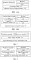
- FIG. 12A is a schematic structure diagram of an apparatus for processing information according to an embodiment of the present application.
- the apparatus 120 for processing information includes a prediction module 121, a residual determination module 122, and a signalling module 123.
- the prediction module 121 is configured to, for inputted source video data, predict a colour component of a coding block in the source video data according to a prediction mode to obtain a first prediction block, wherein the prediction mode is preset and is a PDCP mode.
- the residual determination module 122 is configured to determine a difference between the colour component of the coding block and a prediction value of the first prediction block to obtain a residual block.
- the signalling module 123 is configured to signal the residual block and the prediction mode in a bitstream.
- the colour component is a luma value or a chroma value.
- the prediction module 121 includes a chroma prediction unit 1210, configured to perform a chroma prediction on a chroma value of the coding block according to any prediction mode in a first mode combination to obtain the first prediction block.
- the first mode combination includes following PDPC modes: a prediction mode with an index smaller than a first numerical value but not a planar prediction mode or a DC prediction mode, a prediction mode with an index greater than the first numerical value and smaller than or equal to a second numerical value, a prediction mode with an index greater than or equal to a third numerical value and smaller than a fourth numerical value, and a prediction mode with an index greater than the fourth numerical value, among N preset spatial prediction modes within a component.
- the chroma prediction unit 1210 is configured to perform the chroma prediction on the chroma value of the coding block according to any prediction mode in a second mode combination to obtain the first prediction block.
- the second mode combination includes following PDPC modes: a prediction mode with an index smaller than or equal to the second numerical value but not a planar prediction mode or a DC prediction mode, and a prediction mode with an index greater than or equal to the third numerical value, among the N preset spatial prediction modes within the component.
- the chroma prediction unit 1210 is configured to perform the chroma prediction on the chroma value of the coding block according to any prediction mode in a third mode combination to obtain the first prediction block.
- the third mode combination includes following PDPC modes: a horizontal prediction mode, a vertical prediction mode, and a prediction mode with an index smaller than or equal to the second numerical value but not a planar prediction mode or a DC prediction mode, and a prediction mode with an index greater than or equal to the third numerical value, among the N preset spatial prediction modes within the component.
- the chroma prediction unit 1210 is configured to perform the chroma prediction on the chroma value of the coding block according to any prediction mode in a fourth mode combination to obtain the first prediction block.
- the fourth mode combination includes following PDPC modes: the vertical prediction mode, and a prediction mode with an index smaller than or equal to the second numerical value and including a planar prediction mode and a DC prediction mode, and a prediction mode with an index greater than or equal to the third numerical value among the N preset spatial prediction modes within the component.
- the prediction module 121 further includes a luma prediction unit 1212, configured to perform a luma prediction on a luma value of the coding block according to any prediction mode in any one of the first to fourth mode combinations to obtain the first prediction block.
- a luma prediction unit 1212 configured to perform a luma prediction on a luma value of the coding block according to any prediction mode in any one of the first to fourth mode combinations to obtain the first prediction block.
- FIG. 13 is a schematic structure diagram of another apparatus for processing information according to an embodiment of the present application.
- the apparatus 130 for processing information includes a prediction module 131, a recovery module 132, and a video output module 133.
- the prediction module 131 is configured to: for an inputted bitstream, predict a colour component of a coding block in the bitstream according to a prediction mode in the bitstream to obtain a second prediction block; wherein the prediction mode is preset and is a PDCP mode.
- the recovery module 132 is configured to determine a sum of a difference of a residual block in the bitstream and a prediction value of the second prediction block to obtain a reconstructed block.
- the video output module 133 is configured to process the reconstructed block and output processed video data.
- the colour component is a chroma value or a luma value.
- the prediction mode is any prediction mode in the first mode combination.
- the first mode combination includes following PDPC modes: a prediction mode with an index smaller than a first numerical value but not a planar prediction mode or a DC prediction mode, a prediction mode with an index greater than the first numerical value and smaller than or equal to a second numerical value, a prediction mode with an index greater than or equal to a third numerical value and smaller than a fourth numerical value, and a prediction mode with an index greater than the fourth numerical value, among N preset spatial prediction modes within a component.
- the prediction mode is any prediction mode in the second mode combination.
- the second mode combination includes following PDPC modes: a prediction mode with an index smaller than or equal to the second numerical value but not a planar prediction mode or a DC prediction mode, and a prediction mode with an index greater than or equal to the third numerical value, among the N preset spatial prediction modes within the component.
- the prediction mode is any prediction mode in the third mode combination.
- the third mode combination includes following PDPC modes: a horizontal prediction mode, a vertical prediction mode, and a prediction mode with an index smaller than or equal to the second numerical value but not a planar prediction mode or a DC prediction mode, and a prediction mode with an index greater than or equal to the third numerical value, among the N preset spatial prediction modes within the component.
- the prediction mode is any prediction mode in the fourth mode combination.
- the fourth mode combination includes following PDPC modes: a horizontal prediction mode, a vertical prediction mode, and a prediction mode with an index smaller than or equal to the second numerical value and including a planar prediction mode and a DC prediction mode, and a prediction mode with an index greater than or equal to the third numerical value, among the N preset spatial prediction modes within the component.
- FIG. 14 is a schematic structure diagram of yet another apparatus for processing information according to an embodiment of the present application.
- the apparatus 140 for processing information includes: a prediction module 1401, a refinement module 1402, a residual determination module 1403, and a signalling module 1404.
- the prediction module 1401 is configured to: for inputted source video, predict a colour component of a coding block in the source video data according to a prediction mode to obtain a third prediction block, wherein the prediction mode is preset and is a PDCP mode.
- the refinement module 1402 is configured to refine the third prediction block according to the prediction mode to obtain a third refinement block.
- the residual determination module 1403 is configured to determine a difference between the colour component of the coding block and a refinement value of the third refinement block to obtain a residual block.
- the signalling module 1404 is configured to signal the residual block and the prediction mode in a bitstream.
- the colour component is a luma value or a chroma value.
- the prediction module 1401 is configured to perform a chroma prediction on a chroma value of the coding block according to any prediction mode in a fifth mode combination to obtain the third prediction block.
- the fifth mode combination includes following PDPC modes: a planar prediction mode, a DC prediction mode, a horizontal prediction mode, a vertical prediction mode, a prediction mode with an index being a first numerical value among N preset spatial prediction modes within a component, and a prediction mode with an index being a fourth numerical value among the N preset spatial prediction modes within the component.
- the prediction module 1401 is configured to: when following cases 1 to 4 are all met, predict the colour component of the coding block according to the prediction mode to obtain the third prediction block.
- the coding block is a luma block, and an Intra Sub-Partitions is not used; or, the coding block is a chroma block.
- a Oth reference line is used for prediction; or, the coding block is a chroma block; wherein the Oth reference line refers to a reference line closest to the coding block.
- the coding block is not coded by using a Block-based Delta Pulse Code Modulation (BDPCM).
- BDPCM Block-based Delta Pulse Code Modulation
- the prediction mode is the horizontal prediction mode; the prediction mode is the vertical prediction mode; the prediction mode is a prediction mode with an index being the first numerical value among the N preset spatial prediction modes within a component; the prediction mode is a prediction mode with the index being the fourth numerical value; the prediction mode is a prediction mode with an index smaller than or equal to the second numerical value, and the coding block is not a chroma block; or, the prediction mode is a prediction mode with an index greater than or equal to the third numerical value, and the coding block is not a chroma block.
- the prediction module 1401 is configured to perform the chroma prediction on the chroma value of the coding block according to any prediction mode in a sixth mode combination to obtain the third prediction block.
- the sixth mode combination includes following PDPC modes: the planar prediction mode, the DC prediction mode, the horizontal prediction mode, and the vertical prediction mode.
- the prediction module 1401 is configured to: when following cases 1 to 4 are all met, predict the colour component of the coding block according to the prediction mode to obtain the third prediction block.
- the coding block is a luma block, and the Intra Sub-Partitions is not used; or, the coding block is a chroma block.
- the Oth reference line is used for prediction; or, the coding block is a chroma block; wherein the Oth reference line refers to the reference line closest to the coding block.
- the coding block is not coded by using the BDPCM.
- the prediction mode is the planar prediction mode; the prediction mode is the DC prediction mode; the prediction mode is the horizontal prediction mode; the prediction mode is the vertical prediction mode; the prediction mode is a prediction mode with an index smaller than or equal to the second numerical value and the coding block is not a chroma block; or, the prediction mode is a prediction mode with the index greater than or equal to the third numerical value, and the coding block is not a chroma block.
- the prediction module 1401 is configured to perform the chroma prediction on the chroma value of the coding block according to any prediction mode in a seventh mode combination to obtain the third prediction block; wherein the seventh mode combination includes following PDPC modes: a planar prediction mode, and a DC prediction mode.
- the prediction module 1401 is configured to: when following cases 1 to 4 are all met, predict the colour component of the coding block according to the prediction mode to obtain the third prediction block.
- the coding block is a luma block, and the Intra Sub-Partitions is not used; or, the coding block is a chroma block.
- the 0th reference line is used for prediction; or, the coding block is a chroma block; wherein the 0th reference line refers to the reference line closest to the coding block.
- the coding block is not coded by using the BDPCM.
- the prediction mode is the planar prediction mode; the prediction mode is the DC prediction mode; the prediction mode is the horizontal prediction mode, and the coding block is not a chroma block; the prediction mode is the vertical prediction mode, and the coding block is not a chroma block; the prediction mode is a prediction mode with the index smaller than or equal to the second numerical value and the coding block is not a chroma block; or, the prediction mode is a prediction mode with the index greater than or equal to the third numerical value, and the coding block is not a chroma block.
- the prediction module 1401 is configured to: when following cases 1 to 4 are all met, predict the colour component of the coding block according to the prediction mode to obtain the third prediction block.
- the coding block is a luma block, and an Intra Sub-Partitions is not used.
- the coding block is a luma block, and the 0th reference line is used for prediction; wherein the 0th reference line refers to the reference line closest to the coding block.
- the coding block is not coded by using the BDPCM.
- the prediction mode is the planar prediction mode; the prediction mode is the DC prediction mode; the prediction mode is the horizontal prediction mode; the prediction mode is the vertical prediction mode; the prediction mode is a prediction mode with the index smaller than or equal to the second numerical value; or, the prediction mode is a prediction mode with the index greater than or equal to the third numerical value.
- FIG. 15 is a schematic structure diagram of yet another apparatus for processing information according to an embodiment of the present application.
- the apparatus 150 for processing information includes a prediction module 1501, a refinement module 1502, a recovery module 1503, and a video output module 1504.
- the prediction module 1501 is configured to: for an inputted bitstream, predict a colour component of a coding block in the bitstream according to a prediction mode in the bitstream to obtain a fourth prediction block; wherein the prediction mode is preset and is a PDCP mode.
- the refinement module 1502 is configured to refine the fourth prediction block according to the prediction mode to obtain a fourth refinement block.
- the recovery module 1503 is configured to determine a sum of a difference of a residual block in the bitstream and a refinement value of the fourth refinement block to obtain a reconstructed block.
- the video output module 1504 is configured to process the reconstructed block and output processed video data.
- the colour component is a chroma value or a luma value.
- the computer software product is stored in a storage medium, and includes several instructions to make an electronic device (which may be a mobile phone, a tablet, an electronic reader, an unmanned aerial vehicle, a wearable device (such as smart glasses, or the like), a sweeping robot, a personal computer, a navigator, a video telephone, a television, a server, etc.) perform all or part of the method described in various embodiments of the present application.
- an electronic device which may be a mobile phone, a tablet, an electronic reader, an unmanned aerial vehicle, a wearable device (such as smart glasses, or the like), a sweeping robot, a personal computer, a navigator, a video telephone, a television, a server, etc.
- the aforementioned storage medium includes various media which may store program codes, such as a U disk, a mobile hard disk, a Read Only Memory (ROM), a magnetic disk or an optical disk.
- FIG. 16 is a schematic diagram of a hardware entity of an electronic device according to an embodiment of the present application.
- the electronic device 160 includes a memory 161 and a processor 162.
- the memory 161 stores a computer program that may be run on the processor 162, and the processor 162 implements acts in the method for processing information provided in the above embodiments when executing the program.
- the memory 161 is configured to store instructions and applications executable by the processor 162, and may also buffer data (such as picture data, audio data, voice communication data, and video communication data) to be processed or has been processed by the processor 162 and each module in the electronic device 160, which may be implemented by FLASH or a Random Access Memory (RAM).
- data such as picture data, audio data, voice communication data, and video communication data
- An embodiment of the present application provides a computer readable storage medium, on which a computer program is stored, wherein when the computer program is executed by a processor, acts in the method for processing information provided in the above embodiments are implemented.
- the above units described as separate components may or may not be physically separated, and a component shown as the unit may be or may not be a physical unit; it may be located in one place, or may be distributed over multiple network units. Some or all of the units therein may be selected according to an actual requirement to achieve a purpose of the solution of the present embodiment.
- various functional units in various embodiments of the present application may all be integrated in one processing unit, or each unit may be separately presented as one unit, or two or more units may be integrated in one unit.
- the above-mentioned integrated units may be implemented in a form of hardware, or in a form of hardware plus software functional units.
- all or part of the acts for implementing the above method embodiments may be accomplished by hardware related to program instructions, and the aforementioned program may be stored in a computer readable storage medium.
- the program when executed, performs acts including the above method embodiments.
- the aforementioned storage media include: various media which may store program codes, such as a removable storage device, a Read Only Memory (ROM), a magnetic disk, or an optical disk, etc.
- the integrated units described above in the present application may be stored in a computer readable storage medium, if implemented in a form of software functional module and sold or used as a separate product. Based on this understanding, the technical solutions of the embodiments of the present application, in essence, or the part contributing to the related art, may be embodied in a form of a software product.
- the computer software product is stored in a storage medium, and includes several instructions to make an electronic device (which may be a mobile phone, a tablet, an electronic reader, an unmanned aerial vehicle, a wearable device (such as smart glasses, or the like), a sweeping robot, a personal computer, a navigator, a video telephone, a television, a server, etc.) perform all or part of the method described in various embodiments of the present application.
- an electronic device which may be a mobile phone, a tablet, an electronic reader, an unmanned aerial vehicle, a wearable device (such as smart glasses, or the like), a sweeping robot, a personal computer, a navigator, a video telephone, a television, a server, etc.
- the aforementioned storage medium includes various media which may store program codes, such as a removable storage device, a ROM, a magnetic disk, or an optical disk, etc.
- a colour component of a coding block in the source video data is predicted according to a prediction mode which is preset and is a PDPC mode, after a first prediction block is obtained, each prediction value in the first prediction block is not refined, but a difference between a prediction value of the first prediction block and the colour component of the coding block is directly determined.
Landscapes
- Engineering & Computer Science (AREA)
- Multimedia (AREA)
- Signal Processing (AREA)
- Compression Or Coding Systems Of Tv Signals (AREA)
- Compression Of Band Width Or Redundancy In Fax (AREA)
Abstract
Description
- Embodiments of the present application relate to electronic technology, and relate to but are not limited to a method and an apparatus for processing information, a device, and a storage medium.
- In recent years, video services have developed rapidly in the field of electronic technology. For video services, source video data needs to be coded first, and the coded video data is transmitted to a user terminal through a channel of a mobile communication network or the Internet.
- For a user, fluency of video will directly affect the user's video viewing experience. However, complexity of information processing in video coding directly affects the fluency of the video.
- In view of this, embodiments of the present application provide a method and an apparatus for processing information, a device, and a storage medium, to solve at least one problem existing in related technologies.
- Technical solutions of the embodiments of the present application are implemented as follows.
- In a first aspect, an embodiment of the present application provides a method for processing information, which includes: for inputted source video data, predicting a colour component of a coding block in the source video data according to a prediction mode to obtain a first prediction block, wherein the prediction mode is preset and is a Position-Dependent Prediction Combination (PDPC) mode; determining a difference between the colour component of the coding block and a prediction value of the first prediction block to obtain a residual block; and signalling the residual block and the prediction mode in a bitstream.
- In another embodiment, the colour component is a luma value or a chroma value.
- In another embodiment, predicting the colour component of the coding block according to the prediction mode to obtain the first prediction block includes: performing a chroma prediction on the chroma value of the coding block according to any prediction mode in a first mode combination to obtain the first prediction block; wherein, the first mode combination includes following PDPC modes: a prediction mode with an index smaller than a first numerical value but not a planar prediction mode or a direct current (DC) component prediction mode, a prediction mode with an index greater than the first numerical value and smaller than or equal to a second numerical value, a prediction mode with an index greater than or equal to a third numerical value and smaller than a fourth numerical value, and a prediction mode with an index greater than the fourth numerical value, among N preset spatial prediction modes within a component.
- In another embodiment, predicting the colour component of the coding block according to the prediction mode to obtain the first prediction block includes: performing a chroma prediction on the chroma value of the coding block according to any prediction mode in a second mode combination to obtain the first prediction block; wherein, the second mode combination includes following PDPC modes: a prediction mode with an index smaller than or equal to a second numerical value but not a planar prediction mode or a DC prediction mode, and a prediction mode with an index greater than or equal to a third numerical value, among N preset spatial prediction modes within a component.
- In another embodiment, predicting the colour component of the coding block according to the prediction mode to obtain the first prediction block includes: performing a chroma prediction on the chroma value of the coding block according to any prediction mode in a third mode combination to obtain the first prediction block; wherein, the third mode combination includes following PDPC modes: a horizontal prediction mode, a vertical prediction mode, and a prediction mode with an index smaller than or equal to a second numerical value but not a planar prediction mode or a DC prediction mode, and a prediction mode with an index greater than or equal to a third numerical value, among N preset spatial prediction modes within a component.
- In another embodiment, predicting the colour component of the coding block according to the prediction mode to obtain the first prediction block includes: performing a chroma prediction on the chroma value of the coding block according to any prediction mode in a fourth mode combination to obtain the first prediction block; wherein, the fourth mode combination includes following PDPC modes: a horizontal prediction mode, a vertical prediction mode, and a prediction mode with an index smaller than or equal to a second numerical value and including a planar prediction mode and a DC prediction mode, and a prediction mode with an index greater than or equal to a third numerical value, among N preset spatial prediction modes within a component.
- In another embodiment, for the inputted source video data, predicting the colour component of the coding block in the source video data according to the prediction mode to obtain the first prediction block includes: performing a luma prediction on the luma value of the coding block according to any prediction mode in any one of the first to fourth mode combinations to obtain the first prediction block.
- In a second aspect, an embodiment of the present application provides an apparatus for processing information, which includes: a prediction module, configured to, for inputted source video data, predict a colour component of a coding block in the source video data according to a prediction mode to obtain a first prediction block, wherein the prediction mode is preset and is a PDCP mode; a residual determination module, configured to determine a difference between the colour component of the coding block and a prediction value of the first prediction block to obtain a residual block; and a signalling module, configured to signal the residual block and the prediction mode in a bitstream.
- In another embodiment, the colour component is a luma value or a chroma value.
- In another embodiment, the prediction module includes: a chroma prediction unit, configured to perform a chroma prediction on the chroma value of the coding block according to any prediction mode in a first mode combination to obtain the first prediction block; wherein the first mode combination includes following PDPC modes: a prediction mode with an index smaller than a first numerical value but not a planar prediction mode or a DC prediction mode, a prediction mode with an index greater than the first numerical value and smaller than or equal to a second numerical value, a prediction mode with an index greater than or equal to a third numerical value and smaller than a fourth numerical value, and a prediction mode with an index greater than the fourth numerical value, among N preset spatial prediction modes within a component.
- In another embodiment, the prediction module includes a chroma prediction unit, configured to perform a chroma prediction on the chroma value of the coding block according to any prediction mode in a second mode combination to obtain the first prediction block; wherein, the second mode combination includes following PDPC modes: a prediction mode with an index smaller than or equal to a second numerical value but not a planar prediction mode or a DC prediction mode, and a prediction mode with an index greater than or equal to a third numerical value, among N preset spatial prediction modes within a component.
- In another embodiment, the prediction module includes a chroma prediction unit, configured to perform a chroma prediction on the chroma value of the coding block according to any prediction mode in a third mode combination to obtain the first prediction block; wherein, the third mode combination includes following PDPC modes: a horizontal prediction mode, a vertical prediction mode, and a prediction mode with an index smaller than or equal to a second numerical value but not a planar prediction mode or a DC prediction mode, and a prediction mode with an index greater than or equal to a third numerical value, among N preset spatial prediction modes within a component.
- In another embodiment, the prediction module includes a chroma prediction unit, configured to perform a chroma prediction on the chroma value of the coding block according to any prediction mode in a fourth mode combination to obtain the first prediction block; wherein, the fourth mode combination includes following PDPC modes: a horizontal prediction mode, a vertical prediction mode, and a prediction mode with an index smaller than or equal to a second numerical value and including a planar prediction mode and a DC prediction mode, and a prediction mode with an index greater than or equal to a third numerical value, among N preset spatial prediction modes within a component.
- In another embodiment, the prediction module includes a luma prediction unit, configured to perform a luma prediction on the luma value of the coding block according to any prediction mode in any one of the first to fourth mode combinations to obtain the first prediction block.
- In a third aspect, an embodiment of the present application provides a method for processing information, which includes: for an inputted bitstream, predicting a colour component of a coding block in the bitstream according to a prediction mode in the bitstream to obtain a second prediction block, wherein the prediction mode is preset and is a PDCP mode; determining a sum of a difference of a residual block in the bitstream and a prediction value of the second prediction block to obtain a reconstructed block; and processing the reconstructed block, and outputting processed video data.
- In a fourth aspect, an embodiment of the present application provides an apparatus for processing information, which includes: a prediction module, configured to, for an inputted bitstream, predict a colour component of a coding block in the bitstream according to a prediction mode in the bitstream to obtain a second prediction block, wherein the prediction mode is preset and is a PDCP mode; a recovery module, configured to determine a sum of a difference of a residual block in the bitstream and a prediction value of the second prediction block to obtain a reconstructed block; and a video output module, configured to process the reconstructed block, and output processed video data.
- In a fifth aspect, an embodiment of the present application provides a method for processing information, which includes: for inputted source video data, predicting a colour component of a coding block in the source video data according to a prediction mode to obtain a third prediction block, wherein the prediction mode is preset and is a PDCP mode; refining the third prediction block according to the prediction mode to obtain a third refinement block; determining a difference between the colour component of the coding block and a refinement value of the third refinement block to obtain a residual block; and signalling the residual block and the prediction mode in a bitstream.
- In a sixth aspect, an embodiment of the present application provides an apparatus for processing information, which includes: a prediction module, configured to, for inputted source video data, predict a colour component of a coding block in the source video data according to a prediction mode to obtain a third prediction block, wherein the prediction mode is preset and is a PDCP mode; a refinement module, configured to refine the third prediction block according to the prediction mode to obtain a third refinement block; a residual determination module, configured to determine a difference between the colour component of the coding block and a refinement value of the third refinement block to obtain a residual block; and a signalling module, configured to signal the residual block and the prediction mode in a bitstream.
- In a seventh aspect, an embodiment of the present application provides a method for processing information, which includes: for an inputted bitstream, predicting a colour component of a coding block in the bitstream according to a prediction mode in the bitstream to obtain a fourth prediction block, wherein the prediction mode is preset and is a PDCP mode; refining the fourth prediction block according to the prediction mode to obtain a fourth refinement block; determining a sum of a difference of a residual block in the bitstream and a refinement value of the fourth refinement block to obtain a reconstructed block; and processing the reconstructed block, and outputting processed video data.
- In an eighth aspect, an embodiment of the present application provides an apparatus for processing information, which includes: a prediction module, configured to, for an inputted bitstream, predict a colour component of a coding block in the bitstream according to a prediction mode in the bitstream to obtain a fourth prediction block, wherein the prediction mode is preset and is a PDCP mode; a refinement module, configured to refine the fourth prediction block according to the prediction mode to obtain a fourth refinement block; a recovery module, configured to determine a sum of a difference of a residual block in the bitstream and a refinement value of the fourth refinement block to obtain a reconstructed block; and a video output module, configured to process the reconstructed block, and output processed video data.
- In a ninth aspect, an embodiment of the present application provides an electronic device, including a memory and a processor, wherein the memory stores a computer program which is runnable on the processor, and the processor implements acts in the above method for processing information when executing the program.
- In a tenth aspect, an embodiment of the present application provides a computer readable storage medium, on which a computer program is stored, wherein when the computer program is executed by a processor, acts in the above method for processing information are implemented.
- In an embodiment of the present application, for inputted source video data, after the first prediction block is obtained by predicting a colour component of the coding block in the source video data according to a prediction mode which is preset and is the PDPC mode, instead of refining a prediction value in the first prediction block, the difference between the prediction value of the first prediction block and the colour component of the coding block is directly determined. In this way, on the premise of ensuring performance of video coding and decoding, complexity of information processing in video coding and decoding can be reduced, especially complexity of intra prediction processing.
-
-
FIG. 1 is a schematic diagram of an architecture of a network according to an embodiment of the present application. -
FIG. 2A is a schematic diagram of a structure of a video encoder according to an embodiment of the present application. -
FIG. 2B is a schematic diagram of a structure of a video decoder according to an embodiment of the present application. -
FIG. 2C is a schematic diagram of spatial prediction modes within 94 components according to an embodiment of the present application. -
FIG. 2D is a schematic diagram of a method for calculating PDPC in a DC prediction mode according to an embodiment of the present application. -
FIG. 3A is a schematic flowchart of an implementation of a method for processing information according to an embodiment of the present application. -
FIG. 3B is a schematic flowchart of an implementation of another method for processing information according to an embodiment of the present application. -
FIG. 4A is a schematic flowchart of an implementation of yet another method for processing information according to an embodiment of the present application. -
FIG. 4B is a schematic flowchart of an implementation of further another method for processing information according to an embodiment of the present application. -
FIG. 5 is a schematic flowchart of an implementation of another method for processing information according to an embodiment of the present application. -
FIG. 6 is a schematic flowchart of an implementation of yet another method for processing information according to an embodiment of the present application. -
FIG. 7 is a schematic flowchart of an implementation of further another method for processing information according to an embodiment of the present application. -
FIG. 8 is a schematic flowchart of an implementation of another method for processing information according to an embodiment of the present application. -
FIG. 9A is a schematic flowchart of an implementation of yet another method for processing information according to an embodiment of the present application. -
FIG. 9B is a schematic flowchart of an implementation of further another method for processing information according to an embodiment of the present application. -
FIG. 10 is a schematic flowchart of an implementation of another method for processing information according to an embodiment of the present application. -
FIG. 11A is a schematic flowchart of an implementation of yet another method for processing information according to an embodiment of the present application. -
FIG. 11B is a schematic flowchart of an implementation of further another method for processing information according to an embodiment of the present application. -
FIG. 12A is a schematic structure diagram of an apparatus for processing information according to an embodiment of the present application. -
FIG. 12B is a schematic structure diagram of another apparatus for processing information according to an embodiment of the present application. -
FIG. 13 is a schematic structure diagram of yet another apparatus for processing information according to an embodiment of the present application. -
FIG. 14 is a schematic structure diagram of further another apparatus for processing information according to an embodiment of the present application. -
FIG. 15 is a schematic structure diagram of another apparatus for processing information according to an embodiment of the present application. -
FIG. 16 is a schematic diagram of a hardware entity of an electronic device according to an embodiment of the present application. - In order to make objects, technical solutions, and advantages of embodiments of the present application clearer, specific technical solutions of the present application will be described in further detail below with reference to accompanying drawings in the embodiments of the present application. Following embodiments are intended to illustrate the present application, but are not intended to limit the scope of the present application.
- Unless otherwise defined, all technical and scientific terms used herein have same meanings as those commonly understood by those skilled in the technical field of the present application. Terms used herein are only for the purpose of describing the embodiments of the present application, but are not intended to limit the present application.
- "Some embodiments" revolved in following description describe a subset of all possible embodiments, but it can be understood that "some embodiments" can be a same subset or different subsets of all possible embodiments, and can be combined with each other without conflict.
- It should be pointed out that the terms "first \ second \ third" in the embodiments of the present application are only for distinguishing similar objects, but do not represent a specific order for objects. Understandably, the "first \ second \ third" can be interchanged in a specific order or a sequence if allowed, so that the embodiments of the present application described here can be implemented in an order other than that illustrated or described here.
- The present embodiment first provides a network architecture.
FIG. 1 is a schematic structure diagram of a network architecture according to an embodiment of the present application. As shown inFIG. 1 , the network architecture includes one or moreelectronic devices 11 to 1N and acommunication network 01, wherein theelectronic devices 11 to 1N may perform video interaction through thecommunication network 01. The electronic devices may be various devices with video coding and decoding functions in implementation processes. For example, the electronic devices may include mobile phones, tablet computers, e-readers, unmanned aerial vehicles, wearable devices (such as smart glasses, etc.), sweeping robots, personal computers, navigators, video phones, televisions, or servers, etc. - The electronic device has the video coding and decoding functions, and includes a video encoder and/or a video encoder. For example, referring to that shown in
FIG. 2A , a composition structure of avideo encoder 21 includes: a transform andquantization unit 211, anintra estimation unit 212, anintra prediction unit 213, amotion compensation unit 214, amotion estimation unit 215, an inverse transform andinverse quantization unit 216, a filter controlling and analyzing unit 217, afiltering unit 218, acoding unit 219, and a decoded-picture buffer unit 210, etc. Herein, thefiltering unit 218 may implement deblocking filtering and Sample Adaptive Offset (SAO) filtering, and thecoding unit 219 may implement header information coding and Context-based Adaptive Binary Arithmatic Coding (CABAC). - For inputted source video data, a video coding block may be obtained by Coding Tree Unit (CTU) division, and then for residual pixel information obtained after intra or inter prediction, the video coding block is transformed by the transform and
quantization unit 211, including transforming the residual information from a pixel domain to a transformation domain, and quantizing an obtained transform coefficient to further reduce a bit rate. Theintra estimation unit 212 and theintra prediction unit 213 are configured to perform an intra prediction on the video coding block. Specifically, the intraestimation unit 212 and theintra prediction unit 213 are configured to determine an intra prediction mode to be used for coding the video coding block. Themotion compensation unit 214 and themotion estimation unit 215 are configured to execute inter prediction coding of the received video coding block with respect to one or more blocks in one or more reference pictures to provide temporal prediction information. A motion estimation executed by themotion estimation unit 215 is a process of generating a motion vector, the motion vector may be used to estimate the motion of the video coding block, and then themotion compensation unit 214 executes a motion compensation based on the motion vector determined by themotion estimation unit 215. After the intra prediction mode is determined, theintra prediction unit 213 is also configured to provide selected intra prediction data to thecoding unit 219, and themotion estimation unit 215 also sends calculated motion vector data to thecoding unit 219. In addition, the inverse transform andinverse quantization unit 216 is configured to reconstruct the video coding block, reconstruct a residual block in the pixel domain, block effect artifacts are removed for the reconstructed residual block through the filter controlling and analyzing unit 217 and thefiltering unit 218, and then the reconstructed residual block is added to an intra predictive block in the decoded-picture buffer unit 210 to generate a reconstructed video coding block. Thecoding unit 219 is configured to code various coding parameters and quantized transform coefficients. In a CABAC-based coding algorithm, a context content may be based on neighbouring coding blocks, and may be used for coding information indicating the determined intra prediction mode, and outputting a bitstream of the source video data. And the decoded-picture buffer unit 210 is configured to store the reconstructed video coding block for prediction reference. As video picture encoding progresses, new reconstructed video coding blocks will be generated continuously, and these reconstructed video coding blocks will be stored in the decodedpicture buffer unit 210. - A
video decoder 22 corresponding to thevideo encoder 21, a composition structure of which is as shown inFIG. 2B , includes: adecoding unit 221, an inverse transform andinverse quantization unit 222, anintra prediction unit 223, amotion compensation unit 224, afiltering unit 225, and a decoded-picture buffer unit 226, etc. Herein thedecoding unit 221 may implement header information decoding and CABAC decoding, and thefiltering unit 225 may implement deblocking filtering and SAO filtering. After inputted source video data is coded inFIG. 2A , the bitstream of the source video data is outputted. The bitstream is inputted into thevideo decoder 22, and first passes through thedecoding unit 221 to obtain the decoded transform coefficients. The transform coefficients are processed by the inverse transform andinverse quantization unit 222 to generate a residual block in the pixel domain. Theintra prediction unit 223 may be configured to generate prediction data of the current video coding block based on the determined intra prediction mode and data which is from a current picture and passes through a coding block previously. Themotion compensation unit 224 determines prediction information for the video coding block by parsing the motion vector and another associated syntax element, and uses the prediction information to generate a predictive block of the video coding block which is currently being decoded. A decoded video block is formed by summing the residual block from the inverse transform andinverse quantization unit 222 with the corresponding predictive block generated by theintra prediction unit 223 or themotion compensation unit 224. The obtained decoded video data is processed by thefiltering unit 225 to remove blocking effect artifacts, which may improve video quality. Then, the decoded video data is stored in the decoded-picture buffer unit 226, and the decoded-picture buffer unit 226 is configured to store a reference picture for a subsequent intra prediction or motion compensation, and is also configured to output the video data, thus obtaining the recovered source video data. - Before describing the embodiments of the present application in detail, firstly, the intra prediction mode is briefly explained.
- In the latest Versatile Video Coding (VVC) draft (also called H.266), in order to capture a finer edge direction presented in natural video, as shown in
FIG. 2C , the test model VTM5.0 of VVC defines spatial prediction modes in 94 components indexed from -14 to 80, herein including two non-angular modes, namely Planar mode (hereinafter referred to as a planar prediction mode) indexed 0 and DC mode indexed 1 (hereinafter referred to a DC prediction mode). It should be noted that the index is used for uniquely identifying the prediction mode, and may be used as a mode index when in use. In an intra prediction, an intra spatial prediction within the components is performed on the current block by using one or more prediction modes among the spatial prediction modes within the 94 components. - It should be noted that the method for processing information according to an embodiment of the present application is mainly applied to the
intra prediction unit 213 shown inFIG. 2A and theintra prediction unit 223 shown inFIG. 2B , and is used for obtaining a intra prediction value of the current block. That is to say, the method for processing information according to an embodiment of the present application may be applied to thevideo encoder 21, or thevideo decoder 22, or may even be applied to the video encoder and the video decoder at the same time, which is not specifically limited in an embodiment of the present application. When the method described below is used in theunit 213, the "current block" refers to a coding block in theunit 213; when the method described below is used in theunit 223, the "current block" refers to a coding block in theunit 223. - In the related art, an intra prediction process executed by the
intra prediction unit 211 will be described. Generally speaking, the intra prediction process mainly includes following acts S201 to S204. - In the act S201, before performing luma and chroma predictions on the current block (which may be a coding block or a coding block), it is necessary to obtain values of reference pixels around the current block first. If none of the reference pixels exists, the pixel value of 512 is used for filling; if only part of the reference pixels do not exist, values of the nearest existing reference pixels are used for filling.
- In the act S202, it is determined whether the reference pixels need to be filtered according to a specific condition such as the prediction mode, or a size of the current block, etc. If filtering is needed, a three-tap smoothing filter with a coefficient of [1,2,1] is used to filter the reference pixels.
- In the act S203, according to a calculation way of every prediction mode, the reference pixels are used to predict the current block, to obtain a prediction value of each pixel in the current block.
- In the act S204, for following several prediction modes, it is needed that after obtaining the prediction value of each pixel in the current block, PDPC is used to further refine the prediction value: the planar prediction mode, the DC prediction mode, a horizontal prediction mode, a vertical prediction mode, an angular prediction mode with the index smaller than or equal to 10 (including a wide-angle mode), and an angular prediction mode with the index greater than or equal to 58 (including the wide-angle mode). Wherein, the planar prediction mode is a prediction mode indexed 0 in the intra prediction modes shown in
FIG. 2C , the DC prediction mode is a prediction mode indexed 1 in the intra prediction modes shown inFIG. 2C , and the horizontal prediction mode is a prediction mode indexed 18 in the intra prediction modes shown inFIG. 2C ; and the vertical prediction mode is a prediction mode indexed 50 in the intra prediction modes shown inFIG. 2C . - It should be noted that a principle of the PDPC is to refine the prediction value according to a left reference pixel (left), a top reference pixel (top), and a top left corner reference pixel (topleft) of the current block, and then determine a residual error between the refined prediction value and a value of the corresponding pixel in the current block.
- For example, taking the method for calculating PDPC in the DC prediction mode as an example, as shown in
FIG. 2D and Formula (1):
- According to a value Pleft of a reconstructed pixel on the left reference pixel left, a distance between the left and a current point (x, y) in the current block 24 (which may be represented by a weight wL), a value Ptop of a reconstructed pixel on the top reference pixel (top), a distance between the top and the current point (x, y) (which may be represented by the weight wT), a value Ptopleft of a reconstructed pixel on the top left corner reference pixel topleft, and a distance between the topleft and the current point (x, y) (which may be represented by a weight wTL), of a
current block 24, the prediction value Q(x, y) of the current point (x, y) is refined to obtain the refined prediction value P(x, y). - Embodiments of the present application will be elaborated below with reference to the accompanying drawings. The method for processing information according to an embodiment of the present application may be applied to both the
video encoder 21 and thevideo decoder 22, which is not specifically limited in an embodiment of the present application. - An embodiment of the present application provides a method for processing information, wherein the method is applied to the
video encoder 21 of the electronic device. Functions implemented by the method may be realized by calling program codes by a processor in the electronic device. Of course, the program codes may be stored in a computer storage medium. It may be seen that the electronic device at least includes the processor and a storage medium. -
FIG. 3A is a schematic flowchart of an implementation of a method for processing information according to an embodiment of the present application. As shown inFIG. 2 , the method includes followingacts 301 to 303. - In the act S301, for inputted source video data, a colour component of a coding block in the source video data is predicted according to a prediction mode to obtain a first prediction block, wherein the prediction mode is preset and is a PDCP mode.
- In another embodiment, the colour component is a chroma value or a luma value. It should be noted that a prediction mode used when predicting the current block (including the coding block and the coding block) before using the PDPC is defined as the PDPC mode. For example, in VTM5.0, the PDPC mode includes a planar prediction mode, a DC prediction mode, a horizontal prediction mode, a vertical prediction mode, an angular prediction mode with an index smaller than or equal to 10 (including the wide-angle mode), or an angular prediction mode with an index greater than or equal to 58 (including the wide-angle mode).
- It should be noted that a coding block refers to a picture area in the source video data on which prediction processing and coding processing need to be performed. In an implementation, the source video data may be obtained by a picture acquisition apparatus.
- Understandably, after obtaining the first prediction block, the act S302 is directly performed to determine a difference between the colour component of the coding block and a prediction value of the first prediction block. Thus, before a residual block is determined, PDPC processing is not performed on the first prediction block, which can reduce processing complexity of intra prediction.
- In the act S302, the difference between the colour component of the coding block and the prediction value of the first prediction block is determined to obtain the residual block.
- In the act S303, the residual block and the prediction mode are signalled in a bitstream.
- In an embodiment of the present application, after obtaining the first prediction block by predicting the colour component of the coding block in the source video data according to the prediction mode which is preset and is the PDPC mode, instead of refining each prediction value in the first prediction block, the difference between the prediction value of the first prediction block and the colour component of the coding block is directly determined. In this way, on the premise of ensuring video coding performance, processing complexity of intra prediction can be reduced.
- An embodiment of the present application provides another method for processing information, wherein the method is applied to the
video decoder 21 of the electronic device.FIG. 3B is a schematic flowchart of an implementation of another method for processing information according to an embodiment of the present application. As shown inFIG. 3B , the method includes following acts S311 to S313. - In the act S311, for an inputted bitstream, a colour component of a coding block in the bitstream is predicted according to a prediction mode in the bitstream to obtain a second prediction block; wherein, the prediction mode is preset and is a PDCP mode.
- In another embodiment, the colour component is a chroma value or a luma value.
- In the act S312, a sum of a difference of a residual block in the bitstream and a prediction value of the second prediction block is determined to obtain a reconstructed block.
- In the act S313, the reconstructed block is processed, outputting processed video data.
- In an embodiment of the present application, according to a prediction mode in the inputted bitstream, a colour component of a coding block in the bitstream is predicted to obtain a second prediction block, wherein the prediction mode is preset and is the PDCP mode. After obtaining the second prediction block, instead of refining each prediction value in the second prediction block, a sum of a difference of a residual block in the bitstream and the prediction value of the second prediction block is directly determined, thereby obtaining the reconstructed block. In this way, on the premise of ensuring video decoding performance, processing complexity of intra prediction can be reduced.
- An embodiment of the present application provides yet another method for processing information, wherein the method is applied to the
video encoder 21 of the electronic device.FIG. 4A is a schematic flowchart of an implementation of yet another method for processing information according to an embodiment of the present application. As shown inFIG. 4A , and the method includes following acts S401 to S403. - In the act S401, for inputted source video data, a chroma prediction is performed on a chroma value of a coding block in the source video data according to a prediction mode to obtain a first prediction block, wherein the prediction mode is preset and is a PDCP mode.
- Understandably, the improvement of video coding and decoding performance by the PDPC is based on saving coding bits and sacrificing chroma performance. Since contents of pictures reflected by luma and chroma are different, refining the first prediction block by the PDPC cannot improve performances of luma and chroma simultaneously. In an embodiment of the present application, when performing the chroma prediction of the coding block, after performing the chroma prediction on the chroma value of the coding block in the source video data by using the preset prediction mode, instead of refining the obtained first prediction block by using the PDPC, a chroma residual block is directly determined according to the coding block and the first prediction block.
- In the act S402, a difference between the chroma value of the coding block and a chroma prediction value of the first prediction block is determined to obtain a residual block.
- Here, understandably, the obtained residual block is a chroma residual block, that is, it includes the difference between the chroma value of the coding block and a luma prediction value of the first prediction block.
- In the act S403, the residual block and the prediction mode are signalled in a bitstream.
- In an embodiment of the present application, for inputted source video data, after a chroma prediction is performed on the chroma value of the coding block in the source video data according to a prediction mode which is preset and is the PDPC mode, instead of refining the prediction value of the obtained first prediction block, the residual value is directly determined. In this way, processing complexity of chroma intra prediction is reduced without affecting chroma performance.
- On the basis of the aforementioned acts S401 to S403, in another embodiment, the method further includes following acts S404 to S407.
- In the act S404, a luma prediction is performed on a luma value of the coding block according to a prediction mode which is preset and is the PDPC mode to obtain the first prediction block.
- In the act S405, the prediction value of the first prediction block is refined to obtain a first refinement block.
- In the act S406, a difference between the luma value of the coding block and a corresponding refinement value of the first refinement block is determined to obtain a refinement residual block.
- In the act S407, the refined residual block and the prediction mode are signalled in the bitstream.
- It should be noted that in another embodiment, for the luma prediction, the video encoder may also execute acts S901 to S903 in a following embodiment, or execute acts S101 to S103 in a following embodiment.
- An embodiment of the present application provides further another method for processing information, wherein the method is applied to the
video decoder 21 of the electronic device.FIG. 4B is a schematic flowchart of an implementation of further another method for processing information according to an embodiment of the present application. As shown inFIG. 4B , the method includes following acts S411 to S413. - In the act S411, for an inputted bitstream, a chroma value of a coding block in the bitstream is predicted according to a prediction mode in the bitstream to obtain a second prediction block; wherein the prediction mode is preset and is the PDCP mode.
- In the act S412, a sum of a chroma difference of a residual block in the bitstream and a chroma prediction value of the second prediction block is determined to obtain a reconstructed block.
- In the act S413, the reconstructed block is processed, outputting processed video data.
- In an embodiment of the present application, for inputted bitstream, the chroma value of the coding block in the bitstream is predicted according to the prediction mode in the bitstream to obtain the second prediction block, wherein the prediction mode is predicted and is the PDPC mode. After obtaining the second prediction block, instead of refining the chroma prediction value of the obtained second prediction block, the residual block and the second prediction block are directly added together to obtain the reconstructed block, the reconstructed block is processed, and the processed video data is output. In this way, processing complexity of chroma intra prediction is reduced without affecting chroma performance.
- Based on the aforementioned acts S411 to S413, in another embodiment, the method further includes following acts S414 to S417.
- In the act S414, for the inputted bitstream, a luma value of the coding block in the bitstream is predicted according to the prediction mode in the bitstream to obtain a second prediction block; wherein the prediction mode is preset and is the PDCP mode.
- In the act S415, a luma prediction value of the second prediction block is refined to obtain a second refinement block.
- In the act S416, a sum of a luma difference of a residual block in the bitstream and the luma prediction value of the second refinement block is determined to obtain a reconstructed block.
- In the act S417, the reconstructed block is processed, outputting processed video data.
- It should be noted that in another embodiment, for a luma prediction, the video decoder may also execute acts S911 to S913 in a following embodiment, or in another embodiment, the prediction mode in act S911 is any prediction mode in any one of following first to fourth mode combinations.
- An embodiment of the present application provides another method for processing information, wherein the method is applied to the
video encoder 21 of the electronic device.FIG. 5 is a schematic flowchart of an implementation of another method for processing information according to an embodiment of the present application. As shown inFIG. 5 , the method includes following acts S501 to S503. - In the act S501, for inputted source video data, a chroma prediction is performed on a chroma value of a coding block in the source video data according to any prediction mode in a first mode combination to obtain a first prediction block.
- Herein, the first mode combination includes following PDPC modes: a prediction mode with an index smaller than a first numerical value but not the planar prediction mode or the DC prediction mode, a prediction mode with an index greater than the first numerical value and smaller than or equal to a second numerical value, a prediction mode with an index greater than or equal to a third numerical value and smaller than a fourth numerical value, and a prediction mode with an index greater than the fourth numerical value, among N preset spatial prediction modes within a component.
- It should be noted that the first numerical value, the second numerical value, the third numerical value, and the fourth numerical value are usually preset mode index sequence values (that is, values of the indexes). In a preferred embodiment, the N spatial prediction modes within the component are the spatial prediction modes within the 94 components shown in
FIG. 2C , and the first numerical value is set to 2, the second numerical value is set to 10, the third numerical value is set to 58, and the fourth numerical value is set to 66, that is, when the chroma prediction is performed, and when any one of a prediction mode with an index smaller than 2 but not the planar prediction mode or the DC prediction mode, a prediction mode with an index greater than 2 and smaller than or equal to 10, a prediction mode with an index greater than or equal to 58 and smaller than 66, and a prediction mode with an index greater than 66, among the spatial prediction modes within these 94 components, is used, an obtained chroma prediction value is not refined by using the PDPC. In other words, only in the planar prediction mode, the DC prediction mode, the horizontal prediction mode, the vertical prediction mode, the prediction mode indexed 2, and the prediction mode indexed 66, the obtained chroma prediction value is refined by using the PDPC. - In the act S502, a difference between the chroma value of the coding block and the chroma prediction value of the first prediction block is determined to obtain a residual block.
- In the act S503, the residual block and the prediction mode are signalled in a bitstream.
- In an embodiment of the present application, when the chroma prediction is performed of the coding block by using the prediction mode in the first mode combination, instead of refining the obtained chroma prediction value by using the PDPC, the difference between the chroma prediction value and the chroma value of the coding block is directly determined. In this way, on the basis of ensuring chroma prediction performance, processing complexity of chroma prediction is reduced.
- On the basis of the aforementioned acts S501 to S503, in another embodiment, the method further includes the aforementioned acts S403 to S407.
- It should be noted that in another embodiment, for a luma prediction, acts S901 to S903 in a following embodiment may also be performed, or acts S101 to S103 in a following embodiment may be performed.
- It should also be noted that for the inputted bitstream, the video decoder may execute decoding acts which are symmetrical with the above acts S501 to S503, which is not repeated here. In another embodiment, for the luma prediction, the video decoder may also perform acts S911 to S913 in a following embodiment, or in another embodiment, the prediction mode in act S911 is any prediction mode in any one of the first to fourth mode combinations.
- An embodiment of the present application provides yet another method for processing information, wherein the method is applied to the
video encoder 21 of the electronic device.FIG. 6 is a schematic flowchart of an implementation of yet another method for processing information according to an embodiment of the present application. As shown inFIG. 6 , the method includes following acts S601 to S603. - In the act S601, for inputted source video data, a chroma prediction is performed on a chroma value of a coding block in the source video data according to any prediction mode in the second mode combination to obtain a first prediction block. Wherein the second mode combination includes following PDPC modes: a prediction mode with an index smaller than or equal to a second numerical value but not the planar prediction mode or the DC prediction mode, and a prediction mode with an index greater than or equal to a third numerical value, among N preset spatial prediction modes within a component.
- It should be noted that the second numerical value and the third numerical value are usually preset mode index sequence values (that is, values of the indexes). In a preferred embodiment, the N spatial prediction modes within the component are the spatial prediction modes within the 94 components shown in
FIG. 2C , and the second numerical value is set to 10, and the third numerical value is set to 58. That is, when the chroma prediction is performed, and when any one of a prediction mode with an index smaller than or equal to 10 but not the planar prediction mode or the DC prediction mode, and a prediction mode with an index greater than or equal to 58, among the spatial prediction modes within these 94 components, is used, an obtained chroma prediction value is not refined by using the PDPC. In this way, processing complexity of chroma prediction can be reduced. In other words, only in the planar prediction mode, the DC prediction mode, the horizontal prediction mode, and the vertical prediction mode, the obtained chroma prediction value is refined by using the PDPC. - For another example, in another preferred embodiment, the N spatial prediction modes within the component are the spatial prediction modes within the 94 components shown in
FIG. 2C , and the second numerical value is set to 8, and the third numerical value is set to 60. - In the act S602, the difference between the chroma value of the coding block and the chroma prediction value of the first prediction block is determined to obtain a residual block.
- In the act S603, the residual block and the prediction mode are signalled in a bitstream.
- In an embodiment of the present application, when any prediction mode in the second mode combination is used to predict the coding block, a residual value is directly determined without refining the prediction value. In this way, on the premise of not affecting luma coding performance basically, chroma coding performance is improved. Experimental data show that a performance of a Y component is lost by 0.03%; a performance of a U component is increased by 0.16%, and a performance of a V component is increased by 0.14%. It can be seen that the performance loss of the Y component is basically unchanged; and performance improvement of the U component and performance improvement of the V component are obviously improved.
- It should be noted that, based on the aforementioned acts S601 to S603, in another embodiment, the method further includes the aforementioned acts S403 to S407. Or, in another embodiment, for a luma prediction, acts S901 to S903 in a following embodiment may also be performed, or acts S101 to S103 in a following embodiment may be performed.
- It should also be noted that, for an inputted bitstream, the video decoder may execute decoding acts which are symmetrical with the above acts S601 to S603, which will not be repeated here. In another embodiment, for the luma prediction, acts S911 to S913 in a following embodiment may also be performed, and in another embodiment, the prediction mode in act S911 is any prediction mode in any one of the first to fourth mode combinations.
- An embodiment of the present application provides further another method for processing information, wherein the method is applied to the
video encoder 21 of the electronic device.FIG. 7 is a schematic flowchart of an implementation of further another method for processing information according to an embodiment of the present application. As shown inFIG. 7 , the method includes following acts S701 to S703. - In the act S701, for inputted source video data, a chroma prediction is performed on a chroma value of a coding block in the source video data according to any prediction mode in the third mode combination to obtain a first prediction block. Wherein the third mode combination includes following PDPC modes: the horizontal prediction mode, the vertical prediction mode, and a prediction mode with an index smaller than or equal to a second numerical value but not the planar prediction mode or the DC prediction mode, and a prediction mode with an index greater than or equal to a third numerical value, among N preset spatial prediction modes within a component.
- It should be noted that the second numerical value and the third numerical value are usually preset mode index sequence values (that is, values of the indexes). In a preferred embodiment, the N spatial prediction modes within the component are the spatial prediction modes within the 94 components shown in
FIG. 2C , and the second numerical value is set to 10, and the third numerical value is set to 58, that is, the third mode combination includes following PDPC modes: the horizontal prediction mode, the vertical prediction mode, and a prediction mode with an index smaller than or equal to 10 but not the planar prediction mode or the DC prediction mode, and a prediction mode with an index greater than or equal to 58, among the spatial prediction modes within the 94 components. In other words, only in the planar prediction mode and the DC prediction mode, an obtained chroma prediction value is refined by using the PDPC, while in the third mode combination, the obtained chroma prediction value is not refined by using the PDPC, thus reducing processing complexity of chroma prediction. - In the act S702, a difference between the chroma value of the coding block and the chroma prediction value of the first prediction block is determined to obtain a residual block.
- In the act S703, the residual block and the prediction mode are signalled in a bitstream.
- It should be noted that, based on the aforementioned acts S701 to S703, in another embodiment, the method further includes the aforementioned acts S403 to S407. Or, in another embodiment, for a luma prediction, acts S901 to S903 in a following embodiment may also be performed, or acts S101 to S103 in a following embodiment may be performed.
- It should also be noted that, for an inputted bitstream, the video decoder executes decoding acts which are symmetrical with the above acts S701 to S703, which will not be repeated here. In another embodiment, for the luma prediction, the video decoder may also execute the above acts S414 to S417, or execute acts S911 to S913 in a following embodiment, or in another embodiment, the prediction mode in act S911 is any prediction mode in any one of the first to fourth mode combinations.
- An embodiment of the present application provides another method for processing information, wherein the method is applied to the
video encoder 21 of the electronic device.FIG. 8 is a schematic flowchart of an implementation of another method for processing information according to an embodiment of the present application. As shown inFIG. 8 , the method includes following acts S801 to S803. - In the act S801, for inputted source video data, a chroma prediction is performed on a chroma value of a coding block in the source video data according to any prediction mode in a fourth mode combination to obtain a first prediction block. Wherein the fourth mode combination includes following PDPC modes: the horizontal prediction mode, the vertical prediction mode, and a prediction mode with an index smaller than or equal to a second numerical value and including the planar prediction mode and the DC prediction mode, and a prediction mode with an index greater than or equal to a third numerical value, among N preset spatial prediction modes within a component.
- It should be noted that the second numerical value and the third numerical value are usually preset mode index sequence values (that is, values of the indexes). In a preferred embodiment, the N spatial prediction modes within the component are the spatial prediction modes within the 94 components shown in
FIG. 2C , and the second numerical value is set to 10, and the third numerical value is set to 58, that is, the fourth mode combination includes following PDPC modes: the horizontal prediction mode, the vertical prediction mode, and a prediction mode with an index smaller than or equal to 10, and a prediction mode with an index greater than or equal to 58, among the N spatial prediction modes within the component. In other words, when a chroma prediction is performed in all PDPC modes, an obtained chroma prediction value is not refined by using the PDPC. - In the act S802, a difference between the chroma value of the coding block and the chroma prediction value of the first prediction block is determined to obtain a residual block.
- In the act S803, the residual block and the prediction mode are signalled in a bitstream.
- It should be noted that, based on the aforementioned acts S801 to S803, in another embodiment, the method also includes acts S401 to S403, or acts S501 to S503, or acts S601 to S603, or acts S701 to S703 in the above embodiments, or following acts S901 to S903.
- It should also be noted that, for an inputted bitstream, the video decoder may execute decoding acts which are symmetrical with the above acts S801 to S803, which is not repeated here. In another embodiment, for a luma prediction, the video decoder may also perform acts S414 to S417 above, or perform acts S911 to S914 in following embodiments, or in another embodiment, a prediction mode in act S911 is any prediction mode in any of the first to fourth mode combinations.
- An embodiment of the present application provides yet another method for processing information, wherein the method is applied to the
video encoder 21 of the electronic device.FIG. 9 is a schematic flowchart of an implementation of yet another method for processing information according to an embodiment of the present application. As shown inFIG. 9A , the method includes following acts S901 to S903. - In the act S901, for inputted source video data, a luma value of a coding block in the source video data is predicted according to the prediction mode which is preset and is the PDPC mode to obtain a first prediction block.
- In the act S902, a difference between a luma value of the coding block and a luma prediction value of the first prediction block is determined to obtain a residual block.
- In the act S903, the residual block and the prediction mode are signalled in a bitstream.
- In an embodiment of the present application, when the luma value of the coding block is predicted according to the prediction mode which is preset and is the PDPC mode, the obtained luma prediction value is not refined by using the PDPC, so that processing complexity of luma prediction can be reduced.
- It should be noted that, based on the aforementioned acts S901 to S903, in another embodiment, the method also includes acts S401 to S403, or acts S501 to S503, or acts S601 to S603, or acts S701 to S703, or acts S801 to S803 in the above embodiments.
- An embodiment of the present application provides further another method for processing information, wherein the method is applied to the
video decoder 21 of the electronic device.FIG. 9B is a schematic flowchart of an implementation of further another method for processing information according to an embodiment of the present application. As shown inFIG. 9B , the method includes following acts S911 to S913. - In the act S911, for an inputted bitstream, a luma value of a coding block in the bitstream is predicted according to a prediction mode in the bitstream to obtain a second prediction block; wherein the prediction mode is preset and is the PDCP mode.
- In another embodiment, the prediction mode in act S911 is any prediction mode in any of the first to fourth mode combinations.
- In the act S912, a sum of a luma difference of a residual block in the bitstream and a luma prediction value of the second prediction block is determined to obtain a reconstructed block.
- In the act S913, the reconstructed block is processed, outputting processed video data.
- An embodiment of the present application provides another method for processing information, wherein the method is applied to the
video encoder 21 of the electronic device.FIG. 10 is a schematic flowchart of an implementation of another method for processing information according to an embodiment of the present application. As shown inFIG. 10 , the method includes following acts S101 to S103. - In the act S101, for inputted source video data, a luma prediction is performed on a luma value of a coding block in the source video data according to any prediction mode in any one of the first to fourth mode combinations to obtain the first prediction block.
- In the act S102, a difference between the luma value of the coding block and a luma prediction value of the first prediction block is determined to obtain a residual block.
- In the act S103, the residual block and the prediction mode are signalled in a bitstream.
- It should be noted that, based on the aforementioned acts S101 to S103, in another embodiment, the method also includes acts S401 to S403, or acts S501 to S503, or acts S601 to S603, or acts S701 to S703, or acts S801 to S803 in the above embodiments.
- An embodiment of the present application provides yet another method for processing information, wherein the method is applied to the
video encoder 21 of the electronic device.FIG. 11A is a schematic flowchart of an implementation of yet another method for processing information according to an embodiment of the present application. As shown inFIG. 11A , the method includes following acts S1101 to S1104. - In the act S1101, for inputted source video data, a colour component of a coding block in the source video data is predicted according to a prediction mode to obtain a third prediction block, wherein the prediction mode is preset and is the PDCP mode.
- In another embodiment, the colour component is a luma value or a chroma value.
- In the act S1102, the third prediction block is refined according to the prediction mode to obtain a third refinement block.
- In the act S1103, a difference between the colour component of the coding block and a refinement value of the third refinement block is determined to obtain a residual block.
- In the act S1104, the residual block and the prediction mode are signalled in a bitstream.
- In another embodiment, for the act S1101, the colour component of the coding block in the source video data is predicted according to the prediction mode to obtain the third prediction block, which includes: a chroma prediction is performed on the chroma value of the coding block according to any prediction mode in a fifth mode combination to obtain the third prediction block; wherein the fifth mode combination includes following PDPC modes: the planar prediction mode, the DC prediction mode, the horizontal prediction mode, the vertical prediction mode, a prediction mode with an index being a first numerical value among N preset spatial prediction modes within a component, and a prediction mode with an index being a fourth numerical value among the N preset spatial prediction modes within a component.
- In another embodiment, for the act S1101, the colour component of the coding block in the source video data is predicted according to the prediction mode to obtain the third prediction block, which includes: the colour component of the coding block is predicted according to the prediction mode to obtain the third prediction block, when following
cases 1 to 4 are all met. - In the
case 1, when the coding block is a luma block, and an Intra Sub-Partitions is not used; or, the coding block is a chroma block. - In the
case 2, when the coding block is a luma block, and a Oth reference line is used for prediction; or, the coding block is a chroma block; wherein the Oth reference line refers to a reference line closest to the coding block. - In the case 3, the coding block is not coded by using a Block-based Delta Pulse Code Modulation (BDPCM).
- In the
case 4, any of following conditions is met: the prediction mode is a horizontal prediction mode; the prediction mode is a vertical prediction mode; the prediction mode is a prediction mode with an index being the first numerical value among the N preset spatial prediction modes within a component; the prediction mode is a prediction mode with the index being the fourth numerical value; the prediction mode is a prediction mode with the index smaller than or equal to a second numerical value, and the coding block is not a chroma block; or, the prediction mode is a prediction mode with the index greater than or equal to a third numerical value, and the coding block is not a chroma block. - In another embodiment, for the
act S 1101, the colour component of the coding block in the source video data is predicted according to the prediction mode to obtain the third prediction block, which includes: a chroma prediction is performed on the chroma value of the coding block according to any prediction mode in a sixth mode combination to obtain the third prediction block; wherein the sixth mode combination includes following PDPC modes: the planar prediction mode, the DC prediction mode, the horizontal prediction mode, and the vertical prediction mode. - In another embodiment, for the
act S 1101, the colour component of the coding block in the source video data is predicted according to the prediction mode to obtain the third prediction block, which includes: the colour component of the coding block is predicted according to the prediction mode to obtain the third prediction block, when followingcases 1 to 4 are all met. - In the
case 1, when the coding block is a luma block, and the Intra Sub-Partitions is not used; or, the coding block is a chroma block. - In the
case 2, when the coding block is a luma block, the Oth reference line is used for prediction; or, the coding block is a chroma block; wherein the Oth reference line refers to the reference line closest to the coding block. - In the case 3, the coding block is not coded by using the BDPCM.
- In the
case 4, any of following conditions is met: the prediction mode is the planar prediction mode; the prediction mode is the DC prediction mode; the prediction mode is the horizontal prediction mode; the prediction mode is the vertical prediction mode; the prediction mode is a prediction mode with the index smaller than or equal to the second numerical value, and the coding block is not a chroma block; or, the prediction mode is a prediction mode with the index greater than or equal to the third numerical value, and the coding block is not a chroma block. - In another embodiment, for the
act S 1101, the colour component of the coding block in the source video data is predicted according to the prediction mode to obtain the third prediction block, which includes: a chroma prediction is performed on the chroma value of the coding block according to any prediction mode in a seventh mode combination to obtain the third prediction block; wherein the seventh mode combination includes following PDPC modes: the planar prediction mode, and the DC prediction mode. - In another embodiment, for the
act S 1101, the colour component of the coding block in the source video data is predicted according to the prediction mode to obtain the third prediction block, which includes: the colour component of the coding block is predicted according to the prediction mode to obtain the third prediction block, when followingcases 1 to 4 are all met. - In the
case 1, when the coding block is a luma block, and the Intra Sub-Partitions is not used; or, the coding block is a chroma block. - In the
case 2, when the coding block is a luma block, the Oth reference line is used for prediction; or, the coding block is a chroma block; wherein the Oth reference line refers to the reference line closest to the coding block. - In the case 3, the coding block is not coded by using the BDPCM.
- In the
case 4, any of following conditions is met: the prediction mode is the planar prediction mode; the prediction mode is the DC prediction mode; the prediction mode is the horizontal prediction mode, and the coding block is not a chroma block; the prediction mode is the vertical prediction mode, and the coding block is not a chroma block; the prediction mode is a prediction mode with the index smaller than or equal to the second numerical value, and the coding block is not a chroma block; or, the prediction mode is a prediction mode with the index greater than or equal to the third numerical value, and the coding block is not a chroma block. - In another embodiment, for the act S1101, the colour component of the coding block in the source video data is predicted according to the prediction mode to obtain the third prediction block, which includes: when following
cases 1 to 4 are all met, the colour component of the coding block is predicted according to the prediction mode to obtain the third prediction block. - In the
case 1, the coding block is a luma block, and the Intra Sub-Partitions is not used. - In the
case 2, the coding block is a luma block, and the Oth reference line is used for prediction; wherein the Oth reference line refers to the reference line closest to the coding block. - In the case 3, the coding block is not coded by using the BDPCM.
- In the
case 4, any of following conditions is met: the prediction mode is the planar prediction mode; the prediction mode is the DC prediction mode; the prediction mode is the horizontal prediction mode; the prediction mode is the vertical prediction mode; the prediction mode is a prediction mode with the index smaller than or equal to the second numerical value; or, the prediction mode is a prediction mode with the index greater than or equal to the third numerical value. - An embodiment of the present application provides further another method for processing information, wherein the method is applied to the
video decoder 21 of the electronic device.FIG. 11B is a schematic flowchart of an implementation of further another method for processing information according to an embodiment of the present application. As shown inFIG. 11B , the method includes following acts S1121 to S1124. - In the act S1121, for an inputted bitstream, a colour component of a coding block in the bitstream is predicted according to a prediction mode in the bitstream to obtain a fourth prediction block; wherein the prediction mode is preset and is a PDCP mode.
- In another embodiment, the colour component is a chroma value or a luma value.
- In the act S1122, the fourth prediction block is refined according to the prediction mode to obtain a fourth refinement block.
- In the act S1123, a sum of a difference of a residual block in the bitstream and a refinement value of the fourth refinement block is determined to obtain a reconstructed block.
- In the act S1124, the reconstructed block is processed, outputting processed video data.
- In VTM5.0, the PDPC is applied to the planar prediction mode, the DC prediction mode, the horizontal prediction mode, the vertical prediction mode, and an angular prediction mode with an index smaller than or equal to 10 and an angular prediction mode with an index greater than or equal to 58 among the N spatial prediction modes within the component, in luma block and chroma block prediction modes simultaneously, that is, after predicting a current block by using these prediction modes, a prediction value obtained by the prediction will be refined by using the PDPC.
- In VTM5.0, it is stipulated that when all following cases (101) to (104) are met, the PDPC is used.
- (101) When the current block is a luma block, the Intra Sub-Partitions (ISP) is not used; or, the current block is a chroma block.
- (102) When the current block is a luma block, a Oth reference line is used for prediction; or, the current block is a chroma block; wherein the Oth reference line refers to a reference line closest to the current block.
- (103) The current block is not coded by using a Block-based Delta Pulse Code Modulation (BDPCM).
- (104) any of following conditions is met: the prediction mode is the planar prediction mode, the DC prediction mode, the horizontal prediction mode, the vertical prediction mode, the angular prediction mode with the index smaller than or equal to 10, or the angular prediction mode with the index greater than or equal to 58.
- However, an improvement of coding and decoding performance by using the PDPC is built on the basis of saving coding bits and sacrificing chroma performance. Since picture contents reflected by luma and chroma are different, PDPC technology cannot improve performances of luma and chroma simultaneously, and should not use the same PDPC for luma and chroma in a unified mode.
- Based on this, the contents involved in the above-mentioned embodiments will be described below in combination with multiple preferred embodiments.
- An embodiment of the present application provides a method for modifying the PDPC mode, which reduces chroma prediction modes using PDPC, after this limitation, time complexity will be reduced, and at the same time, chroma coding performance is improved. For ease of understanding, the detailed description is as follows.
- PDPC modes in related technologies are same in luma and chroma, and they all use the planar prediction mode, the DC prediction mode, the horizontal prediction mode, the vertical prediction mode, the angular prediction mode with the index smaller than or equal to 10, or the angular prediction mode with the index greater than or equal to 58.
- In an embodiment of the present application, the chroma prediction is modified as, when a chroma prediction is performed on a current block by using any one of a prediction mode with an index smaller than or equal to 10 but not the planar prediction mode or the DC prediction mode, and a prediction mode with an index greater than or equal to 58, among the spatial prediction modes within the 94 components shown in
FIG. 2C , an obtained chroma prediction value is not refined by using the PDPC. In other words, when the chroma prediction is performed on the current block, the chroma prediction mode using PDPC is reduced as, PDPC is used only for the planar prediction mode, the DC prediction mode, the horizontal prediction mode or the vertical prediction mode; and when the luma prediction is performed on the current block, the luma prediction modes using PDPC are still the planar prediction mode, the DC prediction mode, the horizontal prediction mode, the vertical prediction mode, and the angular prediction mode with the index smaller than or equal to 10 and the angular prediction mode with the index greater than or equal to 58 among the spatial prediction modes within the 94 components, that is, the luma prediction modes using PDPC keep unchanged. - Accordingly, syntax semantics in VTM5.0 are modified, that is, the mode using PDPC is limited as follows: PDPC is used when following cases (201) to (204) are all met.
- (201) When the current block is a luma block, the ISP partition is not used; or, the current block is a chroma block.
- (202) When the current block is a luma block, the Oth reference line is used for prediction; or, the current block is a chroma block.
- (203) The current block is not coded by using the BDPCM.
- (204) Any of following conditions is met: the prediction mode is the planar prediction mode, the DC prediction mode, the horizontal prediction mode, the vertical prediction mode, the angular prediction mode with the index being smaller than or equal to 10 and the current block being not the chroma block, or the angular prediction mode with the index being greater than or equal to 58 and the current block being not the chroma block.
- The above method for modifying the PDPC mode provided by an embodiment of the present application can obtain following beneficial effects on the premise of basically not affecting performance.
- In a first aspect, it can improve chroma coding performance on the premise of basically not affecting luma coding performance. Experimental data show that a performance of a Y component is lost by 0.03%; a performance of a U component is improved by 0.16%, and a performance of a V component is increased by 0.14%. It can be seen that the performance loss of the Y component is basically unchanged; and the performance improvement of the U component and the performance improvement of the V component are obviously improved.
- In a second aspect, complexity can be reduced. There are relatively many application scenarios of PDPC in related technologies. By using the method provided by an embodiment of the present application, the chroma prediction modes using PDPC can be reduced to 4 chroma prediction modes, thereby saving processing complexity, and finally decoding time is greatly shortened.
- A protection point of an embodiment of the present application is to modify a usage scenario of PDPC in a chroma prediction. No matter PDPC is used only for the planar prediction mode, the DC prediction mode, the horizontal prediction mode, and the vertical prediction mode in the chroma prediction modes in a main solution, or part of the chroma prediction modes in an alternative solution are prohibited from using PDPC, it is to reduce the prediction modes using PDPC under the chroma prediction, reduce complexity of algorithm, and improve coding performance of chroma. Herein, alternative solutions mainly include following solutions.
- Alternative solution 1:
The chroma prediction is modified as, when the chroma prediction is performed on the current block by using any one of the horizontal prediction mode, the vertical prediction mode, and a prediction mode with an index smaller than or equal to 10, and a prediction mode with an index greater than or equal to 58, among the spatial prediction modes within the 94 components shown inFIG. 2C , an obtained chroma prediction value is not refined by using the PDPC. That is, all chroma prediction modes are prohibited from using PDPC, while the luma prediction mode using PDPC keeps unchanged when the luma prediction is performed on the current block. - Accordingly, syntax semantics in VTM5.0 are modified as, PDPC is used when following cases (301) to (305) are all met.
- (301) The current block is a luma block.
- (302) For the current block, ISP is not used.
- (303) The current block is predicted using the Oth reference line.
- (304) The current block is not coded by using the BDPCM.
- (305) Any of following conditions is met: the prediction mode is the planar prediction mode, the DC prediction mode, the horizontal prediction mode, the vertical prediction mode, the angular prediction mode with the index smaller than or equal to 10, or the angular prediction mode with the index greater than or equal to 58.
- Alternative solution 2:
The chroma prediction is modified as, when the chroma prediction is performed on the current block by using any one of the horizontal prediction mode, the vertical prediction mode, and the prediction mode with the index smaller than or equal to 10 but not the planar prediction mode or the DC prediction mode, and the prediction mode with the index greater than or equal to 58, among the spatial prediction modes within the 94 components, an obtained chroma prediction value is not refined by using the PDPC. In other words, when the chroma prediction is performed, PDPC is used only in the planar prediction mode and the DC prediction mode; when the luma prediction is performed on the current block, the luma prediction mode using PDPC keeps unchanged. - Accordingly, syntax semantics in VTM5.0 are modified as, PDPC is used when following conditions (401) to (404) are all met.
- (401) When the current block is a luma block, the ISP partition is not used; or, the current block is a chroma block.
- (402) When the current block is a luma block, the Oth reference line is used for prediction; or, the current block is a chroma block.
- (403) The current block is not coded by using the BDPCM.
- (404) Any of following conditions is met: the prediction mode is the planar prediction mode, the DC prediction mode, the horizontal prediction mode with the current block being not the chroma block, the vertical prediction mode with the current block being not the chroma block, the angular prediction mode with the index being smaller than or equal to 10 and the current block being not the chroma block, or the angular prediction mode with the index being greater than or equal to 58 and the current block being not the chroma block.
- Alternative solution 3:
The chroma prediction is modified as, when the chroma prediction is performed on the current block by using any one of the prediction mode with the index smaller than 2 but not the planar prediction mode or the DC prediction mode, the prediction mode with the index greater than 2 and smaller than or equal to 10, the prediction mode with the index greater than or equal to 58 and smaller than 66, and the prediction mode with the index greater than 66, among the spatial prediction modes within the 94 components, an obtained chroma prediction value is not refined by using the PDPC. In other words, PDPC is used only in any one of the planar prediction mode, the DC prediction mode, the horizontal prediction mode, the vertical prediction mode, the prediction mode indexed 2, and the prediction mode indexed 66; when the luma prediction is performed on the current block, the luma prediction mode using PDPC keeps unchanged. - Accordingly, syntax semantics in VTM5.0 are modified as, PDPC is used when following cases (501) to (504) are all met.
- (501) When the current block is a luma block, the ISP partition is not used; or, the current block is a chroma block.
- (502) When the current block is a luma block, the Oth reference line is used for prediction; or, the current block is a chroma block.
- (503) The current block is not coded by using the BDPCM.
- (504) Any of following conditions is met: the prediction mode is the planar prediction mode, the DC prediction mode, the horizontal prediction mode, the vertical prediction mode, the prediction mode indexed 2, the prediction mode indexed 66, the angular prediction mode with the index being smaller than or equal to 10 and the current block being not the chroma block, or the angular prediction mode with the index being greater than or equal to 58 and the current block being not the chroma block.
- Alternative solution 4:
The chroma prediction and the luma prediction are modified as, when the chroma prediction and the luma prediction on the current block are performed by using any one of a prediction mode with an index smaller than or equal to 10 and greater than 8, and a prediction mode with an index greater than or equal to 58 and smaller than 60, among the spatial prediction modes within the 94 components, neither an obtained chroma prediction value nor a luma prediction value is refined by using the PDPC. In other words, the luma and chroma prediction modes using PDPC are reduced simultaneously. - Accordingly, syntax semantics in VTM5.0 are modified as, PDPC is used when following cases (601) to (604) are met.
- (601) When the current block is a luma block, the ISP partition is not used; or, the current block is a chroma block.
- (602) When the current block is a luma block, the Oth reference line is used for prediction; or, the current block is a chroma block.
- (603) The current block is not coded by using the BDPCM.
- (604) Any of following conditions is met: the prediction mode is the planar prediction mode, the DC prediction mode, the horizontal prediction mode, the vertical prediction mode, an angular prediction mode with an index smaller than or equal to 8, and an angular prediction mode with an index greater than or equal to 60.
- Based on the foregoing embodiments, an embodiment of the present application provides an apparatus for processing information, wherein various modules included in the apparatus and various units included in the modules may be implemented by a processor in an electronic device. Of course, they may also be implemented by a specific logic circuit. In an implementation process, the processor may be a central processing unit (CPU), a microprocessor (MPU), a digital signal processor (DSP) or a field programmable gate array (FPGA), etc.
-
FIG. 12A is a schematic structure diagram of an apparatus for processing information according to an embodiment of the present application. As shown inFIG. 12A , the apparatus 120 for processing information includes aprediction module 121, aresidual determination module 122, and asignalling module 123. - The
prediction module 121 is configured to, for inputted source video data, predict a colour component of a coding block in the source video data according to a prediction mode to obtain a first prediction block, wherein the prediction mode is preset and is a PDCP mode. - The
residual determination module 122 is configured to determine a difference between the colour component of the coding block and a prediction value of the first prediction block to obtain a residual block. - The
signalling module 123 is configured to signal the residual block and the prediction mode in a bitstream. - In another embodiment, the colour component is a luma value or a chroma value.
- In another embodiment, as shown in
FIG. 12B , theprediction module 121 includes achroma prediction unit 1210, configured to perform a chroma prediction on a chroma value of the coding block according to any prediction mode in a first mode combination to obtain the first prediction block. Wherein the first mode combination includes following PDPC modes: a prediction mode with an index smaller than a first numerical value but not a planar prediction mode or a DC prediction mode, a prediction mode with an index greater than the first numerical value and smaller than or equal to a second numerical value, a prediction mode with an index greater than or equal to a third numerical value and smaller than a fourth numerical value, and a prediction mode with an index greater than the fourth numerical value, among N preset spatial prediction modes within a component. - In another embodiment, the
chroma prediction unit 1210 is configured to perform the chroma prediction on the chroma value of the coding block according to any prediction mode in a second mode combination to obtain the first prediction block. Wherein the second mode combination includes following PDPC modes: a prediction mode with an index smaller than or equal to the second numerical value but not a planar prediction mode or a DC prediction mode, and a prediction mode with an index greater than or equal to the third numerical value, among the N preset spatial prediction modes within the component. - In another embodiment, the
chroma prediction unit 1210 is configured to perform the chroma prediction on the chroma value of the coding block according to any prediction mode in a third mode combination to obtain the first prediction block. Wherein the third mode combination includes following PDPC modes: a horizontal prediction mode, a vertical prediction mode, and a prediction mode with an index smaller than or equal to the second numerical value but not a planar prediction mode or a DC prediction mode, and a prediction mode with an index greater than or equal to the third numerical value, among the N preset spatial prediction modes within the component. - In another embodiment, the
chroma prediction unit 1210 is configured to perform the chroma prediction on the chroma value of the coding block according to any prediction mode in a fourth mode combination to obtain the first prediction block. Wherein the fourth mode combination includes following PDPC modes: the vertical prediction mode, and a prediction mode with an index smaller than or equal to the second numerical value and including a planar prediction mode and a DC prediction mode, and a prediction mode with an index greater than or equal to the third numerical value among the N preset spatial prediction modes within the component. - In another embodiment, as shown in
FIG. 12B , theprediction module 121 further includes a luma prediction unit 1212, configured to perform a luma prediction on a luma value of the coding block according to any prediction mode in any one of the first to fourth mode combinations to obtain the first prediction block. - An embodiment of the present application provides another apparatus for processing information.
FIG. 13 is a schematic structure diagram of another apparatus for processing information according to an embodiment of the present application. As shown inFIG. 13 , the apparatus 130 for processing information includes aprediction module 131, arecovery module 132, and avideo output module 133. - The
prediction module 131 is configured to: for an inputted bitstream, predict a colour component of a coding block in the bitstream according to a prediction mode in the bitstream to obtain a second prediction block; wherein the prediction mode is preset and is a PDCP mode. - The
recovery module 132 is configured to determine a sum of a difference of a residual block in the bitstream and a prediction value of the second prediction block to obtain a reconstructed block. - The
video output module 133 is configured to process the reconstructed block and output processed video data. - In another embodiment, the colour component is a chroma value or a luma value.
- In another embodiment, the prediction mode is any prediction mode in the first mode combination. Wherein the first mode combination the first mode combination includes following PDPC modes: a prediction mode with an index smaller than a first numerical value but not a planar prediction mode or a DC prediction mode, a prediction mode with an index greater than the first numerical value and smaller than or equal to a second numerical value, a prediction mode with an index greater than or equal to a third numerical value and smaller than a fourth numerical value, and a prediction mode with an index greater than the fourth numerical value, among N preset spatial prediction modes within a component.
- In another embodiment, the prediction mode is any prediction mode in the second mode combination. Wherein, the second mode combination includes following PDPC modes: a prediction mode with an index smaller than or equal to the second numerical value but not a planar prediction mode or a DC prediction mode, and a prediction mode with an index greater than or equal to the third numerical value, among the N preset spatial prediction modes within the component.
- In another embodiment, the prediction mode is any prediction mode in the third mode combination. Wherein the third mode combination includes following PDPC modes: a horizontal prediction mode, a vertical prediction mode, and a prediction mode with an index smaller than or equal to the second numerical value but not a planar prediction mode or a DC prediction mode, and a prediction mode with an index greater than or equal to the third numerical value, among the N preset spatial prediction modes within the component.
- In another embodiment, the prediction mode is any prediction mode in the fourth mode combination. Wherein the fourth mode combination includes following PDPC modes: a horizontal prediction mode, a vertical prediction mode, and a prediction mode with an index smaller than or equal to the second numerical value and including a planar prediction mode and a DC prediction mode, and a prediction mode with an index greater than or equal to the third numerical value, among the N preset spatial prediction modes within the component.
- An embodiment of the present application provides yet another apparatus for processing information.
FIG. 14 is a schematic structure diagram of yet another apparatus for processing information according to an embodiment of the present application. As shown inFIG. 14 , the apparatus 140 for processing information includes: aprediction module 1401, arefinement module 1402, aresidual determination module 1403, and asignalling module 1404. - The
prediction module 1401 is configured to: for inputted source video, predict a colour component of a coding block in the source video data according to a prediction mode to obtain a third prediction block, wherein the prediction mode is preset and is a PDCP mode. - The
refinement module 1402 is configured to refine the third prediction block according to the prediction mode to obtain a third refinement block. - The
residual determination module 1403 is configured to determine a difference between the colour component of the coding block and a refinement value of the third refinement block to obtain a residual block. - The
signalling module 1404 is configured to signal the residual block and the prediction mode in a bitstream. - In another embodiment, the colour component is a luma value or a chroma value.
- In another embodiment, the
prediction module 1401 is configured to perform a chroma prediction on a chroma value of the coding block according to any prediction mode in a fifth mode combination to obtain the third prediction block. Wherein the fifth mode combination includes following PDPC modes: a planar prediction mode, a DC prediction mode, a horizontal prediction mode, a vertical prediction mode, a prediction mode with an index being a first numerical value among N preset spatial prediction modes within a component, and a prediction mode with an index being a fourth numerical value among the N preset spatial prediction modes within the component. - In another embodiment, the
prediction module 1401 is configured to: when followingcases 1 to 4 are all met, predict the colour component of the coding block according to the prediction mode to obtain the third prediction block. - In the
case 1, when the coding block is a luma block, and an Intra Sub-Partitions is not used; or, the coding block is a chroma block. - In the
case 2, when the coding block is a luma block, a Oth reference line is used for prediction; or, the coding block is a chroma block; wherein the Oth reference line refers to a reference line closest to the coding block. - In the case 3, the coding block is not coded by using a Block-based Delta Pulse Code Modulation (BDPCM).
- In the
case 4, any of following conditions is met: the prediction mode is the horizontal prediction mode; the prediction mode is the vertical prediction mode; the prediction mode is a prediction mode with an index being the first numerical value among the N preset spatial prediction modes within a component; the prediction mode is a prediction mode with the index being the fourth numerical value; the prediction mode is a prediction mode with an index smaller than or equal to the second numerical value, and the coding block is not a chroma block; or, the prediction mode is a prediction mode with an index greater than or equal to the third numerical value, and the coding block is not a chroma block. - In another embodiment, the
prediction module 1401 is configured to perform the chroma prediction on the chroma value of the coding block according to any prediction mode in a sixth mode combination to obtain the third prediction block. Wherein the sixth mode combination includes following PDPC modes: the planar prediction mode, the DC prediction mode, the horizontal prediction mode, and the vertical prediction mode. - In another embodiment, the
prediction module 1401 is configured to: when followingcases 1 to 4 are all met, predict the colour component of the coding block according to the prediction mode to obtain the third prediction block. - In the
case 1, when the coding block is a luma block, and the Intra Sub-Partitions is not used; or, the coding block is a chroma block. - In the
case 2, when the coding block is a luma block, the Oth reference line is used for prediction; or, the coding block is a chroma block; wherein the Oth reference line refers to the reference line closest to the coding block. - In the case 3, the coding block is not coded by using the BDPCM.
- In the
case 4, any of following conditions is met: the prediction mode is the planar prediction mode; the prediction mode is the DC prediction mode; the prediction mode is the horizontal prediction mode; the prediction mode is the vertical prediction mode; the prediction mode is a prediction mode with an index smaller than or equal to the second numerical value and the coding block is not a chroma block; or, the prediction mode is a prediction mode with the index greater than or equal to the third numerical value, and the coding block is not a chroma block. - In another embodiment, the
prediction module 1401 is configured to perform the chroma prediction on the chroma value of the coding block according to any prediction mode in a seventh mode combination to obtain the third prediction block; wherein the seventh mode combination includes following PDPC modes: a planar prediction mode, and a DC prediction mode. - In another embodiment, the
prediction module 1401 is configured to: when followingcases 1 to 4 are all met, predict the colour component of the coding block according to the prediction mode to obtain the third prediction block. - In the
case 1, when the coding block is a luma block, and the Intra Sub-Partitions is not used; or, the coding block is a chroma block. - In the
case 2, when the coding block is a luma block, the 0th reference line is used for prediction; or, the coding block is a chroma block; wherein the 0th reference line refers to the reference line closest to the coding block. - In the case 3, the coding block is not coded by using the BDPCM.
- In the
case 4, any of following conditions is met: the prediction mode is the planar prediction mode; the prediction mode is the DC prediction mode; the prediction mode is the horizontal prediction mode, and the coding block is not a chroma block; the prediction mode is the vertical prediction mode, and the coding block is not a chroma block; the prediction mode is a prediction mode with the index smaller than or equal to the second numerical value and the coding block is not a chroma block; or, the prediction mode is a prediction mode with the index greater than or equal to the third numerical value, and the coding block is not a chroma block. - In another embodiment, the
prediction module 1401 is configured to: when followingcases 1 to 4 are all met, predict the colour component of the coding block according to the prediction mode to obtain the third prediction block. - In the
case 1, the coding block is a luma block, and an Intra Sub-Partitions is not used. - In the
case 2, the coding block is a luma block, and the 0th reference line is used for prediction; wherein the 0th reference line refers to the reference line closest to the coding block. - In the case 3, the coding block is not coded by using the BDPCM.
- In the
case 4, any of following conditions is met: the prediction mode is the planar prediction mode; the prediction mode is the DC prediction mode; the prediction mode is the horizontal prediction mode; the prediction mode is the vertical prediction mode; the prediction mode is a prediction mode with the index smaller than or equal to the second numerical value; or, the prediction mode is a prediction mode with the index greater than or equal to the third numerical value. - An embodiment of the present application provides further another apparatus for processing information.
FIG. 15 is a schematic structure diagram of yet another apparatus for processing information according to an embodiment of the present application. As shown inFIG. 15 , the apparatus 150 for processing information includes aprediction module 1501, arefinement module 1502, arecovery module 1503, and avideo output module 1504. - The
prediction module 1501 is configured to: for an inputted bitstream, predict a colour component of a coding block in the bitstream according to a prediction mode in the bitstream to obtain a fourth prediction block; wherein the prediction mode is preset and is a PDCP mode. - The
refinement module 1502 is configured to refine the fourth prediction block according to the prediction mode to obtain a fourth refinement block. - The
recovery module 1503 is configured to determine a sum of a difference of a residual block in the bitstream and a refinement value of the fourth refinement block to obtain a reconstructed block. - The
video output module 1504 is configured to process the reconstructed block and output processed video data. - In another embodiment, the colour component is a chroma value or a luma value.
- The description of the above apparatus embodiment is similar to the description of the above method embodiment, and has similar beneficial effects as the method embodiment. For technical details not disclosed in the apparatus embodiment of the present application, please refer to the description of the method embodiment of the present application to understand.
- It should be noted that in the embodiments of the present application, if the above method for processing information is implemented in a form of a software function module, and when sold or used as an independent product, it may also be stored in a computer readable storage medium. Based on this understanding, the technical solutions of the embodiments of the present application, in essence, or the part contributing to the related art, may be embodied in a form of a software product. The computer software product is stored in a storage medium, and includes several instructions to make an electronic device (which may be a mobile phone, a tablet, an electronic reader, an unmanned aerial vehicle, a wearable device (such as smart glasses, or the like), a sweeping robot, a personal computer, a navigator, a video telephone, a television, a server, etc.) perform all or part of the method described in various embodiments of the present application. And the aforementioned storage medium includes various media which may store program codes, such as a U disk, a mobile hard disk, a Read Only Memory (ROM), a magnetic disk or an optical disk. Thus, the embodiments of the present application are not limited to any specific combination of hardware and software.
- Correspondingly, an embodiment of the present application provides an electronic device.
FIG. 16 is a schematic diagram of a hardware entity of an electronic device according to an embodiment of the present application. As shown inFIG. 16 , theelectronic device 160 includes amemory 161 and aprocessor 162. Thememory 161 stores a computer program that may be run on theprocessor 162, and theprocessor 162 implements acts in the method for processing information provided in the above embodiments when executing the program. - It should be noted that the
memory 161 is configured to store instructions and applications executable by theprocessor 162, and may also buffer data (such as picture data, audio data, voice communication data, and video communication data) to be processed or has been processed by theprocessor 162 and each module in theelectronic device 160, which may be implemented by FLASH or a Random Access Memory (RAM). - An embodiment of the present application provides a computer readable storage medium, on which a computer program is stored, wherein when the computer program is executed by a processor, acts in the method for processing information provided in the above embodiments are implemented.
- It should be pointed out here that the descriptions of the above storage medium and the device embodiment are similar to the description of the above method embodiments, and they have similar beneficial effects as the method embodiments. For technical details not disclosed in the storage medium and the device embodiment of the present application, please refer to the description of the method embodiments of the present application to understand.
- It should be understood that "one embodiment" or "an embodiment" mentioned throughout the specification means that a particular feature, a structure, or a characteristic related to the embodiments is included in at least one embodiment of the present application. Thus, "in one embodiment" or "in an embodiment" in the specification may not definitely refer to the same embodiment. In addition, the particular features, structures, or characteristics may be combined in any suitable manner in one or more embodiments. It should be understood that in various embodiments of the present application, sequence numbers of the various processes do not imply an order of execution of the various processes, which should be determined by their functions and internal logics, and should not constitute any limitation on implementation processes of the embodiments of the present application. The above-mentioned serial numbers of the embodiments of the present application are only for description, and do not represent superiority and inferiority of the embodiments.
- It should be noted that in the present application, the terms "include", "contain" or any other variations thereof are intended to cover a non-exclusive inclusion, such that a process, method, article, or device that includes a list of elements includes not only those elements but also other elements not expressly listed, or further includes elements inherent to such process, method, article, or device. An element defined by a statement "include one..." does not exclude presence of an additional identical element in the process, the method, an article, or the apparatus that includes the element, without more limitations.
- In several embodiments provided by the present application, it should be understood that disclosed devices and methods may be implemented in another mode. The device embodiments described above are only illustrative, for example, a partition of units is only a logical function partition, and there may be other partition manners in actual implementation. For example, multiple units or components may be combined or integrated into another system, or some features may be ignored or not executed. In addition, mutual coupling or direct coupling or communication connection between various components shown or discussed may be indirect coupling or communication connection between devices or units through some interfaces, and may be electrical, mechanical or in other forms.
- The above units described as separate components may or may not be physically separated, and a component shown as the unit may be or may not be a physical unit; it may be located in one place, or may be distributed over multiple network units. Some or all of the units therein may be selected according to an actual requirement to achieve a purpose of the solution of the present embodiment.
- In addition, various functional units in various embodiments of the present application may all be integrated in one processing unit, or each unit may be separately presented as one unit, or two or more units may be integrated in one unit. The above-mentioned integrated units may be implemented in a form of hardware, or in a form of hardware plus software functional units.
- One ordinary skilled in the art can understand that, all or part of the acts for implementing the above method embodiments may be accomplished by hardware related to program instructions, and the aforementioned program may be stored in a computer readable storage medium. The program, when executed, performs acts including the above method embodiments. And the aforementioned storage media include: various media which may store program codes, such as a removable storage device, a Read Only Memory (ROM), a magnetic disk, or an optical disk, etc.
- Alternatively, the integrated units described above in the present application may be stored in a computer readable storage medium, if implemented in a form of software functional module and sold or used as a separate product. Based on this understanding, the technical solutions of the embodiments of the present application, in essence, or the part contributing to the related art, may be embodied in a form of a software product. The computer software product is stored in a storage medium, and includes several instructions to make an electronic device (which may be a mobile phone, a tablet, an electronic reader, an unmanned aerial vehicle, a wearable device (such as smart glasses, or the like), a sweeping robot, a personal computer, a navigator, a video telephone, a television, a server, etc.) perform all or part of the method described in various embodiments of the present application. And the aforementioned storage medium includes various media which may store program codes, such as a removable storage device, a ROM, a magnetic disk, or an optical disk, etc.
- The methods disclosed in several method embodiments provided in the present application may be arbitrarily combined without conflict to obtain a new method embodiment.
- The features disclosed in several product embodiments provided in the present application may be arbitrarily combined without conflict to obtain a new product embodiment.
- The features disclosed in several method or device embodiments provided in the present application may be arbitrarily combined without conflict to obtain a new method embodiment or device embodiment.
- What are described above are merely implementations of the present application, but the protection scope of the present application is not limited thereto. Any variation or substitution that may easily occur to a person skilled in the art within the technical scope disclosed by the present application shall be included within the protection scope of the present application. Therefore, the protection scope of the present application shall be the protection scope defined by the claims.
- In an embodiment of the present application, for inputted source video data, a colour component of a coding block in the source video data is predicted according to a prediction mode which is preset and is a PDPC mode, after a first prediction block is obtained, each prediction value in the first prediction block is not refined, but a difference between a prediction value of the first prediction block and the colour component of the coding block is directly determined. In this way, on the premise of ensuring video coding and decoding performance, processing complexity of intra prediction can be reduced.
Claims (38)
- A method for processing information, comprising:for inputted source video data, predicting a colour component of a coding block in the source video data according to a prediction mode to obtain a first prediction block, wherein the prediction mode is preset and is a Position-Dependent Prediction Combination (PDCP) mode;determining a difference between the colour component of the coding block and a prediction value of the first prediction block to obtain a residual block; andsignalling the residual block and the prediction mode in a bitstream.
- The method of claim 1, wherein the colour component is a luma value or a chroma value.
- The method of claim 2, wherein predicting the colour component of the coding block according to the prediction mode to obtain the first prediction block comprises:performing a chroma prediction on the chroma value of the coding block according to any prediction mode in a first mode combination to obtain the first prediction block;wherein, the first mode combination comprises following PDPC modes: a prediction mode with an index smaller than a first numerical value but not a planar prediction mode or a DC prediction mode, a prediction mode with an index greater than the first numerical value and smaller than or equal to a second numerical value, a prediction mode with an index greater than or equal to a third numerical value and smaller than a fourth numerical value, and a prediction mode with an index greater than the fourth numerical value, among N preset spatial prediction modes within a component.
- The method of claim 2, wherein predicting the colour component of the coding block according to the prediction mode to obtain the first prediction block comprises:performing a chroma prediction on the chroma value of the coding block according to any prediction mode in a second mode combination to obtain the first prediction block;wherein, the second mode combination comprises following PDPC modes: a prediction mode with an index smaller than or equal to a second numerical value but not a planar prediction mode or a DC prediction mode, and a prediction mode with an index greater than or equal to a third numerical value, among N preset spatial prediction modes within a component.
- The method of claim 2, wherein predicting the colour component of the coding block according to the prediction mode to obtain the first prediction block comprises:performing a chroma prediction on the chroma value of the coding block according to any prediction mode in a third mode combination to obtain the first prediction block;wherein the third mode combination comprises following PDPC modes: a horizontal prediction mode, a vertical prediction mode, and a prediction mode with an index smaller than or equal to a second numerical value but not a planar prediction mode or a DC prediction mode, and a prediction mode with an index greater than or equal to a third numerical value, among N preset spatial prediction modes within a component.
- The method of claim 2, wherein predicting the colour component of the coding block according to the prediction mode to obtain the first prediction block comprises:performing a chroma prediction on the chroma value of the coding block according to any prediction mode in a fourth mode combination to obtain the first prediction block;wherein the fourth mode combination comprises following PDPC modes: a horizontal prediction mode, a vertical prediction mode, and a prediction mode with an index smaller than or equal to a second numerical value and comprising a planar prediction mode and a DC prediction mode, and a prediction mode with an index greater than or equal to a third numerical value, among N preset spatial prediction modes within a component.
- The method of any one of claims 2 to 6, wherein for the inputted source video data, predicting the colour component of the coding block in the source video data according to the prediction mode to obtain the first prediction block comprises:
performing a luma prediction on the luma value of the coding block according to any prediction mode in any one of the first to fourth mode combinations to obtain the first prediction block. - An apparatus of processing information, comprising:a prediction module, configured to, for inputted source video data, predict a colour component of a coding block in the source video data according to a prediction mode to obtain a first prediction block, wherein the prediction mode is preset and is a Position-Dependent Prediction Combination (PDCP) mode;a residual determination module, configured to determine a difference between the colour component of the coding block and a prediction value of the first prediction block to obtain a residual block; anda signalling module, configured to signal the residual block and the prediction mode in a bitstream.
- The apparatus of claim 8, wherein the colour component is a luma value or a chroma value.
- The apparatus of claim 9, wherein the prediction module comprises:a chroma prediction unit, configured to perform a chroma prediction on the chroma value of the coding block according to any prediction mode in a first mode combination to obtain the first prediction block;wherein, the first mode combination comprises following PDPC modes: a prediction mode with an index smaller than a first numerical value but not a planar prediction mode or a DC prediction mode, a prediction mode with an index greater than the first numerical value and smaller than or equal to a second numerical value, a prediction mode with an index greater than or equal to a third numerical value and smaller than a fourth numerical value, and a prediction mode with an index greater than the fourth numerical value, among N preset spatial prediction modes within a component.
- The apparatus of claim 9, wherein the prediction module comprises:a chroma prediction unit, configured to perform a chroma prediction on the chroma value of the coding block according to any prediction mode in a second mode combination to obtain the first prediction block;wherein, the second mode combination comprises following PDPC modes: a prediction mode with an index smaller than or equal to a second numerical value but not a planar prediction mode or a DC prediction mode, and a prediction mode with an index greater than or equal to a third numerical value, among N preset spatial prediction modes within a component.
- The apparatus of claim 9, wherein the prediction module comprises:a chroma prediction unit, configured to perform a chroma prediction on the chroma value of the coding block according to any prediction mode in a third mode combination to obtain the first prediction block;wherein the third mode combination comprises following PDPC modes: a horizontal prediction mode, a vertical prediction mode, and a prediction mode with an index smaller than or equal to a second numerical value but not a planar prediction mode or a DC prediction mode, and a prediction mode with an index greater than or equal to a third numerical value, among N preset spatial prediction modes within a component.
- The apparatus of claim 9, wherein the prediction module comprises:a chroma prediction unit, configured to perform a chroma prediction on the chroma value of the coding block according to any prediction mode in a fourth mode combination to obtain the first prediction block;wherein the fourth mode combination comprises following PDPC modes: a horizontal prediction mode, a vertical prediction mode, and a prediction mode with an index smaller than or equal to a second numerical value and comprising a planar prediction mode and a DC prediction mode, and a prediction mode with an index greater than or equal to a third numerical value, among N preset spatial prediction modes within a component.
- The apparatus of any one of claims 9 to 13, wherein the prediction module comprises:
a luma prediction unit, configured to perform a luma prediction on the luma value of the coding block according to any prediction mode in any one of the first to fourth mode combinations to obtain the first prediction block. - A method for processing information, comprising:for an inputted bitstream, predicting a colour component of a coding block in the bitstream according to a prediction mode in the bitstream to obtain a second prediction block; wherein the prediction mode is preset and is a Position-Dependent Prediction Combination (PDCP) mode;determining a sum of a difference of a residual block in the bitstream and a prediction value of the second prediction block to obtain a reconstructed block; andprocessing the reconstructed block and outputting processed video data.
- An apparatus for processing information, comprising:a prediction module, configured to, for an inputted bitstream, predict a colour component of a coding block in the bitstream according to a prediction mode in the bitstream to obtain a second prediction block; wherein, the prediction mode is preset and is a Position-Dependent Prediction Combination (PDCP) mode;a recovery module, configured to determine a sum of a difference of a residual block in the bitstream and a prediction value of the second prediction block to obtain a reconstructed block; anda video output module, configured to process the reconstructed block and output processed video data.
- A method for processing information, comprising:for inputted source video data, predicting a colour component of a coding block in the source video data according to a prediction mode to obtain a third prediction block, wherein the prediction mode is preset and is a Position-Dependent Prediction Combination (PDCP) mode;refining the third prediction block according to the prediction mode to obtain a third refinement block;determining a difference between the colour component of the coding block and a refinement value of the third refinement block to obtain a residual block; andsignalling the residual block and the prediction mode in a bitstream.
- The method of claim 17, wherein the colour component is a luma value or a chroma value.
- The method of claim 18, wherein predicting the colour component of the coding block in the source video data according to the prediction mode to obtain the third prediction block comprises:performing a chroma prediction on the chroma value of the coding block according to any prediction mode in a fifth mode combination to obtain the third prediction block;wherein the fifth mode combination comprises following PDPC modes: a planar prediction mode, a DC prediction mode, a horizontal prediction mode, a vertical prediction mode, a prediction mode with an index of a first numerical value among N preset spatial prediction modes within a component, and a prediction mode with an index of a fourth numerical value among the N preset spatial prediction modes within the component.
- The method of claim 18, wherein predicting the colour component of the coding block in the source video data according to the prediction mode to obtain the third prediction block comprises:when following cases 1 to 4 are all met, predicting the colour component of the coding block according to the prediction mode to obtain the third prediction block;in case 1, when the coding block is a luma block, and an Intra Sub-Partitions is not used; or, the coding block is a chroma block;in case 2, when the coding block is a luma block, a Oth reference line is used for prediction; or, the coding block is a chroma block; wherein the 0th reference line refers to a reference line closest to the coding block;in case 3, the coding block is not coded by using a Block-based Delta Pulse Code Modulation (BDPCM);in case 4, any of following conditions is met:the prediction mode is a horizontal prediction mode;the prediction mode is a vertical prediction mode;the prediction mode is a prediction mode with an index of a first numerical value among N preset spatial prediction modes within a component;the prediction mode is a prediction mode with the index of a fourth numerical value;the prediction mode is a prediction mode with an index smaller than or equal to a second numerical value, and the coding block is not a chroma block; orthe prediction mode is a prediction mode with the index greater than or equal to a third numerical value, and the coding block is not a chroma block.
- The method of claim 18, wherein predicting the colour component of the coding block in the source video data according to the prediction mode to obtain the third prediction block comprises:performing a chroma prediction on the chroma value of the coding block according to any prediction mode in a sixth mode combination to obtain the third prediction block;wherein the sixth mode combination comprises following PDPC modes: a planar prediction mode, a DC prediction mode, a horizontal prediction mode, and a vertical prediction mode.
- The method of claim 18, wherein predicting the colour component of the coding block in the source video data according to the prediction mode to obtain the third prediction block comprises:when following cases 1 to 4 are all met, predicting the colour component of the coding block according to the prediction mode to obtain the third prediction block;in case 1, when the coding block is a luma block, and an Intra Sub-Partitions is not used; or, the coding block is a chroma block;in case 2, when the coding block is a luma block, a 0th reference line is used for prediction; or, the coding block is a chroma block; wherein the 0th reference line refers to a reference line closest to the coding block;in case 3, the coding block is not coded by using a BDPCM;in case 4, any of following conditions is met:the prediction mode is a planar prediction mode;the prediction mode is a DC prediction mode;the prediction mode is a horizontal prediction mode;the prediction mode is a vertical prediction mode;the prediction mode is a prediction mode with the index smaller than or equal to a second numerical value, and the coding block is not a chroma block; orthe prediction mode is a prediction mode with the index greater than or equal to a third numerical value, and the coding block is not a chroma block.
- The method of claim 18, wherein predicting the colour component of the coding block in the source video data according to the prediction mode to obtain the third prediction block comprises:performing a chroma prediction on the chroma value of the coding block according to any prediction mode in a seventh mode combination to obtain the third prediction block;wherein the seventh mode combination comprises following PDPC modes: a planar prediction mode, and a DC prediction mode.
- The method of claim 18, wherein predicting the colour component of the coding block in the source video data according to the prediction mode to obtain the third prediction block comprises:when following cases 1 to 4 are all met, predicting the colour component of the coding block according to the prediction mode to obtain the third prediction block;in case 1, when the coding block is a luma block, and an Intra Sub-Partitions is not used; or, the coding block is a chroma block;in case 2, when the coding block is a luma block, a 0th reference line is used for prediction; or, the coding block is a chroma block; wherein the 0th reference line refers to a reference line closest to the coding block;in case 3, the coding block is not coded by using a BDPCM;in case 4, any of following conditions is met:the prediction mode is a planar prediction mode;the prediction mode is a DC prediction mode;the prediction mode is a horizontal prediction mode, and the coding block is not a chroma block;the prediction mode is a vertical prediction mode, and the coding block is not a chroma block;the prediction mode is a prediction mode with the index smaller than or equal to a second numerical value, and the coding block is not a chroma block; orthe prediction mode is a prediction mode with the index greater than or equal to a third numerical value, and the coding block is not a chroma block.
- The method of claim 18, wherein predicting the colour component of the coding block in the source video data according to the prediction mode to obtain the third prediction block comprises:when following cases 1 to 4 are all met, predicting the colour component of the coding block according to the prediction mode to obtain the third prediction block;in case 1, the coding block is a luma block, and an Intra Sub-Partitions is not used;in case 2, the coding block is a luma block, and a 0th reference line is used for prediction; wherein the 0th reference line refers to a reference line closest to the coding block;in case 3, the coding block is not coded by using a BDPCM;in case 4, any of following conditions is met:the prediction mode is a planar prediction mode;the prediction mode is a DC prediction mode;the prediction mode is a horizontal prediction mode;the prediction mode is a vertical prediction mode;the prediction mode is a prediction mode with the index smaller than or equal to a second numerical value; orthe prediction mode is a prediction mode with the index greater than or equal to a third numerical value.
- An apparatus for processing information, comprising:a prediction module, configured to, for inputted source video data, predict a colour component of a coding block in the source video data according to a prediction mode to obtain a third prediction block, wherein the prediction mode is preset and is a Position-Dependent Prediction Combination (PDCP) mode;a refinement module, configured to refine the third prediction block according to the prediction mode to obtain a third refinement block;a residual determination module, configured to determine a difference between the colour component of the coding block and a refinement value of the third refinement block to obtain a residual block; anda signalling module, configured to signal the residual block and the prediction mode in a bitstream.
- The apparatus of claim 26, wherein the colour component is a luma value or a chroma value.
- The apparatus of claim 27, wherein the prediction module is configured to:perform a chroma prediction on the chroma value of the coding block according to any prediction mode in a fifth mode combination to obtain the third prediction block;wherein the fifth mode combination comprises following PDPC modes: a planar prediction mode, a DC prediction mode, a horizontal prediction mode, a vertical prediction mode, a prediction mode with an index of a first numerical value among N preset spatial prediction modes within a component, and a prediction mode with an index of a fourth numerical value among the N preset spatial prediction modes within the component.
- The apparatus of claim 27, wherein the prediction module is configured to:when following cases 1 to 4 are all met, predict the colour component of the coding block according to the prediction mode to obtain the third prediction block;in case 1, when the coding block is a luma block, and an Intra Sub-Partitions is not used; or, the coding block is a chroma block;in case 2, when the coding block is a luma block, a 0th reference line is used for prediction; or, the coding block is a chroma block; wherein the 0th reference line refers to a reference line closest to the coding block;in case 3, the coding block is not coded by using a Block-based Delta Pulse Code Modulation (BDPCM);in case 4, any of following conditions is met:the prediction mode is a horizontal prediction mode;the prediction mode is a vertical prediction mode;the prediction mode is a prediction mode with an index of a first numerical value among N preset spatial prediction modes within a component;the prediction mode is a prediction mode with the index of a fourth numerical value;the prediction mode is a prediction mode with the index smaller than or equal to a second numerical value, and the coding block is not a chroma block; orthe prediction mode is a prediction mode with the index greater than or equal to a third numerical value, and the coding block is not a chroma block.
- The apparatus of claim 27, wherein the prediction module is configured to:perform a chroma prediction on the chroma value of the coding block according to any prediction mode in a sixth mode combination to obtain the third prediction block;wherein the sixth mode combination comprises following PDPC modes: a planar prediction mode, a DC prediction mode, a horizontal prediction mode, and a vertical prediction mode.
- The apparatus of claim 27, wherein the prediction module is configured to:when following cases 1 to 4 are all met, predict the colour component of the coding block according to the prediction mode to obtain the third prediction block;in case 1, when the coding block is a luma block, and an Intra Sub-Partitions is not used; or, the coding block is a chroma block;in case 2, when the coding block is a luma block, a 0th reference line is used for prediction; or, the coding block is a chroma block; wherein the 0th reference line refers to a reference line closest to the coding block;in case 3, the coding block is not coded by using a BDPCM;in case 4, any of following conditions is met:the prediction mode is a planar prediction mode;the prediction mode is a DC prediction mode;the prediction mode is a horizontal prediction mode;the prediction mode is a vertical prediction mode;the prediction mode is a prediction mode with the index smaller than or equal to a second numerical value, and the coding block is not a chroma block; orthe prediction mode is a prediction mode with the index greater than or equal to a third numerical value, and the coding block is not a chroma block.
- The apparatus of claim 27, wherein the prediction module is configured to:perform a chroma prediction on the chroma value of the coding block according to any prediction mode in a seventh mode combination to obtain the third prediction block;wherein the seventh mode combination comprises following PDPC modes: a planar prediction mode, and a DC prediction mode.
- The apparatus of claim 27, wherein the prediction module is configured to:when following cases 1 to 4 are all met, predict the colour component of the coding block according to the prediction mode to obtain the third prediction block;in case 1, when the coding block is a luma block, and an Intra Sub-Partitions is not used; or, the coding block is a chroma block;in case 2, when the coding block is a luma block, a 0th reference line is used for prediction; or, the coding block is a chroma block; wherein the 0th reference line refers to a reference line closest to the coding block;in case 3, the coding block is not coded by using a BDPCM;in case 4, any of following conditions is met:the prediction mode is a planar prediction mode;the prediction mode is a DC prediction mode;the prediction mode is a horizontal prediction mode, and the coding block is not a chroma block;the prediction mode is a vertical prediction mode, and the coding block is not a chroma block;the prediction mode is a prediction mode with the index smaller than or equal to a second numerical value, and the coding block is not a chroma block; orthe prediction mode is a prediction mode with the index greater than or equal to a third numerical value, and the coding block is not a chroma block.
- The apparatus of claim 27, wherein the prediction module is configured to:when following cases 1 to 4 are all met, predict the colour component of the coding block according to the prediction mode to obtain the third prediction block;in case 1, the coding block is a luma block, and an Intra Sub-Partitions is not used;in case 2, the coding block is a luma block, and a 0th reference line is used for prediction; wherein the 0th reference line refers to a reference line closest to the coding block;in case 3, the coding block is not coded by using a BDPCM;in case 4, any of following conditions is met:the prediction mode is a planar prediction mode;the prediction mode is a DC prediction mode;the prediction mode is a horizontal prediction mode;the prediction mode is a vertical prediction mode;the prediction mode is a prediction mode with the index smaller than or equal to a second numerical value; orthe prediction mode is a prediction mode with the index greater than or equal to a third numerical value.
- A method for processing information, comprising:for an inputted bitstream, predicting a colour component of a coding block in the bitstream according to a prediction mode in the bitstream to obtain a fourth prediction block; wherein the prediction mode is preset and is a Position-Dependent Prediction Combination (PDCP) mode;refining the fourth prediction block according to the prediction mode to obtain a fourth refinement block;determining a sum of a difference of a residual block in the bitstream and a refinement value of the fourth refinement block to obtain a reconstructed block; andprocessing the reconstructed block and outputting processed video data.
- An apparatus for processing information, comprising:a prediction module, configured to, for an inputted bitstream, predict a colour component of a coding block in the bitstream according to a prediction mode in the bitstream to obtain a fourth prediction block; wherein the prediction mode is preset and is a Position-Dependent Prediction Combination (PDCP) mode;a refinement module, configured to refine the fourth prediction block according to the prediction mode to obtain a fourth refinement block;a recovery module, configured to determine a sum of a difference of a residual block in the bitstream and a refinement value of the fourth refinement block to obtain a reconstructed block; anda video output module, configured to process the reconstructed block and output processed video data.
- An electronic device, comprising a memory and a processor, wherein the memory stores a computer program which is runnable on the processor, and the processor implements acts in any one of the methods for processing information of claims 1 to 7 when executing the program, or implements acts in the method for processing information of claim 15 when executing the program, or implements acts in any one of the methods for processing information of claims 17 to 25 when executing the program, or implements acts in the method for processing information of claim 35 when executing the program.
- A computer readable storage medium, on which a computer program is stored, wherein, when the computer program is executed by a processor, acts in any one of the methods for processing information of claims 1 to 7 are implemented, or acts in the method for processing information of claim 15 are implemented when the computer program is executed, or acts in any one of the methods for processing information of claims 17 to 25 are implemented when the computer program is executed, or acts in the method for processing information of claim 35 are implemented when the computer program is executed.
Applications Claiming Priority (1)
| Application Number | Priority Date | Filing Date | Title |
|---|---|---|---|
| PCT/CN2019/092723 WO2020258020A1 (en) | 2019-06-25 | 2019-06-25 | Information processing method and device, apparatus, and storage medium |
Publications (3)
| Publication Number | Publication Date |
|---|---|
| EP3972258A1 true EP3972258A1 (en) | 2022-03-23 |
| EP3972258A4 EP3972258A4 (en) | 2022-06-15 |
| EP3972258B1 EP3972258B1 (en) | 2024-05-29 |
Family
ID=74061454
Family Applications (1)
| Application Number | Title | Priority Date | Filing Date |
|---|---|---|---|
| EP19935729.4A Active EP3972258B1 (en) | 2019-06-25 | 2019-06-25 | Information processing method and device, apparatus, and storage medium |
Country Status (8)
| Country | Link |
|---|---|
| US (7) | US11778202B2 (en) |
| EP (1) | EP3972258B1 (en) |
| JP (2) | JP2022540982A (en) |
| KR (3) | KR102952869B1 (en) |
| CN (7) | CN113826403A (en) |
| ES (1) | ES2981587T3 (en) |
| PL (1) | PL3972258T3 (en) |
| WO (1) | WO2020258020A1 (en) |
Families Citing this family (1)
| Publication number | Priority date | Publication date | Assignee | Title |
|---|---|---|---|---|
| JP7829113B2 (en) * | 2019-12-26 | 2026-03-13 | ノキア テクノロジーズ オサケユイチア | Image encoding/decoding method, apparatus, and bitstream transmission method for performing PDPC. |
Family Cites Families (44)
| Publication number | Priority date | Publication date | Assignee | Title |
|---|---|---|---|---|
| WO2007105614A1 (en) | 2006-03-10 | 2007-09-20 | Nec Corporation | Intra-forecast mode selecting method, moving picture coding method, and device and program using the same |
| CN104247422B (en) * | 2011-11-07 | 2018-09-11 | 华为技术有限公司 | Method and apparatus for the new angle table for improving intra prediction |
| US10397607B2 (en) * | 2013-11-01 | 2019-08-27 | Qualcomm Incorporated | Color residual prediction for video coding |
| CN107113132B (en) * | 2014-10-31 | 2020-10-30 | Lg电子株式会社 | Multi-user transceiver method and device in wireless communication system |
| WO2016070808A1 (en) * | 2014-11-05 | 2016-05-12 | Mediatek Singapore Pte. Ltd. | Method and apparatus of video coding with prediction offset |
| CN106412579B (en) * | 2015-07-30 | 2019-07-16 | 浙江大华技术股份有限公司 | A kind of coding of image, coding/decoding method and device |
| WO2017082636A1 (en) * | 2015-11-11 | 2017-05-18 | 삼성전자 주식회사 | Method for encoding/decoding image, and device therefor |
| US10623774B2 (en) * | 2016-03-22 | 2020-04-14 | Qualcomm Incorporated | Constrained block-level optimization and signaling for video coding tools |
| EP3453181B1 (en) * | 2016-05-04 | 2025-10-29 | Sharp Kabushiki Kaisha | Methods and apparatuses for coding transform data |
| US9948930B2 (en) * | 2016-05-17 | 2018-04-17 | Arris Enterprises Llc | Template matching for JVET intra prediction |
| WO2018049594A1 (en) * | 2016-09-14 | 2018-03-22 | Mediatek Inc. | Methods of encoder decision for quad-tree plus binary tree structure |
| US10506228B2 (en) * | 2016-10-04 | 2019-12-10 | Qualcomm Incorporated | Variable number of intra modes for video coding |
| US10674165B2 (en) * | 2016-12-21 | 2020-06-02 | Arris Enterprises Llc | Constrained position dependent intra prediction combination (PDPC) |
| CN114173117B (en) * | 2016-12-27 | 2023-10-20 | 松下电器(美国)知识产权公司 | Encoding method, decoding method, and transmitting method |
| EP3534607A4 (en) * | 2016-12-27 | 2019-11-20 | Samsung Electronics Co., Ltd. | ENCODING METHOD AND DEVICE THEREFOR, AND DECODING METHOD AND DEVICE THEREOF |
| US10694181B2 (en) * | 2017-01-27 | 2020-06-23 | Qualcomm Incorporated | Bilateral filters in video coding with reduced complexity |
| US11146795B2 (en) * | 2017-03-10 | 2021-10-12 | Qualcomm Incorporated | Intra filtering flag in video coding |
| AU2018230328B2 (en) * | 2017-03-10 | 2021-05-06 | Hfi Innovation Inc. | Method and apparatus of implicit intra coding tool settings with intra directional prediction modes for video coding |
| CN107071417B (en) * | 2017-04-10 | 2019-07-02 | 电子科技大学 | An intra-frame prediction method for video coding |
| EP3399754A1 (en) * | 2017-05-04 | 2018-11-07 | Thomson Licensing | Method and apparatus for most probable mode (mpm) reordering for intra prediction |
| US10638126B2 (en) * | 2017-05-05 | 2020-04-28 | Qualcomm Incorporated | Intra reference filter for video coding |
| US10805641B2 (en) * | 2017-06-15 | 2020-10-13 | Qualcomm Incorporated | Intra filtering applied together with transform processing in video coding |
| US11006109B2 (en) * | 2017-06-19 | 2021-05-11 | Lg Electronics Inc. | Intra prediction mode based image processing method, and apparatus therefor |
| CN110832864B (en) * | 2017-06-26 | 2024-03-29 | 交互数字麦迪逊专利控股公司 | Method and apparatus for intra prediction using multiple weighted references |
| EP3422716A1 (en) * | 2017-06-26 | 2019-01-02 | Thomson Licensing | Method and apparatus for most probable mode (mpm) sorting and signaling in video encoding and decoding |
| WO2019017694A1 (en) * | 2017-07-18 | 2019-01-24 | 엘지전자 주식회사 | Intra-prediction mode-based image processing method and apparatus for same |
| CN110999291B (en) * | 2017-08-03 | 2023-09-26 | 夏普株式会社 | Systems and methods for partitioning video blocks in inter-predicted segments of video data |
| CN116405680A (en) * | 2017-09-28 | 2023-07-07 | 三星电子株式会社 | Encoding method and device and decoding method and device |
| US10701402B2 (en) * | 2017-10-02 | 2020-06-30 | Arris Enterprises Llc | System and method for reducing blocking artifacts and providing improved coding efficiency |
| US10965941B2 (en) * | 2017-10-09 | 2021-03-30 | Qualcomm Incorporated | Position-dependent prediction combinations in video coding |
| CN119729020A (en) * | 2017-10-24 | 2025-03-28 | 三星电子株式会社 | Video signal processing method and device |
| US11172201B2 (en) * | 2017-12-18 | 2021-11-09 | Panasonic Intellectual Property Corporation Of America | Encoder, decoder, encoding method, and decoding method |
| US11483555B2 (en) * | 2018-01-11 | 2022-10-25 | Telefonaktiebolaget Lm Ericsson (Publ) | Multiple boundary filtering |
| KR102897999B1 (en) * | 2018-01-25 | 2025-12-16 | 삼성전자주식회사 | Method and apparatus for processing video signal |
| CN111837387A (en) * | 2018-03-12 | 2020-10-27 | 三星电子株式会社 | Encoding method and device and decoding method and device |
| NZ769114A (en) * | 2018-04-01 | 2022-04-29 | B1 Institute Image Technology Inc | Method and apparatus for encoding/decoding image |
| US11611757B2 (en) * | 2018-04-02 | 2023-03-21 | Qualcomm Incorproated | Position dependent intra prediction combination extended with angular modes |
| US11128871B2 (en) * | 2018-04-25 | 2021-09-21 | Panasonic Intellectual Property Corporation Of America | Encoder for adaptively determining information related to splitting based on characteristics of neighboring samples |
| US10904576B2 (en) * | 2018-04-27 | 2021-01-26 | Panasonic Intellectual Property Corporation Of America | Encoder, decoder, encoding method, and decoding method for generating a prediction image using a plurality of pixels generated outside of a boundary of a reference picture on which smoothing has been performed |
| CN118660162A (en) * | 2018-05-31 | 2024-09-17 | 夏普株式会社 | Video data decoding device, video data encoding device and method |
| US11159806B2 (en) * | 2018-06-28 | 2021-10-26 | Qualcomm Incorporated | Position dependent intra prediction combination with multiple reference lines for intra prediction |
| US10284866B1 (en) * | 2018-07-02 | 2019-05-07 | Tencent America LLC | Method and apparatus for video coding |
| US10701358B2 (en) * | 2018-07-09 | 2020-06-30 | Tencent America LLC | Mode dependent primary and secondary transforms |
| US10911765B2 (en) * | 2018-08-01 | 2021-02-02 | Tencent America LLC | Method and apparatus for video coding |
-
2019
- 2019-06-25 JP JP2021574894A patent/JP2022540982A/en active Pending
- 2019-06-25 CN CN201980096244.5A patent/CN113826403A/en active Pending
- 2019-06-25 CN CN202511792378.4A patent/CN121603682A/en active Pending
- 2019-06-25 PL PL19935729.4T patent/PL3972258T3/en unknown
- 2019-06-25 EP EP19935729.4A patent/EP3972258B1/en active Active
- 2019-06-25 WO PCT/CN2019/092723 patent/WO2020258020A1/en not_active Ceased
- 2019-06-25 CN CN202511111069.6A patent/CN120769063A/en active Pending
- 2019-06-25 ES ES19935729T patent/ES2981587T3/en active Active
- 2019-06-25 CN CN202511788557.0A patent/CN121462774A/en active Pending
- 2019-06-25 CN CN202210064125.5A patent/CN114363635B/en active Active
- 2019-06-25 CN CN202511110448.3A patent/CN120881296A/en active Pending
- 2019-06-25 KR KR1020217042622A patent/KR102952869B1/en active Active
- 2019-06-25 KR KR1020267008819A patent/KR20260046521A/en active Pending
- 2019-06-25 KR KR1020267008818A patent/KR20260047636A/en active Pending
- 2019-06-25 CN CN202511111640.4A patent/CN120769064A/en active Pending
-
2021
- 2021-12-13 US US17/644,062 patent/US11778202B2/en active Active
-
2023
- 2023-08-14 US US18/449,206 patent/US12542910B2/en active Active
-
2024
- 2024-03-29 JP JP2024056990A patent/JP7828382B2/en active Active
-
2025
- 2025-06-09 US US19/232,600 patent/US20250310541A1/en active Pending
- 2025-06-10 US US19/234,065 patent/US20250310542A1/en active Pending
- 2025-06-12 US US19/236,771 patent/US20250310543A1/en active Pending
- 2025-11-28 US US19/403,735 patent/US20260101048A1/en active Pending
- 2025-12-01 US US19/404,979 patent/US20260089335A1/en active Pending
Also Published As
| Publication number | Publication date |
|---|---|
| US20250310541A1 (en) | 2025-10-02 |
| US20260089335A1 (en) | 2026-03-26 |
| CN120881296A (en) | 2025-10-31 |
| PL3972258T3 (en) | 2024-07-15 |
| US20250310543A1 (en) | 2025-10-02 |
| US20230388519A1 (en) | 2023-11-30 |
| CN114363635A (en) | 2022-04-15 |
| JP2024081752A (en) | 2024-06-18 |
| CN120769064A (en) | 2025-10-10 |
| KR20260046521A (en) | 2026-04-07 |
| US20250310542A1 (en) | 2025-10-02 |
| EP3972258B1 (en) | 2024-05-29 |
| JP2022540982A (en) | 2022-09-21 |
| CN121462774A (en) | 2026-02-03 |
| US20220109854A1 (en) | 2022-04-07 |
| CN114363635B (en) | 2024-05-31 |
| JP7828382B2 (en) | 2026-03-11 |
| US11778202B2 (en) | 2023-10-03 |
| WO2020258020A1 (en) | 2020-12-30 |
| KR20260047636A (en) | 2026-04-08 |
| US20260101048A1 (en) | 2026-04-09 |
| ES2981587T3 (en) | 2024-10-09 |
| KR20220027084A (en) | 2022-03-07 |
| CN120769063A (en) | 2025-10-10 |
| EP3972258A4 (en) | 2022-06-15 |
| US12542910B2 (en) | 2026-02-03 |
| KR102952869B1 (en) | 2026-04-14 |
| CN121603682A (en) | 2026-03-03 |
| CN113826403A (en) | 2021-12-21 |
Similar Documents
| Publication | Publication Date | Title |
|---|---|---|
| US11876958B2 (en) | Video picture component prediction method and apparatus, and computer storage medium | |
| CN102857751A (en) | Video encoding and decoding methods and device | |
| CN109076234A (en) | Image prediction method and relevant device | |
| US20260089335A1 (en) | Information processing method and device, apparatus, and storage medium | |
| EP4302241A1 (en) | Methods and apparatus for hybrid training of neural networks for video coding | |
| CN113785565A (en) | Method and system for video coding and decoding | |
| EP3910948A1 (en) | Information processing method and apparatus, and device and storage medium | |
| JP2023123729A (en) | Method for determining prediction direction, decoder and computer storage medium | |
| EP3876531A1 (en) | Intra-frame prediction method and apparatus, and computer-readable storage medium | |
| CN121286002A (en) | Video encoding and decoding method, device, equipment, system and storage medium | |
| KR20260053386A (en) | Information processing method and device, apparatus, and storage medium |
Legal Events
| Date | Code | Title | Description |
|---|---|---|---|
| STAA | Information on the status of an ep patent application or granted ep patent |
Free format text: STATUS: THE INTERNATIONAL PUBLICATION HAS BEEN MADE |
|
| PUAI | Public reference made under article 153(3) epc to a published international application that has entered the european phase |
Free format text: ORIGINAL CODE: 0009012 |
|
| STAA | Information on the status of an ep patent application or granted ep patent |
Free format text: STATUS: REQUEST FOR EXAMINATION WAS MADE |
|
| 17P | Request for examination filed |
Effective date: 20211214 |
|
| AK | Designated contracting states |
Kind code of ref document: A1 Designated state(s): AL AT BE BG CH CY CZ DE DK EE ES FI FR GB GR HR HU IE IS IT LI LT LU LV MC MK MT NL NO PL PT RO RS SE SI SK SM TR |
|
| REG | Reference to a national code |
Ref country code: DE Ref country code: DE Ref legal event code: R079 Ref document number: 602019053108 Country of ref document: DE Free format text: PREVIOUS MAIN CLASS: H04N0019610000 Ipc: H04N0019105000 |
|
| A4 | Supplementary search report drawn up and despatched |
Effective date: 20220516 |
|
| RIC1 | Information provided on ipc code assigned before grant |
Ipc: H04N 19/593 20140101ALI20220510BHEP Ipc: H04N 19/186 20140101ALI20220510BHEP Ipc: H04N 19/176 20140101ALI20220510BHEP Ipc: H04N 19/105 20140101AFI20220510BHEP |
|
| DAV | Request for validation of the european patent (deleted) | ||
| DAX | Request for extension of the european patent (deleted) | ||
| STAA | Information on the status of an ep patent application or granted ep patent |
Free format text: STATUS: EXAMINATION IS IN PROGRESS |
|
| 17Q | First examination report despatched |
Effective date: 20230202 |
|
| GRAP | Despatch of communication of intention to grant a patent |
Free format text: ORIGINAL CODE: EPIDOSNIGR1 |
|
| STAA | Information on the status of an ep patent application or granted ep patent |
Free format text: STATUS: GRANT OF PATENT IS INTENDED |
|
| INTG | Intention to grant announced |
Effective date: 20230825 |
|
| GRAJ | Information related to disapproval of communication of intention to grant by the applicant or resumption of examination proceedings by the epo deleted |
Free format text: ORIGINAL CODE: EPIDOSDIGR1 |
|
| STAA | Information on the status of an ep patent application or granted ep patent |
Free format text: STATUS: EXAMINATION IS IN PROGRESS |
|
| INTC | Intention to grant announced (deleted) | ||
| GRAP | Despatch of communication of intention to grant a patent |
Free format text: ORIGINAL CODE: EPIDOSNIGR1 |
|
| STAA | Information on the status of an ep patent application or granted ep patent |
Free format text: STATUS: GRANT OF PATENT IS INTENDED |
|
| INTG | Intention to grant announced |
Effective date: 20240126 |
|
| GRAS | Grant fee paid |
Free format text: ORIGINAL CODE: EPIDOSNIGR3 |
|
| GRAA | (expected) grant |
Free format text: ORIGINAL CODE: 0009210 |
|
| STAA | Information on the status of an ep patent application or granted ep patent |
Free format text: STATUS: THE PATENT HAS BEEN GRANTED |
|
| AK | Designated contracting states |
Kind code of ref document: B1 Designated state(s): AL AT BE BG CH CY CZ DE DK EE ES FI FR GB GR HR HU IE IS IT LI LT LU LV MC MK MT NL NO PL PT RO RS SE SI SK SM TR |
|
| REG | Reference to a national code |
Ref country code: CH Ref legal event code: EP |
|
| REG | Reference to a national code |
Ref country code: IE Ref legal event code: FG4D |
|
| REG | Reference to a national code |
Ref country code: DE Ref legal event code: R096 Ref document number: 602019053108 Country of ref document: DE |
|
| REG | Reference to a national code |
Ref country code: NL Ref legal event code: FP |
|
| REG | Reference to a national code |
Ref country code: LT Ref legal event code: MG9D |
|
| PG25 | Lapsed in a contracting state [announced via postgrant information from national office to epo] |
Ref country code: IS Free format text: LAPSE BECAUSE OF FAILURE TO SUBMIT A TRANSLATION OF THE DESCRIPTION OR TO PAY THE FEE WITHIN THE PRESCRIBED TIME-LIMIT Effective date: 20240929 |
|
| PG25 | Lapsed in a contracting state [announced via postgrant information from national office to epo] |
Ref country code: BG Free format text: LAPSE BECAUSE OF FAILURE TO SUBMIT A TRANSLATION OF THE DESCRIPTION OR TO PAY THE FEE WITHIN THE PRESCRIBED TIME-LIMIT Effective date: 20240529 |
|
| REG | Reference to a national code |
Ref country code: ES Ref legal event code: FG2A Ref document number: 2981587 Country of ref document: ES Kind code of ref document: T3 Effective date: 20241009 |
|
| PG25 | Lapsed in a contracting state [announced via postgrant information from national office to epo] |
Ref country code: HR Free format text: LAPSE BECAUSE OF FAILURE TO SUBMIT A TRANSLATION OF THE DESCRIPTION OR TO PAY THE FEE WITHIN THE PRESCRIBED TIME-LIMIT Effective date: 20240529 Ref country code: FI Free format text: LAPSE BECAUSE OF FAILURE TO SUBMIT A TRANSLATION OF THE DESCRIPTION OR TO PAY THE FEE WITHIN THE PRESCRIBED TIME-LIMIT Effective date: 20240529 |
|
| PG25 | Lapsed in a contracting state [announced via postgrant information from national office to epo] |
Ref country code: GR Free format text: LAPSE BECAUSE OF FAILURE TO SUBMIT A TRANSLATION OF THE DESCRIPTION OR TO PAY THE FEE WITHIN THE PRESCRIBED TIME-LIMIT Effective date: 20240830 |
|
| REG | Reference to a national code |
Ref country code: AT Ref legal event code: MK05 Ref document number: 1691581 Country of ref document: AT Kind code of ref document: T Effective date: 20240529 |
|
| PG25 | Lapsed in a contracting state [announced via postgrant information from national office to epo] |
Ref country code: AT Free format text: LAPSE BECAUSE OF FAILURE TO SUBMIT A TRANSLATION OF THE DESCRIPTION OR TO PAY THE FEE WITHIN THE PRESCRIBED TIME-LIMIT Effective date: 20240529 |
|
| PG25 | Lapsed in a contracting state [announced via postgrant information from national office to epo] |
Ref country code: LV Free format text: LAPSE BECAUSE OF FAILURE TO SUBMIT A TRANSLATION OF THE DESCRIPTION OR TO PAY THE FEE WITHIN THE PRESCRIBED TIME-LIMIT Effective date: 20240529 |
|
| PG25 | Lapsed in a contracting state [announced via postgrant information from national office to epo] |
Ref country code: NO Free format text: LAPSE BECAUSE OF FAILURE TO SUBMIT A TRANSLATION OF THE DESCRIPTION OR TO PAY THE FEE WITHIN THE PRESCRIBED TIME-LIMIT Effective date: 20240829 Ref country code: LV Free format text: LAPSE BECAUSE OF FAILURE TO SUBMIT A TRANSLATION OF THE DESCRIPTION OR TO PAY THE FEE WITHIN THE PRESCRIBED TIME-LIMIT Effective date: 20240529 Ref country code: IS Free format text: LAPSE BECAUSE OF FAILURE TO SUBMIT A TRANSLATION OF THE DESCRIPTION OR TO PAY THE FEE WITHIN THE PRESCRIBED TIME-LIMIT Effective date: 20240929 Ref country code: HR Free format text: LAPSE BECAUSE OF FAILURE TO SUBMIT A TRANSLATION OF THE DESCRIPTION OR TO PAY THE FEE WITHIN THE PRESCRIBED TIME-LIMIT Effective date: 20240529 Ref country code: GR Free format text: LAPSE BECAUSE OF FAILURE TO SUBMIT A TRANSLATION OF THE DESCRIPTION OR TO PAY THE FEE WITHIN THE PRESCRIBED TIME-LIMIT Effective date: 20240830 Ref country code: FI Free format text: LAPSE BECAUSE OF FAILURE TO SUBMIT A TRANSLATION OF THE DESCRIPTION OR TO PAY THE FEE WITHIN THE PRESCRIBED TIME-LIMIT Effective date: 20240529 Ref country code: BG Free format text: LAPSE BECAUSE OF FAILURE TO SUBMIT A TRANSLATION OF THE DESCRIPTION OR TO PAY THE FEE WITHIN THE PRESCRIBED TIME-LIMIT Effective date: 20240529 Ref country code: AT Free format text: LAPSE BECAUSE OF FAILURE TO SUBMIT A TRANSLATION OF THE DESCRIPTION OR TO PAY THE FEE WITHIN THE PRESCRIBED TIME-LIMIT Effective date: 20240529 Ref country code: RS Free format text: LAPSE BECAUSE OF FAILURE TO SUBMIT A TRANSLATION OF THE DESCRIPTION OR TO PAY THE FEE WITHIN THE PRESCRIBED TIME-LIMIT Effective date: 20240829 |
|
| PG25 | Lapsed in a contracting state [announced via postgrant information from national office to epo] |
Ref country code: DK Free format text: LAPSE BECAUSE OF FAILURE TO SUBMIT A TRANSLATION OF THE DESCRIPTION OR TO PAY THE FEE WITHIN THE PRESCRIBED TIME-LIMIT Effective date: 20240529 |
|
| PG25 | Lapsed in a contracting state [announced via postgrant information from national office to epo] |
Ref country code: EE Free format text: LAPSE BECAUSE OF FAILURE TO SUBMIT A TRANSLATION OF THE DESCRIPTION OR TO PAY THE FEE WITHIN THE PRESCRIBED TIME-LIMIT Effective date: 20240529 |
|
| PG25 | Lapsed in a contracting state [announced via postgrant information from national office to epo] |
Ref country code: CZ Free format text: LAPSE BECAUSE OF FAILURE TO SUBMIT A TRANSLATION OF THE DESCRIPTION OR TO PAY THE FEE WITHIN THE PRESCRIBED TIME-LIMIT Effective date: 20240529 |
|
| PG25 | Lapsed in a contracting state [announced via postgrant information from national office to epo] |
Ref country code: RO Free format text: LAPSE BECAUSE OF FAILURE TO SUBMIT A TRANSLATION OF THE DESCRIPTION OR TO PAY THE FEE WITHIN THE PRESCRIBED TIME-LIMIT Effective date: 20240529 Ref country code: SK Free format text: LAPSE BECAUSE OF FAILURE TO SUBMIT A TRANSLATION OF THE DESCRIPTION OR TO PAY THE FEE WITHIN THE PRESCRIBED TIME-LIMIT Effective date: 20240529 |
|
| PG25 | Lapsed in a contracting state [announced via postgrant information from national office to epo] |
Ref country code: SM Free format text: LAPSE BECAUSE OF FAILURE TO SUBMIT A TRANSLATION OF THE DESCRIPTION OR TO PAY THE FEE WITHIN THE PRESCRIBED TIME-LIMIT Effective date: 20240529 |
|
| PG25 | Lapsed in a contracting state [announced via postgrant information from national office to epo] |
Ref country code: SM Free format text: LAPSE BECAUSE OF FAILURE TO SUBMIT A TRANSLATION OF THE DESCRIPTION OR TO PAY THE FEE WITHIN THE PRESCRIBED TIME-LIMIT Effective date: 20240529 Ref country code: SK Free format text: LAPSE BECAUSE OF FAILURE TO SUBMIT A TRANSLATION OF THE DESCRIPTION OR TO PAY THE FEE WITHIN THE PRESCRIBED TIME-LIMIT Effective date: 20240529 Ref country code: RO Free format text: LAPSE BECAUSE OF FAILURE TO SUBMIT A TRANSLATION OF THE DESCRIPTION OR TO PAY THE FEE WITHIN THE PRESCRIBED TIME-LIMIT Effective date: 20240529 Ref country code: EE Free format text: LAPSE BECAUSE OF FAILURE TO SUBMIT A TRANSLATION OF THE DESCRIPTION OR TO PAY THE FEE WITHIN THE PRESCRIBED TIME-LIMIT Effective date: 20240529 Ref country code: DK Free format text: LAPSE BECAUSE OF FAILURE TO SUBMIT A TRANSLATION OF THE DESCRIPTION OR TO PAY THE FEE WITHIN THE PRESCRIBED TIME-LIMIT Effective date: 20240529 Ref country code: CZ Free format text: LAPSE BECAUSE OF FAILURE TO SUBMIT A TRANSLATION OF THE DESCRIPTION OR TO PAY THE FEE WITHIN THE PRESCRIBED TIME-LIMIT Effective date: 20240529 |
|
| REG | Reference to a national code |
Ref country code: CH Ref legal event code: PL |
|
| PG25 | Lapsed in a contracting state [announced via postgrant information from national office to epo] |
Ref country code: MC Free format text: LAPSE BECAUSE OF FAILURE TO SUBMIT A TRANSLATION OF THE DESCRIPTION OR TO PAY THE FEE WITHIN THE PRESCRIBED TIME-LIMIT Effective date: 20240529 |
|
| PG25 | Lapsed in a contracting state [announced via postgrant information from national office to epo] |
Ref country code: LU Free format text: LAPSE BECAUSE OF NON-PAYMENT OF DUE FEES Effective date: 20240625 |
|
| REG | Reference to a national code |
Ref country code: DE Ref legal event code: R097 Ref document number: 602019053108 Country of ref document: DE |
|
| PLBE | No opposition filed within time limit |
Free format text: ORIGINAL CODE: 0009261 |
|
| STAA | Information on the status of an ep patent application or granted ep patent |
Free format text: STATUS: NO OPPOSITION FILED WITHIN TIME LIMIT |
|
| PG25 | Lapsed in a contracting state [announced via postgrant information from national office to epo] |
Ref country code: IE Free format text: LAPSE BECAUSE OF NON-PAYMENT OF DUE FEES Effective date: 20240625 |
|
| PG25 | Lapsed in a contracting state [announced via postgrant information from national office to epo] |
Ref country code: SI Free format text: LAPSE BECAUSE OF FAILURE TO SUBMIT A TRANSLATION OF THE DESCRIPTION OR TO PAY THE FEE WITHIN THE PRESCRIBED TIME-LIMIT Effective date: 20240529 Ref country code: BE Free format text: LAPSE BECAUSE OF NON-PAYMENT OF DUE FEES Effective date: 20240630 Ref country code: CH Free format text: LAPSE BECAUSE OF NON-PAYMENT OF DUE FEES Effective date: 20240630 |
|
| REG | Reference to a national code |
Ref country code: BE Ref legal event code: MM Effective date: 20240630 |
|
| 26N | No opposition filed |
Effective date: 20250303 |
|
| PGFP | Annual fee paid to national office [announced via postgrant information from national office to epo] |
Ref country code: PL Payment date: 20250526 Year of fee payment: 7 Ref country code: DE Payment date: 20250625 Year of fee payment: 7 |
|
| PGFP | Annual fee paid to national office [announced via postgrant information from national office to epo] |
Ref country code: GB Payment date: 20250620 Year of fee payment: 7 |
|
| PGFP | Annual fee paid to national office [announced via postgrant information from national office to epo] |
Ref country code: NL Payment date: 20250619 Year of fee payment: 7 |
|
| PGFP | Annual fee paid to national office [announced via postgrant information from national office to epo] |
Ref country code: FR Payment date: 20250620 Year of fee payment: 7 |
|
| PG25 | Lapsed in a contracting state [announced via postgrant information from national office to epo] |
Ref country code: SE Free format text: LAPSE BECAUSE OF FAILURE TO SUBMIT A TRANSLATION OF THE DESCRIPTION OR TO PAY THE FEE WITHIN THE PRESCRIBED TIME-LIMIT Effective date: 20240529 |
|
| PG25 | Lapsed in a contracting state [announced via postgrant information from national office to epo] |
Ref country code: PT Free format text: LAPSE BECAUSE OF NON-PAYMENT OF DUE FEES Effective date: 20240529 |
|
| PGFP | Annual fee paid to national office [announced via postgrant information from national office to epo] |
Ref country code: ES Payment date: 20250702 Year of fee payment: 7 |
|
| PGFP | Annual fee paid to national office [announced via postgrant information from national office to epo] |
Ref country code: IT Payment date: 20250619 Year of fee payment: 7 |
|
| PG25 | Lapsed in a contracting state [announced via postgrant information from national office to epo] |
Ref country code: CY Free format text: LAPSE BECAUSE OF FAILURE TO SUBMIT A TRANSLATION OF THE DESCRIPTION OR TO PAY THE FEE WITHIN THE PRESCRIBED TIME-LIMIT; INVALID AB INITIO Effective date: 20190625 |
|
| PG25 | Lapsed in a contracting state [announced via postgrant information from national office to epo] |
Ref country code: HU Free format text: LAPSE BECAUSE OF FAILURE TO SUBMIT A TRANSLATION OF THE DESCRIPTION OR TO PAY THE FEE WITHIN THE PRESCRIBED TIME-LIMIT; INVALID AB INITIO Effective date: 20190625 |