EP3972214A1 - Techniques to extend public cloud computing systems to a home of a user - Google Patents
Techniques to extend public cloud computing systems to a home of a user Download PDFInfo
- Publication number
- EP3972214A1 EP3972214A1 EP20196603.3A EP20196603A EP3972214A1 EP 3972214 A1 EP3972214 A1 EP 3972214A1 EP 20196603 A EP20196603 A EP 20196603A EP 3972214 A1 EP3972214 A1 EP 3972214A1
- Authority
- EP
- European Patent Office
- Prior art keywords
- node
- user
- worker node
- external
- external worker
- Prior art date
- Legal status (The legal status is an assumption and is not a legal conclusion. Google has not performed a legal analysis and makes no representation as to the accuracy of the status listed.)
- Granted
Links
Images





Classifications
-
- H—ELECTRICITY
- H04—ELECTRIC COMMUNICATION TECHNIQUE
- H04L—TRANSMISSION OF DIGITAL INFORMATION, e.g. TELEGRAPHIC COMMUNICATION
- H04L63/00—Network architectures or network communication protocols for network security
- H04L63/02—Network architectures or network communication protocols for network security for separating internal from external traffic, e.g. firewalls
- H04L63/029—Firewall traversal, e.g. tunnelling or, creating pinholes
-
- G—PHYSICS
- G06—COMPUTING OR CALCULATING; COUNTING
- G06F—ELECTRIC DIGITAL DATA PROCESSING
- G06F9/00—Arrangements for program control, e.g. control units
- G06F9/06—Arrangements for program control, e.g. control units using stored programs, i.e. using an internal store of processing equipment to receive or retain programs
- G06F9/46—Multiprogramming arrangements
- G06F9/50—Allocation of resources, e.g. of the central processing unit [CPU]
- G06F9/5061—Partitioning or combining of resources
- G06F9/5072—Grid computing
-
- H—ELECTRICITY
- H04—ELECTRIC COMMUNICATION TECHNIQUE
- H04L—TRANSMISSION OF DIGITAL INFORMATION, e.g. TELEGRAPHIC COMMUNICATION
- H04L63/00—Network architectures or network communication protocols for network security
- H04L63/10—Network architectures or network communication protocols for network security for controlling access to devices or network resources
Definitions
- the invention relates to the technical field of cloud computing system, in particular the invention relates to techniques to extend public cloud computing systems to a home environment of a user and/or companies by using a dedicated external cloud computing unit and/or a dedicated arrangement of cloud computing entities.
- cloud systems Due to the increasing size and number of digital content and the possibility to outsource computing power, cloud systems become more and more popular among Internet users.
- An additional advantage of cloud systems is that they can efficiently be upgraded to enhance their performance.
- the user if the user wanted to increase his storage or computing resources he had to upgrade his hardware, e.g. by buying a new computer.
- the user In the case of cloud computing systems, the user only needs a communication interface to the cloud computing system to benefit directly from hardware upgrades of the cloud computing system without the need to change his own computer.
- the computer of the user only needs to transfer data to the cloud computing system while the resources consuming computing tasks are executed on the cloud of the system itself.
- Internet users can subscribe to various services of a cloud service provider and use computing and networking resources over the Internet according to an agreement with the cloud service provider.
- This cloud service is commonly referred to as a public cloud service because basically everyone can use the service after signing a contract with the cloud service provider.
- Public cloud services offer nearly "unlimited" storage and computing power, and easy deployment of application services for their customers.
- Augmented Reality (AR) or Virtual Reality (VR) applications with ultra-high quality videos are considered as being latency-sensitive.
- Pre-downloading such high-volume media content at customer's devices is the most viable solution for improving the user experience.
- a home server system could be a simpler solution than the private cloud system at customer's home.
- a home server system offers an easy installation of applications and comprehensive management over a web front-end or a mobile app for the customer, but the scope of services is typically limited to multimedia or traditional network applications specified by the system vendor.
- the availability of services in a home server system might be low if the customer wants to expose a part of services (e.g., a personal website or blog) to the public.
- Another problem of the home server system is that it is difficult to extend its resources. An upgrade of the system might not be possible regarding the system design or, if it is possible, the customer needs to replace a hardware component and to reconfigure the system.
- an external worker node for the use in a home network environment of a user adapted to access a public cluster in the internet is described, the external worker node comprises
- This provides the advantage that the user can easily implement features of a public cluster into his secure home network in order to increase his computational resources.
- the user simply buys the external worker node of the provider of the public cluster, wherein the pre-installed software stack does the necessary registration, authentication steps in order to connect to other parts of the public cluster.
- the CSMS knows about all the worker nodes of the public cluster, including the external worker nodes, and is therefore able to efficiently distribute the computational tasks between them.
- the external worker node is a plugin solution to extend or implement additional computing resources.
- the user can run safety relevant computational tasks on his external worker node without the risk that data can be stolen by transferring them from the user to the public cloud and back.
- latency critical computational tasks can be done because the time sending data packets forth and back is no longer necessary.
- the user still has in principle access to the other worker nodes in the public cloud and can use those computational resources for example for running safety critical computational tasks.
- This provides an easy way of a scalable computer environment.
- the term external is to be understood that the external worker node is being external with respect to the other nodes of the public cloud.
- the pre-installed software stack comprises a security unit adapted to store an identification code "ID-code" of the external worker node.
- Every ID-code is unique and pre-stored in a database of the CSMS 310.
- the pre-installed software stack comprises a web-user-interface adapted to enable the communication of the user with the CSMS.
- This provides the user with a convenient way to enter his credentials or other necessary information to put the external worker node into operation. Especially, this can provide a convenient way of error management of the worker node if the user can send diagnostic information about the external worker node through the web-user-interface to the service provider of the public cloud.
- the pre-installed software stack comprises cloud run time.
- the cloud run-time enables the external worker node to act as a node of the public cloud.
- the cloud run-time is an enabler of virtualized computing and networking environments.
- the external worker node is adapted to share computational tasks with worker nodes of the public cluster.
- the public cloud has access to the external worker node in order to increase its own computational resources. Therefore, in principle all the worker nodes of the public cloud could be represented by external worker nodes at multiple users managed by a single CSMS of the network provider.
- the external worker node is adapted to prefer computational requests of the user over all other computational requests from the public cluster.
- This provides the advantage that the user can share the computational resources of his home-based external working node with the public cluster and at the same time ensuring that his computational resources are only used if he does not need them.
- the external worker node is adapted to establish a secure tunneled link with the public cluster.
- a hybrid cloud system comprising
- This provides the advantage of a very flexible and scalable hybrid cloud system that can integrate home-based external worker nodes as well as ordinary public nodes within one computational cluster managed by the CSMS. It combines the advantages of enhanced computational power for users with a safe computational environment that efficiently shields from cyber-attacks.
- the external worker node is connected to the communication network via a home gateway router.
- the hybrid cloud system comprises of multiple external worker nodes.
- more than one or all multiple external worker nodes are associated to a single user.
- the communication between the nodes, the CSMS and/or a cloud service portal are realized as application programming interfaces, which provides a convenient way to realize communication in a modular system.
- a cloud abstraction layer of the CSMS translates requests of the user into various public cloud APIs. This provides the advantage, that the user does not need to know about the APIs, but that the cloud abstraction layer casts about the "translation" of the requests of the user.
- a method for setting up a hybrid cloud system as described above comprises the following steps:
- Fig. 1 illustrates the overall architecture of an inventive hybrid cloud system 50 comprising a user's external cloud computing unit 210, which is also called a user worker node 210 or an external cloud computing node 210, and public cloud nodes 410, 420, which are associated to the public cloud 400 of a service provider.
- the external cloud computing unit 210 establish a communication link with a home gateway router 230 get access to the Internet.
- the home gateway router 230 builds up a communication link 850, in particular a tunneled communication link 850, with the public cloud 400 within the service provider network 500.
- Application programming interfaces "API" 750, 800, 900 are established between a cloud service management system "CSMS" 310 and the public cloud 400. Outside of his home, the user has also the possibility to connect to the public cloud 400 by looking in to the cloud service portal "CSP" 300.
- API application programming interfaces
- HCS Hybrid Cloud Service
- the provider of the HCS may operate its own public cloud 400, but he can also create the private cloud 400 or a public cluster by using 3rd-party public cloud systems such as AWS (Amazon Web Service) or GCP (Google Cloud Platform).
- a cluster is a group of physical or logical computers that works as a single computer with aggregated computing resources.
- the HCS architecture supports low latency and high security by placing services and applications in the external cloud computing units 210 that is implemented in the home 200 of the user 100 where the access is under the control of the user 100, especially if the user 100 uses a fixed line for his user equipment to communicate with the external cloud computing unit 210.
- the system also supports scalability, cost-efficiency and flexibility with the capability of adding additional external cloud computing units 210 dynamically in the home 200 of the user 100 or to add additional working nodes to the public cloud 400.
- a node represents a physical or logical computer in which a group of computing resources is available for hosting computer software or network services.
- This invention describes a physical computer as a single hardware node 210, but the physical computer may contain multiple virtual nodes if the computer, in particular a server, supports a virtualization technology and is implemented with the corresponding virtualization software.
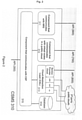
- Fig. 2 shows the CSMS 310 of Fig. 1 in greater detail.
- a first API 750 provides an interface of the CSMS 310 to a first component 312 of the CSMS 310 that communicates with virtual nodes in the public cloud 400.
- a second API 800 provides an interface to the service provider cloud component and to a cloud abstraction layer "CAL" 313, which enables access to the party public clouds like AWS, GCP, and the like.
- a third API 900 provides an interface to a third component 311 that communicates with the node registration system "NRS" 224. All those components are connected to a fourth component 315 that communicates with the CSP 300.
- the fourth component 315 is connected to a database 314 of the CSMS 310.
- Fig. 3a illustrates hardware components of the external cloud computing unit 210.
- the external cloud computing unit 210 features a CPU 211, memory 212, a disk storage 213 components with enough cycles and capacities for embedding a pre-installed software stack 220 and for installing additional applications.
- the external cloud computing unit 210 also shows an Ethernet port 214 for connecting to a home gateway router or switch.
- the external cloud computing unit 210 may have a WiFi interface 216 and/or a USB interfaces 215 for supporting wireless connectivity and storage extension.
- the Ethernet interface 214 is an essential part of the device since the user 100 must access a web front-end 226 of the Node Registration System (NRS) 224 of the public cloud 400 by means of the web front-end for the node registration.
- NRS Node Registration System
- the NRS 224 serves the purpose that only authorized external cloud computing units 210 can connect/register to the public cloud 400. After the registration an initial configuration process of the external cloud computing unit 210 is performed. After the successful initial configuration process, the network communication may be changed from the Ethernet interface 214 to the WiFi interface 216 if the external cloud computing unit 210 is equipped with the WiFi interface 216.
- Some methods allow the external cloud computing unit 210 to establish a connectivity to the home network over the WiFi interface 216 without a special human interaction such as keyboard and mouse utilization.
- the registration of the external cloud computing unit 210 may be performed by means of the WiFi interface 216 instead of the Ethernet interface 214, but the invention describes the process of setting-up the external cloud computing unit 210 based on the Ethernet interface 214.
- the external cloud computing unit 210 has a hardware push button 218 to operate re-configuration actions such as stop, restart or factory reset.
- the button 218 can trigger different actions based on the status of the device and the duration of the button push. For example, the external cloud computing unit 210 will turn on when the button 218 is pressed one time shortly if the machine is turned off, while the same action will restart the machine when the button 218 is pressed during its operation.
- a long press on the button 218, e.g. longer than five seconds, will initiate a safe stop of the external cloud computing unit 210.
- the external cloud computing unit 210 will initiate a factory reset process if the button is pressed, for example, longer than 10 seconds.
- the external cloud computing unit 210 may have two or more buttons for triggering different actions.
- the device can obtain supply of electric power by a USB port 217 or by an AC adapter 217 depending on the power consumption of the external cloud computing unit 210.
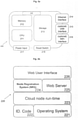
- Fig. 3b illustrates the software stack 220 that is required to be pre-installed within the external cloud computing unit 210.
- the pre-installed software stack 220 of the external cloud computing unit 210 comprises an operating system 221, an ID-Code 222 and a cloud node run-time 223.
- a run-time is a set of software that enables a computer system to create an environment for conducting specific functions. Therefore, in present case, the cloud run-time 223 enables the external cloud computing unit 210 to work as a cloud node. In other words, the run-time 223 is an enabler of virtualized computing and networking environments.
- a single physical machine can host multiple logical machines (i.e., virtual machines) or multiple independent applications and services (e.g., containers and pods) concurrently.
- a set of scripts or binary executables and a graphical web user interface 226 over a web server 225 are prepared for the configuration of the external cloud computing unit 210.
- the NRS 224 coordinates the node configuration process with the Cloud Service Management System (CSMS) 310 in the service provider's network 500.
- CSMS Cloud Service Management System
- the NRS 224, the Web Server and the Web User Interface may be modularized in virtualized machines or containers.
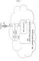
- Fig. 4 illustrates the set up process of the hybrid cloud system for the user 100.
- the user can establish a first set-up link 700 with the CSP 300 to start the set up process.
- a first set-up link 700 with the CSP 300 to start the set up process.
- he can provide information to the CSP 300 concerning his future hybrid cloud system "HCS" 50, like the location available bandwidth, etc.
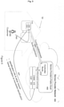
- Fig. 5 shows the installation and bootstrapping method of the external cloud computing unit 210 within the home network of the user.
- the user can connect the worker node 210 to his home gateway router 230.
- the web front-end 2266 he can start the setup process.
- the worker node 210 can transfer identification information and set-up request to the CSMS 310, in particular, a communication link to the API 900 can be the tunneled link 850 that uses the home gateway 230 to communicate with the Internet.
- the worker node 210 receives set up information from the CSMS 310 over the communication link after successful identification.
- the CSMS 310 adds the worker node 210 as an external worker node 210 to the cloud 400, which upgrades the public cloud 400.
- the public cloud 400 now comprises "public" working nodes 420 and external worker node 210.
- the CSMS 310 stores this information and distributes different tasks depending on if the node is a "public" working node 420 or a user associated external worker node 210.
- Fig. 6 shows the extension of the private cloud system of the user 100 to the public cloud system 400 of a service provider.
- the user 100 can specify a set of policy rules that allows the public cloud system 400 to outsource computational tasks of the public cloud 400 to the external worker node 210 if certain criteria are fulfilled. This leads efficiently to an extension the public cloud system 400.
- the controller node 410 can distribute computational tasks of the public worker nodes 420 the external worker node 210.
- a possible scenario can be that the user 100 is currently not using his external worker node 210. If the policy rules specify that computational tasks of the user 100 always have a higher priority than all the other computational tasks, this provides an efficient way of upgrading the public cloud system 400 while at the same time ensuring the full computational power of the external working node 210 to the user 100.
- Fig. 7 illustrates retrieving an application image from a repository of the service provider and its implementation on the external worker node 210.
- a first application repository 600 can be associated to the service provider network 500 and a second application repository 610 can be associated to the Internet, which basically means the 3 rd -party application repository.
- the applications can be downloaded to the worker node 210 by means of an application download link 970.
- Fig. 8 shows a flow diagram, which illustrates the implementation of the new external cloud computing unit 210 - which is also called the external worker node 210 - to the public cloud system of the service providers.
- Fig. 8 illustrates the process of the cluster creation.
- the user 100 creates his private cluster by registering to the HCS 50 at the Cloud Service Portal (CSP) 300 by starting a registration process 701.
- the registration process 701 the user 100 is authenticated and his user data is being stored.
- the registration process 701 can send an answer to the user 100 concerning his registration request, this includes sending data relating to the registration to the user 100.
- the CSP 300 is a web-based service front-end and provides human-friendly management interfaces in graphical form.
- the user 100 can create his private cluster through the CSP 300.
- the system can perform a check if the customer's membership is valid for the creation of the cluster in step 704.
- the Cloud Service Management System (CSMS) 310 creates a customer-dedicated controller node 410 in service the public cloud 400 of the service provider or within a 3rd-party public cloud and creates a unique cluster-id that is dedicated to a cluster .
- CSMS Cloud Service Management System
- the cluster-id can be a hashed text, human-friendly text name, or number for identifying a cluster across service provider's public cloud 400 and CSMS 310. More precisely, the cluster-id must be the unique identifier of clusters within the HCS 50.
- the CSMS 310 is a back-end management system and consists of various software components.
- the CSMS 310 has a set of scripts or executables that communicate with the public cloud 400 of the service provider, with 3rd-party public cloud services, with the user's dedicated nodes in public cloud systems 312, and with the NRS of a hardware node at user's premise 311.
- Cloud Abstraction Layer (CAL) 313 in CSMS 310 handles the communication with different public cloud systems.
- CAL 313 interprets HCS APIs to Cloud-specific APIs for different public cloud systems such as AWS and GCP.
- CSP 300 and CSMS 310 may be implemented in the same computer system/server or they can be implemented in different computer systems.
- CSP 300 can directly deliver the user's requests to the CSMS 310 through the dedicated APIs 350 and the internal communication methods such as a message bus or IPC (Inter-Process communication);
- CSP 300 and CSMS 310 communicate with each other through the dedicated APIs 350 and remote message transfer methods such as REST or RPC.
- the architecture of the HCS 50 assumes that service provider's public cloud 400 has its own cloud management system.
- the public cloud 400 communicates with the CSMS 310 with dedicated APIs.
- the user 100 manages the cluster through the CSP 300 by using a web browser on a computer or a mobile application created by the service provider.
- the customer must be authenticated with the credentials through CSP 300 in order to manage his cluster.
- the CSP 300 converts user's request into appropriate API calls and deliver them to the CSMS 310.
- the CSMS 310 communicates with the controller node 410 of user's cluster through dedicated APIs 750.
- Table 1 shows a set of example APIs 350 used for communication between CSMS 310 and CSP 300.
- Table 1 A subset of APIs between CSMS and CSP API Calls Description cluster_id createCluster(user_id) Creates a cluster for the customer with the given user_id. This API call returns a HCS-wide unique cluster_id on successful cluster creation.
- authenticateUser(user_id, user_password) Verifies the user with given user_id and user_password.
- the call authenticates the user if the verification is successful getClusterStatus(user_id) retrieves the status and information of the cluster that belongs to the user_id getNodes(user_id) retrieves the status and information of the nodes that belong to the user_id getNode(user_id, node_id) retrieves the status and information of the node that is associated to the given node_id getlnstalledServices(user_id) retrieves a list of installed applications and services within the cluster that belongs to the user_id getStatusOfService(user_id, node_id, svc_id) retrieves the status and information of an application or a service that is installed in a specific node of the cluster that belongs to the user_id getListOfAvailableServices(user_id) retrieves a list of applications that can be deployed within the cluster that belongs to the user_id deployService(user_id, node_id, app_
- Table 2 shows a set of example APIs between CSMS 310 and nodes in the public cloud 400
- Table 2 A subset of example APIs between CSMS 310 and nodes 410, 420 in the public cloud 400 API Calls Description initiate Tunnel (node_info) Orders the controller node 410 to initiate a tunnel towards a working node with the given note information getToken(cluster_id) Retrieves a token required to join the cluster that is associated with a given cluster_id deployService(node_id, app_url)
- Table 3 shows a set of example APIs 800 used for communication between the CSMS 310 and the management system of the public cloud 400.
- Table 3 A subset of APIs between CSMS 310 and the public cloud 400 management system API Calls Description node_id createControllerNode(cluster_id) Creates a virtual node within the cluster that is associated with the cluster_id. The virtual node will load an image that is pre-installed on the software stack required to be a controller node. This call returns a unique node_id on successful node creation.
- node_id createWorkerNode(cluster_id) Creates a virtual node within the cluster that is associated with the given cluster_id.
- the virtual node will pull an image that is pre-installed with the software stack required to be a worker node 220. This call returns a unique node_id on successful node creation.
- changeResourceNode(node_id, predefined_size) Increase or decrease the resources of the node to predefined size
- deleteNode(node_id) Delete a node that is associated with the given node_id getNode(node_id) retrieves the status and information of the node that is associated to the given node_id
- Table 4 shows a set of example APISs 900 used for the communication between the CSMS 310 and the BRS of the external node 210 in the home 200 of the user 100.
- Table 4 APIs 900 between CSMS 310 and NRS 224 API Calls Description, registerNode(code, user_id, user_password) NRS sends the unique hardware identification code of the external node 210 and credentials of the user to the CSMS for the authentication of the hardware and the user initiate Tunnel(controller_node_info) CSMS orders NRS to initiate a tunnel towards the controller node joinCluster(controller_node_info, token) CSMS orders NRS to join the cluster by using the controller note information and token issued by the controller node unregisterNode(code, user_id, user_passws) NRS sends the unique hardware identification code and the credentials of the user to the CSMS for removing the hardware node from the cluster safely notifyTunnelBreak(user_id, node_i
- Figure 9 illustrates the process of the registration of the external worker node 210 at the home 200 of the user 100.
- the user 100 purchases the external worker node 210 from the service provider in which the required software stack 220 is pre-installed.
- the software stack 220 includes a pre-installed service stack that includes NRS and web user interface 226 on a web server 225. These functions provide the user 100 with an easy installation of the external worker node 210.
- each purchased external worker node 210 has a unique identification code 222.
- the identification code 222 can be implemented by the service provider or be associated with the serial code of the external worker node 210 implemented by the hardware manufacturer. In any case, the identification code must be unique within service provider's cloud system 400.
- the user 100 For the registration of the external worker node 210, the user 100 connects the external worker node 210 to the home gateway router 230 with an Ethernet cable.
- the user 100 can access the web user interface of the external worker node 210 through a web browser of a computer connected to the same network. To do this, the user 100 can use the provider-given hostname instead of an IP address.
- the user 100 provides user credential (i.e., id and password) and the identification code of the external worker node 210 at step 651.
- the NRS 224 communicates with the CSMS 310 at step 901 and the CSMS 310 verifies the integrity of the user 100 and the external worker node 210 by comparing the provided credentials and identification code with stored information within the database 314 of the CSMS 310. If the integrity check succeeds steps 903 and 753 are executed, the CSMS 310 registers the external worker node 210 to the cluster of the user 100 and locks the identification code of external worker node 210 in the database 314.
- the user 100 For reconfiguring the external worker node 210, the user 100 must unlock the identification code 222 through a management page in the CSP 300. If the verification process fails at step 902, the CSMS 310 sends a failure message back to the NRS of the device and the user 100 is notified about the registration failure by means of the web browser.
- This configuration process can be implemented with existing protocols and mechanisms such as TR-069 and Netconf/Yang.
- the CSMS 310 sends the access and/or link establishing information to the external worker node 210 and the controller node 410 for establishing a tunnel 850 between those two devices in step 851.
- Different Tunneling methods are known to the person skilled in the art.
- the CSMS 310 also provides the external worker node 210 with a token of the controller node 410 that is required to join the cluster 400.
- the external worker node 210 joins the cluster 400 in step 852 by using the token received by the CSMS 310.
- the controller node 410 sends the status information to the CSMS 310 in step 754 and the CSMS 310 stores the information into the database 314.
- home network gateway of the user 100 does not have a static IP address and the Internet Service Provider (ISP) changes the public IP address of the home gateway router 230 periodically.
- ISP Internet Service Provider
- the established tunnel between the external worker node 210 and the controller node 410 in the public cloud 400 will break when the public IP address of the home gateway router 230 changes.
- the NRS 224 checks the status of the tunnel 850 periodically at step 853 and notifies CSMS 310 when the tunnel 850 is broken at step 904. Then, the CSMS 310 triggers the tunnel 850 reestablishment and cluster recovery.
- Fig. 10 illustrates the process of a cluster extension to the public cloud 400.
- the user 100 can extend the capacity of the cluster by purchasing a virtual machine 420 in the public cloud 400 of the service provider. In that case, the required software stack 220 is pre-installed in the virtual machine 420. Extending the capacity in the public cloud 400 is simpler than that in home 200 of the user 100 since it does not require any physical equipment. Indeed, the cloud service described in this invention can also operate without the external worker node 210 at the home 200 of the user 100. In that case, the use case scenario will be the same as known from conventional public cloud services.
- the user 100 For extending the capacity of the cluster of the public cloud 400 of the service provider, the user 100 needs to access the CSP 300 through a web browser or the mobile application provided by the service provider.
- the user 100 requires a successful authentication in step 706 to access the management page of the public cluster 400.
- the user 100 can request a new worker node 420 in the public cloud 400 of the service provider cloud in step 707.
- the user 100 can choose a worker node 420 from different resource variances.
- the CSMS 310 verifies the order of the user 100. For example, the CSMS 310 checks if the membership of the user 100 or credit is valid to purchase the requested (virtual) worker node 420.
- the CSMS 310 communicates with the management system of the public cloud 400 in step 803 and requests the creation of a new worker node 420 in step 803a.
- the public cloud 400 sends the information about the new worker node 420 in step 804 to the CSMS 310.
- the CSMS 310 communicates with NRS 224 of the new worker node 420 by using this information and provides the information of the controller node in step 755.
- the new worker node 420 joins the cluster 400 with the provided information in step 771.
- the controller node 410 notifies the CSMS 310 about the successful node extension in step 756 and the CSMS 310 stores all the information in the database 314.
- Figure 11 illustrates the process of the application installation in a worker node 210, 420.
- the CSMS 310 updates a list of services (i.e., a set of applications) and applications that can be installed in the cluster of the user 100 in step 951.
- the list of services and applications is shown as a web catalogue through the CSP 300 and the user 100 needs to be authenticated to see the list according to the steps 708-710.
- Each service or application on the list includes a detailed information such as capabilities, requirements (e.g., resources), target worker node (e.g., in-house node or public node), origin repository (e.g., service provider's repository or 3rd-party repository) and configuration detail.
- the user 100 requests for the installation of a service or an application by clicking a button on the catalogue in the CSP 300 in step 711. Then, the controller orders an appropriate worker node 420 to load and install the image from the repository, and to configure the service or application according to the predefined deployment policy in step 772. Once the application or the service is installed, the worker node 420 notifies the controller node 410 about the current resource status of the node in step 773 and the controller node collates the information from worker nodes 420 in the cluster 400 and notifies it to the CSMS 310 in step 758. The user 100 can check the status of the cluster 400 through the CSP 300 in step 712.
Landscapes
- Engineering & Computer Science (AREA)
- General Engineering & Computer Science (AREA)
- Signal Processing (AREA)
- Computing Systems (AREA)
- Computer Security & Cryptography (AREA)
- Computer Networks & Wireless Communication (AREA)
- Computer Hardware Design (AREA)
- Physics & Mathematics (AREA)
- Software Systems (AREA)
- Theoretical Computer Science (AREA)
- Mathematical Physics (AREA)
- General Physics & Mathematics (AREA)
- Computer And Data Communications (AREA)
- Data Exchanges In Wide-Area Networks (AREA)
Abstract
Description
- The invention relates to the technical field of cloud computing system, in particular the invention relates to techniques to extend public cloud computing systems to a home environment of a user and/or companies by using a dedicated external cloud computing unit and/or a dedicated arrangement of cloud computing entities.
- Due to the increasing size and number of digital content and the possibility to outsource computing power, cloud systems become more and more popular among Internet users. An additional advantage of cloud systems is that they can efficiently be upgraded to enhance their performance. Conventionally, if the user wanted to increase his storage or computing resources he had to upgrade his hardware, e.g. by buying a new computer. In the case of cloud computing systems, the user only needs a communication interface to the cloud computing system to benefit directly from hardware upgrades of the cloud computing system without the need to change his own computer. The computer of the user only needs to transfer data to the cloud computing system while the resources consuming computing tasks are executed on the cloud of the system itself.
- Internet users can subscribe to various services of a cloud service provider and use computing and networking resources over the Internet according to an agreement with the cloud service provider. This cloud service is commonly referred to as a public cloud service because basically everyone can use the service after signing a contract with the cloud service provider. Public cloud services offer nearly "unlimited" storage and computing power, and easy deployment of application services for their customers.
- Despite the advantages of the public cloud, there still remains some disadvantages. For example, the time it takes for the data to travel from the user to the public cloud system back and forth, the so-called round-trip time, is generally very large, which is still a remaining problem for latency-sensitive services and applications due to the propagation delay caused by the physical distance between a customer and a data center where the cloud service is operated. For example, Augmented Reality (AR) or Virtual Reality (VR) applications with ultra-high quality videos are considered as being latency-sensitive. Pre-downloading such high-volume media content at customer's devices is the most viable solution for improving the user experience.
- Another issue is that some services and content are intended to be accessible within the home network because databases of public cloud service providers are often targeted by cyber criminals. Hence, up to now there remains a security risk if the user uses public cloud services to store or to compute security sensitive data. Management applications of IoT (Internet of Things)-based home appliance devices are examples of those security sensitive application groups.
- Larger companies can benefit from cloud computing principles and maintaining a higher level of security by running their own cloud computing system within their home network. In addition, this reduces the latency issue. However, for small companies or home users such a "private" cloud computing system is often too expensive and requires a high level of system administration skills.
- A home server system could be a simpler solution than the private cloud system at customer's home. A home server system offers an easy installation of applications and comprehensive management over a web front-end or a mobile app for the customer, but the scope of services is typically limited to multimedia or traditional network applications specified by the system vendor. The availability of services in a home server system might be low if the customer wants to expose a part of services (e.g., a personal website or blog) to the public. Another problem of the home server system is that it is difficult to extend its resources. An upgrade of the system might not be possible regarding the system design or, if it is possible, the customer needs to replace a hardware component and to reconfigure the system.
- According to a first aspect of the invention an external worker node for the use in a home network environment of a user adapted to access a public cluster in the internet is described, the external worker node comprises
- a communication interface adapted to communicate with a communication network, in particular via a home gateway router;
- a computing unit adapted to perform calculation tasks, in particular calculation tasks of nodes in a computing cluster;
wherein the external worker node comprises
a pre-installed software stack, wherein the pre-installed software stack comprises - a node registration system "NRS" that is adapted to coordinate a registration process of the external worker node with a Cloud Service Management System "CSMS" of a public cluster of a network provider.
- This provides the advantage that the user can easily implement features of a public cluster into his secure home network in order to increase his computational resources. The user simply buys the external worker node of the provider of the public cluster, wherein the pre-installed software stack does the necessary registration, authentication steps in order to connect to other parts of the public cluster. The CSMS knows about all the worker nodes of the public cluster, including the external worker nodes, and is therefore able to efficiently distribute the computational tasks between them. Hence, in principle the external worker node is a plugin solution to extend or implement additional computing resources. The user can run safety relevant computational tasks on his external worker node without the risk that data can be stolen by transferring them from the user to the public cloud and back. In addition, latency critical computational tasks can be done because the time sending data packets forth and back is no longer necessary. However, the user still has in principle access to the other worker nodes in the public cloud and can use those computational resources for example for running safety critical computational tasks. This provides an easy way of a scalable computer environment. The term external is to be understood that the external worker node is being external with respect to the other nodes of the public cloud.
- In an embodiment, the pre-installed software stack comprises a security unit adapted to store an identification code "ID-code" of the external worker node.
- This provides the advantage that only verified and trusted external worker nodes can be put into operation by the user. To serve that purpose every ID-code is unique and pre-stored in a database of the
CSMS 310. - In an embodiment, the pre-installed software stack comprises a web-user-interface adapted to enable the communication of the user with the CSMS.
- This provides the user with a convenient way to enter his credentials or other necessary information to put the external worker node into operation. Especially, this can provide a convenient way of error management of the worker node if the user can send diagnostic information about the external worker node through the web-user-interface to the service provider of the public cloud.
- In an embodiment, the pre-installed software stack comprises cloud run time.
- The cloud run-time enables the external worker node to act as a node of the public cloud. In other words, the cloud run-time is an enabler of virtualized computing and networking environments.
- In an embodiment, the external worker node is adapted to share computational tasks with worker nodes of the public cluster.
- This provides the advantage, that the user can access our benefit from the computational resources of the other nodes in the public cloud. In addition, the public cloud has access to the external worker node in order to increase its own computational resources. Therefore, in principle all the worker nodes of the public cloud could be represented by external worker nodes at multiple users managed by a single CSMS of the network provider.
- In an embodiment, the external worker node is adapted to prefer computational requests of the user over all other computational requests from the public cluster.
- This provides the advantage that the user can share the computational resources of his home-based external working node with the public cluster and at the same time ensuring that his computational resources are only used if he does not need them.
- In an embodiment, the external worker node is adapted to establish a secure tunneled link with the public cluster.
- This provides the advantage of a secure data transfer between the external worker node and the public cluster. Implementation details of the tunnel can be stored in a security unit of the software stack by the service provider of the public cluster.
- According to a second aspect of the invention, a hybrid cloud system is provided, wherein the hybrid cloud system comprises
- a public cluster of a service provider configured to perform computational tasks of users, wherein the public cluster comprises
- ∘ worker nodes adapted to perform the computational tasks,
- ∘ a cloud service management system adapted to manage the worker nodes and to add new worker nodes and/or external worker node to the public cluster;
- a communication network adapted to establish communication links between the worker nodes and/or between the worker nodes and the CSMS;
- an external worker node as described above, wherein the external worker node exchanges data with the public cluster via the communication network.
- This provides the advantage of a very flexible and scalable hybrid cloud system that can integrate home-based external worker nodes as well as ordinary public nodes within one computational cluster managed by the CSMS. It combines the advantages of enhanced computational power for users with a safe computational environment that efficiently shields from cyber-attacks.
- In an embodiment, the external worker node is connected to the communication network via a home gateway router.
- This provides the advantage, that the external worker node can efficiently use existing resources within the home network of the user and that the firewall of the home gateway router serves as an additional security measure against cyber-attacks.
- In an embodiment, the hybrid cloud system comprises of multiple external worker nodes.
- This provides the advantage, that multiple users can benefit from the hybrid cloud system and that the hybrid cloud system can easily be extended with respect to computational power.
- In an embodiment, more than one or all multiple external worker nodes are associated to a single user.
- This is especially beneficial for companies that have a high computational power demand. They can in principle connect any number of external worker nodes to the public cluster and therefore perfectly match the actual computational demand.
- In an embodiment, the communication between the nodes, the CSMS and/or a cloud service portal are realized as application programming interfaces, which provides a convenient way to realize communication in a modular system.
- In an embodiment, a cloud abstraction layer of the CSMS translates requests of the user into various public cloud APIs. This provides the advantage, that the user does not need to know about the APIs, but that the cloud abstraction layer casts about the "translation" of the requests of the user.
- According to a third aspect of the invention, a method for setting up a hybrid cloud system as described above is provided, wherein the method comprises the following steps:
- Connecting an external worker node as described above to a communication network, wherein a public cluster is associated to the communication network;
- Starting a registration and authentication process of the external worker node at the CSMS;
- After successful registration of the external worker node adding the external worker node to the public cluster.
- In the following, preferred examples of the present invention are explained with reference to the accompanying figures
- Fig. 1:
- illustrates the overall architecture of the hybrid cloud system comprising a user's external cloud computing unit and public cloud nodes.
- Fig. 2:
- shows functional components of the cloud service management system of
Fig. 1 . - Fig. 3a:
- shows hardware components of the external cloud computing unit.
- Fig. 3b:
- shows a software stack of the cloud computing unit of
Fig. 3a . - Fig. 4:
- illustrates the set up process of the hybrid cloud system for a user.
- Fig. 5:
- shows the installation and bootstrapping method of the external cloud computing unit within the home network of the user.
- Fig. 6:
- shows the extension of a private cloud system of the user to a public cloud system of a service provider.
- Fig. 7
- illustrates retrieving an application image from a repository of the service provider and its implementation on the external cloud computing unit.
- Fig. 8:
- shows a flow diagram, which illustrates the implementation of a new external cloud computing unit to the public cloud system of the service providers.
- Fig. 9:
- shows flow diagram, which illustrates the implementation of the new external cloud computing unit by the user to the public cloud system.
- Fig. 10
- shows a flow diagram that illustrates the extension of resources of the cluster and features to the public cloud system of the service provider.
- Fig. 11
- shows a flow diagram that illustrates the implementation of an application to the cluster by the user.
- In the following, numerous features of the present invention are explained in detail on the basis of preferred embodiments. The present disclosure is not limited to the specifically named combinations of features. Rather the characteristics specified here can be combined arbitrarily to invention-conformal embodiments, if this is not expressly excluded in the following.
-
Fig. 1 illustrates the overall architecture of an inventivehybrid cloud system 50 comprising a user's externalcloud computing unit 210, which is also called auser worker node 210 or an externalcloud computing node 210, andpublic cloud nodes public cloud 400 of a service provider. The externalcloud computing unit 210 establish a communication link with ahome gateway router 230 get access to the Internet. Thehome gateway router 230 builds up acommunication link 850, in particular a tunneledcommunication link 850, with thepublic cloud 400 within theservice provider network 500. Application programming interfaces "API" 750, 800, 900 are established between a cloud service management system "CSMS" 310 and thepublic cloud 400. Outside of his home, the user has also the possibility to connect to thepublic cloud 400 by looking in to the cloud service portal "CSP" 300. - The architecture of the
network 500, dedicated workflows and APIs (application programming interface) of Hybrid Cloud Service (HCS) allow auser 100 to build his/her own cloud cluster comprised of one or multiple low-cost externalcloud computing units 210 in user's home 200 and virtualized public nodes 410,420 within thepublic cloud 400 of the service provider. - The provider of the HCS may operate its own
public cloud 400, but he can also create theprivate cloud 400 or a public cluster by using 3rd-party public cloud systems such as AWS (Amazon Web Service) or GCP (Google Cloud Platform). A cluster is a group of physical or logical computers that works as a single computer with aggregated computing resources. - The HCS architecture supports low latency and high security by placing services and applications in the external
cloud computing units 210 that is implemented in the home 200 of theuser 100 where the access is under the control of theuser 100, especially if theuser 100 uses a fixed line for his user equipment to communicate with the externalcloud computing unit 210. The system also supports scalability, cost-efficiency and flexibility with the capability of adding additional externalcloud computing units 210 dynamically in the home 200 of theuser 100 or to add additional working nodes to thepublic cloud 400. - In technical terms, a node represents a physical or logical computer in which a group of computing resources is available for hosting computer software or network services. This invention describes a physical computer as a
single hardware node 210, but the physical computer may contain multiple virtual nodes if the computer, in particular a server, supports a virtualization technology and is implemented with the corresponding virtualization software. -
Fig. 2 shows theCSMS 310 ofFig. 1 in greater detail. Afirst API 750 provides an interface of theCSMS 310 to afirst component 312 of theCSMS 310 that communicates with virtual nodes in thepublic cloud 400. Asecond API 800 provides an interface to the service provider cloud component and to a cloud abstraction layer "CAL" 313, which enables access to the party public clouds like AWS, GCP, and the like. Athird API 900 provides an interface to athird component 311 that communicates with the node registration system "NRS" 224. All those components are connected to afourth component 315 that communicates with theCSP 300. Thefourth component 315 is connected to adatabase 314 of theCSMS 310. By means of this architecture, the service provider can efficiently run hispublic cloud 400. -
Fig. 3a illustrates hardware components of the externalcloud computing unit 210. The externalcloud computing unit 210 features aCPU 211,memory 212, adisk storage 213 components with enough cycles and capacities for embedding apre-installed software stack 220 and for installing additional applications. The externalcloud computing unit 210 also shows anEthernet port 214 for connecting to a home gateway router or switch. In addition, the externalcloud computing unit 210 may have aWiFi interface 216 and/or a USB interfaces 215 for supporting wireless connectivity and storage extension. TheEthernet interface 214 is an essential part of the device since theuser 100 must access a web front-end 226 of the Node Registration System (NRS) 224 of thepublic cloud 400 by means of the web front-end for the node registration. TheNRS 224 serves the purpose that only authorized externalcloud computing units 210 can connect/register to thepublic cloud 400. After the registration an initial configuration process of the externalcloud computing unit 210 is performed. After the successful initial configuration process, the network communication may be changed from theEthernet interface 214 to theWiFi interface 216 if the externalcloud computing unit 210 is equipped with theWiFi interface 216. - Some methods allow the external
cloud computing unit 210 to establish a connectivity to the home network over theWiFi interface 216 without a special human interaction such as keyboard and mouse utilization. In that case, the registration of the externalcloud computing unit 210 may be performed by means of theWiFi interface 216 instead of theEthernet interface 214, but the invention describes the process of setting-up the externalcloud computing unit 210 based on theEthernet interface 214. - The external
cloud computing unit 210 has ahardware push button 218 to operate re-configuration actions such as stop, restart or factory reset. Thebutton 218 can trigger different actions based on the status of the device and the duration of the button push. For example, the externalcloud computing unit 210 will turn on when thebutton 218 is pressed one time shortly if the machine is turned off, while the same action will restart the machine when thebutton 218 is pressed during its operation. A long press on thebutton 218, e.g. longer than five seconds, will initiate a safe stop of the externalcloud computing unit 210. The externalcloud computing unit 210 will initiate a factory reset process if the button is pressed, for example, longer than 10 seconds. In order to avoid the accidental erase of present configurations of the device, one can implement complex push pattern for the factory reset such as long-press and short-press combinations. Another option to avoid an accidental factory reset could be making it hard to press thebutton 218 without a special tool such as a pinhole. The externalcloud computing unit 210 may have two or more buttons for triggering different actions. The device can obtain supply of electric power by aUSB port 217 or by anAC adapter 217 depending on the power consumption of the externalcloud computing unit 210. -
Fig. 3b illustrates thesoftware stack 220 that is required to be pre-installed within the externalcloud computing unit 210. Thepre-installed software stack 220 of the externalcloud computing unit 210 comprises anoperating system 221, an ID-Code 222 and a cloud node run-time 223. A run-time is a set of software that enables a computer system to create an environment for conducting specific functions. Therefore, in present case, the cloud run-time 223 enables the externalcloud computing unit 210 to work as a cloud node. In other words, the run-time 223 is an enabler of virtualized computing and networking environments. In a virtualized computing environment, a single physical machine can host multiple logical machines (i.e., virtual machines) or multiple independent applications and services (e.g., containers and pods) concurrently. On top of the run-time 223, a set of scripts or binary executables and a graphicalweb user interface 226 over aweb server 225 are prepared for the configuration of the externalcloud computing unit 210. When the user initiates the externalcloud computing node 210 configuration/registration process through the graphical web user interface of the externalcloud computing unit 210, theNRS 224 coordinates the node configuration process with the Cloud Service Management System (CSMS) 310 in the service provider'snetwork 500. TheNRS 224, the Web Server and the Web User Interface may be modularized in virtualized machines or containers. -
Fig. 4 illustrates the set up process of the hybrid cloud system for theuser 100. The user can establish a first set-uplink 700 with theCSP 300 to start the set up process. For example, he can provide information to theCSP 300 concerning his future hybrid cloud system "HCS" 50, like the location available bandwidth, etc. -
Fig. 5 shows the installation and bootstrapping method of the externalcloud computing unit 210 within the home network of the user. In afirst installation step 650, the user can connect theworker node 210 to hishome gateway router 230. By means of the web front-end 226, he can start the setup process. By means of thethird API 900, theworker node 210 can transfer identification information and set-up request to theCSMS 310, in particular, a communication link to theAPI 900 can be the tunneledlink 850 that uses thehome gateway 230 to communicate with the Internet. In return, theworker node 210 receives set up information from theCSMS 310 over the communication link after successful identification. After successful identification and registration, theCSMS 310 adds theworker node 210 as anexternal worker node 210 to thecloud 400, which upgrades thepublic cloud 400. Thepublic cloud 400 now comprises "public" workingnodes 420 andexternal worker node 210. TheCSMS 310 stores this information and distributes different tasks depending on if the node is a "public" workingnode 420 or a user associatedexternal worker node 210. -
Fig. 6 shows the extension of the private cloud system of theuser 100 to thepublic cloud system 400 of a service provider. Via the first set-uplink 700, theuser 100 can specify a set of policy rules that allows thepublic cloud system 400 to outsource computational tasks of thepublic cloud 400 to theexternal worker node 210 if certain criteria are fulfilled. This leads efficiently to an extension thepublic cloud system 400. Thecontroller node 410 can distribute computational tasks of thepublic worker nodes 420 theexternal worker node 210. A possible scenario can be that theuser 100 is currently not using hisexternal worker node 210. If the policy rules specify that computational tasks of theuser 100 always have a higher priority than all the other computational tasks, this provides an efficient way of upgrading thepublic cloud system 400 while at the same time ensuring the full computational power of the external workingnode 210 to theuser 100. -
Fig. 7 illustrates retrieving an application image from a repository of the service provider and its implementation on theexternal worker node 210. This offers the advantage that theuser 100 can benefit from already existing applications and that he can run those applications in a safe environment on hisexternal worker node 210. Afirst application repository 600 can be associated to theservice provider network 500 and asecond application repository 610 can be associated to the Internet, which basically means the 3rd-party application repository. The applications can be downloaded to theworker node 210 by means of anapplication download link 970. -
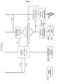
Fig. 8 shows a flow diagram, which illustrates the implementation of the new external cloud computing unit 210 - which is also called the external worker node 210 - to the public cloud system of the service providers. - Hence,
Fig. 8 illustrates the process of the cluster creation. Theuser 100 creates his private cluster by registering to theHCS 50 at the Cloud Service Portal (CSP) 300 by starting aregistration process 701. In theregistration process 701 theuser 100 is authenticated and his user data is being stored. Instep 702, theregistration process 701 can send an answer to theuser 100 concerning his registration request, this includes sending data relating to the registration to theuser 100. - The
CSP 300 is a web-based service front-end and provides human-friendly management interfaces in graphical form. After a successful registration, theuser 100 can create his private cluster through theCSP 300. The system can perform a check if the customer's membership is valid for the creation of the cluster instep 704. After asuccessful node creation 801 the process continues. On thecreation request 703 of theuser 100, the Cloud Service Management System (CSMS) 310 creates a customer-dedicatedcontroller node 410 in service thepublic cloud 400 of the service provider or within a 3rd-party public cloud and creates a unique cluster-id that is dedicated to a cluster . The cluster-id can be a hashed text, human-friendly text name, or number for identifying a cluster across service provider'spublic cloud 400 andCSMS 310. More precisely, the cluster-id must be the unique identifier of clusters within theHCS 50. - The
CSMS 310 is a back-end management system and consists of various software components. For example, theCSMS 310 has a set of scripts or executables that communicate with thepublic cloud 400 of the service provider, with 3rd-party public cloud services, with the user's dedicated nodes inpublic cloud systems 312, and with the NRS of a hardware node at user'spremise 311. Cloud Abstraction Layer (CAL) 313 inCSMS 310 handles the communication with different public cloud systems.CAL 313 interprets HCS APIs to Cloud-specific APIs for different public cloud systems such as AWS and GCP. - Another important component of
CSMS 310 is adatabase 314 that keeps the state of the user's cluster and information required for the user authentication.CSP 300 andCSMS 310 may be implemented in the same computer system/server or they can be implemented in different computer systems. - In the former case,
CSP 300 can directly deliver the user's requests to theCSMS 310 through the dedicatedAPIs 350 and the internal communication methods such as a message bus or IPC (Inter-Process communication); - For the latter case,
CSP 300 andCSMS 310 communicate with each other through the dedicatedAPIs 350 and remote message transfer methods such as REST or RPC. - The architecture of the
HCS 50 assumes that service provider'spublic cloud 400 has its own cloud management system. Thepublic cloud 400 communicates with theCSMS 310 with dedicated APIs. Theuser 100 manages the cluster through theCSP 300 by using a web browser on a computer or a mobile application created by the service provider. The customer must be authenticated with the credentials throughCSP 300 in order to manage his cluster. TheCSP 300 converts user's request into appropriate API calls and deliver them to theCSMS 310. TheCSMS 310 communicates with thecontroller node 410 of user's cluster through dedicatedAPIs 750. - One can implement the APIs in any variety of formats, methods and languages such as XML, JSON, REST, RPC, C++, C#, Java, Java Script, Ruby, Python, and so on. Table 1 shows a set of
example APIs 350 used for communication betweenCSMS 310 andCSP 300.Table 1 A subset of APIs between CSMS and CSP API Calls Description cluster_id createCluster(user_id) Creates a cluster for the customer with the given user_id. This API call returns a HCS-wide unique cluster_id on successful cluster creation. authenticateUser(user_id, user_password) Verifies the user with given user_id and user_password. The call authenticates the user if the verification is successful getClusterStatus(user_id) Retrieves the status and information of the cluster that belongs to the user_id getNodes(user_id) Retrieves the status and information of the nodes that belong to the user_id getNode(user_id, node_id) Retrieves the status and information of the node that is associated to the given node_id getlnstalledServices(user_id) Retrieves a list of installed applications and services within the cluster that belongs to the user_id getStatusOfService(user_id, node_id, svc_id) Retrieves the status and information of an application or a service that is installed in a specific node of the cluster that belongs to the user_id getListOfAvailableServices(user_id) Retrieves a list of applications that can be deployed within the cluster that belongs to the user_id deployService(user_id, node_id, app_id) Installs the application that has an app_id to a specific node of the cluster that belongs to the user_id removeService(user_id, node_id, svc_id) Removes the application that has an svc_id from the specific node of the cluster that belongs to the user_id moveService(user_id, node_id_1, node_id_2, svc_id) Moves an installed application or service from one node (node_id_1) to another node (node_id_2) createNewNode(user_id) Creates a new node in the public cloud and adds it to the cluster of the user unlockDevice(user_id, node_id) Change the status of a hardware device at user's home from a locked status to an unlocked status so that the hardware can be reinitialized by the user - Table 2 shows a set of example APIs between
CSMS 310 and nodes in thepublic cloud 400Table 2 A subset of example APIs between CSMS 310 andnodes public cloud 400API Calls Description initiate Tunnel (node_info) Orders the controller node 410 to initiate a tunnel towards a working node with the given note informationgetToken(cluster_id) Retrieves a token required to join the cluster that is associated with a given cluster_id deployService(node_id, app_url) Orders the controller node to install an application to the specified node that has the given node_id removeService(node_id, svc_id) Orders the controller node to remove the installed application or service from the node moveService(node_id_1, node_id_2,svc_id) Orders the controller node to move the installed application or service from one node (node_id_1) to another node (node_id_2) getNodeInfo(node_id) Retrieves the status and information of the node that is associated to the given node_id - Table 3 shows a set of
example APIs 800 used for communication between theCSMS 310 and the management system of thepublic cloud 400.Table 3 A subset of APIs between CSMS 310 and thepublic cloud 400 management systemAPI Calls Description node_id createControllerNode(cluster_id) Creates a virtual node within the cluster that is associated with the cluster_id. The virtual node will load an image that is pre-installed on the software stack required to be a controller node. This call returns a unique node_id on successful node creation. node_id createWorkerNode(cluster_id) Creates a virtual node within the cluster that is associated with the given cluster_id. The virtual node will pull an image that is pre-installed with the software stack required to be a worker node 220. This call returns a unique node_id on successful node creation.changeResourceNode(node_id, predefined_size) Increase or decrease the resources of the node to predefined size deleteNode(node_id) Delete a node that is associated with the given node_id getNode(node_id) Retrieves the status and information of the node that is associated to the given node_id - Table 4 shows a set of
example APISs 900 used for the communication between theCSMS 310 and the BRS of theexternal node 210 in the home 200 of theuser 100.Table 4 APIs 900 betweenCSMS 310 andNRS 224API Calls Description, registerNode(code, user_id, user_password) NRS sends the unique hardware identification code of the external node 210 and credentials of the user to the CSMS for the authentication of the hardware and the userinitiate Tunnel(controller_node_info) CSMS orders NRS to initiate a tunnel towards the controller node joinCluster(controller_node_info, token) CSMS orders NRS to join the cluster by using the controller note information and token issued by the controller node unregisterNode(code, user_id, user_passws) NRS sends the unique hardware identification code and the credentials of the user to the CSMS for removing the hardware node from the cluster safely notifyTunnelBreak(user_id, node_id) NRS sends a notification to the CSMS about the status of the broken tunnel -
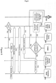
Figure 9 illustrates the process of the registration of theexternal worker node 210 at the home 200 of theuser 100. To extend thepublic cluster 400 to the home 200 of theuser 100, theuser 100 purchases theexternal worker node 210 from the service provider in which the requiredsoftware stack 220 is pre-installed. Thesoftware stack 220 includes a pre-installed service stack that includes NRS andweb user interface 226 on aweb server 225. These functions provide theuser 100 with an easy installation of theexternal worker node 210. For supporting the easy installation and theexternal worker node 210 registration, each purchasedexternal worker node 210 has aunique identification code 222. Theidentification code 222 can be implemented by the service provider or be associated with the serial code of theexternal worker node 210 implemented by the hardware manufacturer. In any case, the identification code must be unique within service provider'scloud system 400. - For the registration of the
external worker node 210, theuser 100 connects theexternal worker node 210 to thehome gateway router 230 with an Ethernet cable. Theuser 100 can access the web user interface of theexternal worker node 210 through a web browser of a computer connected to the same network. To do this, theuser 100 can use the provider-given hostname instead of an IP address. Theuser 100 provides user credential (i.e., id and password) and the identification code of theexternal worker node 210 atstep 651. TheNRS 224 communicates with theCSMS 310 atstep 901 and theCSMS 310 verifies the integrity of theuser 100 and theexternal worker node 210 by comparing the provided credentials and identification code with stored information within thedatabase 314 of theCSMS 310. If the integrity check succeedssteps CSMS 310 registers theexternal worker node 210 to the cluster of theuser 100 and locks the identification code ofexternal worker node 210 in thedatabase 314. - For reconfiguring the
external worker node 210, theuser 100 must unlock theidentification code 222 through a management page in theCSP 300. If the verification process fails atstep 902, theCSMS 310 sends a failure message back to the NRS of the device and theuser 100 is notified about the registration failure by means of the web browser. This configuration process can be implemented with existing protocols and mechanisms such as TR-069 and Netconf/Yang. - Once the
external worker node 210 is registered as a worker node of thecluster 400, theCSMS 310 sends the access and/or link establishing information to theexternal worker node 210 and thecontroller node 410 for establishing atunnel 850 between those two devices instep 851. Different Tunneling methods are known to the person skilled in the art. TheCSMS 310 also provides theexternal worker node 210 with a token of thecontroller node 410 that is required to join thecluster 400. Once thetunnel 850 is established, theexternal worker node 210 joins thecluster 400 instep 852 by using the token received by theCSMS 310. After the joining process is complete, thecontroller node 410 sends the status information to theCSMS 310 instep 754 and theCSMS 310 stores the information into thedatabase 314. - It is common that home network gateway of the
user 100 does not have a static IP address and the Internet Service Provider (ISP) changes the public IP address of thehome gateway router 230 periodically. The established tunnel between theexternal worker node 210 and thecontroller node 410 in thepublic cloud 400 will break when the public IP address of thehome gateway router 230 changes. TheNRS 224 checks the status of thetunnel 850 periodically atstep 853 and notifiesCSMS 310 when thetunnel 850 is broken atstep 904. Then, theCSMS 310 triggers thetunnel 850 reestablishment and cluster recovery. -
Fig. 10 illustrates the process of a cluster extension to thepublic cloud 400. Theuser 100 can extend the capacity of the cluster by purchasing avirtual machine 420 in thepublic cloud 400 of the service provider. In that case, the requiredsoftware stack 220 is pre-installed in thevirtual machine 420. Extending the capacity in thepublic cloud 400 is simpler than that in home 200 of theuser 100 since it does not require any physical equipment. Indeed, the cloud service described in this invention can also operate without theexternal worker node 210 at the home 200 of theuser 100. In that case, the use case scenario will be the same as known from conventional public cloud services. - For extending the capacity of the cluster of the
public cloud 400 of the service provider, theuser 100 needs to access theCSP 300 through a web browser or the mobile application provided by the service provider. Theuser 100 requires a successful authentication instep 706 to access the management page of thepublic cluster 400. Once theuser 100 has access to the management page, theuser 100 can request anew worker node 420 in thepublic cloud 400 of the service provider cloud instep 707. Theuser 100 can choose aworker node 420 from different resource variances. Then, theCSMS 310 verifies the order of theuser 100. For example, theCSMS 310 checks if the membership of theuser 100 or credit is valid to purchase the requested (virtual)worker node 420. If the verification is successful, theCSMS 310 communicates with the management system of thepublic cloud 400 instep 803 and requests the creation of anew worker node 420 instep 803a. When the creation is successful, thepublic cloud 400 sends the information about thenew worker node 420 instep 804 to theCSMS 310. TheCSMS 310 communicates withNRS 224 of thenew worker node 420 by using this information and provides the information of the controller node instep 755. Thenew worker node 420 joins thecluster 400 with the provided information instep 771. Finally, thecontroller node 410 notifies theCSMS 310 about the successful node extension instep 756 and theCSMS 310 stores all the information in thedatabase 314. -
Figure 11 illustrates the process of the application installation in aworker node CSMS 310 updates a list of services (i.e., a set of applications) and applications that can be installed in the cluster of theuser 100 instep 951. The list of services and applications is shown as a web catalogue through theCSP 300 and theuser 100 needs to be authenticated to see the list according to the steps 708-710. Each service or application on the list includes a detailed information such as capabilities, requirements (e.g., resources), target worker node (e.g., in-house node or public node), origin repository (e.g., service provider's repository or 3rd-party repository) and configuration detail. Theuser 100 requests for the installation of a service or an application by clicking a button on the catalogue in theCSP 300 instep 711. Then, the controller orders anappropriate worker node 420 to load and install the image from the repository, and to configure the service or application according to the predefined deployment policy instep 772. Once the application or the service is installed, theworker node 420 notifies thecontroller node 410 about the current resource status of the node instep 773 and the controller node collates the information fromworker nodes 420 in thecluster 400 and notifies it to theCSMS 310 instep 758. Theuser 100 can check the status of thecluster 400 through theCSP 300 instep 712.
Claims (14)
- External worker node for the use in a home network environment of a user adapted to access a public cluster in the internet, the external worker node (210) comprisesa communication interface (214, 215, 216) adapted to communicate with a communication network (500), in particular via a home gateway router (230);a computing unit (211, 212, 213) adapted to perform calculation tasks,characterized in that
the external worker node (210) comprises
a pre-installed software stack, wherein the pre-installed software stack comprises
a node registration system "NRS" (224) that is adapted to coordinate a registration process of the external worker node (210) with a Cloud Service Management System "CSMS" (310) of a public cluster (400) of a network provider. - The external worker node of claim 1, wherein the pre-installed software stack comprises a security unit adapted to store an identification code "ID-code" (222) of the external worker node (210).
- The external worker node of any of claims, wherein the pre-installed software stack comprises a web-user-interface adapted to enable the communication of the user (100) with the CSMS (310).
- The external worker node of any of claims, wherein the pre-installed software stack comprises cloud run-time (223).
- The external worker node of any of claims, wherein the external worker node (210) is adapted to share computational tasks with worker nodes (420) of the public cluster (400).
- The external worker node of any of claims, wherein the external worker node (210) is adapted to prefer computational requests of the user (100) over all other computational requests from the public cluster.
- The external worker node of any of claims, wherein the external worker node is adapted to establish a secure tunneled link (850) with the public cluster (400).
- A hybrid cloud system comprising• a public cluster of a service provider configured to perform computational tasks of users, wherein the public cluster comprises∘ worker nodes (420) adapted to perform the computational tasks,∘ a cloud service management system (310) adapted to manage the worker nodes and to add new worker nodes and/or external worker node to the public cluster (400);• a communication network (500) adapted to establish communication links between the worker nodes (420) and/or between the worker nodes (420) and the CSMS (310);• an external worker node (210) according to any of the claims 1-7, wherein the external worker node exchanges data with the public cluster (400) via the communication network (500).
- The hybrid cloud system of claim 8, wherein the external worker node is connected to the communication network (500) via a home gateway router (230).
- The hybrid cloud system of one of the claims 8 - 9, wherein hybrid cloud system comprises multiple external worker nodes (210).
- The hybrid cloud system of one of the claim 10, wherein all multiple external worker nodes (210) are associated to a single user (100).
- The hybrid cloud system of one of the claims 8 - 11, wherein the communication between the nodes (210, 420), the CSMS (310) and/or a cloud service portal (300) are realized as application programming interfaces.
- The hybrid cloud system of one of the claims 8 - 12, wherein a cloud abstraction layer of the CSMS (310) translates requests of the user (100) into various public cloud APIs.
- A Method for setting up a hybrid cloud system according to any of the claims 8 - 13 comprising the following steps:• Connecting an external worker node (210) according to any of the claims 1- 7 to a communication network (500), wherein a public cluster is associated to the communication network;• Starting a registration and authentication process of the external worker node (210) at the CSMS (310);• After successful registration of the external worker node (210) adding the external worker node (210) to the public cluster (400).
Priority Applications (1)
| Application Number | Priority Date | Filing Date | Title |
|---|---|---|---|
| EP20196603.3A EP3972214B1 (en) | 2020-09-17 | 2020-09-17 | Techniques to extend public cloud computing systems to a home of a user |
Applications Claiming Priority (1)
| Application Number | Priority Date | Filing Date | Title |
|---|---|---|---|
| EP20196603.3A EP3972214B1 (en) | 2020-09-17 | 2020-09-17 | Techniques to extend public cloud computing systems to a home of a user |
Publications (2)
| Publication Number | Publication Date |
|---|---|
| EP3972214A1 true EP3972214A1 (en) | 2022-03-23 |
| EP3972214B1 EP3972214B1 (en) | 2024-07-17 |
Family
ID=72560420
Family Applications (1)
| Application Number | Title | Priority Date | Filing Date |
|---|---|---|---|
| EP20196603.3A Active EP3972214B1 (en) | 2020-09-17 | 2020-09-17 | Techniques to extend public cloud computing systems to a home of a user |
Country Status (1)
| Country | Link |
|---|---|
| EP (1) | EP3972214B1 (en) |
Cited By (1)
| Publication number | Priority date | Publication date | Assignee | Title |
|---|---|---|---|---|
| CN114500120A (en) * | 2022-04-15 | 2022-05-13 | 阿里巴巴(中国)有限公司 | A public cloud expansion method, device, system and storage medium |
Citations (2)
| Publication number | Priority date | Publication date | Assignee | Title |
|---|---|---|---|---|
| CN110545397A (en) * | 2018-05-28 | 2019-12-06 | 中国移动通信有限公司研究院 | A community intelligent management method, equipment, medium and system |
| CN111027713A (en) * | 2019-12-10 | 2020-04-17 | 支付宝(杭州)信息技术有限公司 | Shared machine learning system and method |
-
2020
- 2020-09-17 EP EP20196603.3A patent/EP3972214B1/en active Active
Patent Citations (2)
| Publication number | Priority date | Publication date | Assignee | Title |
|---|---|---|---|---|
| CN110545397A (en) * | 2018-05-28 | 2019-12-06 | 中国移动通信有限公司研究院 | A community intelligent management method, equipment, medium and system |
| CN111027713A (en) * | 2019-12-10 | 2020-04-17 | 支付宝(杭州)信息技术有限公司 | Shared machine learning system and method |
Cited By (2)
| Publication number | Priority date | Publication date | Assignee | Title |
|---|---|---|---|---|
| CN114500120A (en) * | 2022-04-15 | 2022-05-13 | 阿里巴巴(中国)有限公司 | A public cloud expansion method, device, system and storage medium |
| WO2023197942A1 (en) * | 2022-04-15 | 2023-10-19 | 阿里巴巴(中国)有限公司 | Public cloud extension method, device, system and storage medium |
Also Published As
| Publication number | Publication date |
|---|---|
| EP3972214B1 (en) | 2024-07-17 |
Similar Documents
| Publication | Publication Date | Title |
|---|---|---|
| CN112035215B (en) | Node autonomy method, system, device and electronic equipment for node cluster | |
| US10827008B2 (en) | Integrated user interface for consuming services across different distributed networks | |
| US9560037B2 (en) | Integrated APIs and UIs for consuming services across different distributed networks | |
| CN107577516B (en) | Virtual machine password reset method, device and system | |
| KR101507919B1 (en) | Method and apparatus for virtual desktop service | |
| JP6181185B2 (en) | LDAP-based multi-customer in-cloud identity management system | |
| US20190207812A1 (en) | Hybrid cloud network configuration management | |
| JP6190949B2 (en) | Automatic configuration of access to virtual infrastructure manager by virtual network function manager | |
| US9021005B2 (en) | System and method to provide remote device management for mobile virtualized platforms | |
| CN101714996B (en) | Authentication system and method based on peer-to-peer computing network | |
| CN120035976A (en) | Authorization framework in multi-cloud infrastructure | |
| US10645172B1 (en) | Socket tunneling connections in a service provider environment | |
| US20100257261A1 (en) | System and method of device-to-server registration | |
| US9544358B2 (en) | Providing near real-time device representation to applications and services | |
| US12341776B2 (en) | Service to service communication and authentication via a central network mesh | |
| WO2012071907A1 (en) | Method and system for hosting desktop virtualized terminal | |
| CN121794945A (en) | Token exchange service | |
| WO2025034881A1 (en) | Authenticating certificate bundles with asymmetric keys | |
| CN121399584A (en) | Scalable hub and spoke topology for routing using compute instances | |
| EP3972214B1 (en) | Techniques to extend public cloud computing systems to a home of a user | |
| CN117395131A (en) | Abnormality notification method and device, electronic equipment and storage medium | |
| US20230344815A1 (en) | End-point instance indexing and owner pop selection in gateway service ticketing | |
| US20220038422A1 (en) | Authentication and firewall enforcement for internet of things (iot) devices | |
| WO2025090352A1 (en) | Provisioning hosts with operator accounts for use by clients to access target resources | |
| US12407678B2 (en) | Security schema for secure device onboarding |
Legal Events
| Date | Code | Title | Description |
|---|---|---|---|
| PUAI | Public reference made under article 153(3) epc to a published international application that has entered the european phase |
Free format text: ORIGINAL CODE: 0009012 |
|
| STAA | Information on the status of an ep patent application or granted ep patent |
Free format text: STATUS: THE APPLICATION HAS BEEN PUBLISHED |
|
| AK | Designated contracting states |
Kind code of ref document: A1 Designated state(s): AL AT BE BG CH CY CZ DE DK EE ES FI FR GB GR HR HU IE IS IT LI LT LU LV MC MK MT NL NO PL PT RO RS SE SI SK SM TR |
|
| STAA | Information on the status of an ep patent application or granted ep patent |
Free format text: STATUS: REQUEST FOR EXAMINATION WAS MADE |
|
| 17P | Request for examination filed |
Effective date: 20220727 |
|
| RBV | Designated contracting states (corrected) |
Designated state(s): AL AT BE BG CH CY CZ DE DK EE ES FI FR GB GR HR HU IE IS IT LI LT LU LV MC MK MT NL NO PL PT RO RS SE SI SK SM TR |
|
| REG | Reference to a national code |
Ref country code: DE Ref legal event code: R079 Free format text: PREVIOUS MAIN CLASS: H04L0029060000 Ipc: G06F0009500000 Ref country code: DE Ref legal event code: R079 Ref document number: 602020034008 Country of ref document: DE Free format text: PREVIOUS MAIN CLASS: H04L0029060000 Ipc: G06F0009500000 |
|
| GRAP | Despatch of communication of intention to grant a patent |
Free format text: ORIGINAL CODE: EPIDOSNIGR1 |
|
| STAA | Information on the status of an ep patent application or granted ep patent |
Free format text: STATUS: GRANT OF PATENT IS INTENDED |
|
| RIC1 | Information provided on ipc code assigned before grant |
Ipc: H04L 9/40 20220101ALI20240321BHEP Ipc: G06F 9/46 20060101ALI20240321BHEP Ipc: G06F 9/50 20060101AFI20240321BHEP |
|
| INTG | Intention to grant announced |
Effective date: 20240418 |
|
| GRAS | Grant fee paid |
Free format text: ORIGINAL CODE: EPIDOSNIGR3 |
|
| GRAA | (expected) grant |
Free format text: ORIGINAL CODE: 0009210 |
|
| STAA | Information on the status of an ep patent application or granted ep patent |
Free format text: STATUS: THE PATENT HAS BEEN GRANTED |
|
| AK | Designated contracting states |
Kind code of ref document: B1 Designated state(s): AL AT BE BG CH CY CZ DE DK EE ES FI FR GB GR HR HU IE IS IT LI LT LU LV MC MK MT NL NO PL PT RO RS SE SI SK SM TR |
|
| REG | Reference to a national code |
Ref country code: CH Ref legal event code: EP |
|
| REG | Reference to a national code |
Ref country code: DE Ref legal event code: R096 Ref document number: 602020034008 Country of ref document: DE |
|
| REG | Reference to a national code |
Ref country code: IE Ref legal event code: FG4D |
|
| REG | Reference to a national code |
Ref country code: LT Ref legal event code: MG9D |
|
| REG | Reference to a national code |
Ref country code: NL Ref legal event code: MP Effective date: 20240717 |
|
| PG25 | Lapsed in a contracting state [announced via postgrant information from national office to epo] |
Ref country code: PT Free format text: LAPSE BECAUSE OF FAILURE TO SUBMIT A TRANSLATION OF THE DESCRIPTION OR TO PAY THE FEE WITHIN THE PRESCRIBED TIME-LIMIT Effective date: 20241118 |
|
| REG | Reference to a national code |
Ref country code: AT Ref legal event code: MK05 Ref document number: 1704785 Country of ref document: AT Kind code of ref document: T Effective date: 20240717 |
|
| PG25 | Lapsed in a contracting state [announced via postgrant information from national office to epo] |
Ref country code: NL Free format text: LAPSE BECAUSE OF FAILURE TO SUBMIT A TRANSLATION OF THE DESCRIPTION OR TO PAY THE FEE WITHIN THE PRESCRIBED TIME-LIMIT Effective date: 20240717 |
|
| PG25 | Lapsed in a contracting state [announced via postgrant information from national office to epo] |
Ref country code: PT Free format text: LAPSE BECAUSE OF FAILURE TO SUBMIT A TRANSLATION OF THE DESCRIPTION OR TO PAY THE FEE WITHIN THE PRESCRIBED TIME-LIMIT Effective date: 20241118 Ref country code: NL Free format text: LAPSE BECAUSE OF FAILURE TO SUBMIT A TRANSLATION OF THE DESCRIPTION OR TO PAY THE FEE WITHIN THE PRESCRIBED TIME-LIMIT Effective date: 20240717 |
|
| PG25 | Lapsed in a contracting state [announced via postgrant information from national office to epo] |
Ref country code: NO Free format text: LAPSE BECAUSE OF FAILURE TO SUBMIT A TRANSLATION OF THE DESCRIPTION OR TO PAY THE FEE WITHIN THE PRESCRIBED TIME-LIMIT Effective date: 20241017 |
|
| PG25 | Lapsed in a contracting state [announced via postgrant information from national office to epo] |
Ref country code: FI Free format text: LAPSE BECAUSE OF FAILURE TO SUBMIT A TRANSLATION OF THE DESCRIPTION OR TO PAY THE FEE WITHIN THE PRESCRIBED TIME-LIMIT Effective date: 20240717 Ref country code: GR Free format text: LAPSE BECAUSE OF FAILURE TO SUBMIT A TRANSLATION OF THE DESCRIPTION OR TO PAY THE FEE WITHIN THE PRESCRIBED TIME-LIMIT Effective date: 20241018 Ref country code: PL Free format text: LAPSE BECAUSE OF FAILURE TO SUBMIT A TRANSLATION OF THE DESCRIPTION OR TO PAY THE FEE WITHIN THE PRESCRIBED TIME-LIMIT Effective date: 20240717 |
|
| PG25 | Lapsed in a contracting state [announced via postgrant information from national office to epo] |
Ref country code: BG Free format text: LAPSE BECAUSE OF FAILURE TO SUBMIT A TRANSLATION OF THE DESCRIPTION OR TO PAY THE FEE WITHIN THE PRESCRIBED TIME-LIMIT Effective date: 20240717 |
|
| PG25 | Lapsed in a contracting state [announced via postgrant information from national office to epo] |
Ref country code: LV Free format text: LAPSE BECAUSE OF FAILURE TO SUBMIT A TRANSLATION OF THE DESCRIPTION OR TO PAY THE FEE WITHIN THE PRESCRIBED TIME-LIMIT Effective date: 20240717 |
|
| PG25 | Lapsed in a contracting state [announced via postgrant information from national office to epo] |
Ref country code: IS Free format text: LAPSE BECAUSE OF FAILURE TO SUBMIT A TRANSLATION OF THE DESCRIPTION OR TO PAY THE FEE WITHIN THE PRESCRIBED TIME-LIMIT Effective date: 20241117 Ref country code: AT Free format text: LAPSE BECAUSE OF FAILURE TO SUBMIT A TRANSLATION OF THE DESCRIPTION OR TO PAY THE FEE WITHIN THE PRESCRIBED TIME-LIMIT Effective date: 20240717 |
|
| PG25 | Lapsed in a contracting state [announced via postgrant information from national office to epo] |
Ref country code: HR Free format text: LAPSE BECAUSE OF FAILURE TO SUBMIT A TRANSLATION OF THE DESCRIPTION OR TO PAY THE FEE WITHIN THE PRESCRIBED TIME-LIMIT Effective date: 20240717 |
|
| PG25 | Lapsed in a contracting state [announced via postgrant information from national office to epo] |
Ref country code: ES Free format text: LAPSE BECAUSE OF FAILURE TO SUBMIT A TRANSLATION OF THE DESCRIPTION OR TO PAY THE FEE WITHIN THE PRESCRIBED TIME-LIMIT Effective date: 20240717 Ref country code: RS Free format text: LAPSE BECAUSE OF FAILURE TO SUBMIT A TRANSLATION OF THE DESCRIPTION OR TO PAY THE FEE WITHIN THE PRESCRIBED TIME-LIMIT Effective date: 20241017 |
|
| PG25 | Lapsed in a contracting state [announced via postgrant information from national office to epo] |
Ref country code: RS Free format text: LAPSE BECAUSE OF FAILURE TO SUBMIT A TRANSLATION OF THE DESCRIPTION OR TO PAY THE FEE WITHIN THE PRESCRIBED TIME-LIMIT Effective date: 20241017 Ref country code: PL Free format text: LAPSE BECAUSE OF FAILURE TO SUBMIT A TRANSLATION OF THE DESCRIPTION OR TO PAY THE FEE WITHIN THE PRESCRIBED TIME-LIMIT Effective date: 20240717 Ref country code: NO Free format text: LAPSE BECAUSE OF FAILURE TO SUBMIT A TRANSLATION OF THE DESCRIPTION OR TO PAY THE FEE WITHIN THE PRESCRIBED TIME-LIMIT Effective date: 20241017 Ref country code: LV Free format text: LAPSE BECAUSE OF FAILURE TO SUBMIT A TRANSLATION OF THE DESCRIPTION OR TO PAY THE FEE WITHIN THE PRESCRIBED TIME-LIMIT Effective date: 20240717 Ref country code: IS Free format text: LAPSE BECAUSE OF FAILURE TO SUBMIT A TRANSLATION OF THE DESCRIPTION OR TO PAY THE FEE WITHIN THE PRESCRIBED TIME-LIMIT Effective date: 20241117 Ref country code: HR Free format text: LAPSE BECAUSE OF FAILURE TO SUBMIT A TRANSLATION OF THE DESCRIPTION OR TO PAY THE FEE WITHIN THE PRESCRIBED TIME-LIMIT Effective date: 20240717 Ref country code: GR Free format text: LAPSE BECAUSE OF FAILURE TO SUBMIT A TRANSLATION OF THE DESCRIPTION OR TO PAY THE FEE WITHIN THE PRESCRIBED TIME-LIMIT Effective date: 20241018 Ref country code: FI Free format text: LAPSE BECAUSE OF FAILURE TO SUBMIT A TRANSLATION OF THE DESCRIPTION OR TO PAY THE FEE WITHIN THE PRESCRIBED TIME-LIMIT Effective date: 20240717 Ref country code: ES Free format text: LAPSE BECAUSE OF FAILURE TO SUBMIT A TRANSLATION OF THE DESCRIPTION OR TO PAY THE FEE WITHIN THE PRESCRIBED TIME-LIMIT Effective date: 20240717 Ref country code: BG Free format text: LAPSE BECAUSE OF FAILURE TO SUBMIT A TRANSLATION OF THE DESCRIPTION OR TO PAY THE FEE WITHIN THE PRESCRIBED TIME-LIMIT Effective date: 20240717 Ref country code: AT Free format text: LAPSE BECAUSE OF FAILURE TO SUBMIT A TRANSLATION OF THE DESCRIPTION OR TO PAY THE FEE WITHIN THE PRESCRIBED TIME-LIMIT Effective date: 20240717 |
|
| PG25 | Lapsed in a contracting state [announced via postgrant information from national office to epo] |
Ref country code: DK Free format text: LAPSE BECAUSE OF FAILURE TO SUBMIT A TRANSLATION OF THE DESCRIPTION OR TO PAY THE FEE WITHIN THE PRESCRIBED TIME-LIMIT Effective date: 20240717 Ref country code: RO Free format text: LAPSE BECAUSE OF FAILURE TO SUBMIT A TRANSLATION OF THE DESCRIPTION OR TO PAY THE FEE WITHIN THE PRESCRIBED TIME-LIMIT Effective date: 20240717 Ref country code: SM Free format text: LAPSE BECAUSE OF FAILURE TO SUBMIT A TRANSLATION OF THE DESCRIPTION OR TO PAY THE FEE WITHIN THE PRESCRIBED TIME-LIMIT Effective date: 20240717 |
|
| REG | Reference to a national code |
Ref country code: DE Ref legal event code: R097 Ref document number: 602020034008 Country of ref document: DE |
|
| PG25 | Lapsed in a contracting state [announced via postgrant information from national office to epo] |
Ref country code: EE Free format text: LAPSE BECAUSE OF FAILURE TO SUBMIT A TRANSLATION OF THE DESCRIPTION OR TO PAY THE FEE WITHIN THE PRESCRIBED TIME-LIMIT Effective date: 20240717 Ref country code: MC Free format text: LAPSE BECAUSE OF FAILURE TO SUBMIT A TRANSLATION OF THE DESCRIPTION OR TO PAY THE FEE WITHIN THE PRESCRIBED TIME-LIMIT Effective date: 20240717 |
|
| PG25 | Lapsed in a contracting state [announced via postgrant information from national office to epo] |
Ref country code: CZ Free format text: LAPSE BECAUSE OF FAILURE TO SUBMIT A TRANSLATION OF THE DESCRIPTION OR TO PAY THE FEE WITHIN THE PRESCRIBED TIME-LIMIT Effective date: 20240717 |
|
| PG25 | Lapsed in a contracting state [announced via postgrant information from national office to epo] |
Ref country code: SK Free format text: LAPSE BECAUSE OF FAILURE TO SUBMIT A TRANSLATION OF THE DESCRIPTION OR TO PAY THE FEE WITHIN THE PRESCRIBED TIME-LIMIT Effective date: 20240717 |
|
| REG | Reference to a national code |
Ref country code: CH Ref legal event code: PL |
|
| PG25 | Lapsed in a contracting state [announced via postgrant information from national office to epo] |
Ref country code: LU Free format text: LAPSE BECAUSE OF NON-PAYMENT OF DUE FEES Effective date: 20240917 |
|
| PLBE | No opposition filed within time limit |
Free format text: ORIGINAL CODE: 0009261 |
|
| STAA | Information on the status of an ep patent application or granted ep patent |
Free format text: STATUS: NO OPPOSITION FILED WITHIN TIME LIMIT |
|
| 26N | No opposition filed |
Effective date: 20250422 |
|
| REG | Reference to a national code |
Ref country code: BE Ref legal event code: MM Effective date: 20240930 |
|
| PG25 | Lapsed in a contracting state [announced via postgrant information from national office to epo] |
Ref country code: BE Free format text: LAPSE BECAUSE OF NON-PAYMENT OF DUE FEES Effective date: 20240930 |
|
| PG25 | Lapsed in a contracting state [announced via postgrant information from national office to epo] |
Ref country code: CH Free format text: LAPSE BECAUSE OF NON-PAYMENT OF DUE FEES Effective date: 20240930 |
|
| PG25 | Lapsed in a contracting state [announced via postgrant information from national office to epo] |
Ref country code: IE Free format text: LAPSE BECAUSE OF NON-PAYMENT OF DUE FEES Effective date: 20240917 |
|
| PG25 | Lapsed in a contracting state [announced via postgrant information from national office to epo] |
Ref country code: SE Free format text: LAPSE BECAUSE OF FAILURE TO SUBMIT A TRANSLATION OF THE DESCRIPTION OR TO PAY THE FEE WITHIN THE PRESCRIBED TIME-LIMIT Effective date: 20240717 |
|
| PGFP | Annual fee paid to national office [announced via postgrant information from national office to epo] |
Ref country code: DE Payment date: 20250919 Year of fee payment: 6 |
|
| PGFP | Annual fee paid to national office [announced via postgrant information from national office to epo] |
Ref country code: GB Payment date: 20250923 Year of fee payment: 6 |
|
| PGFP | Annual fee paid to national office [announced via postgrant information from national office to epo] |
Ref country code: FR Payment date: 20250922 Year of fee payment: 6 |
|
| PG25 | Lapsed in a contracting state [announced via postgrant information from national office to epo] |
Ref country code: CY Free format text: LAPSE BECAUSE OF FAILURE TO SUBMIT A TRANSLATION OF THE DESCRIPTION OR TO PAY THE FEE WITHIN THE PRESCRIBED TIME-LIMIT; INVALID AB INITIO Effective date: 20200917 Ref country code: IT Free format text: LAPSE BECAUSE OF FAILURE TO SUBMIT A TRANSLATION OF THE DESCRIPTION OR TO PAY THE FEE WITHIN THE PRESCRIBED TIME-LIMIT Effective date: 20240717 |
|
| PG25 | Lapsed in a contracting state [announced via postgrant information from national office to epo] |
Ref country code: HU Free format text: LAPSE BECAUSE OF FAILURE TO SUBMIT A TRANSLATION OF THE DESCRIPTION OR TO PAY THE FEE WITHIN THE PRESCRIBED TIME-LIMIT; INVALID AB INITIO Effective date: 20200917 |
|
| PG25 | Lapsed in a contracting state [announced via postgrant information from national office to epo] |
Ref country code: TR Free format text: LAPSE BECAUSE OF FAILURE TO SUBMIT A TRANSLATION OF THE DESCRIPTION OR TO PAY THE FEE WITHIN THE PRESCRIBED TIME-LIMIT Effective date: 20240717 |
|
| PG25 | Lapsed in a contracting state [announced via postgrant information from national office to epo] |
Ref country code: SI Free format text: LAPSE BECAUSE OF FAILURE TO SUBMIT A TRANSLATION OF THE DESCRIPTION OR TO PAY THE FEE WITHIN THE PRESCRIBED TIME-LIMIT Effective date: 20240717 |
|
| PG25 | Lapsed in a contracting state [announced via postgrant information from national office to epo] |
Ref country code: LT Free format text: LAPSE BECAUSE OF FAILURE TO SUBMIT A TRANSLATION OF THE DESCRIPTION OR TO PAY THE FEE WITHIN THE PRESCRIBED TIME-LIMIT Effective date: 20240717 |