EP3972146A1 - Phased array transmission reflected off rotor blade to target - Google Patents
Phased array transmission reflected off rotor blade to target Download PDFInfo
- Publication number
- EP3972146A1 EP3972146A1 EP21196798.9A EP21196798A EP3972146A1 EP 3972146 A1 EP3972146 A1 EP 3972146A1 EP 21196798 A EP21196798 A EP 21196798A EP 3972146 A1 EP3972146 A1 EP 3972146A1
- Authority
- EP
- European Patent Office
- Prior art keywords
- energy
- phased array
- rotor blades
- rotor
- aircraft
- Prior art date
- Legal status (The legal status is an assumption and is not a legal conclusion. Google has not performed a legal analysis and makes no representation as to the accuracy of the status listed.)
- Granted
Links
Images






Classifications
-
- B—PERFORMING OPERATIONS; TRANSPORTING
- B64—AIRCRAFT; AVIATION; COSMONAUTICS
- B64D—EQUIPMENT FOR FITTING IN OR TO AIRCRAFT; FLIGHT SUITS; PARACHUTES; ARRANGEMENT OR MOUNTING OF POWER PLANTS OR PROPULSION TRANSMISSIONS IN AIRCRAFT
- B64D43/00—Arrangements or adaptations of instruments
-
- H—ELECTRICITY
- H04—ELECTRIC COMMUNICATION TECHNIQUE
- H04B—TRANSMISSION
- H04B7/00—Radio transmission systems, i.e. using radiation field
- H04B7/02—Diversity systems; Multi-antenna system, i.e. transmission or reception using multiple antennas
- H04B7/04—Diversity systems; Multi-antenna system, i.e. transmission or reception using multiple antennas using two or more spaced independent antennas
- H04B7/06—Diversity systems; Multi-antenna system, i.e. transmission or reception using multiple antennas using two or more spaced independent antennas at the transmitting station
- H04B7/0613—Diversity systems; Multi-antenna system, i.e. transmission or reception using multiple antennas using two or more spaced independent antennas at the transmitting station using simultaneous transmission
- H04B7/0615—Diversity systems; Multi-antenna system, i.e. transmission or reception using multiple antennas using two or more spaced independent antennas at the transmitting station using simultaneous transmission of weighted versions of same signal
- H04B7/0617—Diversity systems; Multi-antenna system, i.e. transmission or reception using multiple antennas using two or more spaced independent antennas at the transmitting station using simultaneous transmission of weighted versions of same signal for beam forming
-
- B—PERFORMING OPERATIONS; TRANSPORTING
- B64—AIRCRAFT; AVIATION; COSMONAUTICS
- B64C—AEROPLANES; HELICOPTERS
- B64C1/00—Fuselages; Constructional features common to fuselages, wings, stabilising surfaces or the like
- B64C1/36—Fuselages; Constructional features common to fuselages, wings, stabilising surfaces or the like adapted to receive antennas or radomes
-
- B—PERFORMING OPERATIONS; TRANSPORTING
- B64—AIRCRAFT; AVIATION; COSMONAUTICS
- B64C—AEROPLANES; HELICOPTERS
- B64C27/00—Rotorcraft; Rotors peculiar thereto
- B64C27/04—Helicopters
-
- B—PERFORMING OPERATIONS; TRANSPORTING
- B64—AIRCRAFT; AVIATION; COSMONAUTICS
- B64D—EQUIPMENT FOR FITTING IN OR TO AIRCRAFT; FLIGHT SUITS; PARACHUTES; ARRANGEMENT OR MOUNTING OF POWER PLANTS OR PROPULSION TRANSMISSIONS IN AIRCRAFT
- B64D47/00—Equipment not otherwise provided for
- B64D47/02—Arrangements or adaptations of signal or lighting devices
-
- G—PHYSICS
- G01—MEASURING; TESTING
- G01S—RADIO DIRECTION-FINDING; RADIO NAVIGATION; DETERMINING DISTANCE OR VELOCITY BY USE OF RADIO WAVES; LOCATING OR PRESENCE-DETECTING BY USE OF THE REFLECTION OR RERADIATION OF RADIO WAVES; ANALOGOUS ARRANGEMENTS USING OTHER WAVES
- G01S13/00—Systems using the reflection or reradiation of radio waves, e.g. radar systems; Analogous systems using reflection or reradiation of waves whose nature or wavelength is irrelevant or unspecified
- G01S13/02—Systems using reflection of radio waves, e.g. primary radar systems; Analogous systems
-
- G—PHYSICS
- G01—MEASURING; TESTING
- G01S—RADIO DIRECTION-FINDING; RADIO NAVIGATION; DETERMINING DISTANCE OR VELOCITY BY USE OF RADIO WAVES; LOCATING OR PRESENCE-DETECTING BY USE OF THE REFLECTION OR RERADIATION OF RADIO WAVES; ANALOGOUS ARRANGEMENTS USING OTHER WAVES
- G01S13/00—Systems using the reflection or reradiation of radio waves, e.g. radar systems; Analogous systems using reflection or reradiation of waves whose nature or wavelength is irrelevant or unspecified
- G01S13/88—Radar or analogous systems specially adapted for specific applications
- G01S13/93—Radar or analogous systems specially adapted for specific applications for anti-collision purposes
- G01S13/933—Radar or analogous systems specially adapted for specific applications for anti-collision purposes of aircraft or spacecraft
-
- G—PHYSICS
- G01—MEASURING; TESTING
- G01S—RADIO DIRECTION-FINDING; RADIO NAVIGATION; DETERMINING DISTANCE OR VELOCITY BY USE OF RADIO WAVES; LOCATING OR PRESENCE-DETECTING BY USE OF THE REFLECTION OR RERADIATION OF RADIO WAVES; ANALOGOUS ARRANGEMENTS USING OTHER WAVES
- G01S13/00—Systems using the reflection or reradiation of radio waves, e.g. radar systems; Analogous systems using reflection or reradiation of waves whose nature or wavelength is irrelevant or unspecified
- G01S13/88—Radar or analogous systems specially adapted for specific applications
- G01S13/93—Radar or analogous systems specially adapted for specific applications for anti-collision purposes
- G01S13/933—Radar or analogous systems specially adapted for specific applications for anti-collision purposes of aircraft or spacecraft
- G01S13/935—Radar or analogous systems specially adapted for specific applications for anti-collision purposes of aircraft or spacecraft for terrain-avoidance
-
- G—PHYSICS
- G01—MEASURING; TESTING
- G01S—RADIO DIRECTION-FINDING; RADIO NAVIGATION; DETERMINING DISTANCE OR VELOCITY BY USE OF RADIO WAVES; LOCATING OR PRESENCE-DETECTING BY USE OF THE REFLECTION OR RERADIATION OF RADIO WAVES; ANALOGOUS ARRANGEMENTS USING OTHER WAVES
- G01S17/00—Systems using the reflection or reradiation of electromagnetic waves other than radio waves, e.g. lidar systems
- G01S17/88—Lidar systems specially adapted for specific applications
- G01S17/93—Lidar systems specially adapted for specific applications for anti-collision purposes
- G01S17/933—Lidar systems specially adapted for specific applications for anti-collision purposes of aircraft or spacecraft
-
- G—PHYSICS
- G01—MEASURING; TESTING
- G01S—RADIO DIRECTION-FINDING; RADIO NAVIGATION; DETERMINING DISTANCE OR VELOCITY BY USE OF RADIO WAVES; LOCATING OR PRESENCE-DETECTING BY USE OF THE REFLECTION OR RERADIATION OF RADIO WAVES; ANALOGOUS ARRANGEMENTS USING OTHER WAVES
- G01S3/00—Direction-finders for determining the direction from which infrasonic, sonic, ultrasonic or electromagnetic waves, or particle emission, not having a directional significance, are being received
- G01S3/02—Direction-finders for determining the direction from which infrasonic, sonic, ultrasonic or electromagnetic waves, or particle emission, not having a directional significance, are being received using radio waves
- G01S3/14—Systems for determining direction or deviation from predetermined direction
- G01S3/46—Systems for determining direction or deviation from predetermined direction using antennas spaced apart and measuring phase or time difference between signals therefrom, i.e. path-difference systems
-
- H—ELECTRICITY
- H01—ELECTRIC ELEMENTS
- H01Q—ANTENNAS, i.e. RADIO AERIALS
- H01Q1/00—Details of, or arrangements associated with, antennas
- H01Q1/27—Adaptation for use in or on movable bodies
- H01Q1/28—Adaptation for use in or on aircraft, missiles, satellites, or balloons
-
- G—PHYSICS
- G01—MEASURING; TESTING
- G01S—RADIO DIRECTION-FINDING; RADIO NAVIGATION; DETERMINING DISTANCE OR VELOCITY BY USE OF RADIO WAVES; LOCATING OR PRESENCE-DETECTING BY USE OF THE REFLECTION OR RERADIATION OF RADIO WAVES; ANALOGOUS ARRANGEMENTS USING OTHER WAVES
- G01S13/00—Systems using the reflection or reradiation of radio waves, e.g. radar systems; Analogous systems using reflection or reradiation of waves whose nature or wavelength is irrelevant or unspecified
- G01S13/02—Systems using reflection of radio waves, e.g. primary radar systems; Analogous systems
- G01S2013/0236—Special technical features
- G01S2013/0245—Radar with phased array antenna
-
- H—ELECTRICITY
- H01—ELECTRIC ELEMENTS
- H01Q—ANTENNAS, i.e. RADIO AERIALS
- H01Q15/00—Devices for reflection, refraction, diffraction or polarisation of waves radiated from an antenna, e.g. quasi-optical devices
- H01Q15/24—Polarising devices; Polarisation filters
- H01Q15/242—Polarisation converters
-
- H—ELECTRICITY
- H04—ELECTRIC COMMUNICATION TECHNIQUE
- H04B—TRANSMISSION
- H04B7/00—Radio transmission systems, i.e. using radiation field
- H04B7/02—Diversity systems; Multi-antenna system, i.e. transmission or reception using multiple antennas
- H04B7/10—Polarisation diversity; Directional diversity
Definitions
- inventions of the inventive concepts disclosed herein are directed to a system.
- the system may include an aircraft.
- the aircraft may include a rotor having rotor blades, a phased array, and processor communicatively coupled to the phased array.
- the phased array may be configured to at least one of transmit electromagnetic (EM) energy in a direction toward the rotor blades or receive EM energy in a direction from the rotor blades.
- EM electromagnetic
- the processor may be configured to: at least one of determine or obtain rotor blade information, the rotor blade information including at least one location of the rotor blades; at least one of determine or obtain aircraft information, the aircraft information including a position and an orientation of the aircraft; based at least on the rotor blade information and the aircraft information, determine (a) at least one time to at least one of transmit EM energy or receive EM energy and (b) at least one angle to at least one of transmit EM energy or receive EM energy; and based at least on the rotor blade information and the aircraft information, control the phased array to adjust at least one beam pointing angle of the phased array to one or more of the at least one angle and to transmit EM energy for a particular duration at the at least one adjusted beam pointing angle.
- the phased array may be configured to transmit EM energy for the particular duration at the at least one adjusted beam pointing angle, wherein the transmitted EM energy is configured to reflect off at least one of the rotor blades toward at least one target.
- inventions of the inventive concepts disclosed herein are directed to a method.
- the method may include: by a phased array, at least one of transmitting electromagnetic (EM) energy in a direction toward rotor blades or receiving EM energy in a direction from the rotor blades, wherein an aircraft includes the phase array, at least one rotor, and at least one processor communicatively coupled to the phased array, wherein the at least one rotor has the rotor blades; by the at least one processor, at least one of determining or obtaining rotor blade information, the rotor blade information including at least one location of the rotor blades; by the at least one processor, at least one of determining or obtaining aircraft information, the aircraft information including a position and an orientation of the aircraft; by the at least one processor, based at least on the rotor blade information and the aircraft information, determining (a) at least one time to at least one of transmit EM energy or receive EM energy and (b) at least one angle to at least one of transmit
- inventive concepts are not limited in their application to the details of construction and the arrangement of the components or steps or methodologies set forth in the following description or illustrated in the drawings.
- inventive concepts disclosed herein may be practiced without these specific details.
- well-known features may not be described in detail to avoid unnecessarily complicating the instant disclosure.
- inventive concepts disclosed herein are capable of other embodiments or of being practiced or carried out in various ways. Also, it is to be understood that the phraseology and terminology employed herein is for the purpose of description and should not be regarded as limiting.
- a letter following a reference numeral is intended to reference an embodiment of the feature or element that may be similar, but not necessarily identical, to a previously described element or feature bearing the same reference numeral (e.g., 1, 1a, 1b).
- reference numeral e.g. 1, 1a, 1b
- Such shorthand notations are used for purposes of convenience only, and should not be construed to limit the inventive concepts disclosed herein in any way unless expressly stated to the contrary.
- any reference to "one embodiment,” or “some embodiments” means that a particular element, feature, structure, or characteristic described in connection with the embodiment is included in at least one embodiment of the inventive concepts disclosed herein.
- the appearances of the phrase “in some embodiments” in various places in the specification are not necessarily all referring to the same embodiment, and embodiments of the inventive concepts disclosed may include one or more of the features expressly described or inherently present herein, or any combination of sub-combination of two or more such features, along with any other features which may not necessarily be expressly described or inherently present in the instant disclosure.
- embodiments of the inventive concepts disclosed herein may be directed to a method and a system (e.g., an aircraft system) including a phased array configured to at least one of transmit electromagnetic (EM) energy in a direction toward the rotor blades or receive EM energy in a direction from the rotor blades, wherein the transmitted and/or received EM energy at least one of dodges the rotor blades or reflects off the rotor blades.
- EM energy may dodge the rotor blades for satellite communication (SATCOM) and/or high-altitude command, control, communications, computers, intelligence, surveillance, and reconnaissance (C4ISR) platforms.
- the EM energy may reflect off the rotor blades for communication with surface communication targets and/or for ground radar operations.
- Some embodiments may reduce cost by allowing for use of a single phased array on an aircraft as compared to current aircraft that have first phased array on a top of the aircraft and a second phased array on the bottom of the aircraft. Some embodiments may increase visibility at wide scan angles. Some embodiments may provide multifunction radiofrequency (RF) capabilities for SATCOM links, air-to-ground communications, landing zone terrain radar (e.g., which may be useful for brown-out conditions), and/or target radar (e.g., mobile or stationary targets).
- RF radiofrequency
- the system may include at least one aircraft 102 (e.g., a helicopter or an aircraft having a propeller), at least one radar target 112 (e.g., a terrain feature, a waterfeature, a structure, and/or a surface vehicle), at least one communication target 114 (e.g., having a communication radio; e.g., a man pack radio, a vehicle radio (e.g., an automobile radio, a watercraft radio, or an aircraft radio), or a stationary radio), at least one mobile radar target 116, 118 (e.g., a vehicular radar target or a munition radar target), and/or at least one satellite target 120, some or all of which may be communicatively coupled at any given time.
- aircraft 102 e.g., a helicopter or an aircraft having a propeller
- at least one radar target 112 e.g., a terrain feature, a waterfeature, a structure, and/or a surface vehicle
- at least one communication target 114 e.g
- the aircraft 102 may include a spine 104, at least one rotor 106, and/or at least one phased array 110.
- the phased array 110 may be positioned on the spine 104 of the aircraft 102.
- the phased array 110 may be a radiofrequency (RF) phased array or an optical phased array.
- the rotor 106 may include rotor blades 108.
- the aircraft 102 may further include at least one rotor sensor 302, at least one aircraft sensor 304, at least one processor 306, memory, and/or the phased array 110, some or all of which may be communicatively coupled at any given time.
- the at least one processor 306 may be implemented as part of a single computing device or distributed among any number of computing devices configured to perform (e.g., collectively perform if more than one computing device and processor) any or all of the operations disclosed throughout.
- the phased array 110 may be configured to at least one of transmit electromagnetic (EM) energy in a direction toward the rotor blades 108 or receive EM energy in a direction from the rotor blades 108.
- the phased array 110 may be configured for analog beamforming (e.g., a single beam) and/or digital beamforming (e.g., one or multiple beams).
- each of at least one of the rotor blades 108 may include at least one optically reflective surface for the transmitted EM energy to reflect off.
- the phased array 110 is an optical phased array and/or uses micromirrors, the optical phased array may have at least one steerable laser.
- Such optical phased array applications may be configured for light detection and ranging (LIDAR) and/or optical over-the-air (OTA) communications.
- LIDAR light detection and ranging
- OTA optical over-the-air
- the at least one rotor sensor 302 may be configured to provide rotor sensor data to be used to at least one of determine or obtain the rotor blade information (e.g., at least one location and/or at least one angle of the rotor blades 108 at a given or an expected time).
- the angle of a rotor blade 108 can be used to determine an angle of reflection off the rotor blade 108.
- the at least one rotor sensor 302 may include a motor encoder and a blade angle sensor.
- the motor encoder may provide information on a position of the rotor blades 108.
- the blade angle sensor may provide information of the blade angles.
- a camber of the rotor blades 108 may be used to direct reflected EM energy.
- the at least one aircraft sensor 304 may be configured to provide aircraft data to be used to at least one of determine or obtain the aircraft information (e.g., a position and/or orientation of the aircraft at a given or expected time).
- aircraft information e.g., a position and/or orientation of the aircraft at a given or expected time
- the at least one processor 306 may include at least one central processing unit (CPU), at least one graphics processing unit (GPU), at least one field-programmable gate array (FPGA), at least one application specific integrated circuit (ASIC), at least one digital signal processor, at least one virtual machine (VM) running on at least one processor, and/or the like configured to perform (e.g., collectively perform if more than one processor) and/or cause (e.g., collectively cause) to be performed any of the operations disclosed throughout.
- the processor 306 may be configured to run various software applications or computer code stored (e.g., maintained) in a non-transitory computer-readable medium (e.g., memory) and configured to execute various instructions or operations.
- the processor 306 may be configured to perform any or all of the operations disclosed throughout.
- the processor 306 may be configured to: at least one of determine or obtain rotor blade information (e.g., based at least on rotor sensor data received from the rotor sensor 302), the rotor blade information including at least one location and/or at least one angle of the rotor blades 108 (e.g., at a given or an expected time); at least one of determine or obtain aircraft information (e.g., based at least on aircraft sensor data received from the aircraft sensor 304 and/or on information collected from pilot controls, for example, which may be used to calculate an angle of attack), the aircraft information including a position and an orientation of the aircraft 102; based at least on the rotor blade information and the aircraft information, determine (a) at least one time to at least one of transmit EM energy or receive EM energy and (b) at least one angle to at least one of transmit EM energy or receive EM energy; and/or based at least on the rotor blade information
- the phased array 110 may be configured to transmit EM energy for the particular duration at the at least one adjusted beam pointing angle, wherein the transmitted EM energy is configured to reflect off at least one of the rotor blades 108 toward at least one target (e.g., 112, 114, 116, 118, and/or 120).
- the transmitted EM energy is configured to reflect off at least one of the rotor blades 108 toward at least one target (e.g., 112, 114, 116, 118, and/or 120).
- the phased array 110 may be a radiofrequency (RF) phased array, wherein the transmitted EM energy is further configured to reflect off the at least one target (e.g., 112, 116, and/or 118) back toward at least one of the rotor blades 108, reflect off at least one of the rotor blades 108, and be received by the phased array 110 as reflected EM energy, wherein the phased array 110 may be configured to measure the reflected EM energy, wherein the processor 306 may be further configured to calculate a range to the at least one target (e.g., 112, 116, and/or 118) based at least on the measured reflected EM energy.
- the transmitted EM energy includes at least one communication signal, wherein the at least one target (e.g., 114, 118, and/or 120) is at least one communication target.
- the processor 306 may be further configured to: determine whether to-be-transmitted or to-be-received EM energy is to dodge the rotor blades 108 or to reflect off at least one of the rotor blades 108. In some embodiments, the processor 306 may be further configured to: determine that to-be-transmitted or to-be-received EM energy is to dodge the rotor blades, wherein the to-be-transmitted or the to-be-received EM energy includes at least one communication signal to or from the satellite 120.
- the processor 306 may be further configured to: obtain or determine a timing of the rotor blades 108; cause EM energy to reflect off the rotor blade in a downward facing angle; calculate geometry for use in obtaining a desired direction for EM energy receive and/or transmit functions; and/or control the phased array 110 to point at a specific point of a rotor blade 108 to achieve a desired angle.
- the aircraft 102 may have positionable rotor blades 108, such as for operating in a vertical takeoff and/or landing situation (as shown in FIG. 5 ) or for operating in a forward flight situation (as shown in FIG. 6 ).
- the aircraft 102 may include rotor pivot members 502 configured to adjust a position of the rotors 106 and rotor blades 108, such as between a forward flight rotor position (as shown in FIG. 6 ) or a vertical takeoff and landing rotor position (as shown in FIG. 5 ).
- At least one of the rotor blades 108 may include at least one polarizer for the transmitted EM energy to reflect off while imparting at least one polarization to the transmitted EM energy.
- a first rotor blade 108 of the rotor blades 108 may include a right-hand polarizer 702A for the transmitted EM energy to reflect off and impart a right-hand polarization to the transmitted EM energy
- a second rotor blade 108 of the rotor blades 108 may include a left-hand polarizer 702B for the transmitted EM energy to reflect off and impart a left-hand polarization to the transmitted EM energy.
- the processor 306 would delay transmission until the correct polarizer 702A or 702B is in position.
- a size of an EM energy beam transmitted from the phased array 110 may be small enough to stay on a width of the rotor blade 108 at many angles.
- a rotor blade width can be approximately 30 centimeters (cm).
- a width of beam from a phased array 110 positioned on the spine 104 of the aircraft 102 can project a beam that is between 18 cm and 34 cm wide depending on a beam forming angle (e.g., approximately 7 degrees) and where on the rotor blade 108 that the beam reflects off.
- a size of an EM energy beam transmitted from the phased array 110 that reflects off the rotor blade 108 and onto a radar target 112 may fit within the beam width that is approximately 294 feet in diameter, for example, based at least on an exemplary set of factors: 7 degree beam angle, 200 vertical feet from the radar target 112 to the rotor blade 108, and 1.5 meters (m) from phased array 110 to rotor blade 108.
- an exemplary embodiment of a method 1000 may include one or more of the following steps. Additionally, for example, some embodiments may include performing one or more instances of the method 1000 iteratively, concurrently, and/or sequentially. Additionally, for example, at least some of the steps of the method 1000 may be performed in parallel and/or concurrently. Additionally, in some embodiments, at least some of the steps of the method 1000 may be performed non-sequentially.
- a step 1002 may include by a phased array, at least one of transmitting electromagnetic (EM) energy in a direction toward rotor blades or receiving EM energy in a direction from the rotor blades, wherein an aircraft includes the phase array, at least one rotor, and at least one processor communicatively coupled to the phased array, wherein the at least one rotor has the rotor blades.
- EM electromagnetic
- a step 1004 may include by the at least one processor, at least one of determining or obtaining rotor blade information, the rotor blade information including at least one location of the rotor blades.
- a step 1006 may include by the at least one processor, at least one of determining or obtaining aircraft information, the aircraft information including a position and an orientation of the aircraft.
- a step 1008 may include by the at least one processor, based at least on the rotor blade information and the aircraft information, determining (a) at least one time to at least one of transmit EM energy or receive EM energy and (b) at least one angle to at least one of transmit EM energy or receive EM energy.
- a step 1010 may include by the at least one processor, based at least on the rotor blade information and the aircraft information, controlling the phased array to adjust at least one beam pointing angle of the phased array to one or more of the at least one angle and to transmit EM energy for a particular duration at the at least one adjusted beam pointing angle.
- a step 1012 may include by the phased array, transmitting EM energy for the particular duration at the at least one adjusted beam pointing angle, wherein the transmitted EM energy is configured to reflect off at least one of the rotor blades toward at least one target.
- method 1000 may include any of the operations disclosed throughout.
- embodiments of the inventive concepts disclosed herein may be directed to a method and a system (e.g., an aircraft system) including a phased array configured to at least one of transmit electromagnetic (EM) energy in a direction toward the rotor blades or receive EM energy in a direction from the rotor blades, wherein the transmitted and/or received EM energy at least one of dodges the rotor blades or reflects off the rotor blades.
- EM electromagnetic
- At least one non-transitory computer-readable medium may refer to as at least one non-transitory computer-readable medium (e.g., at least one computer-readable medium implemented as hardware; e.g., at least one non-transitory processor-readable medium, at least one memory (e.g., at least one nonvolatile memory, at least one volatile memory, or a combination thereof; e.g., at least one random-access memory, at least one flash memory, at least one read-only memory (ROM) (e.g., at least one electrically erasable programmable read-only memory (EEPROM)), at least one on-processor memory (e.g., at least one on-processor cache, at least one on-processor buffer, at least one on-processor flash memory, at least one on-processor EEPROM, or a combination thereof), or a combination thereof), at least one storage device (e.g., at least one hard-disk drive, at
- At least one means one or a plurality of; for example, “at least one” may comprise one, two, three, ..., one hundred, or more.
- one or more means one or a plurality of; for example, “one or more” may comprise one, two, three, ..., one hundred, or more.
- zero or more means zero, one, or a plurality of; for example, “zero or more” may comprise zero, one, two, three, ..., one hundred, or more.
- the methods, operations, and/or functionality disclosed may be implemented as sets of instructions or software readable by a device. Further, it is understood that the specific order or hierarchy of steps in the methods, operations, and/or functionality disclosed are examples of exemplary approaches. Based upon design preferences, it is understood that the specific order or hierarchy of steps in the methods, operations, and/or functionality can be rearranged while remaining within the scope of the inventive concepts disclosed herein.
- the accompanying claims may present elements of the various steps in a sample order, and are not necessarily meant to be limited to the specific order or hierarchy presented.
- embodiments of the methods according to the inventive concepts disclosed herein may include one or more of the steps described herein. Further, such steps may be carried out in any desired order and two or more of the steps may be carried out simultaneously with one another. Two or more of the steps disclosed herein may be combined in a single step, and in some embodiments, one or more of the steps may be carried out as two or more sub-steps. Further, other steps or sub-steps may be carried in addition to, or as substitutes to one or more of the steps disclosed herein.
- inventive concepts disclosed herein are well adapted to carry out the objects and to attain the advantages mentioned herein as well as those inherent in the inventive concepts disclosed herein. While presently preferred embodiments of the inventive concepts disclosed herein have been described for purposes of this disclosure, it will be understood that numerous changes may be made which will readily suggest themselves to those skilled in the art and which are accomplished within the broad scope and coverage of the inventive concepts disclosed and claimed herein.
Landscapes
- Engineering & Computer Science (AREA)
- Remote Sensing (AREA)
- Radar, Positioning & Navigation (AREA)
- Physics & Mathematics (AREA)
- Aviation & Aerospace Engineering (AREA)
- General Physics & Mathematics (AREA)
- Computer Networks & Wireless Communication (AREA)
- Electromagnetism (AREA)
- Mechanical Engineering (AREA)
- Astronomy & Astrophysics (AREA)
- Signal Processing (AREA)
- Radar Systems Or Details Thereof (AREA)
Abstract
Description
- Antenna placement for line-of-sight radio links can be expensive on military and commercial rotary wing platforms. Rotary aircraft have large rotors, often overhead, that can disturb line-of-sight from antenna apertures placed on the aircraft body.
- In one aspect, embodiments of the inventive concepts disclosed herein are directed to a system. The system may include an aircraft. The aircraft may include a rotor having rotor blades, a phased array, and processor communicatively coupled to the phased array. The phased array may be configured to at least one of transmit electromagnetic (EM) energy in a direction toward the rotor blades or receive EM energy in a direction from the rotor blades. The processor may be configured to: at least one of determine or obtain rotor blade information, the rotor blade information including at least one location of the rotor blades; at least one of determine or obtain aircraft information, the aircraft information including a position and an orientation of the aircraft; based at least on the rotor blade information and the aircraft information, determine (a) at least one time to at least one of transmit EM energy or receive EM energy and (b) at least one angle to at least one of transmit EM energy or receive EM energy; and based at least on the rotor blade information and the aircraft information, control the phased array to adjust at least one beam pointing angle of the phased array to one or more of the at least one angle and to transmit EM energy for a particular duration at the at least one adjusted beam pointing angle. The phased array may be configured to transmit EM energy for the particular duration at the at least one adjusted beam pointing angle, wherein the transmitted EM energy is configured to reflect off at least one of the rotor blades toward at least one target.
- In a further aspect, embodiments of the inventive concepts disclosed herein are directed to a method. The method may include: by a phased array, at least one of transmitting electromagnetic (EM) energy in a direction toward rotor blades or receiving EM energy in a direction from the rotor blades, wherein an aircraft includes the phase array, at least one rotor, and at least one processor communicatively coupled to the phased array, wherein the at least one rotor has the rotor blades; by the at least one processor, at least one of determining or obtaining rotor blade information, the rotor blade information including at least one location of the rotor blades; by the at least one processor, at least one of determining or obtaining aircraft information, the aircraft information including a position and an orientation of the aircraft; by the at least one processor, based at least on the rotor blade information and the aircraft information, determining (a) at least one time to at least one of transmit EM energy or receive EM energy and (b) at least one angle to at least one of transmit EM energy or receive EM energy; by the at least one processor, based at least on the rotor blade information and the aircraft information, controlling the phased array to adjust at least one beam pointing angle of the phased array to one or more of the at least one angle and to transmit EM energy for a particular duration at the at least one adjusted beam pointing angle; and by the phased array, transmitting EM energy for the particular duration at the at least one adjusted beam pointing angle, wherein the transmitted EM energy is configured to reflect off at least one of the rotor blades toward at least one target.
- Implementations of the inventive concepts disclosed herein may be better understood when consideration is given to the following detailed description thereof. Such description makes reference to the included drawings, which are not necessarily to scale, and in which some features may be exaggerated and some features may be omitted or may be represented schematically in the interest of clarity. Like reference numerals in the drawings may represent and refer to the same or similar element, feature, or function. In the drawings:
-
FIG. 1 is a view of an exemplary embodiment of a system according to the inventive concepts disclosed herein. -
FIG. 2 is a view of an exemplary embodiment of the system ofFIG. 1 according to the inventive concepts disclosed herein. -
FIG. 3 is a view of an exemplary embodiment of the system ofFIG. 1 according to the inventive concepts disclosed herein. -
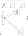
FIG. 4 is a view of an exemplary embodiment of the system ofFIG. 1 according to the inventive concepts disclosed herein. -
FIG. 5 is a view of an exemplary embodiment of an aircraft of the system ofFIG. 1 according to the inventive concepts disclosed herein. -
FIG. 6 is a view of an exemplary embodiment of the aircraft ofFIG. 5 according to the inventive concepts disclosed herein. -
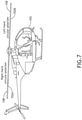
FIG. 7 is a view of an exemplary embodiment of an aircraft of the system ofFIG. 1 according to the inventive concepts disclosed herein. -
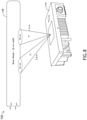
FIG. 8 is a view of an exemplary embodiment of an aircraft of the system ofFIG. 1 according to the inventive concepts disclosed herein. -
FIG. 9 is a view of an exemplary embodiment of the system ofFIG. 1 according to the inventive concepts disclosed herein. -
FIG. 10 is a diagram of an exemplary embodiment of a method according to the inventive concepts disclosed herein. - Before explaining at least one embodiment of the inventive concepts disclosed herein in detail, it is to be understood that the inventive concepts are not limited in their application to the details of construction and the arrangement of the components or steps or methodologies set forth in the following description or illustrated in the drawings. In the following detailed description of embodiments of the instant inventive concepts, numerous specific details are set forth in order to provide a more thorough understanding of the inventive concepts. However, it will be apparent to one of ordinary skill in the art having the benefit of the instant disclosure that the inventive concepts disclosed herein may be practiced without these specific details. In other instances, well-known features may not be described in detail to avoid unnecessarily complicating the instant disclosure. The inventive concepts disclosed herein are capable of other embodiments or of being practiced or carried out in various ways. Also, it is to be understood that the phraseology and terminology employed herein is for the purpose of description and should not be regarded as limiting.
- As used herein a letter following a reference numeral is intended to reference an embodiment of the feature or element that may be similar, but not necessarily identical, to a previously described element or feature bearing the same reference numeral (e.g., 1, 1a, 1b). Such shorthand notations are used for purposes of convenience only, and should not be construed to limit the inventive concepts disclosed herein in any way unless expressly stated to the contrary.
- Further, unless expressly stated to the contrary, "or" refers to an inclusive or and not to an exclusive or. For example, a condition A or B is satisfied by anyone of the following: A is true (or present) and B is false (or not present), A is false (or not present) and B is true (or present), and both A and B are true (or present).
- In addition, use of the "a" or "an" are employed to describe elements and components of embodiments of the instant inventive concepts. This is done merely for convenience and to give a general sense of the inventive concepts, and "a" and "an" are intended to include one or at least one and the singular also includes the plural unless it is obvious that it is meant otherwise.
- Finally, as used herein any reference to "one embodiment," or "some embodiments" means that a particular element, feature, structure, or characteristic described in connection with the embodiment is included in at least one embodiment of the inventive concepts disclosed herein. The appearances of the phrase "in some embodiments" in various places in the specification are not necessarily all referring to the same embodiment, and embodiments of the inventive concepts disclosed may include one or more of the features expressly described or inherently present herein, or any combination of sub-combination of two or more such features, along with any other features which may not necessarily be expressly described or inherently present in the instant disclosure.
- Broadly, embodiments of the inventive concepts disclosed herein may be directed to a method and a system (e.g., an aircraft system) including a phased array configured to at least one of transmit electromagnetic (EM) energy in a direction toward the rotor blades or receive EM energy in a direction from the rotor blades, wherein the transmitted and/or received EM energy at least one of dodges the rotor blades or reflects off the rotor blades. For example, EM energy may dodge the rotor blades for satellite communication (SATCOM) and/or high-altitude command, control, communications, computers, intelligence, surveillance, and reconnaissance (C4ISR) platforms. For example, the EM energy may reflect off the rotor blades for communication with surface communication targets and/or for ground radar operations.
- Some embodiments may reduce cost by allowing for use of a single phased array on an aircraft as compared to current aircraft that have first phased array on a top of the aircraft and a second phased array on the bottom of the aircraft. Some embodiments may increase visibility at wide scan angles. Some embodiments may provide multifunction radiofrequency (RF) capabilities for SATCOM links, air-to-ground communications, landing zone terrain radar (e.g., which may be useful for brown-out conditions), and/or target radar (e.g., mobile or stationary targets).
- Referring now to
FIGS. 1-4 , an exemplary embodiment of asystem 100 according to the inventive concepts disclosed herein is depicted. In some embodiments, the system may include at least one aircraft 102 (e.g., a helicopter or an aircraft having a propeller), at least one radar target 112 (e.g., a terrain feature, a waterfeature, a structure, and/or a surface vehicle), at least one communication target 114 (e.g., having a communication radio; e.g., a man pack radio, a vehicle radio (e.g., an automobile radio, a watercraft radio, or an aircraft radio), or a stationary radio), at least onemobile radar target 116, 118 (e.g., a vehicular radar target or a munition radar target), and/or at least onesatellite target 120, some or all of which may be communicatively coupled at any given time. - In some embodiments, the
aircraft 102 may include aspine 104, at least onerotor 106, and/or at least onephased array 110. In some embodiments, thephased array 110 may be positioned on thespine 104 of theaircraft 102. In some embodiments, thephased array 110 may be a radiofrequency (RF) phased array or an optical phased array. Therotor 106 may includerotor blades 108. - In some embodiments, as shown in
FIGS. 3-4 , theaircraft 102 may further include at least onerotor sensor 302, at least oneaircraft sensor 304, at least oneprocessor 306, memory, and/or thephased array 110, some or all of which may be communicatively coupled at any given time. In some embodiments, the at least oneprocessor 306 may be implemented as part of a single computing device or distributed among any number of computing devices configured to perform (e.g., collectively perform if more than one computing device and processor) any or all of the operations disclosed throughout. - For example, the
phased array 110 may be configured to at least one of transmit electromagnetic (EM) energy in a direction toward therotor blades 108 or receive EM energy in a direction from therotor blades 108. In some embodiments, thephased array 110 may be configured for analog beamforming (e.g., a single beam) and/or digital beamforming (e.g., one or multiple beams). In some embodiments, where thephased array 110 is an optical phased array, each of at least one of therotor blades 108 may include at least one optically reflective surface for the transmitted EM energy to reflect off. In some embodiments, where thephased array 110 is an optical phased array and/or uses micromirrors, the optical phased array may have at least one steerable laser. Such optical phased array applications may be configured for light detection and ranging (LIDAR) and/or optical over-the-air (OTA) communications. - For example, the at least one
rotor sensor 302 may be configured to provide rotor sensor data to be used to at least one of determine or obtain the rotor blade information (e.g., at least one location and/or at least one angle of therotor blades 108 at a given or an expected time). For example, the angle of arotor blade 108 can be used to determine an angle of reflection off therotor blade 108. For example, the at least onerotor sensor 302 may include a motor encoder and a blade angle sensor. The motor encoder may provide information on a position of therotor blades 108. The blade angle sensor may provide information of the blade angles. For example, a camber of therotor blades 108 may be used to direct reflected EM energy. - For example, the at least one
aircraft sensor 304 may be configured to provide aircraft data to be used to at least one of determine or obtain the aircraft information (e.g., a position and/or orientation of the aircraft at a given or expected time). - For example, the at least one
processor 306 may include at least one central processing unit (CPU), at least one graphics processing unit (GPU), at least one field-programmable gate array (FPGA), at least one application specific integrated circuit (ASIC), at least one digital signal processor, at least one virtual machine (VM) running on at least one processor, and/or the like configured to perform (e.g., collectively perform if more than one processor) and/or cause (e.g., collectively cause) to be performed any of the operations disclosed throughout. Theprocessor 306 may be configured to run various software applications or computer code stored (e.g., maintained) in a non-transitory computer-readable medium (e.g., memory) and configured to execute various instructions or operations. Theprocessor 306 may be configured to perform any or all of the operations disclosed throughout. For example, the processor 306 may be configured to: at least one of determine or obtain rotor blade information (e.g., based at least on rotor sensor data received from the rotor sensor 302), the rotor blade information including at least one location and/or at least one angle of the rotor blades 108 (e.g., at a given or an expected time); at least one of determine or obtain aircraft information (e.g., based at least on aircraft sensor data received from the aircraft sensor 304 and/or on information collected from pilot controls, for example, which may be used to calculate an angle of attack), the aircraft information including a position and an orientation of the aircraft 102; based at least on the rotor blade information and the aircraft information, determine (a) at least one time to at least one of transmit EM energy or receive EM energy and (b) at least one angle to at least one of transmit EM energy or receive EM energy; and/or based at least on the rotor blade information and the aircraft information, control the phased array 110 to adjust at least one beam pointing angle of the phased array 110 to one or more of the at least one angle and to transmit EM energy for a particular duration at the at least one adjusted beam pointing angle. - For example, based at least on such operations performed by the
processor 306, the phasedarray 110 may be configured to transmit EM energy for the particular duration at the at least one adjusted beam pointing angle, wherein the transmitted EM energy is configured to reflect off at least one of therotor blades 108 toward at least one target (e.g., 112, 114, 116, 118, and/or 120). In some embodiments, the phasedarray 110 may be a radiofrequency (RF) phased array, wherein the transmitted EM energy is further configured to reflect off the at least one target (e.g., 112, 116, and/or 118) back toward at least one of therotor blades 108, reflect off at least one of therotor blades 108, and be received by the phasedarray 110 as reflected EM energy, wherein the phasedarray 110 may be configured to measure the reflected EM energy, wherein theprocessor 306 may be further configured to calculate a range to the at least one target (e.g., 112, 116, and/or 118) based at least on the measured reflected EM energy. In some embodiments, the transmitted EM energy includes at least one communication signal, wherein the at least one target (e.g., 114, 118, and/or 120) is at least one communication target. - In some embodiments, the
processor 306 may be further configured to: determine whether to-be-transmitted or to-be-received EM energy is to dodge therotor blades 108 or to reflect off at least one of therotor blades 108. In some embodiments, theprocessor 306 may be further configured to: determine that to-be-transmitted or to-be-received EM energy is to dodge the rotor blades, wherein the to-be-transmitted or the to-be-received EM energy includes at least one communication signal to or from thesatellite 120. - In some embodiments, the
processor 306 may be further configured to: obtain or determine a timing of therotor blades 108; cause EM energy to reflect off the rotor blade in a downward facing angle; calculate geometry for use in obtaining a desired direction for EM energy receive and/or transmit functions; and/or control the phasedarray 110 to point at a specific point of arotor blade 108 to achieve a desired angle. - Referring now to
FIGS. 5-6 , an exemplary embodiment of anaircraft 102 is shown. The aircraft 102 (e.g., a vertical takeoff and landing aircraft (e.g., V-22 Osprey)) may havepositionable rotor blades 108, such as for operating in a vertical takeoff and/or landing situation (as shown inFIG. 5 ) or for operating in a forward flight situation (as shown inFIG. 6 ). Theaircraft 102 may includerotor pivot members 502 configured to adjust a position of therotors 106 androtor blades 108, such as between a forward flight rotor position (as shown inFIG. 6 ) or a vertical takeoff and landing rotor position (as shown inFIG. 5 ). - Referring now to
FIG. 7 , an exemplary embodiment of anaircraft 102 is shown. At least one of therotor blades 108 may include at least one polarizer for the transmitted EM energy to reflect off while imparting at least one polarization to the transmitted EM energy. For example, afirst rotor blade 108 of therotor blades 108 may include a right-hand polarizer 702A for the transmitted EM energy to reflect off and impart a right-hand polarization to the transmitted EM energy, and asecond rotor blade 108 of therotor blades 108 may include a left-hand polarizer 702B for the transmitted EM energy to reflect off and impart a left-hand polarization to the transmitted EM energy. In this instance, theprocessor 306 would delay transmission until thecorrect polarizer - Referring now to
FIG. 8 , a size of an EM energy beam transmitted from the phasedarray 110 may be small enough to stay on a width of therotor blade 108 at many angles. For example, a rotor blade width can be approximately 30 centimeters (cm). For example, a width of beam from a phasedarray 110 positioned on thespine 104 of theaircraft 102 can project a beam that is between 18 cm and 34 cm wide depending on a beam forming angle (e.g., approximately 7 degrees) and where on therotor blade 108 that the beam reflects off. - Referring now to
FIG. 9 , by way of example, a size of an EM energy beam transmitted from the phasedarray 110 that reflects off therotor blade 108 and onto a radar target 112 (e.g., a hazard) may fit within the beam width that is approximately 294 feet in diameter, for example, based at least on an exemplary set of factors: 7 degree beam angle, 200 vertical feet from theradar target 112 to therotor blade 108, and 1.5 meters (m) from phasedarray 110 torotor blade 108. - Referring now to
FIG. 10 , an exemplary embodiment of amethod 1000 according to the inventive concepts disclosed herein may include one or more of the following steps. Additionally, for example, some embodiments may include performing one or more instances of themethod 1000 iteratively, concurrently, and/or sequentially. Additionally, for example, at least some of the steps of themethod 1000 may be performed in parallel and/or concurrently. Additionally, in some embodiments, at least some of the steps of themethod 1000 may be performed non-sequentially. - A
step 1002 may include by a phased array, at least one of transmitting electromagnetic (EM) energy in a direction toward rotor blades or receiving EM energy in a direction from the rotor blades, wherein an aircraft includes the phase array, at least one rotor, and at least one processor communicatively coupled to the phased array, wherein the at least one rotor has the rotor blades. - A
step 1004 may include by the at least one processor, at least one of determining or obtaining rotor blade information, the rotor blade information including at least one location of the rotor blades. - A
step 1006 may include by the at least one processor, at least one of determining or obtaining aircraft information, the aircraft information including a position and an orientation of the aircraft. - A
step 1008 may include by the at least one processor, based at least on the rotor blade information and the aircraft information, determining (a) at least one time to at least one of transmit EM energy or receive EM energy and (b) at least one angle to at least one of transmit EM energy or receive EM energy. - A
step 1010 may include by the at least one processor, based at least on the rotor blade information and the aircraft information, controlling the phased array to adjust at least one beam pointing angle of the phased array to one or more of the at least one angle and to transmit EM energy for a particular duration at the at least one adjusted beam pointing angle. - A
step 1012 may include by the phased array, transmitting EM energy for the particular duration at the at least one adjusted beam pointing angle, wherein the transmitted EM energy is configured to reflect off at least one of the rotor blades toward at least one target. - Further, the
method 1000 may include any of the operations disclosed throughout. - As will be appreciated from the above, embodiments of the inventive concepts disclosed herein may be directed to a method and a system (e.g., an aircraft system) including a phased array configured to at least one of transmit electromagnetic (EM) energy in a direction toward the rotor blades or receive EM energy in a direction from the rotor blades, wherein the transmitted and/or received EM energy at least one of dodges the rotor blades or reflects off the rotor blades.
- As used throughout and as would be appreciated by those skilled in the art, "at least one non-transitory computer-readable medium" may refer to as at least one non-transitory computer-readable medium (e.g., at least one computer-readable medium implemented as hardware; e.g., at least one non-transitory processor-readable medium, at least one memory (e.g., at least one nonvolatile memory, at least one volatile memory, or a combination thereof; e.g., at least one random-access memory, at least one flash memory, at least one read-only memory (ROM) (e.g., at least one electrically erasable programmable read-only memory (EEPROM)), at least one on-processor memory (e.g., at least one on-processor cache, at least one on-processor buffer, at least one on-processor flash memory, at least one on-processor EEPROM, or a combination thereof), or a combination thereof), at least one storage device (e.g., at least one hard-disk drive, at least one tape drive, at least one solid-state drive, at least one flash drive, at least one readable and/or writable disk of at least one optical drive configured to read from and/or write to the at least one readable and/or writable disk, or a combination thereof), or a combination thereof).
- As used throughout, "at least one" means one or a plurality of; for example, "at least one" may comprise one, two, three, ..., one hundred, or more. Similarly, as used throughout, "one or more" means one or a plurality of; for example, "one or more" may comprise one, two, three, ..., one hundred, or more. Further, as used throughout, "zero or more" means zero, one, or a plurality of; for example, "zero or more" may comprise zero, one, two, three, ..., one hundred, or more.
- In the present disclosure, the methods, operations, and/or functionality disclosed may be implemented as sets of instructions or software readable by a device. Further, it is understood that the specific order or hierarchy of steps in the methods, operations, and/or functionality disclosed are examples of exemplary approaches. Based upon design preferences, it is understood that the specific order or hierarchy of steps in the methods, operations, and/or functionality can be rearranged while remaining within the scope of the inventive concepts disclosed herein. The accompanying claims may present elements of the various steps in a sample order, and are not necessarily meant to be limited to the specific order or hierarchy presented.
- It is to be understood that embodiments of the methods according to the inventive concepts disclosed herein may include one or more of the steps described herein. Further, such steps may be carried out in any desired order and two or more of the steps may be carried out simultaneously with one another. Two or more of the steps disclosed herein may be combined in a single step, and in some embodiments, one or more of the steps may be carried out as two or more sub-steps. Further, other steps or sub-steps may be carried in addition to, or as substitutes to one or more of the steps disclosed herein.
- From the above description, it is clear that the inventive concepts disclosed herein are well adapted to carry out the objects and to attain the advantages mentioned herein as well as those inherent in the inventive concepts disclosed herein. While presently preferred embodiments of the inventive concepts disclosed herein have been described for purposes of this disclosure, it will be understood that numerous changes may be made which will readily suggest themselves to those skilled in the art and which are accomplished within the broad scope and coverage of the inventive concepts disclosed and claimed herein.
Claims (15)
- A system, comprising: an aircraft (102), comprising:at least one rotor (106) having rotor blades (108);a phased array (110) configured to at least one of transmit electromagnetic (EM) energy in a direction toward the rotor blades or receive EM energy in a direction from the rotor blades; andat least one processor (306) communicatively coupled to the phased array, the at least one processor configured to:at least one of determine or obtain rotor blade information, the rotor blade information including at least one location of the rotor blades;at least one of determine or obtain aircraft information, the aircraft information including a position and an orientation of the aircraft;based at least on the rotor blade information and the aircraft information, determine (a) at least one time to at least one of transmit EM energy or receive EM energy and (b) at least one angle to at least one of transmit EM energy or receive EM energy; andbased at least on the rotor blade information and the aircraft information, control the phased array to adjust at least one beam pointing angle of the phased array to one or more of the at least one angle and to transmit EM energy for a particular duration at the at least one adjusted beam pointing angle;wherein the phased array is configured to transmit EM energy for the particular duration at the at least one adjusted beam pointing angle,wherein the transmitted EM energy is configured to reflect off at least one of the rotor blades toward at least one target.
- The system of claim 1, wherein the phased array (110) is a radiofrequency (RF) phased array, wherein the transmitted EM energy is further configured to reflect off the at least one target back toward at least one of the rotor blades, reflect off at least one of the rotor blades, and be received by the phased array as reflected EM energy, wherein the phased array is configured to measure the reflected EM energy, wherein the processor is configured to calculate a range to the at least one target based at least on the measured reflected EM energy.
- The system of claim 1 or 2, the transmitted EM energy includes at least one communication signal, wherein the at least one target is at least one communication target.
- The system of claim 1, wherein the phased array (110) is a radiofrequency (RF) phased array.
- The system of claim 1, wherein the phased array (110) is an optical phased array.
- The system of claim 5, wherein each of at least one of the rotor blades (108) includes at least one optically reflective surface for the transmitted EM energy to reflect off.
- The system of any preceding claim, wherein the at least one processor (306) is further configured to determine whether to-be-transmitted or to-be-received EM energy is to dodge the rotor blades or to reflect off at least one of the rotor blades.
- The system of claim 7, wherein the at least one processor (306) is further configured to determine that to-be-transmitted or to-be-received EM energy is to dodge the rotor blades.
- The system of claim 8, wherein the to-be-transmitted or the to-be-received EM energy includes at least one communication signal to or from a satellite.
- The system of any preceding claim, wherein the rotor blade information further includes at least one angle of the rotor blades.
- The system of any preceding claim, wherein the aircraft (102) is a helicopter, wherein the phased array is located on a spine of the helicopter.
- The system of any preceding claim, wherein the aircraft (102) further comprises at least one rotor sensor (302) configured to provide rotor sensor data to be used to at least one of determine or obtain the rotor blade information.
- The system of any preceding claim, wherein at least one of the rotor blades (108) includes at least one polarizer for the transmitted EM energy to reflect off while imparting at least one polarization to the transmitted EM energy.
- The system of any preceding claim, wherein a first rotor blade of the rotor blades includes a right-hand circular polarizer (702A) for the transmitted EM energy to reflect off and impart a right-hand circular polarization to the transmitted EM energy, wherein a second rotor blade of the rotor blades includes a left-hand circular polarizer (702B) for the transmitted EM energy to reflect off and impart a left-hand circular polarization to the transmitted EM energy.
- A method, comprising:by a phased array, at least one of transmitting electromagnetic (EM) energy in a direction toward rotor blades or receiving EM energy in a direction from the rotor blades, wherein an aircraft includes the phase array, at least one rotor, and at least one processor communicatively coupled to the phased array, wherein the at least one rotor has the rotor blades;by the at least one processor, at least one of determining or obtaining rotor blade information, the rotor blade information including at least one location of the rotor blades;by the at least one processor, at least one of determining or obtaining aircraft information, the aircraft information including a position and an orientation of the aircraft;by the at least one processor, based at least on the rotor blade information and the aircraft information, determining (a) at least one time to at least one of transmit EM energy or receive EM energy and (b) at least one angle to at least one of transmit EM energy or receive EM energy;by the at least one processor, based at least on the rotor blade information and the aircraft information, controlling the phased array to adjust at least one beam pointing angle of the phased array to one or more of the at least one angle and to transmit EM energy for a particular duration at the at least one adjusted beam pointing angle; andby the phased array, transmitting EM energy for the particular duration at the at least one adjusted beam pointing angle, wherein the transmitted EM energy is configured to reflect off at least one of the rotor blades toward at least one target.
Applications Claiming Priority (1)
| Application Number | Priority Date | Filing Date | Title |
|---|---|---|---|
| US17/027,594 US11724818B2 (en) | 2020-09-21 | 2020-09-21 | Phased array transmission reflected off rotor blade to target |
Publications (2)
| Publication Number | Publication Date |
|---|---|
| EP3972146A1 true EP3972146A1 (en) | 2022-03-23 |
| EP3972146B1 EP3972146B1 (en) | 2024-10-30 |
Family
ID=78598651
Family Applications (1)
| Application Number | Title | Priority Date | Filing Date |
|---|---|---|---|
| EP21196798.9A Active EP3972146B1 (en) | 2020-09-21 | 2021-09-15 | Phased array transmission reflected off rotor blade to target |
Country Status (2)
| Country | Link |
|---|---|
| US (1) | US11724818B2 (en) |
| EP (1) | EP3972146B1 (en) |
Families Citing this family (1)
| Publication number | Priority date | Publication date | Assignee | Title |
|---|---|---|---|---|
| KR20250155127A (en) * | 2024-04-22 | 2025-10-30 | 주식회사 케이앤에스아이앤씨 | Subminiature satellite antenna system for unmanned aerial vehicles |
Citations (2)
| Publication number | Priority date | Publication date | Assignee | Title |
|---|---|---|---|---|
| US20090051585A1 (en) * | 2007-08-20 | 2009-02-26 | Raytheon Company | Wide area high resolution SAR from a moving and hovering helicopter |
| US20170223749A1 (en) * | 2016-02-02 | 2017-08-03 | The Johns Hopkins University | Apparatus and Method for Establishing and Maintaining a Communications Link |
Family Cites Families (6)
| Publication number | Priority date | Publication date | Assignee | Title |
|---|---|---|---|---|
| US4237462A (en) | 1979-02-28 | 1980-12-02 | Lemke James U | Radar synchronizing apparatus and method |
| GB2517659B (en) | 1993-06-23 | 2015-07-22 | Dassault Electronique | Radar for helicopters |
| US6054947A (en) | 1998-08-28 | 2000-04-25 | Kosowsky; Lester H. | Helicopter rotorblade radar system |
| US8384605B2 (en) | 2009-02-25 | 2013-02-26 | Sikorsky Aircraft Corporation | Wireless communication between a rotating frame of reference and a non-rotating frame of reference |
| US20140349637A1 (en) * | 2013-03-15 | 2014-11-27 | Elwha LLC, a limited liability corporation of the State of Delaware | Facilitating wireless communication in conjunction with orientation position |
| US10439293B2 (en) | 2017-03-20 | 2019-10-08 | Lockheed Martin Corporation | Antenna systems using aircraft propellers |
-
2020
- 2020-09-21 US US17/027,594 patent/US11724818B2/en active Active
-
2021
- 2021-09-15 EP EP21196798.9A patent/EP3972146B1/en active Active
Patent Citations (2)
| Publication number | Priority date | Publication date | Assignee | Title |
|---|---|---|---|---|
| US20090051585A1 (en) * | 2007-08-20 | 2009-02-26 | Raytheon Company | Wide area high resolution SAR from a moving and hovering helicopter |
| US20170223749A1 (en) * | 2016-02-02 | 2017-08-03 | The Johns Hopkins University | Apparatus and Method for Establishing and Maintaining a Communications Link |
Also Published As
| Publication number | Publication date |
|---|---|
| US20220089292A1 (en) | 2022-03-24 |
| EP3972146B1 (en) | 2024-10-30 |
| US11724818B2 (en) | 2023-08-15 |
Similar Documents
| Publication | Publication Date | Title |
|---|---|---|
| CN108398677B (en) | Three-coordinate continuous wave one-dimensional phase scanning unmanned aerial vehicle low-altitude target detection system | |
| EP0864105B1 (en) | Method and apparatus for accomplishing extended range tcas | |
| JP2021042957A (en) | System and method for reflecting radar beam using aircraft | |
| EP2194400B1 (en) | A surveillance system comprising a radar antenna mounted on a blade of a windmill | |
| US11342684B2 (en) | Dual edge-fed slotted waveguide antenna for millimeter wave applications | |
| EP2172788A1 (en) | Radar system for obstacle avoidance | |
| EP3447530A1 (en) | Determining a location of a runway based on radar signals | |
| US10564256B2 (en) | Beam sharpening radar system and method | |
| CN109313452A (en) | UAV obstacle avoidance control method, radar system and UAV | |
| CN107783133B (en) | Fixed-wing UAV anti-collision system and anti-collision method of millimeter wave radar | |
| US20130265185A1 (en) | Proximity warning system for helicopters | |
| WO1997020230A9 (en) | Method and apparatus for accomplishing extended range tcas | |
| GB2463987A (en) | Obstacle avoidance radar for UAVs | |
| EP3855211B1 (en) | Multistatic radar utilizing 5g signals | |
| US11558106B2 (en) | Signal interference mitigation for UAVs | |
| EP3972146B1 (en) | Phased array transmission reflected off rotor blade to target | |
| US11320532B2 (en) | Coordinated detecting of objects in an airspace | |
| KR102624771B1 (en) | Unmanned aerial vehicle jamming apparatus and method | |
| EP4279945A1 (en) | Reprogrammable radar system and method | |
| US20090251358A1 (en) | Radar altimeter with forward looking radar and data transfer capabilities | |
| CN111290434B (en) | Unmanned aerial vehicle guiding method, system, equipment and storage medium | |
| US10747217B1 (en) | Distributed directional antenna | |
| EP3378761B1 (en) | Antenna systems using aircraft propellers | |
| US20250389814A1 (en) | Control Method and Device, and Aerial Vehicle | |
| US20250165011A1 (en) | Drone system for synthetic aperture radar operation and operating method thereof |
Legal Events
| Date | Code | Title | Description |
|---|---|---|---|
| PUAI | Public reference made under article 153(3) epc to a published international application that has entered the european phase |
Free format text: ORIGINAL CODE: 0009012 |
|
| STAA | Information on the status of an ep patent application or granted ep patent |
Free format text: STATUS: THE APPLICATION HAS BEEN PUBLISHED |
|
| AK | Designated contracting states |
Kind code of ref document: A1 Designated state(s): AL AT BE BG CH CY CZ DE DK EE ES FI FR GB GR HR HU IE IS IT LI LT LU LV MC MK MT NL NO PL PT RO RS SE SI SK SM TR |
|
| STAA | Information on the status of an ep patent application or granted ep patent |
Free format text: STATUS: REQUEST FOR EXAMINATION WAS MADE |
|
| 17P | Request for examination filed |
Effective date: 20220919 |
|
| RBV | Designated contracting states (corrected) |
Designated state(s): AL AT BE BG CH CY CZ DE DK EE ES FI FR GB GR HR HU IE IS IT LI LT LU LV MC MK MT NL NO PL PT RO RS SE SI SK SM TR |
|
| GRAP | Despatch of communication of intention to grant a patent |
Free format text: ORIGINAL CODE: EPIDOSNIGR1 |
|
| STAA | Information on the status of an ep patent application or granted ep patent |
Free format text: STATUS: GRANT OF PATENT IS INTENDED |
|
| RIC1 | Information provided on ipc code assigned before grant |
Ipc: G01S 17/933 20200101ALI20240405BHEP Ipc: H01Q 15/24 20060101ALI20240405BHEP Ipc: G01S 13/935 20200101ALI20240405BHEP Ipc: G01S 13/933 20200101ALI20240405BHEP Ipc: G01S 13/02 20060101ALI20240405BHEP Ipc: B64D 47/02 20060101ALI20240405BHEP Ipc: B64C 27/04 20060101ALI20240405BHEP Ipc: B64C 1/36 20060101ALI20240405BHEP Ipc: H01Q 1/28 20060101ALI20240405BHEP Ipc: G01S 13/88 20060101ALI20240405BHEP Ipc: B64C 27/06 20060101ALI20240405BHEP Ipc: H04B 7/10 20170101ALI20240405BHEP Ipc: H04W 16/28 20090101ALI20240405BHEP Ipc: H04B 7/06 20060101AFI20240405BHEP |
|
| INTG | Intention to grant announced |
Effective date: 20240513 |
|
| GRAS | Grant fee paid |
Free format text: ORIGINAL CODE: EPIDOSNIGR3 |
|
| GRAA | (expected) grant |
Free format text: ORIGINAL CODE: 0009210 |
|
| STAA | Information on the status of an ep patent application or granted ep patent |
Free format text: STATUS: THE PATENT HAS BEEN GRANTED |
|
| AK | Designated contracting states |
Kind code of ref document: B1 Designated state(s): AL AT BE BG CH CY CZ DE DK EE ES FI FR GB GR HR HU IE IS IT LI LT LU LV MC MK MT NL NO PL PT RO RS SE SI SK SM TR |
|
| REG | Reference to a national code |
Ref country code: GB Ref legal event code: FG4D |
|
| REG | Reference to a national code |
Ref country code: CH Ref legal event code: EP |
|
| REG | Reference to a national code |
Ref country code: IE Ref legal event code: FG4D |
|
| REG | Reference to a national code |
Ref country code: DE Ref legal event code: R096 Ref document number: 602021020928 Country of ref document: DE |
|
| REG | Reference to a national code |
Ref country code: LT Ref legal event code: MG9D |
|
| REG | Reference to a national code |
Ref country code: NL Ref legal event code: MP Effective date: 20241030 |
|
| PG25 | Lapsed in a contracting state [announced via postgrant information from national office to epo] |
Ref country code: PT Free format text: LAPSE BECAUSE OF FAILURE TO SUBMIT A TRANSLATION OF THE DESCRIPTION OR TO PAY THE FEE WITHIN THE PRESCRIBED TIME-LIMIT Effective date: 20250228 Ref country code: IS Free format text: LAPSE BECAUSE OF FAILURE TO SUBMIT A TRANSLATION OF THE DESCRIPTION OR TO PAY THE FEE WITHIN THE PRESCRIBED TIME-LIMIT Effective date: 20250228 Ref country code: HR Free format text: LAPSE BECAUSE OF FAILURE TO SUBMIT A TRANSLATION OF THE DESCRIPTION OR TO PAY THE FEE WITHIN THE PRESCRIBED TIME-LIMIT Effective date: 20241030 |
|
| PG25 | Lapsed in a contracting state [announced via postgrant information from national office to epo] |
Ref country code: NL Free format text: LAPSE BECAUSE OF FAILURE TO SUBMIT A TRANSLATION OF THE DESCRIPTION OR TO PAY THE FEE WITHIN THE PRESCRIBED TIME-LIMIT Effective date: 20241030 Ref country code: FI Free format text: LAPSE BECAUSE OF FAILURE TO SUBMIT A TRANSLATION OF THE DESCRIPTION OR TO PAY THE FEE WITHIN THE PRESCRIBED TIME-LIMIT Effective date: 20241030 |
|
| REG | Reference to a national code |
Ref country code: AT Ref legal event code: MK05 Ref document number: 1737937 Country of ref document: AT Kind code of ref document: T Effective date: 20241030 |
|
| PG25 | Lapsed in a contracting state [announced via postgrant information from national office to epo] |
Ref country code: BG Free format text: LAPSE BECAUSE OF FAILURE TO SUBMIT A TRANSLATION OF THE DESCRIPTION OR TO PAY THE FEE WITHIN THE PRESCRIBED TIME-LIMIT Effective date: 20241030 |
|
| PG25 | Lapsed in a contracting state [announced via postgrant information from national office to epo] |
Ref country code: ES Free format text: LAPSE BECAUSE OF FAILURE TO SUBMIT A TRANSLATION OF THE DESCRIPTION OR TO PAY THE FEE WITHIN THE PRESCRIBED TIME-LIMIT Effective date: 20241030 |
|
| PG25 | Lapsed in a contracting state [announced via postgrant information from national office to epo] |
Ref country code: NO Free format text: LAPSE BECAUSE OF FAILURE TO SUBMIT A TRANSLATION OF THE DESCRIPTION OR TO PAY THE FEE WITHIN THE PRESCRIBED TIME-LIMIT Effective date: 20250130 |
|
| PG25 | Lapsed in a contracting state [announced via postgrant information from national office to epo] |
Ref country code: GR Free format text: LAPSE BECAUSE OF FAILURE TO SUBMIT A TRANSLATION OF THE DESCRIPTION OR TO PAY THE FEE WITHIN THE PRESCRIBED TIME-LIMIT Effective date: 20250131 Ref country code: LV Free format text: LAPSE BECAUSE OF FAILURE TO SUBMIT A TRANSLATION OF THE DESCRIPTION OR TO PAY THE FEE WITHIN THE PRESCRIBED TIME-LIMIT Effective date: 20241030 Ref country code: AT Free format text: LAPSE BECAUSE OF FAILURE TO SUBMIT A TRANSLATION OF THE DESCRIPTION OR TO PAY THE FEE WITHIN THE PRESCRIBED TIME-LIMIT Effective date: 20241030 |
|
| PG25 | Lapsed in a contracting state [announced via postgrant information from national office to epo] |
Ref country code: PL Free format text: LAPSE BECAUSE OF FAILURE TO SUBMIT A TRANSLATION OF THE DESCRIPTION OR TO PAY THE FEE WITHIN THE PRESCRIBED TIME-LIMIT Effective date: 20241030 |
|
| PG25 | Lapsed in a contracting state [announced via postgrant information from national office to epo] |
Ref country code: RS Free format text: LAPSE BECAUSE OF FAILURE TO SUBMIT A TRANSLATION OF THE DESCRIPTION OR TO PAY THE FEE WITHIN THE PRESCRIBED TIME-LIMIT Effective date: 20250130 |
|
| PG25 | Lapsed in a contracting state [announced via postgrant information from national office to epo] |
Ref country code: SM Free format text: LAPSE BECAUSE OF FAILURE TO SUBMIT A TRANSLATION OF THE DESCRIPTION OR TO PAY THE FEE WITHIN THE PRESCRIBED TIME-LIMIT Effective date: 20241030 |
|
| PG25 | Lapsed in a contracting state [announced via postgrant information from national office to epo] |
Ref country code: DK Free format text: LAPSE BECAUSE OF FAILURE TO SUBMIT A TRANSLATION OF THE DESCRIPTION OR TO PAY THE FEE WITHIN THE PRESCRIBED TIME-LIMIT Effective date: 20241030 |
|
| PG25 | Lapsed in a contracting state [announced via postgrant information from national office to epo] |
Ref country code: EE Free format text: LAPSE BECAUSE OF FAILURE TO SUBMIT A TRANSLATION OF THE DESCRIPTION OR TO PAY THE FEE WITHIN THE PRESCRIBED TIME-LIMIT Effective date: 20241030 |
|
| PG25 | Lapsed in a contracting state [announced via postgrant information from national office to epo] |
Ref country code: RO Free format text: LAPSE BECAUSE OF FAILURE TO SUBMIT A TRANSLATION OF THE DESCRIPTION OR TO PAY THE FEE WITHIN THE PRESCRIBED TIME-LIMIT Effective date: 20241030 |
|
| PG25 | Lapsed in a contracting state [announced via postgrant information from national office to epo] |
Ref country code: SK Free format text: LAPSE BECAUSE OF FAILURE TO SUBMIT A TRANSLATION OF THE DESCRIPTION OR TO PAY THE FEE WITHIN THE PRESCRIBED TIME-LIMIT Effective date: 20241030 |
|
| PG25 | Lapsed in a contracting state [announced via postgrant information from national office to epo] |
Ref country code: CZ Free format text: LAPSE BECAUSE OF FAILURE TO SUBMIT A TRANSLATION OF THE DESCRIPTION OR TO PAY THE FEE WITHIN THE PRESCRIBED TIME-LIMIT Effective date: 20241030 |
|
| PG25 | Lapsed in a contracting state [announced via postgrant information from national office to epo] |
Ref country code: IT Free format text: LAPSE BECAUSE OF FAILURE TO SUBMIT A TRANSLATION OF THE DESCRIPTION OR TO PAY THE FEE WITHIN THE PRESCRIBED TIME-LIMIT Effective date: 20241030 |
|
| REG | Reference to a national code |
Ref country code: DE Ref legal event code: R097 Ref document number: 602021020928 Country of ref document: DE |
|
| PLBE | No opposition filed within time limit |
Free format text: ORIGINAL CODE: 0009261 |
|
| STAA | Information on the status of an ep patent application or granted ep patent |
Free format text: STATUS: NO OPPOSITION FILED WITHIN TIME LIMIT |
|
| PG25 | Lapsed in a contracting state [announced via postgrant information from national office to epo] |
Ref country code: SE Free format text: LAPSE BECAUSE OF FAILURE TO SUBMIT A TRANSLATION OF THE DESCRIPTION OR TO PAY THE FEE WITHIN THE PRESCRIBED TIME-LIMIT Effective date: 20241030 |
|
| 26N | No opposition filed |
Effective date: 20250731 |
|
| PGFP | Annual fee paid to national office [announced via postgrant information from national office to epo] |
Ref country code: DE Payment date: 20250820 Year of fee payment: 5 |
|
| PGFP | Annual fee paid to national office [announced via postgrant information from national office to epo] |
Ref country code: GB Payment date: 20250820 Year of fee payment: 5 |
|
| PGFP | Annual fee paid to national office [announced via postgrant information from national office to epo] |
Ref country code: FR Payment date: 20250820 Year of fee payment: 5 |
|
| REG | Reference to a national code |
Ref country code: CH Ref legal event code: H13 Free format text: ST27 STATUS EVENT CODE: U-0-0-H10-H13 (AS PROVIDED BY THE NATIONAL OFFICE) Effective date: 20260504 |