EP3972103A1 - Fault current limiting method in combination with bridge-arm current suppression for vsc-hvdc - Google Patents
Fault current limiting method in combination with bridge-arm current suppression for vsc-hvdc Download PDFInfo
- Publication number
- EP3972103A1 EP3972103A1 EP21170561.1A EP21170561A EP3972103A1 EP 3972103 A1 EP3972103 A1 EP 3972103A1 EP 21170561 A EP21170561 A EP 21170561A EP 3972103 A1 EP3972103 A1 EP 3972103A1
- Authority
- EP
- European Patent Office
- Prior art keywords
- current
- fault
- bridge
- converter
- arm
- Prior art date
- Legal status (The legal status is an assumption and is not a legal conclusion. Google has not performed a legal analysis and makes no representation as to the accuracy of the status listed.)
- Granted
Links
Images


Classifications
-
- H—ELECTRICITY
- H02—GENERATION; CONVERSION OR DISTRIBUTION OF ELECTRIC POWER
- H02M—APPARATUS FOR CONVERSION BETWEEN AC AND AC, BETWEEN AC AND DC, OR BETWEEN DC AND DC, AND FOR USE WITH MAINS OR SIMILAR POWER SUPPLY SYSTEMS; CONVERSION OF DC OR AC INPUT POWER INTO SURGE OUTPUT POWER; CONTROL OR REGULATION THEREOF
- H02M1/00—Details of apparatus for conversion
- H02M1/32—Means for protecting converters other than automatic disconnection
-
- H—ELECTRICITY
- H02—GENERATION; CONVERSION OR DISTRIBUTION OF ELECTRIC POWER
- H02H—EMERGENCY PROTECTIVE CIRCUIT ARRANGEMENTS
- H02H7/00—Emergency protective circuit arrangements specially adapted for specific types of electric machines or apparatus or for sectionalised protection of cable or line systems, and effecting automatic switching in the event of an undesired change from normal working conditions
- H02H7/26—Sectionalised protection of cable or line systems, e.g. for disconnecting a section on which a short-circuit, earth fault, or arc discharge has occured
- H02H7/268—Sectionalised protection of cable or line systems, e.g. for disconnecting a section on which a short-circuit, earth fault, or arc discharge has occured for DC systems
-
- H—ELECTRICITY
- H02—GENERATION; CONVERSION OR DISTRIBUTION OF ELECTRIC POWER
- H02J—ELECTRIC POWER NETWORKS; CIRCUIT ARRANGEMENTS OR SYSTEMS FOR SUPPLYING OR DISTRIBUTING ELECTRIC POWER; SYSTEMS FOR STORING ELECTRIC ENERGY
- H02J3/00—Circuit arrangements for AC mains or AC distribution networks
- H02J3/36—Arrangements for transfer of electric power between AC networks via high-voltage DC [HVDC] links; Arrangements for transfer of electric power between generators and networks via HVDC links
-
- H—ELECTRICITY
- H02—GENERATION; CONVERSION OR DISTRIBUTION OF ELECTRIC POWER
- H02M—APPARATUS FOR CONVERSION BETWEEN AC AND AC, BETWEEN AC AND DC, OR BETWEEN DC AND DC, AND FOR USE WITH MAINS OR SIMILAR POWER SUPPLY SYSTEMS; CONVERSION OF DC OR AC INPUT POWER INTO SURGE OUTPUT POWER; CONTROL OR REGULATION THEREOF
- H02M7/00—Conversion of AC power input into DC power output; Conversion of DC power input into AC power output
- H02M7/42—Conversion of DC power input into AC power output without possibility of reversal
- H02M7/44—Conversion of DC power input into AC power output without possibility of reversal by static converters
- H02M7/48—Conversion of DC power input into AC power output without possibility of reversal by static converters using discharge tubes with control electrode or semiconductor devices with control electrode
- H02M7/483—Converters with outputs that each can have more than two voltages levels
- H02M7/4835—Converters with outputs that each can have more than two voltages levels comprising two or more cells, each including a switchable capacitor, the capacitors having a nominal charge voltage which corresponds to a given fraction of the input voltage, and the capacitors being selectively connected in series to determine the instantaneous output voltage
-
- Y—GENERAL TAGGING OF NEW TECHNOLOGICAL DEVELOPMENTS; GENERAL TAGGING OF CROSS-SECTIONAL TECHNOLOGIES SPANNING OVER SEVERAL SECTIONS OF THE IPC; TECHNICAL SUBJECTS COVERED BY FORMER USPC CROSS-REFERENCE ART COLLECTIONS [XRACs] AND DIGESTS
- Y02—TECHNOLOGIES OR APPLICATIONS FOR MITIGATION OR ADAPTATION AGAINST CLIMATE CHANGE
- Y02E—REDUCTION OF GREENHOUSE GAS [GHG] EMISSIONS, RELATED TO ENERGY GENERATION, TRANSMISSION OR DISTRIBUTION
- Y02E60/00—Enabling technologies; Technologies with a potential or indirect contribution to GHG emissions mitigation
- Y02E60/60—Arrangements for transfer of electric power between AC networks or generators via a high voltage DC link [HVCD]
Definitions
- the present invention relates to the field of control of voltage source converter-based high-voltage direct current transmission (VSC-HVDC) technology, and more particularly, to a fault current limiting method in combination with bridge-arm current suppression for VSC-HVDC.
- VSC-HVDC voltage source converter-based high-voltage direct current transmission
- VSC-HVDC is an effective technical approach for the asynchronous interconnection of modern power systems and the integration of renewable energy.
- the modular multilevel converter (MMC) is widely recognized as an inevitable choice for constructing direct current (DC) power grids due to its high-voltage and large-capacity transmission capacity.
- DC direct current
- thyristors the fully-controlled electronic devices in MMC are prone to damage due to overcurrent in the event of DC fault, which hinders the development of DC power grids.
- a common method is to endow the MMC with the ability to clear the fault current by changing the topology of sub-modules such as full-bridge sub-modules and clamp double sub-modules, synthesize the DC voltage to zero by locking the insulated gate bipolar transistors (IGBT) in the sub-module, and block the alternating current (AC) feed current to clear the fault current.
- IGBT insulated gate bipolar transistors
- AC alternating current
- prior projects typically employ half-bridge MMCs.
- the DC circuit breaker (DCCB) is used as a conventional means to isolate the DC fault.
- the matching DC circuit breaker technology is not yet evolved. It is, therefore, highly desirable to conduct research on the DC fault current suppression measures.
- Prior methods for fault current suppression mainly include: combined fault current limiting equipment ( Eryong GUAN, Xinzhou DONG, Hao WANG, Study on Combined Fault Current Limiting Equipment and Operation Strategy for DC Grid, Proceedings of the Chinese Society for Electrical Engineering ), in which the combined fault current limiting equipment is a combination of DC current limiter and flexible DC converter with the ability of fault current clearance; a novel hybrid DC fault current limiter topology ( Naizheng HAN, Xiufang JIA, Xibei ZHAO, Jianzhong XU, Chengyong ZHAO, Novel Hybrid DC Fault Current Limiter Topology, Proceedings of the Chinese Society for Electrical Engineering ), in which the main current limiting circuit employs thyristor devices to quickly bypass the current limiting inductor when the DC circuit breaker breaks the circuit; the above two measures require additional installation of fault current suppression devices, which increases the engineering investment costs; a modular multilevel converter with DC fault current limiting capability ( Ruixiang HAO, Xiaofeng
- the technical problem to be solved by the present invention is to provide a fault current limiting method in combination with bridge-arm current suppression for VSC-HVDC, aimed at realizing the purpose of limiting the DC fault current, and reducing the requirement for the breaking capacity of the DC circuit breaker, while also preventing the converter from being blocked before the action of the DC circuit breaker to ensure that the transmission of the active power will not be interrupted during the fault.
- the present invention adopts the following technical solution.
- a fault current limiting method in combination with a bridge-arm current suppression for VSC-HVDC includes the following steps:
- step 6 the deionization time is 200 ms-300 ms.
- the present invention has the following advantages.
- the DC impedance is reshaped by adaptively changing the switching coefficient of the converter, so as to realize the purpose of limiting the DC fault current while reducing the requirement for the breaking capacity of the DC circuit breaker.
- the bridge-arm current suppression control is added to the current inner loop to reduce the bridge-arm current to prevent the converter from being blocked before the action of the DC circuit breaker.
- the present invention does not need to invest extra equipment, and adds a bridge-arm current suppression mode to ensure that the transmission of the active power will not be interrupted during the fault, thereby improving the reliability of operation of the DC system.
- the present invention provides a fault current limiting method in combination with the bridge-arm current suppression for VSC-HVDC, which includes:
- Verification scheme 1 DC fault current suppression control
- control parameters are set as shown in Table 1: Table 1 Control parameters of Verification scheme 1 f z T a T b 72 Hz 0.0022 s 0.0595 s 41 Hz 0.0039 s 0.0339 s 22.5 Hz 0.0071 s 0.0186 s
- the value of the fault current at 6 ms can be reduced by 40%, 49.4% and 57%, respectively.
- the simulation verification is shown in FIG. 4 .
- the control method of the present invention achieves a remarkable effect in fault current suppression.
- Verification scheme 2 bridge-arm current suppression control
- FIGS. 5-7 respectively show the waveforms of the bridge-arm current after the bridge-arm current suppression control is added under the three groups of different parameters in Table 1.
- the effect of extending the blocking time of the converter station is shown in Table 2.
- Table 2 Bridge-arm current suppression effect under different control parameters f z blocking time of converter station Percentage of extending of the blocking time Without bridge-arm current suppression control With bridge-arm current suppression control 72 Hz 2.30 ms 7.60 ms 230% 41 Hz 2.40 ms 8.65 ms 260% 22.5 Hz 2.50 ms 9.80 ms 292%
- control method of the present invention can effectively reduce the bridge-arm current and ensure that the converter is not blocked before the DC circuit breaker breaks.
Landscapes
- Engineering & Computer Science (AREA)
- Power Engineering (AREA)
- Rectifiers (AREA)
- Inverter Devices (AREA)
Abstract
Description
- The present invention relates to the field of control of voltage source converter-based high-voltage direct current transmission (VSC-HVDC) technology, and more particularly, to a fault current limiting method in combination with bridge-arm current suppression for VSC-HVDC.
- VSC-HVDC is an effective technical approach for the asynchronous interconnection of modern power systems and the integration of renewable energy. In particular, the modular multilevel converter (MMC) is widely recognized as an inevitable choice for constructing direct current (DC) power grids due to its high-voltage and large-capacity transmission capacity. Compared with thyristors, however, the fully-controlled electronic devices in MMC are prone to damage due to overcurrent in the event of DC fault, which hinders the development of DC power grids.
- To suppress the fault current, a common method is to endow the MMC with the ability to clear the fault current by changing the topology of sub-modules such as full-bridge sub-modules and clamp double sub-modules, synthesize the DC voltage to zero by locking the insulated gate bipolar transistors (IGBT) in the sub-module, and block the alternating current (AC) feed current to clear the fault current. However, to minimize the investment cost, prior projects typically employ half-bridge MMCs. For such DC systems, the DC circuit breaker (DCCB) is used as a conventional means to isolate the DC fault. However, with the improvement of the voltage level and transmission capacity of the DC system, the matching DC circuit breaker technology is not yet evolved. It is, therefore, highly desirable to conduct research on the DC fault current suppression measures.
- Prior methods for fault current suppression mainly include: combined fault current limiting equipment (Eryong GUAN, Xinzhou DONG, Hao WANG, Study on Combined Fault Current Limiting Equipment and Operation Strategy for DC Grid, Proceedings of the Chinese Society for Electrical Engineering), in which the combined fault current limiting equipment is a combination of DC current limiter and flexible DC converter with the ability of fault current clearance; a novel hybrid DC fault current limiter topology (Naizheng HAN, Xiufang JIA, Xibei ZHAO, Jianzhong XU, Chengyong ZHAO, Novel Hybrid DC Fault Current Limiter Topology, Proceedings of the Chinese Society for Electrical Engineering), in which the main current limiting circuit employs thyristor devices to quickly bypass the current limiting inductor when the DC circuit breaker breaks the circuit; the above two measures require additional installation of fault current suppression devices, which increases the engineering investment costs; a modular multilevel converter with DC fault current limiting capability (Ruixiang HAO, Xiaofeng YANG, Yao XUE, Bowei CHEN, Zhiqin LIN, Hu SUN, Modular Multilevel Converter with DC Fault Current Limiting Capability, Transactions of China Electrotechnical Society), in which the fault current is limited by an extra blocking IGBT device together with its bypass snubber circuit arranged in the AC output port; in this suppression mode, the improved sub-module topology adds the IGBT device and its bypass snubber circuit, increases the equipment investment costs, and thus cannot be satisfactorily applied to the existing projects; a fault current limiting control strategy based on virtual reactor (Li X, Li Z, Zhao B, et al. HVDC Reactor Reduction Method Based on Virtual Reactor Fault Current Limiting Control of MMC. IEEE Transactions on Industrial Electronics, 2019), in which the inductance of the virtual reactor can be directly controlled by the discharge degree of sub-module capacitors to realize the purpose of limiting the fault current; an adaptive fault current limiting control strategy (Ni B, Xiang W, Zhou M, et al. An Adaptive Fault Current Limiting Control for MMC and Its Application in DC Grid. IEEE Transactions on Power Delivery, 2020), in which the current can be limited by adaptively altering the inserted number of sub-modules; the last two methods only consider the suppression of the DC fault current, but do not consider the suppression of the bridge-arm current, and thus cannot guarantee that the power transmission of the converter station will not be interrupted during the fault.
- The technical problem to be solved by the present invention is to provide a fault current limiting method in combination with bridge-arm current suppression for VSC-HVDC, aimed at realizing the purpose of limiting the DC fault current, and reducing the requirement for the breaking capacity of the DC circuit breaker, while also preventing the converter from being blocked before the action of the DC circuit breaker to ensure that the transmission of the active power will not be interrupted during the fault.
- In order to solve the above-mentioned technical problems, the present invention adopts the following technical solution.
- A fault current limiting method in combination with a bridge-arm current suppression for VSC-HVDC includes the following steps:
- step 1: extracting an equivalent resistance R eq, an equivalent inductance L eq and an equivalent capacitance C eq of a converter, an inductance value L d of a DC smoothing reactor, a rated DC voltage U dcN, a proportional parameter k p and an integral parameter k i of a current inner loop proportional-integral (PI) controller, a DC current real-time value i dc, and a DC current reference value i dcref;
- step 2: setting a corner frequency f z of DC current suppression control according to a fault current suppression requirement, and calculating a switching coefficient


- step 3: in an inner loop current control stage, adding the bridge-arm current suppression control to a reference current input point of a d axis, wherein a time constant of the bridge-arm current suppression control is

- step 4: unlocking a converter station to enable a VSC-HVDC system to operate stably;
- step 5: setting a DC pole-to-pole fault to occur; when a rising rate of the DC current is detected to exceed U dcN/2L dc, triggering the DC suppression control, and changing the initial switching coefficient of the converter to the calculated adaptive switching coefficient K c; meanwhile, adding the bridge-arm current suppression control to reduce a bridge-arm current by suppressing an AC current component; after a delay, breaking a fault current by a DC circuit breaker and isolating the fault; and after the fault is isolated, exiting operation of the two controls; and
- step 6: after a deionization time, reclosing the DC circuit breaker to enable the system to resume operation.
- Further, in step 6, the deionization time is 200 ms-300 ms.
- Compared with the prior art, the present invention has the following advantages. The DC impedance is reshaped by adaptively changing the switching coefficient of the converter, so as to realize the purpose of limiting the DC fault current while reducing the requirement for the breaking capacity of the DC circuit breaker. In addition, the bridge-arm current suppression control is added to the current inner loop to reduce the bridge-arm current to prevent the converter from being blocked before the action of the DC circuit breaker. Compared with the prior methods, the present invention does not need to invest extra equipment, and adds a bridge-arm current suppression mode to ensure that the transmission of the active power will not be interrupted during the fault, thereby improving the reliability of operation of the DC system.
-
-
FIG. 1 is a schematic diagram of a method with the bridge-arm current suppression. -
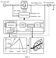
FIG. 2 is a schematic diagram of the cooperation between the combined suppression control of the fault current and the DC circuit breaker. -
FIG. 3 is a schematic diagram of VSC-HVDC systems at both ends. -
FIG. 4 is a graph showing simulation verification of a fault current without control and with the fault current suppression. -
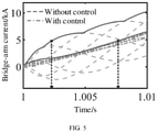
FIG. 5 is a waveform diagram of bridge-arm currents after adding the bridge-arm current suppression control under different parameters, wherein f z=72Hz. -
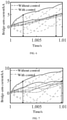
FIG. 6 is a waveform diagram of bridge-arm currents after adding the bridge-arm current suppression control under different parameters, wherein f z=41Hz. -
FIG. 7 is a waveform diagram of bridge-arm currents after adding the bridge-arm current suppression control under different parameters, wherein f z=22.5Hz. - The present invention is further explained in detail below with reference to the drawings and specific embodiments. The present invention provides a fault current limiting method in combination with the bridge-arm current suppression for VSC-HVDC, which includes:
- 1. The equivalent resistance R eq, the equivalent inductance L eq and the equivalent capacitance C eq of the converter, the inductance value L d of the DC smoothing reactor, the rated DC voltage U dcN, the proportional parameter k p and the integral parameter k i of the current inner loop proportional-integral (PI) controller, the DC current real-time value i dc, and the DC current reference value i dcref are extracted.
- 2. The corner frequency f z of the DC current suppression control is set according to the fault current suppression requirement, and the switching coefficient


- 3. In the inner loop current control stage, the bridge-arm current suppression control is added to the reference current input point of the d axis, wherein the time constant of the bridge-arm current suppression control is

- 4. The converter station is unlocked to enable the VSC-HVDC system to operate stably.
- 5. The DC pole-to-pole fault is set to occur. When it is detected that the rising rate of the DC current exceeds U dcN/2L dc, the DC suppression control is triggered, and the initial switching coefficient of the converter is changed to the calculated adaptive switching coefficient K c, to achieve the effect of bypassing parts of sub-modules to reduce the DC fault current. Meanwhile, the bridge-arm current suppression control is added to reduce the bridge-arm current by suppressing the AC current component. After a delay of 6 ms, the DC circuit breaker breaks the fault current, and isolates the fault. After the fault is isolated, the two controls exit operation.
- 6. After a deionization time of 200 ms-300 ms, the DC circuit breaker is reclosed to enable the system to resume operation.
- Taking the VSC-HVDC systems at both ends in
FIG. 3 as an example to verify the effectiveness of the method of the present invention as follows. - The control parameters are set as shown in Table 1:
Table 1 Control parameters of Verification scheme 1 fz Ta T b 72 Hz 0.0022 s 0.0595 s 41 Hz 0.0039 s 0.0339 s 22.5 Hz 0.0071 s 0.0186 s - Under the three groups of different parameters in Table 1, the value of the fault current at 6 ms can be reduced by 40%, 49.4% and 57%, respectively. The simulation verification is shown in
FIG. 4 . Compared with the fault current without the control, the control method of the present invention achieves a remarkable effect in fault current suppression. -
FIGS. 5-7 respectively show the waveforms of the bridge-arm current after the bridge-arm current suppression control is added under the three groups of different parameters in Table 1. The effect of extending the blocking time of the converter station is shown in Table 2.Table 2 Bridge-arm current suppression effect under different control parameters f z blocking time of converter station Percentage of extending of the blocking time Without bridge-arm current suppression control With bridge-arm current suppression control 72 Hz 2.30 ms 7.60 ms 230% 41 Hz 2.40 ms 8.65 ms 260% 22.5 Hz 2.50 ms 9.80 ms 292% - It can be seen that the control method of the present invention can effectively reduce the bridge-arm current and ensure that the converter is not blocked before the DC circuit breaker breaks.
Claims (2)
- A fault current limiting method in combination with a bridge-arm current suppression for VSC-HVDC, comprising the following steps:step 1: extracting an equivalent resistance R eq, an equivalent inductance L eq and an equivalent capacitance C eq of a converter, an inductance value L d of a DC smoothing reactor, a rated DC voltage U dcN, a proportional parameter k p and an integral parameter k i of a current inner loop proportional-integral (PI) controller, a DC current real-time value i dc, and a DC current reference value i dcref;step 2: setting a corner frequency f z of a DC current suppression control according to a fault current suppression requirement, and calculating a switching coefficient

 step 3: in an inner loop current control stage, adding a bridge-arm current suppression control to a reference current input point of a d axis, wherein a time constant of the bridge-arm current suppression control is
 step 4: unlocking a converter station to enable a VSC-HVDC system to operate stably;step 5: setting a DC pole-to-pole fault to occur; when a rising rate of a DC current is detected to exceed U dcN/2L dc, triggering the DC suppression control, and changing the initial switching coefficient of the converter to a calculated adaptive switching coefficient K c; meanwhile, adding the bridge-arm current suppression control to reduce a bridge-arm current by suppressing an AC current component; after a delay, breaking a fault current by a DC circuit breaker and isolating the fault; and after the fault is isolated, exiting operation of the two controls; andstep 6: after a deionization time, reclosing the DC circuit breaker to enable the system to resume operation.
 - The fault current limiting method in combination with the bridge-arm current suppression for the VSC-HVDC according to claim 1, characterized in that, in step 6, the deionization time is 200 ms-300 ms.
Applications Claiming Priority (1)
| Application Number | Priority Date | Filing Date | Title |
|---|---|---|---|
| CN202010994020.0A CN112152250B (en) | 2020-09-21 | 2020-09-21 | Flexible direct-current fault current combined limiting method considering bridge arm current suppression |
Publications (2)
| Publication Number | Publication Date |
|---|---|
| EP3972103A1 true EP3972103A1 (en) | 2022-03-23 |
| EP3972103B1 EP3972103B1 (en) | 2022-12-07 |
Family
ID=73893469
Family Applications (1)
| Application Number | Title | Priority Date | Filing Date |
|---|---|---|---|
| EP21170561.1A Active EP3972103B1 (en) | 2020-09-21 | 2021-04-26 | Fault current limiting method in combination with bridge-arm current suppression for vsc-hvdc |
Country Status (2)
| Country | Link |
|---|---|
| EP (1) | EP3972103B1 (en) |
| CN (1) | CN112152250B (en) |
Cited By (7)
| Publication number | Priority date | Publication date | Assignee | Title |
|---|---|---|---|---|
| CN114884035A (en) * | 2022-06-02 | 2022-08-09 | 东南大学 | Discrete type grading optimization method for parameters of multi-terminal power grid current limiting equipment |
| CN115021536A (en) * | 2022-07-21 | 2022-09-06 | 南方电网科学研究院有限责任公司 | Voltage control method and device for bridge arm unit model |
| CN115207885A (en) * | 2022-06-09 | 2022-10-18 | 天津大学 | Mutual inductance type current limiter for direct current side short-circuit fault protection and working method |
| CN115800206A (en) * | 2022-10-10 | 2023-03-14 | 宁德时代新能源科技股份有限公司 | Control method and device of energy storage system, computer equipment and medium |
| CN115986800A (en) * | 2022-12-16 | 2023-04-18 | 南方电网科学研究院有限责任公司 | Temporary blocking and clearing DC fault method of new energy island grid transmission system |
| CN116207720A (en) * | 2023-03-20 | 2023-06-02 | 西安交通大学 | Marine wind power direct current collection line fault isolation method based on half-bridge type MMC current limiting control |
| CN120103222A (en) * | 2025-05-12 | 2025-06-06 | 东方电子股份有限公司 | A method for fault diagnosis of power device short circuit in converter based on fundamental frequency current characteristics |
Families Citing this family (2)
| Publication number | Priority date | Publication date | Assignee | Title |
|---|---|---|---|---|
| CN112886630B (en) * | 2021-04-29 | 2021-07-30 | 广东电网有限责任公司阳江供电局 | An island voltage control method based on flexible HVDC parallel operation system |
| CN113067361B (en) * | 2021-04-29 | 2021-09-10 | 江苏省电力试验研究院有限公司 | Control method for improving cascade type hybrid direct current commutation failure ride-through capability |
Citations (1)
| Publication number | Priority date | Publication date | Assignee | Title |
|---|---|---|---|---|
| CN109245582A (en) * | 2018-10-24 | 2019-01-18 | 南方电网科学研究院有限责任公司 | DC short-circuit fault current clearing method for hybrid modular multilevel converter |
Family Cites Families (5)
| Publication number | Priority date | Publication date | Assignee | Title |
|---|---|---|---|---|
| CN101630842A (en) * | 2009-08-12 | 2010-01-20 | 江苏大学 | Implementation method of inverse system controller of active power filter |
| CN105634257B (en) * | 2015-01-30 | 2019-01-29 | 华北电力大学 | A method for suppressing fault current on DC side of MMC based on virtual impedance |
| CN106505642B (en) * | 2016-10-18 | 2018-11-30 | 华中科技大学 | A kind of AC/DC decoupling control method and its application in flexible HVDC transmission system |
| CN110149066B (en) * | 2019-05-16 | 2020-05-19 | 华中科技大学 | MMC bridge arm current control method and system based on model control prediction |
| CN110783942B (en) * | 2019-10-10 | 2021-04-20 | 华中科技大学 | A fault current limiting control method and system for MMC flexible DC power grid |
-
2020
- 2020-09-21 CN CN202010994020.0A patent/CN112152250B/en active Active
-
2021
- 2021-04-26 EP EP21170561.1A patent/EP3972103B1/en active Active
Patent Citations (1)
| Publication number | Priority date | Publication date | Assignee | Title |
|---|---|---|---|---|
| CN109245582A (en) * | 2018-10-24 | 2019-01-18 | 南方电网科学研究院有限责任公司 | DC short-circuit fault current clearing method for hybrid modular multilevel converter |
Non-Patent Citations (4)
| Title |
|---|
| LI XLI ZZHAO B ET AL.: "HVDC Reactor Reduction Method Based on Virtual Reactor Fault Current Limiting Control of MMC", IEEE TRANSACTIONS ON INDUSTRIAL ELECTRONICS, 2019 |
| MA YUEYANG ET AL: "Novel fault current-limiting scheme for MMC-based flexible HVDC system", THE JOURNAL OF ENGINEERING, THE INSTITUTION OF ENGINEERING AND TECHNOLOGY, MICHAEL FARADAY HOUSE, SIX HILLS WAY, STEVENAGE, HERTS. SG1 2AY, UK, vol. 2019, no. 16, 1 March 2019 (2019-03-01), pages 2233 - 2238, XP006085278, DOI: 10.1049/JOE.2018.8871 * |
| NI BXIANG WZHOU M ET AL.: "An Adaptive Fault Current Limiting Control for MMC and Its Application in DC Grid", IEEE TRANSACTIONS ON POWER DELIVERY, 2020 |
| XIA LI ET AL: "Research on the Modeling of MMC-HVDC Considering the Fault Ride-through Characteristics", 2018 INTERNATIONAL CONFERENCE ON POWER SYSTEM TECHNOLOGY (POWERCON), IEEE, 6 November 2018 (2018-11-06), pages 1 - 5, XP033492261, DOI: 10.1109/POWERCON.2018.8602087 * |
Cited By (9)
| Publication number | Priority date | Publication date | Assignee | Title |
|---|---|---|---|---|
| CN114884035A (en) * | 2022-06-02 | 2022-08-09 | 东南大学 | Discrete type grading optimization method for parameters of multi-terminal power grid current limiting equipment |
| CN115207885A (en) * | 2022-06-09 | 2022-10-18 | 天津大学 | Mutual inductance type current limiter for direct current side short-circuit fault protection and working method |
| CN115021536A (en) * | 2022-07-21 | 2022-09-06 | 南方电网科学研究院有限责任公司 | Voltage control method and device for bridge arm unit model |
| CN115021536B (en) * | 2022-07-21 | 2024-06-25 | 南方电网科学研究院有限责任公司 | A voltage control method and device for a bridge arm unit model |
| CN115800206A (en) * | 2022-10-10 | 2023-03-14 | 宁德时代新能源科技股份有限公司 | Control method and device of energy storage system, computer equipment and medium |
| CN115800206B (en) * | 2022-10-10 | 2023-12-01 | 宁德时代新能源科技股份有限公司 | Control methods, devices, computer equipment and media for energy storage systems |
| CN115986800A (en) * | 2022-12-16 | 2023-04-18 | 南方电网科学研究院有限责任公司 | Temporary blocking and clearing DC fault method of new energy island grid transmission system |
| CN116207720A (en) * | 2023-03-20 | 2023-06-02 | 西安交通大学 | Marine wind power direct current collection line fault isolation method based on half-bridge type MMC current limiting control |
| CN120103222A (en) * | 2025-05-12 | 2025-06-06 | 东方电子股份有限公司 | A method for fault diagnosis of power device short circuit in converter based on fundamental frequency current characteristics |
Also Published As
| Publication number | Publication date |
|---|---|
| CN112152250B (en) | 2021-08-27 |
| CN112152250A (en) | 2020-12-29 |
| EP3972103B1 (en) | 2022-12-07 |
Similar Documents
| Publication | Publication Date | Title |
|---|---|---|
| EP3972103B1 (en) | Fault current limiting method in combination with bridge-arm current suppression for vsc-hvdc | |
| US11165330B2 (en) | Elimination of commutation failure of LCC HVDC system | |
| US9780556B2 (en) | Voltage sourced converter with semiconductor modules handling a DC current fault | |
| CN108199571B (en) | A converter protection circuit, a protection method and a device | |
| CN105099242B (en) | Voltage-source type multilevel converter, DC transmission system, fault handling method and device | |
| US7269037B2 (en) | Power supply with a direct converter | |
| US20170331390A1 (en) | An lcc and mmc series-connected hvdc system with dc fault ride-through capability | |
| WO2019227979A1 (en) | Hybrid direct current converter valve group online feed circuit and feed method and apparatus | |
| CN104753079A (en) | Mixed direct-current transmission system capable of implementing inverse power output | |
| WO2021234919A1 (en) | Power conversion system | |
| CN105915090B (en) | Hybrid modular multilevel converter device suitable for low frequency operation and its control method | |
| EP3649729B1 (en) | Hybrid power converter | |
| CN105680681B (en) | Start-up Method of Modular Multilevel Converter Based on Clamped Monoblock | |
| JP3226246B2 (en) | High voltage self-excited converter for grid interconnection | |
| CN110277772A (en) | A kind of Hybrid HVDC system with trouble handling function | |
| CN105896477A (en) | A grounding protection method for a modular multilevel converter and the modular multilevel converter | |
| Li et al. | Grid-connection of active-forced-commutated bridge: Power quality and DC fault protection | |
| CN114825298A (en) | Direct-current power distribution network short-circuit fault current-limiting ride-through device and method considering control delay | |
| WO2017157440A1 (en) | Current limiting device as well as a high voltage direct current arrangement and high voltage power system comprising such a current limiting device | |
| US11694840B2 (en) | Transformer arrangement | |
| CN111654011B (en) | DC Fault Clearing Method for MMC Asymmetric Capacitor Clamping Sub-module | |
| CN214959327U (en) | Energy storage circuit and modular multilevel converter | |
| Fang et al. | A DC fault current limiting method for HB-MMC without losing control of AC currents | |
| CN109742750B (en) | Method for inhibiting direct-current oscillation overcurrent impact when subway energy feed device exits | |
| Sau-Bassols et al. | Methodology to define the arm inductance range in a Modular Multilevel Converter station for HVDC applications based on steady-state and DC pole-to-pole fault |
Legal Events
| Date | Code | Title | Description |
|---|---|---|---|
| PUAI | Public reference made under article 153(3) epc to a published international application that has entered the european phase |
Free format text: ORIGINAL CODE: 0009012 |
|
| STAA | Information on the status of an ep patent application or granted ep patent |
Free format text: STATUS: REQUEST FOR EXAMINATION WAS MADE |
|
| 17P | Request for examination filed |
Effective date: 20210426 |
|
| AK | Designated contracting states |
Kind code of ref document: A1 Designated state(s): AL AT BE BG CH CY CZ DE DK EE ES FI FR GB GR HR HU IE IS IT LI LT LU LV MC MK MT NL NO PL PT RO RS SE SI SK SM TR |
|
| GRAP | Despatch of communication of intention to grant a patent |
Free format text: ORIGINAL CODE: EPIDOSNIGR1 |
|
| STAA | Information on the status of an ep patent application or granted ep patent |
Free format text: STATUS: GRANT OF PATENT IS INTENDED |
|
| INTG | Intention to grant announced |
Effective date: 20220819 |
|
| GRAS | Grant fee paid |
Free format text: ORIGINAL CODE: EPIDOSNIGR3 |
|
| GRAA | (expected) grant |
Free format text: ORIGINAL CODE: 0009210 |
|
| STAA | Information on the status of an ep patent application or granted ep patent |
Free format text: STATUS: THE PATENT HAS BEEN GRANTED |
|
| AK | Designated contracting states |
Kind code of ref document: B1 Designated state(s): AL AT BE BG CH CY CZ DE DK EE ES FI FR GB GR HR HU IE IS IT LI LT LU LV MC MK MT NL NO PL PT RO RS SE SI SK SM TR |
|
| REG | Reference to a national code |
Ref country code: GB Ref legal event code: FG4D |
|
| REG | Reference to a national code |
Ref country code: CH Ref legal event code: EP Ref country code: AT Ref legal event code: REF Ref document number: 1536893 Country of ref document: AT Kind code of ref document: T Effective date: 20221215 |
|
| REG | Reference to a national code |
Ref country code: DE Ref legal event code: R096 Ref document number: 602021000910 Country of ref document: DE |
|
| REG | Reference to a national code |
Ref country code: IE Ref legal event code: FG4D |
|
| REG | Reference to a national code |
Ref country code: LT Ref legal event code: MG9D |
|
| REG | Reference to a national code |
Ref country code: NL Ref legal event code: MP Effective date: 20221207 |
|
| PG25 | Lapsed in a contracting state [announced via postgrant information from national office to epo] |
Ref country code: SE Free format text: LAPSE BECAUSE OF FAILURE TO SUBMIT A TRANSLATION OF THE DESCRIPTION OR TO PAY THE FEE WITHIN THE PRESCRIBED TIME-LIMIT Effective date: 20221207 Ref country code: NO Free format text: LAPSE BECAUSE OF FAILURE TO SUBMIT A TRANSLATION OF THE DESCRIPTION OR TO PAY THE FEE WITHIN THE PRESCRIBED TIME-LIMIT Effective date: 20230307 Ref country code: LT Free format text: LAPSE BECAUSE OF FAILURE TO SUBMIT A TRANSLATION OF THE DESCRIPTION OR TO PAY THE FEE WITHIN THE PRESCRIBED TIME-LIMIT Effective date: 20221207 Ref country code: FI Free format text: LAPSE BECAUSE OF FAILURE TO SUBMIT A TRANSLATION OF THE DESCRIPTION OR TO PAY THE FEE WITHIN THE PRESCRIBED TIME-LIMIT Effective date: 20221207 Ref country code: ES Free format text: LAPSE BECAUSE OF FAILURE TO SUBMIT A TRANSLATION OF THE DESCRIPTION OR TO PAY THE FEE WITHIN THE PRESCRIBED TIME-LIMIT Effective date: 20221207 |
|
| REG | Reference to a national code |
Ref country code: AT Ref legal event code: MK05 Ref document number: 1536893 Country of ref document: AT Kind code of ref document: T Effective date: 20221207 |
|
| PG25 | Lapsed in a contracting state [announced via postgrant information from national office to epo] |
Ref country code: RS Free format text: LAPSE BECAUSE OF FAILURE TO SUBMIT A TRANSLATION OF THE DESCRIPTION OR TO PAY THE FEE WITHIN THE PRESCRIBED TIME-LIMIT Effective date: 20221207 Ref country code: PL Free format text: LAPSE BECAUSE OF FAILURE TO SUBMIT A TRANSLATION OF THE DESCRIPTION OR TO PAY THE FEE WITHIN THE PRESCRIBED TIME-LIMIT Effective date: 20221207 Ref country code: LV Free format text: LAPSE BECAUSE OF FAILURE TO SUBMIT A TRANSLATION OF THE DESCRIPTION OR TO PAY THE FEE WITHIN THE PRESCRIBED TIME-LIMIT Effective date: 20221207 Ref country code: HR Free format text: LAPSE BECAUSE OF FAILURE TO SUBMIT A TRANSLATION OF THE DESCRIPTION OR TO PAY THE FEE WITHIN THE PRESCRIBED TIME-LIMIT Effective date: 20221207 Ref country code: GR Free format text: LAPSE BECAUSE OF FAILURE TO SUBMIT A TRANSLATION OF THE DESCRIPTION OR TO PAY THE FEE WITHIN THE PRESCRIBED TIME-LIMIT Effective date: 20230308 |
|
| PG25 | Lapsed in a contracting state [announced via postgrant information from national office to epo] |
Ref country code: NL Free format text: LAPSE BECAUSE OF FAILURE TO SUBMIT A TRANSLATION OF THE DESCRIPTION OR TO PAY THE FEE WITHIN THE PRESCRIBED TIME-LIMIT Effective date: 20221207 |
|
| PG25 | Lapsed in a contracting state [announced via postgrant information from national office to epo] |
Ref country code: SM Free format text: LAPSE BECAUSE OF FAILURE TO SUBMIT A TRANSLATION OF THE DESCRIPTION OR TO PAY THE FEE WITHIN THE PRESCRIBED TIME-LIMIT Effective date: 20221207 Ref country code: RO Free format text: LAPSE BECAUSE OF FAILURE TO SUBMIT A TRANSLATION OF THE DESCRIPTION OR TO PAY THE FEE WITHIN THE PRESCRIBED TIME-LIMIT Effective date: 20221207 Ref country code: PT Free format text: LAPSE BECAUSE OF FAILURE TO SUBMIT A TRANSLATION OF THE DESCRIPTION OR TO PAY THE FEE WITHIN THE PRESCRIBED TIME-LIMIT Effective date: 20230410 Ref country code: EE Free format text: LAPSE BECAUSE OF FAILURE TO SUBMIT A TRANSLATION OF THE DESCRIPTION OR TO PAY THE FEE WITHIN THE PRESCRIBED TIME-LIMIT Effective date: 20221207 Ref country code: CZ Free format text: LAPSE BECAUSE OF FAILURE TO SUBMIT A TRANSLATION OF THE DESCRIPTION OR TO PAY THE FEE WITHIN THE PRESCRIBED TIME-LIMIT Effective date: 20221207 Ref country code: AT Free format text: LAPSE BECAUSE OF FAILURE TO SUBMIT A TRANSLATION OF THE DESCRIPTION OR TO PAY THE FEE WITHIN THE PRESCRIBED TIME-LIMIT Effective date: 20221207 |
|
| PG25 | Lapsed in a contracting state [announced via postgrant information from national office to epo] |
Ref country code: SK Free format text: LAPSE BECAUSE OF FAILURE TO SUBMIT A TRANSLATION OF THE DESCRIPTION OR TO PAY THE FEE WITHIN THE PRESCRIBED TIME-LIMIT Effective date: 20221207 Ref country code: IS Free format text: LAPSE BECAUSE OF FAILURE TO SUBMIT A TRANSLATION OF THE DESCRIPTION OR TO PAY THE FEE WITHIN THE PRESCRIBED TIME-LIMIT Effective date: 20230407 Ref country code: AL Free format text: LAPSE BECAUSE OF FAILURE TO SUBMIT A TRANSLATION OF THE DESCRIPTION OR TO PAY THE FEE WITHIN THE PRESCRIBED TIME-LIMIT Effective date: 20221207 |
|
| REG | Reference to a national code |
Ref country code: DE Ref legal event code: R097 Ref document number: 602021000910 Country of ref document: DE |
|
| PLBE | No opposition filed within time limit |
Free format text: ORIGINAL CODE: 0009261 |
|
| STAA | Information on the status of an ep patent application or granted ep patent |
Free format text: STATUS: NO OPPOSITION FILED WITHIN TIME LIMIT |
|
| PG25 | Lapsed in a contracting state [announced via postgrant information from national office to epo] |
Ref country code: DK Free format text: LAPSE BECAUSE OF FAILURE TO SUBMIT A TRANSLATION OF THE DESCRIPTION OR TO PAY THE FEE WITHIN THE PRESCRIBED TIME-LIMIT Effective date: 20221207 |
|
| REG | Reference to a national code |
Ref country code: DE Ref legal event code: R119 Ref document number: 602021000910 Country of ref document: DE |
|
| 26N | No opposition filed |
Effective date: 20230908 |
|
| PG25 | Lapsed in a contracting state [announced via postgrant information from national office to epo] |
Ref country code: SI Free format text: LAPSE BECAUSE OF FAILURE TO SUBMIT A TRANSLATION OF THE DESCRIPTION OR TO PAY THE FEE WITHIN THE PRESCRIBED TIME-LIMIT Effective date: 20221207 |
|
| PG25 | Lapsed in a contracting state [announced via postgrant information from national office to epo] |
Ref country code: LU Free format text: LAPSE BECAUSE OF NON-PAYMENT OF DUE FEES Effective date: 20230426 |
|
| REG | Reference to a national code |
Ref country code: BE Ref legal event code: MM Effective date: 20230430 |
|
| PG25 | Lapsed in a contracting state [announced via postgrant information from national office to epo] |
Ref country code: MC Free format text: LAPSE BECAUSE OF FAILURE TO SUBMIT A TRANSLATION OF THE DESCRIPTION OR TO PAY THE FEE WITHIN THE PRESCRIBED TIME-LIMIT Effective date: 20221207 |
|
| PG25 | Lapsed in a contracting state [announced via postgrant information from national office to epo] |
Ref country code: MC Free format text: LAPSE BECAUSE OF FAILURE TO SUBMIT A TRANSLATION OF THE DESCRIPTION OR TO PAY THE FEE WITHIN THE PRESCRIBED TIME-LIMIT Effective date: 20221207 Ref country code: FR Free format text: LAPSE BECAUSE OF NON-PAYMENT OF DUE FEES Effective date: 20230430 Ref country code: DE Free format text: LAPSE BECAUSE OF NON-PAYMENT OF DUE FEES Effective date: 20231103 |
|
| REG | Reference to a national code |
Ref country code: IE Ref legal event code: MM4A |
|
| PG25 | Lapsed in a contracting state [announced via postgrant information from national office to epo] |
Ref country code: BE Free format text: LAPSE BECAUSE OF NON-PAYMENT OF DUE FEES Effective date: 20230430 |
|
| PG25 | Lapsed in a contracting state [announced via postgrant information from national office to epo] |
Ref country code: IE Free format text: LAPSE BECAUSE OF NON-PAYMENT OF DUE FEES Effective date: 20230426 |
|
| PG25 | Lapsed in a contracting state [announced via postgrant information from national office to epo] |
Ref country code: IE Free format text: LAPSE BECAUSE OF NON-PAYMENT OF DUE FEES Effective date: 20230426 |
|
| PG25 | Lapsed in a contracting state [announced via postgrant information from national office to epo] |
Ref country code: IT Free format text: LAPSE BECAUSE OF FAILURE TO SUBMIT A TRANSLATION OF THE DESCRIPTION OR TO PAY THE FEE WITHIN THE PRESCRIBED TIME-LIMIT Effective date: 20221207 |
|
| PG25 | Lapsed in a contracting state [announced via postgrant information from national office to epo] |
Ref country code: BG Free format text: LAPSE BECAUSE OF FAILURE TO SUBMIT A TRANSLATION OF THE DESCRIPTION OR TO PAY THE FEE WITHIN THE PRESCRIBED TIME-LIMIT Effective date: 20221207 |
|
| PG25 | Lapsed in a contracting state [announced via postgrant information from national office to epo] |
Ref country code: BG Free format text: LAPSE BECAUSE OF FAILURE TO SUBMIT A TRANSLATION OF THE DESCRIPTION OR TO PAY THE FEE WITHIN THE PRESCRIBED TIME-LIMIT Effective date: 20221207 |
|
| REG | Reference to a national code |
Ref country code: CH Ref legal event code: PL |
|
| PG25 | Lapsed in a contracting state [announced via postgrant information from national office to epo] |
Ref country code: CH Free format text: LAPSE BECAUSE OF NON-PAYMENT OF DUE FEES Effective date: 20240430 |
|
| PG25 | Lapsed in a contracting state [announced via postgrant information from national office to epo] |
Ref country code: CY Free format text: LAPSE BECAUSE OF FAILURE TO SUBMIT A TRANSLATION OF THE DESCRIPTION OR TO PAY THE FEE WITHIN THE PRESCRIBED TIME-LIMIT; INVALID AB INITIO Effective date: 20210426 |
|
| PG25 | Lapsed in a contracting state [announced via postgrant information from national office to epo] |
Ref country code: HU Free format text: LAPSE BECAUSE OF FAILURE TO SUBMIT A TRANSLATION OF THE DESCRIPTION OR TO PAY THE FEE WITHIN THE PRESCRIBED TIME-LIMIT; INVALID AB INITIO Effective date: 20210426 |
|
| PG25 | Lapsed in a contracting state [announced via postgrant information from national office to epo] |
Ref country code: TR Free format text: LAPSE BECAUSE OF FAILURE TO SUBMIT A TRANSLATION OF THE DESCRIPTION OR TO PAY THE FEE WITHIN THE PRESCRIBED TIME-LIMIT Effective date: 20221207 |
|
| GBPC | Gb: european patent ceased through non-payment of renewal fee |
Effective date: 20250426 |
|
| PG25 | Lapsed in a contracting state [announced via postgrant information from national office to epo] |
Ref country code: GB Free format text: LAPSE BECAUSE OF NON-PAYMENT OF DUE FEES Effective date: 20250426 |