EP3972056A1 - Seeker sequential lobing radar antenna system - Google Patents
Seeker sequential lobing radar antenna system Download PDFInfo
- Publication number
- EP3972056A1 EP3972056A1 EP21197517.2A EP21197517A EP3972056A1 EP 3972056 A1 EP3972056 A1 EP 3972056A1 EP 21197517 A EP21197517 A EP 21197517A EP 3972056 A1 EP3972056 A1 EP 3972056A1
- Authority
- EP
- European Patent Office
- Prior art keywords
- horns
- radiating
- nose cone
- radar antenna
- radiating horns
- Prior art date
- Legal status (The legal status is an assumption and is not a legal conclusion. Google has not performed a legal analysis and makes no representation as to the accuracy of the status listed.)
- Pending
Links
Images





Classifications
-
- H—ELECTRICITY
- H01—ELECTRIC ELEMENTS
- H01Q—ANTENNAS, i.e. RADIO AERIALS
- H01Q21/00—Antenna arrays or systems
- H01Q21/06—Arrays of individually energised antenna units similarly polarised and spaced apart
- H01Q21/20—Arrays of individually energised antenna units similarly polarised and spaced apart the units being spaced along or adjacent to a curvilinear path
- H01Q21/205—Arrays of individually energised antenna units similarly polarised and spaced apart the units being spaced along or adjacent to a curvilinear path providing an omnidirectional coverage
-
- G—PHYSICS
- G01—MEASURING; TESTING
- G01S—RADIO DIRECTION-FINDING; RADIO NAVIGATION; DETERMINING DISTANCE OR VELOCITY BY USE OF RADIO WAVES; LOCATING OR PRESENCE-DETECTING BY USE OF THE REFLECTION OR RERADIATION OF RADIO WAVES; ANALOGOUS ARRANGEMENTS USING OTHER WAVES
- G01S13/00—Systems using the reflection or reradiation of radio waves, e.g. radar systems; Analogous systems using reflection or reradiation of waves whose nature or wavelength is irrelevant or unspecified
- G01S13/02—Systems using reflection of radio waves, e.g. primary radar systems; Analogous systems
- G01S13/06—Systems determining position data of a target
- G01S13/42—Simultaneous measurement of distance and other co-ordinates
- G01S13/422—Simultaneous measurement of distance and other co-ordinates sequential lobing, e.g. conical scan
-
- F—MECHANICAL ENGINEERING; LIGHTING; HEATING; WEAPONS; BLASTING
- F41—WEAPONS
- F41G—WEAPON SIGHTS; AIMING
- F41G7/00—Direction control systems for self-propelled missiles
- F41G7/20—Direction control systems for self-propelled missiles based on continuous observation of target position
- F41G7/22—Homing guidance systems
- F41G7/2246—Active homing systems, i.e. comprising both a transmitter and a receiver
-
- F—MECHANICAL ENGINEERING; LIGHTING; HEATING; WEAPONS; BLASTING
- F41—WEAPONS
- F41G—WEAPON SIGHTS; AIMING
- F41G7/00—Direction control systems for self-propelled missiles
- F41G7/20—Direction control systems for self-propelled missiles based on continuous observation of target position
- F41G7/22—Homing guidance systems
- F41G7/2273—Homing guidance systems characterised by the type of waves
- F41G7/2286—Homing guidance systems characterised by the type of waves using radio waves
-
- G—PHYSICS
- G01—MEASURING; TESTING
- G01S—RADIO DIRECTION-FINDING; RADIO NAVIGATION; DETERMINING DISTANCE OR VELOCITY BY USE OF RADIO WAVES; LOCATING OR PRESENCE-DETECTING BY USE OF THE REFLECTION OR RERADIATION OF RADIO WAVES; ANALOGOUS ARRANGEMENTS USING OTHER WAVES
- G01S7/00—Details of systems according to groups G01S13/00, G01S15/00, G01S17/00
- G01S7/02—Details of systems according to groups G01S13/00, G01S15/00, G01S17/00 of systems according to group G01S13/00
- G01S7/027—Constructional details of housings, e.g. form, type, material or ruggedness
- G01S7/028—Miniaturisation, e.g. surface mounted device [SMD] packaging or housings
-
- H—ELECTRICITY
- H01—ELECTRIC ELEMENTS
- H01Q—ANTENNAS, i.e. RADIO AERIALS
- H01Q1/00—Details of, or arrangements associated with, antennas
- H01Q1/27—Adaptation for use in or on movable bodies
- H01Q1/28—Adaptation for use in or on aircraft, missiles, satellites, or balloons
- H01Q1/281—Nose antennas
-
- H—ELECTRICITY
- H01—ELECTRIC ELEMENTS
- H01Q—ANTENNAS, i.e. RADIO AERIALS
- H01Q13/00—Waveguide horns or mouths; Slot antennas; Leaky-waveguide antennas; Equivalent structures causing radiation along the transmission path of a guided wave
- H01Q13/02—Waveguide horns
-
- H—ELECTRICITY
- H01—ELECTRIC ELEMENTS
- H01Q—ANTENNAS, i.e. RADIO AERIALS
- H01Q21/00—Antenna arrays or systems
- H01Q21/0006—Particular feeding systems
-
- H—ELECTRICITY
- H01—ELECTRIC ELEMENTS
- H01Q—ANTENNAS, i.e. RADIO AERIALS
- H01Q3/00—Arrangements for changing or varying the orientation or the shape of the directional pattern of the waves radiated from an antenna or antenna system
- H01Q3/24—Arrangements for changing or varying the orientation or the shape of the directional pattern of the waves radiated from an antenna or antenna system varying the orientation by switching energy from one active radiating element to another, e.g. for beam switching
- H01Q3/242—Circumferential scanning
Definitions
- embodiments of the inventive concepts disclosed herein are directed to a radar antenna having a plurality of horns in the annular space of a munition nose cone.
- the horns are disposed near the exterior surface of the nose cone.
- the nose cone may be injection molded or additively manufactured so that the horns are embedded a known distance from the exterior surface.
- the horns placed in either a transmit mode or a receive mode so as to maintain a minimum special separation between transmitting horns and receiving horns.
- inventive concepts are not limited in their application to the details of construction and the arrangement of the components or steps or methodologies set forth in the following description or illustrated in the drawings.
- inventive concepts disclosed herein may be practiced without these specific details.
- well-known features may not be described in detail to avoid unnecessarily complicating the instant disclosure.
- inventive concepts disclosed herein are capable of other embodiments or of being practiced or carried out in various ways. Also, it is to be understood that the phraseology and terminology employed herein is for the purpose of description and should not be regarded as limiting.
- a letter following a reference numeral is intended to reference an embodiment of the feature or element that may be similar, but not necessarily identical, to a previously described element or feature bearing the same reference numeral (e.g., 1, 1a, 1b).
- reference numeral e.g. 1, 1a, 1b
- Such shorthand notations are used for purposes of convenience only, and should not be construed to limit the inventive concepts disclosed herein in any way unless expressly stated to the contrary.
- any reference to "one embodiment,” or “some embodiments” means that a particular element, feature, structure, or characteristic described in connection with the embodiment is included in at least one embodiment of the inventive concepts disclosed herein.
- the appearances of the phrase “in some embodiments” in various places in the specification are not necessarily all referring to the same embodiment, and embodiments of the inventive concepts disclosed may include one or more of the features expressly described or inherently present herein, or any combination of sub-combination of two or more such features, along with any other features which may not necessarily be expressly described or inherently present in the instant disclosure.
- embodiments of the inventive concepts disclosed herein are directed to a radar antenna having a plurality of horns in the annular space of a munition nose cone.
- the horns are disposed near the exterior surface of the nose cone.
- the nose cone may be injection molded or additively manufactured so that the horns are embedded a known distance from the exterior surface.
- the nose cone 100 may define a generally unused annular space 102 (which may be empty or filled with an inert material) and a central space 104 that may house certain electronic elements for the corresponding munition guidance system.
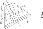
- FIG. 2 a side view of a nose cone and radar antenna system according to an exemplary embodiment is shown.
- the nose cone defines a generally unused annular space 200
- a plurality of actively driven radiating horns 202, 204 are disposed in the annular space 200.
- the radiating horns 202, 204 may be angularly disposed about a central axis defined by the nose cone, including a central space 206 that may house electronics for navigational components.
- each radiating hom 202, 204 in a short-wave infrared system may be disposed proximal to an exterior surface 210 of the nose cone such that the remaining material of the nose cone between the radiating horns 202, 204 and open air (both its thickness and dielectric characteristics) is known and can be accounted for when sending and receiving signals.
- the open, radiating portion of the radiating horns 202, 204 may be generally rhombic or quadrilateral.
- nose cone material when fabricating the nose cone with an embedded radar antenna system, nose cone material may be injection molded or otherwise additively manufactured with the radiating horns 202, 204 in place such that the nose cone material may be structural, and hold the radiating horns 202, 204 in place. Additive manufacture may allow the nose cone with embedded radiating horns 202, 204 to be proportioned according to aerodynamic / mechanical considerations.
- a feed layer 208 is disposed at a bottom surface of the nose cone; for example, the feed layer 208 may comprise a metallized ground plane with multi-layered printed circuit boards.
- the feed layer 208 may be configured such that certain radiating horns 202, 204 are dedicated transmitters and other radiating horns 202, 204 are dedicated receivers.
- the feed layer 208 may be configured to switch some or all of the radiating horns 202, 204 between a transmit mode and receive mode.
- the disposition and sequential operation of the radiating horns 202, 204 enable sequential low aiming for the radar on a very limited volumetric platform.
- Embedding the radiating horns 202, 204 in the plastic dielectric material of the nose cone integrates and minimizes the parasitic effect of the plastic. It may be appreciated that completely embedding the radiating horns 202, 204 in the dielectric material of the nose cone provides structural stability and resistance to forces from acceleration.
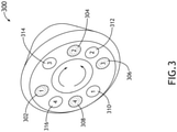
- FIG. 3 a perspective view of a nose cone 300 with representations transmit and receive spacing according to an exemplary embodiment is shown.
- the nose cone 300 includes a plurality of radiating horns angularly disposed in an annular space
- certain of the radiating horns may be activated in a transmit mode while other radiating horns are activated in a receive mode such that radiating horns in different modes are spatially separated to avoid interference from coupling.
- radiating horns are dedicated to either a transmit mode or a receive mode
- radiating horns at different positions 302, 304, 306, 308, 310, 312, 314, 316 are activated in various combinations; for example, a transmit radiating horn in a first transmit position 302 may be activated at the same as a receive radiating horn in a second receive position 312. As radiating horns are sequentially activated, such spacing is maintained to maximize spatial separation.
- frequency-modulated continuous-wave radar systems include separate transmit and receive antennas disposed some distance apart to prevent self-jamming via electromagnetic isolation from spatial separation so that the transmitted signal doesn't lead back into and saturate the receive channel.
- channels may be operating in a counter-rotating fashion.
- Embodiments are suitable for both frequency-modulated continuous-wave radar systems and pulsed radar systems.
- radiating horns may be activated in sequence to produce a circular polarization via horns that can intrinsically generate circular polarization, either by direct generation or by the appropriately phase shifted vertical polarizing and horizontal polarizing horn embodiments. Circular polarization further enhances channel isolation.
- receive and transmit channels are commutated in a synchronous way so as to maximizing separation between transmitting and receiving antennas at any instant in time.
- Certain sequencing may apply only to frequency modulated continuous wave systems. Pulsed systems may only have four radiating horns to maximize aperture size; sequencing may include time-division multiplexing, applicable to both receive and transmit modes.
- receive and transmit channels are commutated asynchronously to improve antenna isolation.
- Embodiments of the disclosed may be extendable to conopulse (2-channel), i.e., 2D Monopulse architectures.
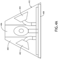
- FIGS. 4A-4B a side view and unfurled view of a nose cone and radar antenna system according to an exemplary embodiment are shown.
- the nose cone defines a generally unused annular space 400
- a plurality of generally ovoid radiating horns 402, 404 are angularly disposed in the annular space 400 about a central axis defined by the nose cone, including a central space 406 that may house electronics for navigational components.
- each radiating horn 402, 404 may be disposed proximal to an exterior surface 410 of the nose cone such that the remaining material of the nose cone between the radiating horns 402, 404 and open air (both its thickness and electromagnetic insulating characteristics) is known and can be accounted for when sending and receiving signals.
- Radiating horns 402, 404 are disposed to maximize surface area for element gain. The use of horn radiating elements allow a wide range of gain / beam width flexibility according to system requirements.
- a feed layer 408 is disposed at a bottom surface of the nose cone.
- the feed layer 408 may be configured such that certain radiating horns 402, 404 are dedicated transmitters and other radiating horns 402, 404 are dedicated receivers.
- the feed layer 408 may be configured to switch some or all of the radiating horns 402, 404 between a transmit mode and receive mode.
- an upper portion of the feed layer 408 is a metalized ground plane that blends into the antenna waveguide feeds.
- a bottom portion of the feed layer 408 is a multi-layered printed circuit board.
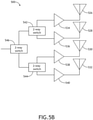
- each radiating horn 504, 506, 507, 510 is in data communication with a corresponding amplifier 512, 514, 516, 518.
- One or more switches 520, 522, 524 allow each radiating horn 504, 506, 507, 510 to be individually addressed.
- each radiating horn 526, 528, 530, 532 is in data communication with a corresponding amplifier 534, 536, 538, 540.
- One or more switches 542, 544, 546 allow each radiating horn 534, 536, 538, 540 to be individually addressed.
- Switches 542, 544, 546 may be RFIC Ka band switches.
- a nose cone includes separate radiating horns 504, 506, 507, 510, 534, 536, 538, 540 and corresponding hardware to simultaneously operate in a receive mode 500 and a transmit mode 502.
- the radar antenna system may operate the switches 520, 522, 524, 542, 544, 546 such that active receive mode 500 radiating horns 504, 506, 507, 510 and active transmit mode 502 radiating horns 534, 536, 538, 540 are spatially separated to prevent interference from coupling.
- the operation of receive mode 500 switches 520, 522, 524 may be algorithmically linked to the operation of transmit mode 502 switches 542, 544, 546 to maintain such spatial separation.
- the receive channel comprises radiating horns 604, 606, 607, 610, each in data communication with a corresponding amplifier 612, 614, 616, 618 and one or more switches 620, 622, 624 to allow each radiating horn 604, 606, 607, 610 to be individually addressed.
- the transmit channel comprises radiating horns 626, 628, 630, 632, each in data communication with a corresponding amplifier 634, 636, 638, 640 and one or more switches 642, 644, 646 to allow each radiating horn 634, 636, 638, 640 to be individually addressed.
- the receive channel radiating horns 604, 606, 607, 610 may be interleaved with the transmit channel radiating horns 626, 628, 630, 632 in their angular disposition about a central axis of a nose cone.
- the radar antenna system 600 may operate the switches 620, 622, 624, 642, 644, 646 such that active receive mode 600 radiating horns 604, 606, 607, 610 and active transmit mode 602 radiating horns 634, 636, 638, 640 are spatially separated to prevent interference from coupling.
- the operation of receive mode 600 switches 620, 622, 624 may be algorithmically linked to the operation of transmit mode 602 switches 642, 644, 646 to maintain such spatial separation.
- each mode switch system 702 comprises a feeder transmit / receive switch 712 connected to one or more switches 720, 722, 724 connecting the switchable radar antenna system 700 to a feed layer, a receive amplifier 716, and a transmit amplifier 718.
- the feeder transmit / receive switch 712 places the corresponding radiating horn channel in either a transmit mode or receive mode.
- a radiating horn transmit / receive switch 714 may also be employed to isolate the transmit channel from the receive channel for each radiating horn 704, 706, 708, 710.
- Each radiating horn 704, 706, 708, 710 may be operated in a receive mode or transmit mode, independently of the other radiating horn 704, 706, 708, 710.
- Embodiments of the present disclosure enable long range targeting outside of the short-wave infrared operational range and conical scan / sequential lobing for a precision target tracking system.
- Antenna systems according to exemplary embodiment are compatible with either frequency modulated continuous wave radar or pulsed radar architectures.
Landscapes
- Engineering & Computer Science (AREA)
- Remote Sensing (AREA)
- Radar, Positioning & Navigation (AREA)
- General Physics & Mathematics (AREA)
- Physics & Mathematics (AREA)
- Chemical & Material Sciences (AREA)
- Computer Networks & Wireless Communication (AREA)
- Combustion & Propulsion (AREA)
- General Engineering & Computer Science (AREA)
- Astronomy & Astrophysics (AREA)
- Aviation & Aerospace Engineering (AREA)
- Variable-Direction Aerials And Aerial Arrays (AREA)
- Radar Systems Or Details Thereof (AREA)
Abstract
Description
- Very small airframes, such as missiles or other munitions, present a challenge when integrating radar systems. Such airframes provide very limited space to house such systems, and the operating environment is hostile to sensitive electronic components. It would be desirable to have a millimeter scale radar antenna system collated with and complementary to a short-wave infrared target location imaging system that is environmentally robust, and that does not compromise the aerodynamics of the platform.
- In one aspect, embodiments of the inventive concepts disclosed herein are directed to a radar antenna having a plurality of horns in the annular space of a munition nose cone. The horns are disposed near the exterior surface of the nose cone. In a further aspect, the nose cone may be injection molded or additively manufactured so that the horns are embedded a known distance from the exterior surface.
- In a further aspect, the horns placed in either a transmit mode or a receive mode so as to maintain a minimum special separation between transmitting horns and receiving horns.
- It is to be understood that both the foregoing general description and the following detailed description are exemplary and explanatory only and should not restrict the scope of the claims. The accompanying drawings, which are incorporated in and constitute a part of the specification, illustrate exemplary embodiments of the inventive concepts disclosed herein and together with the general description, serve to explain the principles.
- The numerous advantages of the embodiments of the inventive concepts disclosed herein may be better understood by those skilled in the art by reference to the accompanying figures in which:
-
FIG. 1 shows a perspective view of a nose cone suitable for use in exemplary embodiments; -
FIG. 2 shows a side view of a nose cone and radar antenna system according to an exemplary embodiment; -
FIG. 3 shows a perspective view of a nose cone with representations transmit and receive spacing according to an exemplary embodiment; -
FIG. 4A shows a side view of a nose cone and radar antenna system according to an exemplary embodiment; -
FIG. 4B shows an unfurled view of a nose cone and radar antenna system according to an exemplary embodiment; -
FIG. 5A shows a block representation of a radar antenna system in a receive mode according to an exemplary embodiment; -
FIG. 5B shows a block representation of a radar antenna system in a transmit mode according to an exemplary embodiment; -
FIG. 6 shows a block representation of a radar antenna system with transmit and receive channels; -
FIG. 7 shows a block representation of a switchable radar antenna system; - Before explaining at least one embodiment of the inventive concepts disclosed herein in detail, it is to be understood that the inventive concepts are not limited in their application to the details of construction and the arrangement of the components or steps or methodologies set forth in the following description or illustrated in the drawings. In the following detailed description of embodiments of the instant inventive concepts, numerous specific details are set forth in order to provide a more thorough understanding of the inventive concepts. However, it will be apparent to one of ordinary skill in the art having the benefit of the instant disclosure that the inventive concepts disclosed herein may be practiced without these specific details. In other instances, well-known features may not be described in detail to avoid unnecessarily complicating the instant disclosure. The inventive concepts disclosed herein are capable of other embodiments or of being practiced or carried out in various ways. Also, it is to be understood that the phraseology and terminology employed herein is for the purpose of description and should not be regarded as limiting.
- As used herein a letter following a reference numeral is intended to reference an embodiment of the feature or element that may be similar, but not necessarily identical, to a previously described element or feature bearing the same reference numeral (e.g., 1, 1a, 1b). Such shorthand notations are used for purposes of convenience only, and should not be construed to limit the inventive concepts disclosed herein in any way unless expressly stated to the contrary.
- Further, unless expressly stated to the contrary, "or" refers to an inclusive or and not to an exclusive or. For example, a condition A or B is satisfied by anyone of the following: A is true (or present) and B is false (or not present), A is false (or not present) and B is true (or present), and both A and B are true (or present).
- In addition, use of the "a" or "an" are employed to describe elements and components of embodiments of the instant inventive concepts. This is done merely for convenience and to give a general sense of the inventive concepts, and "a" and "an" are intended to include one or at least one and the singular also includes the plural unless it is obvious that it is meant otherwise.
- Finally, as used herein any reference to "one embodiment," or "some embodiments" means that a particular element, feature, structure, or characteristic described in connection with the embodiment is included in at least one embodiment of the inventive concepts disclosed herein. The appearances of the phrase "in some embodiments" in various places in the specification are not necessarily all referring to the same embodiment, and embodiments of the inventive concepts disclosed may include one or more of the features expressly described or inherently present herein, or any combination of sub-combination of two or more such features, along with any other features which may not necessarily be expressly described or inherently present in the instant disclosure.
- Broadly, embodiments of the inventive concepts disclosed herein are directed to a radar antenna having a plurality of horns in the annular space of a munition nose cone. The horns are disposed near the exterior surface of the nose cone. In a further aspect, the nose cone may be injection molded or additively manufactured so that the horns are embedded a known distance from the exterior surface.
- Referring to
FIG. 1 , a perspective view of anose cone 100 suitable for use in exemplary embodiments is shown. Thenose cone 100 may define a generally unused annular space 102 (which may be empty or filled with an inert material) and acentral space 104 that may house certain electronic elements for the corresponding munition guidance system. - Referring to
FIG. 2 , a side view of a nose cone and radar antenna system according to an exemplary embodiment is shown. Where the nose cone defines a generally unusedannular space 200, a plurality of actively drivenradiating horns 202, 204 (wave guides) are disposed in theannular space 200. The radiatinghorns central space 206 that may house electronics for navigational components. The open, radiating portion of each radiatinghom exterior surface 210 of the nose cone such that the remaining material of the nose cone between theradiating horns radiating horns horns radiating horns radiating horns - In at least one embodiment, a
feed layer 208 is disposed at a bottom surface of the nose cone; for example, thefeed layer 208 may comprise a metallized ground plane with multi-layered printed circuit boards. Thefeed layer 208 may be configured such that certainradiating horns radiating horns feed layer 208 may be configured to switch some or all of theradiating horns - In at least one embodiment, the disposition and sequential operation of the radiating
horns radiating horns radiating horns - Referring to
FIG. 3 , a perspective view of anose cone 300 with representations transmit and receive spacing according to an exemplary embodiment is shown. Where thenose cone 300 includes a plurality of radiating horns angularly disposed in an annular space, certain of the radiating horns may be activated in a transmit mode while other radiating horns are activated in a receive mode such that radiating horns in different modes are spatially separated to avoid interference from coupling. In at least one embodiment, where radiating horns are dedicated to either a transmit mode or a receive mode, radiating horns atdifferent positions first transmit position 302 may be activated at the same as a receive radiating horn in asecond receive position 312. As radiating horns are sequentially activated, such spacing is maintained to maximize spatial separation. - State of the art frequency-modulated continuous-wave radar systems include separate transmit and receive antennas disposed some distance apart to prevent self-jamming via electromagnetic isolation from spatial separation so that the transmitted signal doesn't lead back into and saturate the receive channel. By operating the radiating horns sequentially in a clockwise or anticlockwise fashion, a sequential lobing radiation pattern may be generated while maintaining spatial separation. In at least one embodiment, channels may be operating in a counter-rotating fashion. Embodiments are suitable for both frequency-modulated continuous-wave radar systems and pulsed radar systems.
- In at least one embodiment, radiating horns may be activated in sequence to produce a circular polarization via horns that can intrinsically generate circular polarization, either by direct generation or by the appropriately phase shifted vertical polarizing and horizontal polarizing horn embodiments. Circular polarization further enhances channel isolation.
- In at least one embodiment, receive and transmit channels are commutated in a synchronous way so as to maximizing separation between transmitting and receiving antennas at any instant in time. Certain sequencing may apply only to frequency modulated continuous wave systems. Pulsed systems may only have four radiating horns to maximize aperture size; sequencing may include time-division multiplexing, applicable to both receive and transmit modes. In at least one embodiment, In at least one embodiment, receive and transmit channels are commutated asynchronously to improve antenna isolation.
- Signal strength varies as a function of beam switching and pattern gain. Embodiments of the disclosed may be extendable to conopulse (2-channel), i.e., 2D Monopulse architectures.
- Referring to
FIGS. 4A-4B , a side view and unfurled view of a nose cone and radar antenna system according to an exemplary embodiment are shown. Where the nose cone defines a generally unusedannular space 400, a plurality of generally ovoid radiatinghorns annular space 400 about a central axis defined by the nose cone, including acentral space 406 that may house electronics for navigational components. The ovoid, open, radiating portion of each radiatinghorn exterior surface 410 of the nose cone such that the remaining material of the nose cone between the radiatinghorns horns - In at least one embodiment, a
feed layer 408 is disposed at a bottom surface of the nose cone. Thefeed layer 408 may be configured such that certain radiatinghorns horns feed layer 408 may be configured to switch some or all of the radiatinghorns feed layer 408 is a metalized ground plane that blends into the antenna waveguide feeds. A bottom portion of thefeed layer 408 is a multi-layered printed circuit board. - Referring to
FIG. 5A-5B , block representations of a radar antenna system in a receivemode 500 and transmit mode 502 according to an exemplary embodiment is shown. In a receivemode 500, each radiatinghorn corresponding amplifier more switches horn horn corresponding amplifier more switches horn Switches - In at least one embodiment, a nose cone includes
separate radiating horns mode 500 and a transmit mode 502. The radar antenna system may operate theswitches mode 500 radiatinghorns horns mode 500switches switches - Referring to
FIG. 6 , a block representation of aradar antenna system 600 with transmit and receive channels is shown. The receive channel comprises radiatinghorns corresponding amplifier more switches horn horns corresponding amplifier more switches horn channel radiating horns channel radiating horns - In at least one embodiment, the
radar antenna system 600 may operate theswitches mode 600 radiatinghorns horns mode 600switches switches - Referring to
FIG. 7 , a block representation of a switchableradar antenna system 700 is shown. The switchableradar antenna system 700 includes a plurality of radiatinghorns mode switch system 702. In at least one embodiment, eachmode switch system 702 comprises a feeder transmit / receiveswitch 712 connected to one ormore switches radar antenna system 700 to a feed layer, a receiveamplifier 716, and a transmitamplifier 718. The feeder transmit / receiveswitch 712 places the corresponding radiating horn channel in either a transmit mode or receive mode. In at least one embodiment, a radiating horn transmit / receiveswitch 714 may also be employed to isolate the transmit channel from the receive channel for each radiatinghorn horn other radiating horn - Embodiments of the present disclosure enable long range targeting outside of the short-wave infrared operational range and conical scan / sequential lobing for a precision target tracking system. Antenna systems according to exemplary embodiment are compatible with either frequency modulated continuous wave radar or pulsed radar architectures.
- It is believed that the inventive concepts disclosed herein and many of their attendant advantages will be understood by the foregoing description of embodiments of the inventive concepts disclosed, and it will be apparent that various changes may be made in the form, construction, and arrangement of the components thereof without departing from the broad scope of the inventive concepts disclosed herein or without sacrificing all of their material advantages; and individual features from various embodiments may be combined to arrive at other embodiments. The form herein before described being merely an explanatory embodiment thereof, it is the intention of the following claims to encompass and include such changes. Furthermore, any of the features disclosed in relation to any of the individual embodiments may be incorporated into any other embodiment.
Claims (15)
- A radar antenna comprising:a plurality of radiating horns (402, 404), each disposed around an axis defined by a nose cone (300); anda feed layer (208) connected to each of the radiating horns,wherein:the plurality of radiating horns embedded in a dielectric material comprising the nose cone (300); andthe feed layer (208) is configured to sequentially activate each of the plurality of radiating horns to produce a conical scan / sequential lobing radiation pattern.
- The radar antenna of Claim 1, wherein:a first set of radiating horns and corresponding feed layer circuitry is dedicated to a sequential receive channel; anda second set of radiating horns and corresponding feed layer circuitry is dedicated to a sequential transmit channel.
- The radar antenna of Claim 2, wherein the feed layer (208) is configured to simultaneously activate radiating horns in the first set and radiating horns in the second set, wherein the activated radiating horns are sufficiently spatially separated to minimize coupling.
- The radar antenna of Claim 3, wherein radiating horns are activated asynchronously.
- The radar antenna of Claim 2, wherein the radar antenna is configured as a frequency modulated continuous wave radar.
- The radar antenna of any preceding Claim, wherein the feed layer is configured to switchably activate each radiating horn in either a transmit mode or a receive mode.
- The radar antenna of Claim 6, wherein the radar antenna is configured as a pulsed radar.
- A nose cone comprising:a plurality of radiating horns (402, 404), each disposed in an annular space around an axis defined by the nose cone; anda feed layer (208) connected to each of the radiating horns,wherein:the plurality of radiating horns (402, 404) embedded in a dielectric material comprising the node cone; andthe feed layer (208) is configured to sequentially activate each of the plurality of radiating horns to produce a conical scan / sequential lobing radiation pattern.
- The nose cone of Claim 8, wherein:a first set of radiating horns and corresponding feed layer circuitry is dedicated to a sequential receive channel; anda second set of radiating horns and corresponding feed layer circuitry is dedicated to a sequential transmit channel.
- The nose cone of Claim 9, wherein the feed layer is configured to simultaneously activate radiating horns in the first set and radiating horns in the second set, wherein the activated radiating horns are sufficiently spatially separated to minimize coupling.
- The nose cone of Claim 10, wherein radiating horns are activated asynchronously.
- The nose cone of Claim 10, wherein the first set and second set are sequenced in a counter-rotating fashion.
- The nose cone of Claim 9, wherein the radar antenna is configured as a frequency modulated continuous wave radar.
- The nose cone of Claim 8, wherein the feed layer is configured to switchably activate each radiating horn in either a transmit mode or a receive mode.
- The nose cone of Claim 14, wherein the radar antenna is configured as a pulsed radar.
Applications Claiming Priority (1)
| Application Number | Priority Date | Filing Date | Title |
|---|---|---|---|
| US17/024,364 US11598867B2 (en) | 2020-09-17 | 2020-09-17 | Seeker sequential lobing radar antenna system |
Publications (1)
| Publication Number | Publication Date |
|---|---|
| EP3972056A1 true EP3972056A1 (en) | 2022-03-23 |
Family
ID=77838707
Family Applications (1)
| Application Number | Title | Priority Date | Filing Date |
|---|---|---|---|
| EP21197517.2A Pending EP3972056A1 (en) | 2020-09-17 | 2021-09-17 | Seeker sequential lobing radar antenna system |
Country Status (2)
| Country | Link |
|---|---|
| US (1) | US11598867B2 (en) |
| EP (1) | EP3972056A1 (en) |
Families Citing this family (2)
| Publication number | Priority date | Publication date | Assignee | Title |
|---|---|---|---|---|
| DE102022004208A1 (en) * | 2022-11-14 | 2024-05-16 | MBDA DeutschIand GmbH | Conformal MIMO radar antennas to reduce drag in missile applications |
| DE102022004209A1 (en) * | 2022-11-14 | 2024-05-16 | Mbda Deutschland Gmbh | Symmetrical antenna arrangements and associated methods for determining radiation patterns |
Citations (4)
| Publication number | Priority date | Publication date | Assignee | Title |
|---|---|---|---|---|
| US20040263387A1 (en) * | 1992-09-11 | 2004-12-30 | Ball Aerospace & Technologies Corp. | Electronically agile dual beam antenna system |
| KR100687908B1 (en) * | 2005-03-16 | 2007-02-27 | (주) 아이엔텍 | Pyramid Horn Antenna for Radar Detector Using Trapezoidal Waveguide |
| US20180013203A1 (en) * | 2016-04-06 | 2018-01-11 | Raytheon Company | Conformal broadband directional 1/2 flared notch radiator antenna array |
| US20190198985A1 (en) * | 2017-12-26 | 2019-06-27 | Nxp Usa, Inc. | Unmanned vehicle radar system |
Family Cites Families (18)
| Publication number | Priority date | Publication date | Assignee | Title |
|---|---|---|---|---|
| US3243804A (en) * | 1963-07-26 | 1966-03-29 | Jr Ira D Smith | Four horn sequential lobing radar |
| US3755815A (en) | 1971-12-20 | 1973-08-28 | Sperry Rand Corp | Phased array fed lens antenna |
| US4665401A (en) * | 1980-10-10 | 1987-05-12 | Sperry Corporation | Millimeter wave length guidance system |
| US4491845A (en) | 1982-11-23 | 1985-01-01 | The United States Of America As Represented By The Secretary Of The Air Force | Wide angle phased array dome lens antenna with a reflection/transmission switch |
| GB2252207B (en) | 1985-03-19 | 1992-12-16 | British Aerospace | Integrated antenna/mixer devices and weapon guidance systems |
| US5520356A (en) * | 1992-08-14 | 1996-05-28 | Ensley; Donald L. | System for propelling and guiding a solid object with a beam of electromagnetic radiation |
| US6703982B2 (en) | 2001-08-22 | 2004-03-09 | Raytheon Company | Conformal two dimensional electronic scan antenna with butler matrix and lens ESA |
| US7834803B2 (en) * | 2008-09-03 | 2010-11-16 | Lockheed Martin Corporation | Electronically steered, dual-polarized, dual-plane, monopulse antenna feed |
| EP2359437B1 (en) | 2008-11-12 | 2013-10-16 | Saab AB | Method and arrangement for a low radar cross section antenna |
| US8497812B2 (en) | 2009-01-30 | 2013-07-30 | Raytheon Company | Composite radome and radiator structure |
| US9091745B2 (en) | 2012-02-20 | 2015-07-28 | Rockwell Collins, Inc. | Optimized two panel AESA for aircraft applications |
| US9118112B1 (en) | 2013-03-14 | 2015-08-25 | Rockwell Collins, Inc. | Multi-sensor system and method for vehicles |
| IL232381B (en) | 2014-04-30 | 2020-02-27 | Israel Aerospace Ind Ltd | Cover |
| US10663576B2 (en) | 2016-04-20 | 2020-05-26 | Saab Ab | Method for controlling transmission of an electronically steerable antenna system and such electronically steerable antenna system |
| US10224629B2 (en) | 2016-05-20 | 2019-03-05 | Rockwell Collins, Inc. | Systems and methods for ultra-ultra-wide band AESA |
| US10288395B1 (en) | 2016-06-09 | 2019-05-14 | The United States Of America As Represented By The Secretary Of The Army | Nosecone inverted F antenna for S-band telemetry |
| GB201611020D0 (en) | 2016-06-24 | 2016-08-10 | Bae Systems Plc | Aircraft radar assembly |
| EP3476005B1 (en) | 2016-06-24 | 2024-08-28 | BAE Systems PLC | Aircraft radar assembly |
-
2020
- 2020-09-17 US US17/024,364 patent/US11598867B2/en active Active
-
2021
- 2021-09-17 EP EP21197517.2A patent/EP3972056A1/en active Pending
Patent Citations (4)
| Publication number | Priority date | Publication date | Assignee | Title |
|---|---|---|---|---|
| US20040263387A1 (en) * | 1992-09-11 | 2004-12-30 | Ball Aerospace & Technologies Corp. | Electronically agile dual beam antenna system |
| KR100687908B1 (en) * | 2005-03-16 | 2007-02-27 | (주) 아이엔텍 | Pyramid Horn Antenna for Radar Detector Using Trapezoidal Waveguide |
| US20180013203A1 (en) * | 2016-04-06 | 2018-01-11 | Raytheon Company | Conformal broadband directional 1/2 flared notch radiator antenna array |
| US20190198985A1 (en) * | 2017-12-26 | 2019-06-27 | Nxp Usa, Inc. | Unmanned vehicle radar system |
Non-Patent Citations (1)
| Title |
|---|
| SAMANEH ESFANDIARPOUR ET AL: "Wideband planar horn antenna using substrate integrated waveguide technique", MICROWAVE CONFERENCE PROCEEDINGS (APMC), 2011 ASIA-PACIFIC, IEEE, 5 December 2011 (2011-12-05), pages 1969 - 1972, XP032153049, ISBN: 978-1-4577-2034-5 * |
Also Published As
| Publication number | Publication date |
|---|---|
| US11598867B2 (en) | 2023-03-07 |
| US20220082678A1 (en) | 2022-03-17 |
Similar Documents
| Publication | Publication Date | Title |
|---|---|---|
| US6714163B2 (en) | Structurally-integrated, space-fed phased array antenna system for use on an aircraft | |
| US5874915A (en) | Wideband cylindrical UHF array | |
| US6078289A (en) | Array antenna having a dual field of view | |
| US7443334B2 (en) | Collision alerting and avoidance system | |
| KR101779900B1 (en) | Active electronically scanned array radar | |
| CN108039562A (en) | A kind of Active conformal array antenna applied to unmanned aerial vehicle platform | |
| US11598867B2 (en) | Seeker sequential lobing radar antenna system | |
| WO2012109016A2 (en) | Adaptive electronically steerable array (aesa) system for multi-band and multi-aperture operation and method for maintaining data links with one or more stations in different frequency bands | |
| US20100052987A1 (en) | Electronically steered, dual-polarized, dual-plane, monopulse antenna feed | |
| US20200348412A1 (en) | Multiple Beam Antenna for Wide Swath Satellite Based SAR | |
| EP1933163A1 (en) | Improvements to an obstacle sensor operating by collimation and focusing of the emitted wave | |
| CN104682017A (en) | Multi-beam phased-array satellite communication antenna array and directivity control system | |
| CN113471717B (en) | Antenna module and radar | |
| EP3319172A1 (en) | Airborne/spaceborne distributed aperture multi sensing pulsed rf system | |
| JP2025065297A (en) | Conformal/Omnidirectional Differential Sectioned Aperture | |
| US7071872B2 (en) | Common aperture antenna | |
| KR101683679B1 (en) | Conformal Patch Type of Array Antenna | |
| EP2390957A1 (en) | A radar decoy | |
| EP3968455B1 (en) | Missile seeker limited scan array radar antenna | |
| Otten et al. | Circular micro-SAR for mini-UAV | |
| Huizing et al. | Compact scalable multifunction RF payload for UAVs with FMCW radar and ESM functionality | |
| van Bezouwen et al. | Status and trends in AESA-based radar | |
| WO2019235933A1 (en) | Radar antenna for use in a miniature unmanned aerial vehicle | |
| Das | Advances in active radar seeker technology | |
| US11009867B1 (en) | Low-cost distributed multifunction radio frequency (MFRF) swarming unmanned aircraft systems (UAS) |
Legal Events
| Date | Code | Title | Description |
|---|---|---|---|
| PUAI | Public reference made under article 153(3) epc to a published international application that has entered the european phase |
Free format text: ORIGINAL CODE: 0009012 |
|
| STAA | Information on the status of an ep patent application or granted ep patent |
Free format text: STATUS: THE APPLICATION HAS BEEN PUBLISHED |
|
| AK | Designated contracting states |
Kind code of ref document: A1 Designated state(s): AL AT BE BG CH CY CZ DE DK EE ES FI FR GB GR HR HU IE IS IT LI LT LU LV MC MK MT NL NO PL PT RO RS SE SI SK SM TR |
|
| STAA | Information on the status of an ep patent application or granted ep patent |
Free format text: STATUS: REQUEST FOR EXAMINATION WAS MADE |
|
| 17P | Request for examination filed |
Effective date: 20220923 |
|
| RBV | Designated contracting states (corrected) |
Designated state(s): AL AT BE BG CH CY CZ DE DK EE ES FI FR GB GR HR HU IE IS IT LI LT LU LV MC MK MT NL NO PL PT RO RS SE SI SK SM TR |
|
| STAA | Information on the status of an ep patent application or granted ep patent |
Free format text: STATUS: EXAMINATION IS IN PROGRESS |
|
| 17Q | First examination report despatched |
Effective date: 20230602 |
|
| GRAP | Despatch of communication of intention to grant a patent |
Free format text: ORIGINAL CODE: EPIDOSNIGR1 |
|
| STAA | Information on the status of an ep patent application or granted ep patent |
Free format text: STATUS: GRANT OF PATENT IS INTENDED |
|
| INTG | Intention to grant announced |
Effective date: 20260217 |
|
| RIN1 | Information on inventor provided before grant (corrected) |
Inventor name: WEST, JAMES B. Inventor name: PETERS, KEAGAN |