EP3972046A1 - Battery pack having improved safety - Google Patents
Battery pack having improved safety Download PDFInfo
- Publication number
- EP3972046A1 EP3972046A1 EP21738120.1A EP21738120A EP3972046A1 EP 3972046 A1 EP3972046 A1 EP 3972046A1 EP 21738120 A EP21738120 A EP 21738120A EP 3972046 A1 EP3972046 A1 EP 3972046A1
- Authority
- EP
- European Patent Office
- Prior art keywords
- busbar
- battery pack
- thermal insulation
- cover
- terminal unit
- Prior art date
- Legal status (The legal status is an assumption and is not a legal conclusion. Google has not performed a legal analysis and makes no representation as to the accuracy of the status listed.)
- Granted
Links
Images







Classifications
-
- H—ELECTRICITY
- H01—ELECTRIC ELEMENTS
- H01M—PROCESSES OR MEANS, e.g. BATTERIES, FOR THE DIRECT CONVERSION OF CHEMICAL ENERGY INTO ELECTRICAL ENERGY
- H01M50/00—Constructional details or processes of manufacture of the non-active parts of electrochemical cells other than fuel cells, e.g. hybrid cells
- H01M50/50—Current conducting connections for cells or batteries
- H01M50/572—Means for preventing undesired use or discharge
-
- H—ELECTRICITY
- H01—ELECTRIC ELEMENTS
- H01M—PROCESSES OR MEANS, e.g. BATTERIES, FOR THE DIRECT CONVERSION OF CHEMICAL ENERGY INTO ELECTRICAL ENERGY
- H01M10/00—Secondary cells; Manufacture thereof
- H01M10/60—Heating or cooling; Temperature control
- H01M10/65—Means for temperature control structurally associated with the cells
- H01M10/658—Means for temperature control structurally associated with the cells by thermal insulation or shielding
-
- H—ELECTRICITY
- H01—ELECTRIC ELEMENTS
- H01M—PROCESSES OR MEANS, e.g. BATTERIES, FOR THE DIRECT CONVERSION OF CHEMICAL ENERGY INTO ELECTRICAL ENERGY
- H01M50/00—Constructional details or processes of manufacture of the non-active parts of electrochemical cells other than fuel cells, e.g. hybrid cells
- H01M50/20—Mountings; Secondary casings or frames; Racks, modules or packs; Suspension devices; Shock absorbers; Transport or carrying devices; Holders
-
- H—ELECTRICITY
- H01—ELECTRIC ELEMENTS
- H01M—PROCESSES OR MEANS, e.g. BATTERIES, FOR THE DIRECT CONVERSION OF CHEMICAL ENERGY INTO ELECTRICAL ENERGY
- H01M50/00—Constructional details or processes of manufacture of the non-active parts of electrochemical cells other than fuel cells, e.g. hybrid cells
- H01M50/20—Mountings; Secondary casings or frames; Racks, modules or packs; Suspension devices; Shock absorbers; Transport or carrying devices; Holders
- H01M50/233—Mountings; Secondary casings or frames; Racks, modules or packs; Suspension devices; Shock absorbers; Transport or carrying devices; Holders characterised by physical properties of casings or racks, e.g. dimensions
- H01M50/24—Mountings; Secondary casings or frames; Racks, modules or packs; Suspension devices; Shock absorbers; Transport or carrying devices; Holders characterised by physical properties of casings or racks, e.g. dimensions adapted for protecting batteries from their environment, e.g. from corrosion
-
- H—ELECTRICITY
- H01—ELECTRIC ELEMENTS
- H01M—PROCESSES OR MEANS, e.g. BATTERIES, FOR THE DIRECT CONVERSION OF CHEMICAL ENERGY INTO ELECTRICAL ENERGY
- H01M50/00—Constructional details or processes of manufacture of the non-active parts of electrochemical cells other than fuel cells, e.g. hybrid cells
- H01M50/20—Mountings; Secondary casings or frames; Racks, modules or packs; Suspension devices; Shock absorbers; Transport or carrying devices; Holders
- H01M50/258—Modular batteries; Casings provided with means for assembling
-
- H—ELECTRICITY
- H01—ELECTRIC ELEMENTS
- H01M—PROCESSES OR MEANS, e.g. BATTERIES, FOR THE DIRECT CONVERSION OF CHEMICAL ENERGY INTO ELECTRICAL ENERGY
- H01M50/00—Constructional details or processes of manufacture of the non-active parts of electrochemical cells other than fuel cells, e.g. hybrid cells
- H01M50/50—Current conducting connections for cells or batteries
- H01M50/502—Interconnectors for connecting terminals of adjacent batteries; Interconnectors for connecting cells outside a battery casing
-
- H—ELECTRICITY
- H01—ELECTRIC ELEMENTS
- H01M—PROCESSES OR MEANS, e.g. BATTERIES, FOR THE DIRECT CONVERSION OF CHEMICAL ENERGY INTO ELECTRICAL ENERGY
- H01M50/00—Constructional details or processes of manufacture of the non-active parts of electrochemical cells other than fuel cells, e.g. hybrid cells
- H01M50/50—Current conducting connections for cells or batteries
- H01M50/502—Interconnectors for connecting terminals of adjacent batteries; Interconnectors for connecting cells outside a battery casing
- H01M50/503—Interconnectors for connecting terminals of adjacent batteries; Interconnectors for connecting cells outside a battery casing characterised by the shape of the interconnectors
-
- H—ELECTRICITY
- H01—ELECTRIC ELEMENTS
- H01M—PROCESSES OR MEANS, e.g. BATTERIES, FOR THE DIRECT CONVERSION OF CHEMICAL ENERGY INTO ELECTRICAL ENERGY
- H01M50/00—Constructional details or processes of manufacture of the non-active parts of electrochemical cells other than fuel cells, e.g. hybrid cells
- H01M50/50—Current conducting connections for cells or batteries
- H01M50/502—Interconnectors for connecting terminals of adjacent batteries; Interconnectors for connecting cells outside a battery casing
- H01M50/505—Interconnectors for connecting terminals of adjacent batteries; Interconnectors for connecting cells outside a battery casing comprising a single busbar
-
- H—ELECTRICITY
- H01—ELECTRIC ELEMENTS
- H01M—PROCESSES OR MEANS, e.g. BATTERIES, FOR THE DIRECT CONVERSION OF CHEMICAL ENERGY INTO ELECTRICAL ENERGY
- H01M50/00—Constructional details or processes of manufacture of the non-active parts of electrochemical cells other than fuel cells, e.g. hybrid cells
- H01M50/50—Current conducting connections for cells or batteries
- H01M50/502—Interconnectors for connecting terminals of adjacent batteries; Interconnectors for connecting cells outside a battery casing
- H01M50/507—Interconnectors for connecting terminals of adjacent batteries; Interconnectors for connecting cells outside a battery casing comprising an arrangement of two or more busbars within a container structure, e.g. busbar modules
-
- H—ELECTRICITY
- H01—ELECTRIC ELEMENTS
- H01M—PROCESSES OR MEANS, e.g. BATTERIES, FOR THE DIRECT CONVERSION OF CHEMICAL ENERGY INTO ELECTRICAL ENERGY
- H01M50/00—Constructional details or processes of manufacture of the non-active parts of electrochemical cells other than fuel cells, e.g. hybrid cells
- H01M50/50—Current conducting connections for cells or batteries
- H01M50/543—Terminals
-
- H—ELECTRICITY
- H01—ELECTRIC ELEMENTS
- H01M—PROCESSES OR MEANS, e.g. BATTERIES, FOR THE DIRECT CONVERSION OF CHEMICAL ENERGY INTO ELECTRICAL ENERGY
- H01M50/00—Constructional details or processes of manufacture of the non-active parts of electrochemical cells other than fuel cells, e.g. hybrid cells
- H01M50/50—Current conducting connections for cells or batteries
- H01M50/572—Means for preventing undesired use or discharge
- H01M50/584—Means for preventing undesired use or discharge for preventing incorrect connections inside or outside the batteries
- H01M50/59—Means for preventing undesired use or discharge for preventing incorrect connections inside or outside the batteries characterised by the protection means
-
- H—ELECTRICITY
- H01—ELECTRIC ELEMENTS
- H01R—ELECTRICALLY-CONDUCTIVE CONNECTIONS; STRUCTURAL ASSOCIATIONS OF A PLURALITY OF MUTUALLY-INSULATED ELECTRICAL CONNECTING ELEMENTS; COUPLING DEVICES; CURRENT COLLECTORS
- H01R13/00—Details of coupling devices of the kinds covered by groups H01R12/70 or H01R24/00 - H01R33/00
- H01R13/46—Bases; Cases
- H01R13/52—Dustproof, splashproof, drip-proof, waterproof, or flameproof cases
-
- H—ELECTRICITY
- H01—ELECTRIC ELEMENTS
- H01R—ELECTRICALLY-CONDUCTIVE CONNECTIONS; STRUCTURAL ASSOCIATIONS OF A PLURALITY OF MUTUALLY-INSULATED ELECTRICAL CONNECTING ELEMENTS; COUPLING DEVICES; CURRENT COLLECTORS
- H01R4/00—Electrically-conductive connections between two or more conductive members in direct contact, i.e. touching one another; Means for effecting or maintaining such contact; Electrically-conductive connections having two or more spaced connecting locations for conductors and using contact members penetrating insulation
- H01R4/28—Clamped connections, spring connections
- H01R4/30—Clamped connections, spring connections utilising a screw or nut clamping member
- H01R4/302—Clamped connections, spring connections utilising a screw or nut clamping member having means for preventing loosening of screw or nut, e.g. vibration-proof connection
-
- H—ELECTRICITY
- H01—ELECTRIC ELEMENTS
- H01M—PROCESSES OR MEANS, e.g. BATTERIES, FOR THE DIRECT CONVERSION OF CHEMICAL ENERGY INTO ELECTRICAL ENERGY
- H01M2200/00—Safety devices for primary or secondary batteries
-
- H—ELECTRICITY
- H01—ELECTRIC ELEMENTS
- H01M—PROCESSES OR MEANS, e.g. BATTERIES, FOR THE DIRECT CONVERSION OF CHEMICAL ENERGY INTO ELECTRICAL ENERGY
- H01M2220/00—Batteries for particular applications
- H01M2220/10—Batteries in stationary systems, e.g. emergency power source in plant
-
- H—ELECTRICITY
- H01—ELECTRIC ELEMENTS
- H01M—PROCESSES OR MEANS, e.g. BATTERIES, FOR THE DIRECT CONVERSION OF CHEMICAL ENERGY INTO ELECTRICAL ENERGY
- H01M2220/00—Batteries for particular applications
- H01M2220/20—Batteries in motive systems, e.g. vehicle, ship, plane
-
- H—ELECTRICITY
- H01—ELECTRIC ELEMENTS
- H01M—PROCESSES OR MEANS, e.g. BATTERIES, FOR THE DIRECT CONVERSION OF CHEMICAL ENERGY INTO ELECTRICAL ENERGY
- H01M2220/00—Batteries for particular applications
- H01M2220/30—Batteries in portable systems, e.g. mobile phone, laptop
-
- Y—GENERAL TAGGING OF NEW TECHNOLOGICAL DEVELOPMENTS; GENERAL TAGGING OF CROSS-SECTIONAL TECHNOLOGIES SPANNING OVER SEVERAL SECTIONS OF THE IPC; TECHNICAL SUBJECTS COVERED BY FORMER USPC CROSS-REFERENCE ART COLLECTIONS [XRACs] AND DIGESTS
- Y02—TECHNOLOGIES OR APPLICATIONS FOR MITIGATION OR ADAPTATION AGAINST CLIMATE CHANGE
- Y02E—REDUCTION OF GREENHOUSE GAS [GHG] EMISSIONS, RELATED TO ENERGY GENERATION, TRANSMISSION OR DISTRIBUTION
- Y02E60/00—Enabling technologies; Technologies with a potential or indirect contribution to GHG emissions mitigation
- Y02E60/10—Energy storage using batteries
Definitions
- a plurality of battery cells is electrically connected to each other so as to be used as a single battery in a general way.
- a plurality of battery cells be electrically connected to each other in series or in parallel to form a battery module and a plurality of battery modules be received in a battery case so as to be used in the form of a battery pack.
- the bolt cover 40 does not protect the terminal unit 20 and a busbar assembly 50 coupled to electrode leads of the submodule 10.
- heat may be transferred through a connection region between the terminal unit 20 and the connection busbar 30, which are exposed more than the other regions, whereby fire may easily occur in succession.
- a conductive pollutant discharged from a module damaged due to fire may permeate into the connection region between the terminal unit 20 and the connection busbar 30, whereby the submodule 10 may be damaged or open-circuited and thus fire may be caused.
- the thermal insulation cover may include an upper end cover provided at the upper part of the battery pack at which the busbar assembly and the blocking structure are located and a side cover provided at a different submodule facing portion of the busbar assembly.
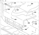
- FIG. 2 is a perspective view of a battery pack according to a first preferred embodiment of the present invention
- FIG. 3 is a perspective view of a blocking structure according to the first preferred embodiment of the present invention when viewed from the rear
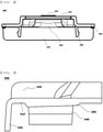
- FIG. 4 is a front view of the blocking structure according to the first preferred embodiment of the present invention
- FIG. 5 is a side view of the blocking structure according to the first preferred embodiment of the present invention.
- the blocking structure 400 may be made of an insulation material that exhibits chemical resistance and thermal insulation in order to prevent the submodule 100 from being damaged by fire in an adjacent submodule or a pollutant. Any material that can be used in a battery may be used as the insulation material that exhibits chemical resistance and thermal insulation. In consideration of use of the battery pack, however, a material that is light and generates no toxic substance is preferably used.
- FIG. 7 is a perspective view of a thermal insulation cover 800 provided in a battery pack according to a third preferred embodiment of the present invention.
- the thermal insulation cover 800 is configured to protect the blocking structure 400.
- a structure configured to protect a general terminal cover without the blocking structure 400 is also possible.
- the upper part of the side cover 820 is configured to have a flat plate shape, in the same manner as the upper part of the upper end cover 810, and the lower part of the side cover is configured to have a shape corresponding to a coupling region.
- the size of the side cover 820 may be equal to or greater than the size of the side structure 430 of the blocking structure 400.
- the blocking structure 400 may have a size capable of protecting the busbar assembly 500 and the electrode terminals of the submodule 100.
- the thermal insulation cover 800 may further include a rear cover 840 provided parallel to the side cover 820, the rear cover being configured to protect the connection busbar 300 and the rear surface of the blocking structure 400.
- the rear cover 840 may be configured to have a shape that protects a portion that is not protected by the connection busbar 300, as shown in FIG. 10 , or may have a long plate shape configured to protect the connection busbar 300.
- the rear cover 840 according to the present invention may have a structure configured to also protect a side surface portion of the blocking structure adjacent to the rear surface thereof, as shown in FIG. 10 . This structure is a structure prepared for the case in which some of fire is separated from the main current of fire and returns back.
Landscapes
- Chemical & Material Sciences (AREA)
- Chemical Kinetics & Catalysis (AREA)
- Electrochemistry (AREA)
- General Chemical & Material Sciences (AREA)
- Engineering & Computer Science (AREA)
- Manufacturing & Machinery (AREA)
- Connection Of Batteries Or Terminals (AREA)
- Battery Mounting, Suspending (AREA)
- Secondary Cells (AREA)
Abstract
Description
- This application claims the benefit of priority to
Korean Patent Application No. 2020-0001345 filed on January 6, 2020 - The present invention relates to a battery pack with improved safety and a secondary battery including the same, and more particularly to a battery pack including two or more submodules, in each of which a plurality of unit cells, each of which includes an electrode assembly and an electrode lead protruding from the electrode assembly, is disposed, a pack case configured to receive the submodules, a busbar assembly including a busbar configured to electrically connect the electrode leads of the submodules to each other and a busbar frame connected to the busbar, a connection busbar configured to connect the submodules to each other, a terminal unit constituted by a cluster of electrode leads electrically connected to each other via the busbar, the terminal unit being connected to the connection busbar, and a blocking structure configured to wrap the terminal unit, the busbar assembly, and the upper end and the side surface of the connection busbar at the portion thereof connected to the terminal unit, and a secondary battery including the same.
- With technological development of mobile devices, such as mobile phones, laptop computers, camcorders, and digital cameras, and an increase in demand therefor, research on secondary batteries, which are capable of being charged and discharged, has been actively conducted. In addition, secondary batteries, which are energy sources substituting for fossil fuels causing air pollution, have been applied to an electric vehicle (EV), a hybrid electric vehicle (HEV), and a plug-in hybrid electric vehicle (P-HEV), and therefore there is an increasing necessity for development of high-capacity, high-efficiency secondary batteries.
- With an increase in demand for secondary batteries and necessity for high-capacity batteries, various attempts to increase the capacities of the secondary batteries have been made. Although there is a case in which the capacity of one battery cell is increased and used, a plurality of battery cells is electrically connected to each other so as to be used as a single battery in a general way. In general, it is preferable that a plurality of battery cells be electrically connected to each other in series or in parallel to form a battery module and a plurality of battery modules be received in a battery case so as to be used in the form of a battery pack.
- For a high-capacity battery or a battery pack, however, it is difficult to cool the battery, compared to a single battery cell, whereby there is a higher danger of thermal runaway, fire, or explosion. In order to improve overall safety of the battery pack, therefore, a separate alarm system may be provided or a cooling or fire extinguishing construction may be added.
- A separate member may be added to the battery pack or the structure of the battery pack may be changed in order to secure safety of the battery pack. However, this configuration is provided to prevent fire breakout in or abnormal operation of an abnormal battery module, and a configuration capable of preventing spread of fire to a module adjacent to an abnormal battery module to thus prevent transfer of thermal runaway is not considered.
-
FIG. 1 is a perspective view of a conventional battery pack. The conventional battery pack includes two ormore submodules 10, in each of which a plurality of unit cells is disposed, aterminal unit 20 constituted by a cluster of electrode leads of thesubmodule 10, and aconnection busbar 30 configured to connect thesubmodules 10 to each other, wherein theterminal unit 20 and theconnection busbar 30 are covered by abolt cover 40 so as to be insulated. - The
bolt cover 40, which is provided for insulation, only covers a portion of theterminal unit 20 and theconnection busbar 30 connected thereto, in the form of a plate, or is provided in the form of a cap fitted to theterminal unit 20, as shown inFIG. 1 . - However, the
bolt cover 40 does not protect theterminal unit 20 and abusbar assembly 50 coupled to electrode leads of thesubmodule 10. Particularly, in the case in which fire breaks out in an adjacent module of the conventional battery pack ofFIG. 1 , heat may be transferred through a connection region between theterminal unit 20 and theconnection busbar 30, which are exposed more than the other regions, whereby fire may easily occur in succession. In addition, a conductive pollutant discharged from a module damaged due to fire may permeate into the connection region between theterminal unit 20 and theconnection busbar 30, whereby thesubmodule 10 may be damaged or open-circuited and thus fire may be caused. - Patent Document 1 provides a terminal cover configured to protect an electrode terminal unit. However, this is provided for connection with an external device. In addition, the terminal cover of Patent Document 1 is configured in the form of a cap capable of covering only a terminal, and the cap is provided with only an O-ring for each attachment and detachment. However, a structure capable of protecting the electrode terminal unit from fire or a pollutant is not provided.
-
Patent Document 2 provides a terminal cover configured to protect an electrode terminal unit, wherein the terminal cover is made of a soft material that can be elastically deformed. However, the terminal cover is not a structure capable of protecting the terminal unit from fire or a pollutant. In addition, the terminal cover is a construction configured to protect a terminal outside a battery pack but is not a construction configured to protect a connection portion between battery modules. - Therefore, there is a need for a construction capable of preventing transfer of thermal runaway between submodules in a battery pack and protecting a battery module from the outside.
-
- (Patent Document 1)
Korean Patent Application Publication No. 2018-0058552 - (Patent Document 2)
Korean Patent Application Publication No. 2019-0088675 - The present invention has been made in view of the above problems, and it is an object of the present invention to protect submodules by wrapping an exposed region of each submodule using a blocking structure configured to protect a terminal unit of the submodule, a connection busbar configured to electrically connect the submodules to each other, and a busbar assembly.
- It is another object of the present invention to prevent an adjacent submodule from being affected when a specific submodule is abnormal by manufacturing the blocking structure using a material that exhibits heat resistance and chemical resistance.
- It is a further object of the present invention to prevent the occurrence of fire or explosion in succession by protecting each submodule, thereby preventing pecuniary and non-pecuniary losses.
- In order to accomplish the above objects, a battery pack according to the present invention includes two or more submodules, each of the two or more submodules having a plurality of unit cells, each of the plurality of unit cells comprising an electrode assembly and an electrode lead protruding from the electrode assembly, a pack case configured to receive the submodules, a busbar assembly including a busbar configured to electrically connect the electrode leads of the submodules to each other and a busbar frame connected to the busbar, a connection busbar configured to connect the submodules to each other, a terminal unit comprising a cluster of the electrode leads electrically connected to each other via the busbar, the terminal unit being connected to the connection busbar, and a blocking structure configured to wrap the terminal unit, the busbar assembly, and the upper end and the side surface of the connection busbar at the portion thereof connected to the terminal unit.
- The blocking structure may be made of an insulation material that exhibits chemical resistance and thermal insulation.
- The insulation material may include silicate.
- The insulation material may include mica or ceramics.
- The blocking structure may include an upper structure configured to have a shape corresponding to the busbar assembly, the upper structure being located at the upper end of the busbar assembly, a terminal protecting portion protruding from the upper structure so as to have a shape corresponding to the terminal unit and the connection busbar, a side structure configured to further protect a different submodule facing portion of the busbar frame, and a pollutant permeation preventing portion located at the lower part of the upper structure, the pollutant permeation preventing portion being configured to protect opposite side surfaces of the terminal unit and opposite side surfaces of the connection busbar.
- The pollutant permeation preventing portion may be coupled to a space between the busbar and the terminal unit and the connection busbar connected thereto.
- The blocking structure may further include a thermal insulation cover configured to protect the blocking structure.
- The thermal insulation cover may include an upper end cover provided at the upper part of the battery pack at which the busbar assembly and the blocking structure are located and a side cover provided at a different submodule facing portion of the busbar assembly.
- The thermal insulation cover may be made of a thermal insulation material.
- The thermal insulation material may include silicate.
- The thermal insulation material may include mica or ceramics.
- The thermal insulation cover may be configured to cover the entirety of the connection busbar.
- The thermal insulation cover may further includes a rear cover provided parallel to the side cover, the rear cover being configured to protect the connection busbar and the rear surface of the blocking structure.
- In addition, the present invention includes a device using the battery pack as an energy source.
- The device may be any one selected from a group consisting of a mobile phone, a tablet computer, a laptop computer, a power tool, a wearable electronic device, an electric vehicle, a hybrid electric vehicle, a plug-in hybrid electric vehicle, and an energy storage system.
- In the present invention, one or more constructions that do not conflict with each other may be selected and combined from among the above constructions.
-
-
FIG. 1 is a perspective view of a conventional battery pack. -
FIG. 2 is a perspective view of a battery pack according to a first preferred embodiment of the present invention. -
FIG. 3 is a perspective view of a blocking structure according to the first preferred embodiment of the present invention when viewed from the rear. -
FIG. 4 is a front view of the blocking structure according to the first preferred embodiment of the present invention. -
FIG. 5 is a side view of the blocking structure according to the first preferred embodiment of the present invention. -
FIG. 6 is a perspective view of a battery pack according to a second preferred embodiment of the present invention. -
FIG. 7 is a perspective view of a thermal insulation cover provided in a battery pack according to a third preferred embodiment of the present invention. -
FIG. 8 is a perspective view of the battery pack according to the third preferred embodiment of the present invention before coupling. -
FIG. 9 is a perspective view of the battery pack according to the third preferred embodiment of the present invention after coupling. -
FIG. 10 is a view showing a modification of the third preferred embodiment of the present invention. -
FIG. 11 is a resistance measurement graph of the battery pack according to the second preferred embodiment of the present invention and Comparative Example. -
FIG. 12 is a schematic view showing the dispositions of submodules for resistance measurement in the battery pack according to the second preferred embodiment of the present invention and Comparative Example. - In the present application, it should be understood that the terms "comprises," "has," "includes," etc. specify the presence of stated features, numbers, steps, operations, elements, components, or combinations thereof, but do not preclude the presence or addition of one or more other features, numbers, steps, operations, elements, components, or combinations thereof.
- In addition, the same reference numbers will be used throughout the drawings to refer to parts that perform similar functions or operations. In the case in which one part is said to be connected to another part in the specification, not only may the one part be directly connected to the other part, but also, the one part may be indirectly connected to the other part via a further part. In addition, that a certain element is included does not mean that other elements are excluded, but means that such elements may be further included unless mentioned otherwise.
- Hereinafter, a battery pack including a blocking structure according to the present invention and a secondary battery including the same will be described with reference to the accompanying drawings.
-
FIG. 2 is a perspective view of a battery pack according to a first preferred embodiment of the present invention,FIG. 3 is a perspective view of a blocking structure according to the first preferred embodiment of the present invention when viewed from the rear,FIG. 4 is a front view of the blocking structure according to the first preferred embodiment of the present invention, andFIG. 5 is a side view of the blocking structure according to the first preferred embodiment of the present invention. - Referring to
FIG. 2 , the battery pack according to the first preferred embodiment of the present invention includes two or more submodules 100, in each of which a plurality of unit cells, each of which includes an electrode assembly and an electrode lead protruding from the electrode assembly, is disposed, apack case 600 configured to receive the submodules, abusbar assembly 500 including abusbar 510 configured to electrically connect the electrode leads of the submodules to each other and abusbar frame 520 connected to the busbar, aconnection busbar 300 configured to connect the submodules to each other, a terminal unit constituted by a cluster of electrode leads electrically connected to each other via the busbar, the terminal unit being connected to the connection busbar, and a blockingstructure 400 including a busbar frame cover configured to fix the busbar frame, the blocking structure being configured to wrap the terminal unit, thebusbar assembly 500, and the upper end and the side surface of the connection busbar at the portion thereof connected to the terminal unit. - In each of the
submodules 100, a plurality of unit cells, each of which includes an electrode assembly and an electrode lead protruding from the electrode assembly, is disposed. - The electrode assembly may be a jelly-roll type electrode assembly, which is configured to have a structure in which a long sheet type positive electrode and a long sheet type negative electrode are wound in the state in which a separator is interposed between the positive electrode and the negative electrode, a stacked type electrode assembly including unit cells, each of which is configured to have a structure in which a rectangular positive electrode and a rectangular negative electrode are stacked in the state in which a separator is interposed therebetween, a stacked and folded type electrode assembly, which is configured to have a structure in which unit cells are wound using a long separation film, or a laminated and stacked type electrode assembly, which is configured to have a structure in which unit cells are stacked in the state in which a separator is interposed therebetween and are then attached to each other. However, the present invention is not limited thereto.
- The electrode assembly is mounted in the
pack case 600. An inner layer and an outer layer of thepack case 600 may be made of different materials, although the layers may generally be made of the same material. The inner layer, which directly contacts the electrode assembly, must exhibit high insulation properties and high resistance to an electrolytic solution. In addition, the inner layer must exhibit high sealability in order to hermetically seal the pack case from the outside, i.e. a thermally-bonded sealed portion between inner layers must exhibit excellent thermal bonding strength. The inner layer may be made of a material selected from among a polyolefin-based resin, such as polypropylene, polyethylene, polyethylene-acrylic acid, or polybutylene, a polyurethane resin, and a polyimide resin, which exhibit excellent chemical resistance and high sealability. However, the present invention is not limited thereto. Specifically, polypropylene, which exhibits excellent mechanical-physical properties, such as tensile strength, rigidity, surface hardness, and resistance to impact strength, and excellent chemical resistance, may be used. - The outer layer may be made of a heat-resistant polymer that exhibits excellent tensile strength, resistance to moisture permeation, and resistance to air transmission such that the outer layer exhibits high heat resistance and chemical resistance while protecting the electrode assembly. As an example, the outer layer may be made of nylon or polyethylene terephthalate. However, the present invention is not limited thereto.
- Meanwhile, electrode leads constituted by a positive electrode lead and a negative electrode lead may be exposed out of the pack case after being electrically connected to a positive electrode tab and a negative electrode tab of the electrode assembly, respectively, or the electrode leads may directly connect the electrode assembly to the outside of the pack case without a positive electrode tab and a negative electrode tab. However, the present invention is not limited thereto. At this time, the portion of the cluster of electrode leads exposed out of the pack case is referred to as a terminal unit (not shown in
FIG. 2 ; seeFIG. 1 ). The terminal unit (not shown inFIG. 2 ; seeFIG. 1 ) is connected to theconnection busbar 300, which is configured to electrically connect the submodules to each other. The battery cell described above corresponds to a generally known construction, and therefore a more detailed description thereof will be omitted. - The
submodule 100 means a component formed as the result of a plurality of unit cells, each of which includes an electrode assembly and an electrode lead extending from the electrode assembly, being stacked side by side in a horizontal or vertical direction in order to satisfy the capacity or output of the battery pack. - A plurality of
submodules 100 is received in thepack case 600 in the state of being aligned side by side. - The
busbar assembly 500 is configured to fix unit cells constituting thesubmodule 100 to thepack case 600 while connecting the unit cells to each other in series or in parallel. The busbar assembly includes one or more busbar frames 520, one ormore busbars 510, and aconnection busbar 300. - A positive electrode lead or a negative electrode lead extending from the electrode assembly of each unit cell extends through the
busbar 510 and is then bent. Subsequently, the positive electrode lead or the negative electrode lead is fixed to the outer surface of thebusbar 510 using a known fixing method, such as laser welding or resistance welding. - A
connection busbar 300 bent so as to have a predetermined shape is provided betweenadjacent submodules 100 in order to connect thesubmodules 100 in series. In the same manner as thebusbar 510, the connection busbar connects thebusbars 510 to each other through a known fixing means. - As can be seen from
FIG. 2 , the battery pack according to the present invention includes a blockingstructure 400 configured to wrap the terminal unit, thebusbar assembly 500, and the upper end and the side surface of theconnection busbar 300. - As shown in
FIGS. 2 to 5 , the blockingstructure 400 may include anupper structure 410 configured to have a shape corresponding to the busbar assembly, the upper structure being located at the upper end of the busbar assembly, aterminal protecting portion 420 protruding from the upper structure so as to have a shape corresponding to the terminal unit and the connection busbar, aside structure 430 configured to further protect a different submodule facing portion of thebusbar frame 520, and a pollutantpermeation preventing portion 440 located at the lower part of theupper structure 410, the pollutant permeation preventing portion being configured to protect opposite side surfaces of the terminal unit and opposite side surfaces of theconnection busbar 300. - The
upper structure 410 is located at the upper end of thebusbar assembly 500 in order to protect thebusbar 510 and thebusbar frame 520. To this end, the upper part of theupper structure 410 is configured to have a plate shape so as to be easily coupled to another component of the battery pack, such as an insulation cover or a cooling plate. - In addition, the lower part of the
upper structure 410 has a shape corresponding to the upper end of thebusbar 510 and the upper end of thebusbar frame 520. In addition, a separate fixing portion configured to fix theupper structure 410 may be provided at thebusbar 510 and thebusbar frame 520. - Since the
upper structure 410 has the above shape, it is possible to prevent the upper part of thebusbar 510 and the upper part of thebusbar frame 520 from being exposed to the outside. - The blocking
structure 400 may include aterminal protecting portion 420 protruding so as to have a shape corresponding to the terminal unit and theconnection busbar 300. Theterminal protecting portion 420 has a shape that wraps the terminal unit and the upper end portion and the side surface of theconnection busbar 300 connected to the terminal unit. Theterminal protecting portion 420 protrudes so as to have a shape corresponding to the terminal unit and theconnection busbar 300, whereby the protruding portion of the terminal protecting portion is minimized. As a result, the size of the battery module is decreased, whereby the overall capacity of the battery pack is increased. - The
terminal protecting portion 420 is formed so as to wrap the portion connected to the terminal unit and the portion of theconnection busbar 300 provided at the connectionbusbar receiving portion 12 of thecartridge 11 shown inFIG. 1 . - The
side structure 430 protects the different submodule facing portion of thebusbar frame 520. The busbar frame facing portion of theside structure 430 is formed so as to have a shape corresponding to the shape of thebusbar frame 520 and thebusbar 510. Preferably, the different submodule facing portion of theside structure 430 has a plate shape so as to allow a different member to be coupled thereto or not to hinder a different member. This shape may be changed depending on the shape of the battery pack or the battery module. - Although the
side structure 430 may be configured to protect the entirety or a portion of each of thebusbar 510 and thebusbar frame 520, it is preferable that the side structure have a length capable of protecting the connection portion between thebusbar 510 and the electrode lead. Also, in the case in which each of the busbar and the busbar frame is made of a plastic material that has low resistance to heat or a chemical material, it is preferable that the side structure protect the entirety of the plastic material portion of each of the busbar and the busbar frame. - The pollutant
permeation preventing portion 440 protects opposite side surfaces of the terminal unit and opposite side surfaces of theconnection busbar 300. The pollutantpermeation preventing portion 440 protects empty spaces formed in thebusbar 20 provided at opposite side surfaces of the coupling point between terminal unit and theconnection busbar 30 shown inFIG. 1 . - The pollutant
permeation preventing portion 440 may be coupled to a space between the busbar and the terminal unit and the connection busbar connected thereto. To this end, the pollutantpermeation preventing portion 440 according to the present invention may extend downwards from theupper structure 410, as shown inFIG. 3 . In addition, the pollutantpermeation preventing portion 440 may be provided with a protrusion protruding in a direction toward a non-facing portion of the terminal unit in order to fix the blockingstructure 400 while preventing permeation of a pollutant. - As shown in
FIG. 4 , the upper part of the protrusion of the pollutantpermeation preventing portion 440 may have a right triangular shape disposed in parallel to the upper structure. When a pollutant permeates inside, the pollutant moves to an unexposed region, since the upper part of the protrusion is disposed in parallel to the upper structure. - As shown in
FIG. 5 , the protrusion may have a length equivalent to 0.1 to 0.7 times the length of the pollutantpermeation preventing portion 440. In the case in which the length of the protrusion is too small, the protrusion may not fix the pollutantpermeation preventing portion 440 and may be damaged even by small movement thereof. In the case in which the length of the protrusion is too large, the size of the pollutantpermeation preventing portion 440 may be excessively increased, whereby the battery shape or battery size for the battery output or capacity may be limited. - As shown in
FIG. 5 , the pollutantpermeation preventing portion 440 may be configured to have a shape that is not connected to theside structure 430. The reason for this is that a protrusion of thebusbar 510 is introduced into a space between theside structure 430 and the pollutantpermeation preventing portion 440, whereby the blockingstructure 400 can be fixed to thebusbar assembly 500. - As shown in
FIGS. 3 to 5 , the blockingstructure 400 according to the present invention may further include a fixingportion 450 provided at each side surface of the lower part of theupper structure 410. The fixingportion 450 serves to fix the blockingstructure 400 to thebusbar assembly 500 or to support the blockingstructure 400. - As shown in
FIG. 5 , a different module facing portion of the fixingportion 450 may be longer, and the fixing portion may be shorter with approaching theconnection busbar 300 of a module that is connected thereto. This structure is a structure in which the blockingstructure 400 is disposed so as to prevent movement of flames generated in a different module. - As can be seen from
FIG. 4 , the fixingportion 450 is shorter than the pollutantpermeation preventing portion 440. The reason for this is that the fixingportion 450 is not coupled to a depressed portion of thebusbar assembly 500, unlike the pollutantpermeation preventing portion 440, and therefore it is not necessary for the fixing portion to be deeply provided. Also, in the case in which the fixingportion 450 is excessively long, the volume of the blockingstructure 400 occupied in the battery pack is excessively increased, which is ineffective, whereby a flame prevention effect may be reduced. - As shown in
FIGS. 3 and4 , the blockingstructure 400 according to the present invention may further include a connectionbusbar receiving portion 460 configured to receive theconnection busbar 300. Theupper structure 410 wraps the connectionbusbar receiving portion 460, i.e. a space configured to receive the connection busbar. The connectionbusbar receiving portion 460 is formed so as to have a size equal to the size of theconnection busbar 300. When theconnection busbar 300 is coupled, therefore, it is possible to prevent permeation of foreign matter. - The blocking
structure 400 may be made of an insulation material that exhibits chemical resistance and thermal insulation in order to prevent thesubmodule 100 from being damaged by fire in an adjacent submodule or a pollutant. Any material that can be used in a battery may be used as the insulation material that exhibits chemical resistance and thermal insulation. In consideration of use of the battery pack, however, a material that is light and generates no toxic substance is preferably used. - As an example of the material, a compound including silicon may be used. Examples of the compound including silicon may include mica and ceramics. In addition, nylon or polyethylene terephthalate, which is a heat-resistant polymer, may be coated so as not to react with a chemical material in order to be used as the material for the blocking
structure 400. - Although the blocking
structure 400 may be made of a single material, different materials may be used depending on the respective facing portions thereof. As an example, the submodule facing portion of the blocking structure may be made of a material that exhibits higher chemical resistance, and the different submodule facing portion of the blocking structure and the upper part of the submodule may be made of a material that exhibits higher heat resistance. - In addition, although the blocking
structure 400 may be configured to have a single plate, the blocking structure may be configured to have two or more layers. Preferably, however, the blockingstructure 400 is configured to have a single plate in order to prevent the thickness of the blockingstructure 400 from being excessively increased. In the case in which the blockingstructure 400 has two or more plates, the blocking structure may be configured to have a structure in which a honeycomb-shaped core is formed between the plates, like a fire wall. In addition, a thermal insulation material may be provided between the plates. For example, a mineral board, C.F.B, a ceramic fiber hard board, or Super H.T.B may be used as the thermal insulation material. - It is preferable that the blocking structure have a thickness capable of protecting the
submodule 100 from flames and a pollutant. Although the thickness of the blocking structure may be changed depending on the thickness or capacity of the submodule or the battery pack, it is preferable that the thickness of the blocking structure be between 0.2 mm and 50 mm. In the case in which the thickness of the blocking structure is 0.2 mm or less, the blocking structure may not protect thesubmodule 100 from a pollutant and flames. In the case in which the thickness of the blocking structure is 50 mm or more, the size of thesubmodule 100 may be increased, whereby the density and capacity of the battery pack may be reduced. -
FIG. 6 is a perspective view of a battery pack according to a second preferred embodiment of the present invention. - The battery pack according to the second preferred embodiment of the present invention may further include a
side protecting portion 700 provided at each of opposite side portions of theupper structure 410 of the blockingstructure 400 of the battery pack according to the first embodiment. - The
side protecting portion 700 may be configured to protect not only theupper structure 410 but also the side surface of the pollutantpermeation preventing portion 440, as shown inFIG. 6 . In addition, although theside protecting portion 700 is provided at the upper end of theupper structure 410, as shown inFIG. 6 , theside protecting portion 700 may be provided at the lower part of the upper structure. In addition, although the side protecting portion may be provided as a separate member, as shown inFIG. 6 , the side protecting portion may be integrally formed with the blockingstructure 400. - The battery pack according to the present invention may further include a
thermal insulation cover 800. -
FIG. 7 is a perspective view of athermal insulation cover 800 provided in a battery pack according to a third preferred embodiment of the present invention. Thethermal insulation cover 800 is configured to protect the blockingstructure 400. Of course, a structure configured to protect a general terminal cover without the blockingstructure 400 is also possible. - The
thermal insulation cover 800 may include anupper end cover 810 provided at the upper part of the battery pack at which thebusbar assembly 500 and the blockingstructure 400 are located and aside cover 820 provided at a different submodule facing portion of thebusbar assembly 500. Thethermal insulation cover 800 may further include afastening device 830 configured to couple thethermal insulation cover 800 to the busbar assembly and thesubmodule 100. Thefastening device 830 may be fitted onto thethermal insulation cover 800 in the form of a clip so as to be fixed thereto or may be formed as a portion of thethermal insulation cover 800. - The upper part of the
upper end cover 810 is configured to have a flat plate shape, and the lower part of the upper end cover is configured to have a shape corresponding to a coupling region. In general, the upper end cover is preferably formed so as to have a plate shape. It is preferable that the size of theupper end cover 810 be a size capable of covering the blocking structure. That is, the size of the upper end cover may be a size capable of including the upper end of thebusbar assembly 500 from the side surface of the different module facing portion of thesubmodule 100 according to the present invention and reaching the surface of theconnection busbar 300. In addition, as shown inFIG. 10 , thethermal insulation cover 800 according to the present invention may cover the entirety of theconnection busbar 300 provided at the upper end of thesubmodule 100, or may cover only a portion of theconnection busbar 300. This configuration is capable of preventing the occurrence of fire or heat due to fire back to an ignition point thereof. - The upper part of the
side cover 820 is configured to have a flat plate shape, in the same manner as the upper part of theupper end cover 810, and the lower part of the side cover is configured to have a shape corresponding to a coupling region. The size of theside cover 820 may be equal to or greater than the size of theside structure 430 of the blockingstructure 400. The blockingstructure 400 may have a size capable of protecting thebusbar assembly 500 and the electrode terminals of thesubmodule 100. - The
fastening device 830 may be provided at each of opposite side surfaces of thethermal insulation cover 800 in order to fix thethermal insulation cover 800 to the busbar assembly and thesubmodule 100. The position of thefastening device 830 is not restricted as long as thethermal insulation cover 800 is not separated by impact, fire, or explosion. - Although the shape of the
fastening device 830 is not restricted as long as it is possible to increase fastening force, the fastening device may be provided at the connection portion between theupper end cover 810 and theside cover 820 of thethermal insulation cover 800 in order to fix both theupper end cover 810 and theside cover 820 to the busbar assembly and thesubmodule 100 or to fix theside cover 820. In addition, the upper end cover may be provided with only a predetermined catching portion, and the side cover may be provided with a fixing portion configured not to be detachable when fixed. This is based on gravity applied to theupper end cover 810, and may be changed depending on the position of the submodule and the position of thethermal insulation cover 800. -
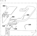
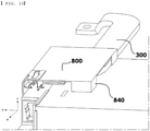
FIG. 8 is a perspective view of the battery pack according to the third preferred embodiment of the present invention before coupling, andFIG. 9 is a perspective view of the battery pack according to the third preferred embodiment of the present invention after coupling. - As can be seen from
FIGS. 8 and9 , thefastening device 830 according to the present invention may be coupled to acoupling portion 530 provided at the upper end of thebusbar assembly 500. As an example of the fastening device, as shown inFIG. 9 , aside fastening device 831 configured to fix theside cover 820 and an upperend fastening device 832 configured to fix theupper end cover 810 are fixed by a single fasteningdevice fixing portion 833, and theside fastening device 831 and the upperend fastening device 832 are coupled to thecoupling portion 530 provided at the upper end or the upper end and side surface of the busbar assembly so as to be fixed to the battery pack. - Although the
fastening device 830 may be located at one side surface of thethermal insulation cover 800 adjacent to the side edge thereof, it is preferable that the fastening device be provided at each of opposite side surfaces of thethermal insulation cover 800 in order to increase fixing force. - The
thermal insulation cover 800 may be coupled to a thermal insulation cover coupling portion provided at thebusbar assembly 500. In the case in which a busbar frame cover configured to fix thebusbar assembly 500 is provided, the thermal insulation cover coupling portion may be provided at the busbar frame cover. The thermal insulation cover coupling portion may be configured to have a shape corresponding to thefastening device 830. - Although the
thermal insulation cover 800 may have the above shape, the shape of the thermal insulation cover is not restricted as long as it is possible to protect the blockingstructure 400. - It is preferable that the
thermal insulation cover 800 be made of a thermal insulation material. - The reason for this is that it is necessary to block the transfer of heat due to fire breakout. In addition, the thermal insulation material may exhibit chemical resistance.
- Since the
thermal insulation cover 800 is made of a material that exhibits chemical resistance and thermal insulation, thethermal insulation cover 800 may primarily protect thesubmodule 100, and the blockingstructure 400 may secondarily protect the submodule, whereby it is possible to further protect thesubmodule 100. - Any material that can be used in a battery may be used as the thermal insulation material. In consideration of use of the battery pack, however, a material that has predetermined strength and generates no toxic substance is preferably used.
- As an example of the material, a compound including silicon may be used. Examples of the compound including silicon may include mica and ceramics. In addition, nylon or polyethylene terephthalate, which is a heat-resistant polymer, may be coated so as not to react with a chemical material in order to be used as the material for the
thermal insulation cover 800. - In the third preferred embodiment of the present invention, the
thermal insulation cover 800 ofFIG. 8 has a shape coupled so as to wrap the upper end and the side portion of thesubmodule 100. - Although the
fastening device 830 of thethermal insulation cover 800 may have a separate thermal insulation cover coupling portion, a space of thecoupling portion 530 for coupling of the busbar assembly provided at the coupling portion of thebusbar assembly 500 may be used. - The
fastening device 830 may be coupled to a space provided in a recessed portion of thecoupling portion 530, or may be coupled in a form inserted therein, in order to fix thethermal insulation cover 800. -
FIG. 10 is a view showing a modification of the third preferred embodiment of the present invention. - The modification of the third preferred embodiment of the present invention may have a shape in which the
thermal insulation cover 800 covers the entirety of theconnection busbar 300 provided at the upper part of thesubmodule 100 or may have a shape in which the thermal insulation cover covers only a portion of theconnection busbar 300. As described above, fire tends to spread while returning to an ignition point thereof when fire breaks out. For this reason, the thermal insulation cover may cover the entirety of theconnection busbar 300 in order to protect theconnection busbar 300 and to prevent spread of fire. - Also, in order to prevent spread of fire due to fire back, the
thermal insulation cover 800 according to the present invention may further include arear cover 840 provided parallel to theside cover 820, the rear cover being configured to protect theconnection busbar 300 and the rear surface of the blockingstructure 400. Therear cover 840 may be configured to have a shape that protects a portion that is not protected by theconnection busbar 300, as shown inFIG. 10 , or may have a long plate shape configured to protect theconnection busbar 300. In addition, therear cover 840 according to the present invention may have a structure configured to also protect a side surface portion of the blocking structure adjacent to the rear surface thereof, as shown inFIG. 10 . This structure is a structure prepared for the case in which some of fire is separated from the main current of fire and returns back. - Resistance values between a terminal portion and a mono frame in Example (2) to which the blocking structure according to the second embodiment of the present invention and the thermal insulation cover are applied and Comparative Example (26) in which only the thermal insulation cover is provided without the blocking structure according to the present invention are shown in the graph of
FIG. 11 . Model JH4 submodules sold by LG Chem were used as submodules, and mica was used as the material for the blocking structure according to the present invention and the thermal insulation cover. - A submodule of Example (2) and a submodule of Comparative Example (26) were disposed at opposite side surfaces of a trigger submodule (#33), and fire was set to the trigger submodule (#33).
FIG. 12 is a schematic view showing the dispositions of submodules for resistance measurement in the battery pack according to the second preferred embodiment of the present invention and Comparative Example. At this time, resistance values between the terminal unit and the submodule indicated by part 1 andpart 2 inFIG. 12 were measured as the resistance values. As shown inFIG. 11 , it can be seen that Example (2) of the submodule according to the present invention was not affected by fire, and therefore a resistance value of 5.E+03 Ω or more was maintained, whereas the submodule according to Comparative Example was affected a predetermined time (560 seconds) after fire broke out in an adjacent module, whereby the resistance of the submodule converged upon 0. In the case in which the blocking structure according to the present invention is provided, therefore, it can be seen that a predetermined resistance value, i.e. 3000 Ω or more, is maintained, whereby electrical conduction due to fire breakout does not occur and thus fire transfer due to overcurrent does not occur. - In the present invention, a connector or a fuse may be provided between the modules in order to prevent fire transfer due to overcurrent.
- The present invention may provide a device using any one of the battery packs described above as an energy source.
- The device may be any one selected from the group consisting of a mobile phone, a tablet computer, a laptop computer, a power tool, a wearable electronic device, an electric vehicle, a hybrid electric vehicle, a plug-in hybrid electric vehicle, and an energy storage system.
- Although the specific details of the present invention have been described in detail, those skilled in the art will appreciate that the detailed description thereof discloses only preferred embodiments of the present invention and thus does not limit the scope of the present invention. Accordingly, those skilled in the art will appreciate that various changes and modifications are possible, without departing from the category and the technical idea of the present invention, and it will be obvious that such changes and modifications fall within the scope of the appended claims.
-
- 10, 100:
- Submodules
- 11:
- Cartridge
- 12:
- Connection busbar receiving portion
- 20:
- Terminal unit
- 30, 300:
- Connection busbars
- 40:
- Bolt cover
- 400:
- Blocking structure
- 410:
- Upper structure
- 420:
- Terminal protecting portion
- 430:
- Side structure
- 440:
- Pollutant permeation preventing portion
- 450:
- Fixing portion
- 460:
- Connection busbar receiving portion
- 50, 500:
- Busbar assemblies
- 510:
- Busbar
- 520:
- Busbar frame
- 530:
- Coupling portion
- 600:
- Pack case
- 700:
- Side protecting portion
- 800:
- Thermal insulation cover
- 810:
- Upper end cover
- 820:
- Side cover
- 830:
- Fastening device
- 831:
- Side fastening device
- 832:
- Upper end fastening device
- 833:
- Fastening device fixing portion
- 840:
- Rear cover
- A battery pack according to the present invention includes a blocking structure configured to wrap a terminal unit, a busbar assembly, and a connection busbar of a submodule, whereby it is possible to protect an exposed region of the submodule while preventing movement of current from a connection region between the terminal unit and the connection busbar to a different region, and therefore it is possible to prevent continuous damage to submodules due to an adjacent submodule.
- The blocking structure is made of a material that exhibits chemical resistance and thermal insulation, whereby it is possible to prevent the terminal unit and the connection busbar from being polluted by a pollutant generated as the result of damage to an adjacent submodule. In addition, when fire breaks out in an adjacent submodule, it is possible to immediately prevent spread of fire using a thermal insulation material and to prevent heat to a predetermined extent, whereby it is possible to protect the submodule. As a result, it is possible to secure a time necessary to operate a fire extinguishing system in the battery pack or to warn a user, whereby it is possible to prevent further damage to the battery pack.
- In addition, it is possible to improve overall safety of a battery through a simple construction, such as the provision of a pollutant permeation preventing portion at the side surface portion of the blocking structure or the provision of a thermal insulation cover in addition to the blocking structure.
Claims (15)
- A battery pack comprising:two or more submodules, each of the two or more submodules having a plurality of unit cells, each of the plurality of unit cells comprising an electrode assembly and an electrode lead protruding from the electrode assembly;a pack case configured to receive the submodules;a busbar assembly comprising a busbar configured to electrically connect the electrode leads of the submodules to each other and a busbar frame connected to the busbar;a connection busbar configured to connect the submodules to each other;a terminal unit comprising a cluster of the electrode leads electrically connected to each other via the busbar, the terminal unit being connected to the connection busbar; anda blocking structure configured to wrap the terminal unit, the busbar assembly, and an upper end and a side surface of the connection busbar at a portion thereof connected to the terminal unit.
- The battery pack according to claim 1, wherein the blocking structure comprises an insulation material that exhibits chemical resistance and thermal insulation.
- The battery pack according to claim 3, wherein the insulation material comprises silicate.
- The battery pack according to claim 3, wherein the insulation material comprises mica or ceramics.
- The battery pack according to claim 1, wherein the blocking structure comprises:an upper structure configured to have a shape corresponding to the busbar assembly, the upper structure being located at an upper end of the busbar assembly;a terminal protecting portion protruding from the upper structure so as to have a shape corresponding to the terminal unit and the connection busbar;a side structure configured to further protect a different submodule facing portion of the busbar frame; anda pollutant permeation preventing portion located at a lower part of the upper structure, the pollutant permeation preventing portion being configured to protect opposite side surfaces of the terminal unit and opposite side surfaces of the connection busbar.
- The battery pack according to claim 5, wherein the pollutant permeation preventing portion is coupled to a space between the busbar and the terminal unit and the connection busbar connected thereto.
- The battery pack according to claim 1, wherein the blocking structure further comprises a thermal insulation cover configured to protect the blocking structure.
- The battery pack according to claim 7, wherein the thermal insulation cover comprises:an upper end cover provided at an upper part of the battery pack at which the busbar assembly and the blocking structure are located; anda side cover provided at a different submodule facing portion of the busbar assembly.
- The battery pack according to claim 7, wherein the thermal insulation cover comprises a thermal insulation material.
- The battery pack according to claim 9, wherein the thermal insulation material comprises silicate.
- The battery pack according to claim 10, wherein the thermal insulation material comprises mica or ceramics.
- The battery pack according to claim 8, wherein the thermal insulation cover is configured to cover the entirety of the connection busbar.
- The battery pack according to claim 8, wherein the thermal insulation cover further comprises a rear cover provided parallel to the side cover, the rear cover being configured to protect the connection busbar and a rear surface of the blocking structure.
- A device using the battery pack according to any one of claims 1 to 13 as an energy source.
- The device according to claim 14, wherein the device is any one selected from a group consisting of a mobile phone, a tablet computer, a laptop computer, a power tool, a wearable electronic device, an electric vehicle, a hybrid electric vehicle, a plug-in hybrid electric vehicle, and an energy storage system.
Applications Claiming Priority (2)
| Application Number | Priority Date | Filing Date | Title |
|---|---|---|---|
| KR1020200001345A KR102784314B1 (en) | 2020-01-06 | 2020-01-06 | Battery pack with improved safety and secondary battery including the same |
| PCT/KR2021/000060 WO2021141345A1 (en) | 2020-01-06 | 2021-01-05 | Battery pack having improved safety |
Publications (3)
| Publication Number | Publication Date |
|---|---|
| EP3972046A1 true EP3972046A1 (en) | 2022-03-23 |
| EP3972046A4 EP3972046A4 (en) | 2024-01-17 |
| EP3972046B1 EP3972046B1 (en) | 2026-04-08 |
Family
ID=76788832
Family Applications (1)
| Application Number | Title | Priority Date | Filing Date |
|---|---|---|---|
| EP21738120.1A Active EP3972046B1 (en) | 2020-01-06 | 2021-01-05 | Battery pack with improved safety |
Country Status (6)
| Country | Link |
|---|---|
| US (1) | US20220376323A1 (en) |
| EP (1) | EP3972046B1 (en) |
| JP (1) | JP7217073B2 (en) |
| KR (1) | KR102784314B1 (en) |
| CN (1) | CN113853710B (en) |
| WO (1) | WO2021141345A1 (en) |
Cited By (2)
| Publication number | Priority date | Publication date | Assignee | Title |
|---|---|---|---|---|
| EP4407782A4 (en) * | 2022-12-07 | 2024-08-14 | Eve Power Co., Ltd. | PROTECTIVE COVER, BATTERY DISCONNECTOR UNIT (BDU) HOUSING, BDU AND BATTERY PACK HOUSING |
| EP4636926A4 (en) * | 2022-12-22 | 2026-04-29 | Lg Energy Solution Ltd | DELAYED HEAT RELEASE BATTERY MODULE AND BATTERY PACK |
Families Citing this family (13)
| Publication number | Priority date | Publication date | Assignee | Title |
|---|---|---|---|---|
| DE102021110103A1 (en) | 2021-04-21 | 2022-10-27 | Dr. Ing. H.C. F. Porsche Aktiengesellschaft | Electrically operated or partially electrically operated vehicle comprising a high-voltage battery with a terminal compartment cover |
| KR102743553B1 (en) * | 2021-07-30 | 2024-12-16 | 컨템포러리 엠퍼렉스 테크놀로지 (홍콩) 리미티드 | Batteries, electrical equipment, battery manufacturing method and manufacturing equipment |
| US12609410B2 (en) | 2021-09-23 | 2026-04-21 | Lg Energy Solution, Ltd. | High heat-resistant connector, and battery module, battery pack, and vehicle including the same |
| JP7717952B2 (en) * | 2021-12-23 | 2025-08-04 | エルジー エナジー ソリューション リミテッド | Safety-enhanced battery module |
| KR102460160B1 (en) | 2022-03-31 | 2022-10-31 | (주)코리아하이테크 | Battery module having double-sided adhesive tape for reducing temperature and pressure caused by thermal runaway function |
| KR20230173887A (en) | 2022-06-20 | 2023-12-27 | 한국단자공업 주식회사 | Cap device for power connecting portion |
| KR20240058550A (en) * | 2022-10-26 | 2024-05-03 | 주식회사 엘지에너지솔루션 | Fireproof busbar cap and battery pack hanving the same |
| CN119404374A (en) * | 2022-11-30 | 2025-02-07 | 株式会社Lg新能源 | Battery module, battery pack and vehicle including the battery module |
| WO2024167124A1 (en) * | 2023-02-09 | 2024-08-15 | 주식회사 엘지에너지솔루션 | Battery module, and battery pack and vehicle including same |
| KR20240134669A (en) * | 2023-03-02 | 2024-09-10 | 주식회사 엘지에너지솔루션 | Battery module having blocking unit of flame exhaust and battery pack including the same |
| KR20240176243A (en) * | 2023-06-15 | 2024-12-24 | 주식회사 엘지에너지솔루션 | Battery module and battery pack including the same |
| KR20240177975A (en) * | 2023-06-21 | 2024-12-30 | 주식회사 엘지에너지솔루션 | Busbar assembly and battery pack including the same |
| JP7831455B2 (en) * | 2023-10-04 | 2026-03-17 | トヨタ自動車株式会社 | Energy storage device |
Family Cites Families (44)
| Publication number | Priority date | Publication date | Assignee | Title |
|---|---|---|---|---|
| DE3340425C2 (en) * | 1983-11-09 | 1987-04-02 | Brown, Boveri & Cie Ag, 6800 Mannheim | High-temperature storage battery based on alkali metal and chalcogen |
| TW460078U (en) * | 2000-03-21 | 2001-10-11 | Shie Kuen Chai | Safety device structure improvement of bus |
| JP5127154B2 (en) * | 2005-05-23 | 2013-01-23 | パナソニック株式会社 | Battery module |
| JP5408440B2 (en) * | 2010-01-18 | 2014-02-05 | 三菱自動車工業株式会社 | Battery case for vehicle |
| US20120115016A1 (en) | 2010-11-04 | 2012-05-10 | Myung-Chul Kim | Battery module |
| CN202076334U (en) * | 2011-05-27 | 2011-12-14 | 肇庆理士电源技术有限公司 | Lead row protective hood for storage battery |
| US9812680B2 (en) * | 2012-08-30 | 2017-11-07 | Apple Inc. | Low Z-fold battery seal |
| KR101440890B1 (en) * | 2013-01-29 | 2014-09-18 | 삼성에스디아이 주식회사 | Battery Pack |
| JP6130733B2 (en) * | 2013-05-27 | 2017-05-17 | 矢崎総業株式会社 | Busbar module |
| JP2015057759A (en) * | 2013-08-09 | 2015-03-26 | 住友電気工業株式会社 | Battery module, battery module unit and battery pack |
| KR102221801B1 (en) * | 2014-02-04 | 2021-03-02 | 삼성에스디아이 주식회사 | Busbar module |
| JP6252313B2 (en) * | 2014-03-31 | 2017-12-27 | 株式会社Gsユアサ | Power storage device |
| EP3170228B1 (en) * | 2014-07-16 | 2019-05-01 | Siemens Aktiengesellschaft | Subsea electrical connector component and method of manufacturing thereof |
| JP6724298B2 (en) * | 2014-07-31 | 2020-07-15 | 株式会社Gsユアサ | Power supply module |
| CN204441356U (en) * | 2015-03-05 | 2015-07-01 | 艾诺斯(重庆)华达电源系统有限公司 | A kind of analysing valve control type lead-acid accumulator battery cabling on cable rack structure |
| KR102449864B1 (en) * | 2015-09-04 | 2022-09-30 | 현대모비스 주식회사 | Connection device for battery module assembly |
| JP2017130338A (en) * | 2016-01-20 | 2017-07-27 | 住友電装株式会社 | Connection structure for battery cell |
| KR102034208B1 (en) | 2016-03-03 | 2019-10-18 | 주식회사 엘지화학 | Battery module, battery pack the battery module and vehicle comprising the battery pack |
| KR102285283B1 (en) * | 2016-05-11 | 2021-08-03 | 에스케이이노베이션 주식회사 | Submodule and battery module comprising the submodule |
| KR102119153B1 (en) * | 2016-07-21 | 2020-06-04 | 삼성에스디아이 주식회사 | Battery module |
| JP6699464B2 (en) * | 2016-09-05 | 2020-05-27 | 株式会社オートネットワーク技術研究所 | Connection module |
| KR102585708B1 (en) | 2016-11-24 | 2023-10-05 | 주식회사 엘지에너지솔루션 | Battery Pack having terminal with improved sealing structure and terminal cover |
| JP6878200B2 (en) * | 2017-08-09 | 2021-05-26 | 株式会社オートネットワーク技術研究所 | Bus bar module |
| US10615396B2 (en) * | 2017-09-08 | 2020-04-07 | Molex, Llc | Battery connection module |
| US11670805B2 (en) * | 2017-10-31 | 2023-06-06 | Snap Inc. | Nested PCM battery pack |
| KR102412941B1 (en) | 2018-01-19 | 2022-06-23 | 주식회사 엘지에너지솔루션 | Terminal cover and battery pack comprising the same |
| KR102383975B1 (en) * | 2018-02-06 | 2022-04-08 | 주식회사 엘지에너지솔루션 | Busbar device of battery, structure for fastening the busbar using the same, and battery pack having the same |
| KR102382386B1 (en) * | 2018-02-09 | 2022-04-01 | 주식회사 엘지에너지솔루션 | Bus Bar Having Current Interruption Part and Battery Module Having the Same |
| KR102150679B1 (en) | 2018-03-13 | 2020-09-01 | 주식회사 엘지화학 | Battery module, battery pack comprising the battery module and vehicle comprising the battery pack |
| WO2019232917A1 (en) * | 2018-06-05 | 2019-12-12 | Xu Yangxin | Curved light-concentrating reflector and processing system thereof, and light-concentrating reflector set and manufacturing method thereof |
| KR102372348B1 (en) | 2018-06-08 | 2022-03-07 | 주식회사 엘지에너지솔루션 | Battery module with improved cooling structure |
| DE102018114764B4 (en) * | 2018-06-20 | 2020-02-20 | Lisa Dräxlmaier GmbH | PLUG-IN MODULE CONNECTOR, CONNECTING SYSTEM AND METHOD FOR ELECTRICALLY CONDUCTING CONNECTING AT LEAST TWO BATTERY MODULES |
| KR102068326B1 (en) | 2018-06-27 | 2020-01-20 | 한국원자력의학원 | Radiation therapy apparatus for animals |
| CN209056530U (en) * | 2018-09-28 | 2019-07-02 | 宁德时代新能源科技股份有限公司 | Terminal protection cover and battery module |
| CN209217036U (en) * | 2018-10-09 | 2019-08-06 | 伟巴斯特车顶供暖系统(上海)有限公司 | Typical modular architecture, battery pack and vehicle based on cylindrical battery |
| CN208819951U (en) * | 2018-10-17 | 2019-05-03 | 宁德时代新能源科技股份有限公司 | Battery module and its protection component |
| KR102698844B1 (en) * | 2018-12-04 | 2024-08-23 | 주식회사 엘지에너지솔루션 | Battery pack |
| KR102416919B1 (en) * | 2019-02-26 | 2022-07-04 | 주식회사 엘지에너지솔루션 | Battery module |
| CN209822775U (en) * | 2019-06-03 | 2019-12-20 | 宁德时代新能源科技股份有限公司 | Terminal protection device and battery module |
| KR102754507B1 (en) * | 2019-10-18 | 2025-01-13 | 주식회사 엘지에너지솔루션 | Battery pack and device including the same |
| KR20220003729A (en) * | 2020-07-02 | 2022-01-11 | 주식회사 엘지에너지솔루션 | Battery module and battery pack including the same and manufacturing method of the same |
| KR20220051709A (en) * | 2020-10-19 | 2022-04-26 | 주식회사 엘지에너지솔루션 | Battery module and battery pack including the same |
| KR102941254B1 (en) * | 2020-11-04 | 2026-03-18 | 주식회사 엘지에너지솔루션 | Battery module and battery pack including the same |
| KR20220075946A (en) * | 2020-11-30 | 2022-06-08 | 주식회사 엘지에너지솔루션 | Battery module and battery pack including the same |
-
2020
- 2020-01-06 KR KR1020200001345A patent/KR102784314B1/en active Active
-
2021
- 2021-01-05 CN CN202180003450.4A patent/CN113853710B/en active Active
- 2021-01-05 EP EP21738120.1A patent/EP3972046B1/en active Active
- 2021-01-05 JP JP2021570215A patent/JP7217073B2/en active Active
- 2021-01-05 US US17/626,158 patent/US20220376323A1/en active Pending
- 2021-01-05 WO PCT/KR2021/000060 patent/WO2021141345A1/en not_active Ceased
Cited By (2)
| Publication number | Priority date | Publication date | Assignee | Title |
|---|---|---|---|---|
| EP4407782A4 (en) * | 2022-12-07 | 2024-08-14 | Eve Power Co., Ltd. | PROTECTIVE COVER, BATTERY DISCONNECTOR UNIT (BDU) HOUSING, BDU AND BATTERY PACK HOUSING |
| EP4636926A4 (en) * | 2022-12-22 | 2026-04-29 | Lg Energy Solution Ltd | DELAYED HEAT RELEASE BATTERY MODULE AND BATTERY PACK |
Also Published As
| Publication number | Publication date |
|---|---|
| KR20210088170A (en) | 2021-07-14 |
| EP3972046A4 (en) | 2024-01-17 |
| CN113853710A (en) | 2021-12-28 |
| WO2021141345A1 (en) | 2021-07-15 |
| CN113853710B (en) | 2023-05-30 |
| JP2022536041A (en) | 2022-08-12 |
| JP7217073B2 (en) | 2023-02-02 |
| US20220376323A1 (en) | 2022-11-24 |
| KR102784314B1 (en) | 2025-03-21 |
| EP3972046B1 (en) | 2026-04-08 |
Similar Documents
| Publication | Publication Date | Title |
|---|---|---|
| EP3972046B1 (en) | Battery pack with improved safety | |
| EP3907818B1 (en) | Battery pack having movable busbar assembly and secondary battery including the same | |
| EP4191750B1 (en) | Battery pack with improved cooling performance and device comprising same | |
| EP4131584B1 (en) | Battery module including thermal insulation member | |
| JP2024506457A (en) | Pouch-type battery cells with improved safety and battery modules containing the same | |
| EP4531192A1 (en) | Bus bar assembly and battery pack comprising same | |
| KR20230168499A (en) | Battery module | |
| KR101487152B1 (en) | Unit Module Assembly and Battery Module Comprising The Same | |
| EP4531193A1 (en) | Bus bar assembly and battery pack comprising same | |
| EP4535547A1 (en) | Busbar assembly and battery pack including same | |
| EP4131617B1 (en) | Battery module and battery pack including same | |
| CN114556688B (en) | Battery pack and device including the battery pack | |
| EP4597734A1 (en) | Busbar assembly and battery pack including same | |
| EP4604303A1 (en) | Busbar assembly and battery pack including same | |
| EP4661202A1 (en) | Busbar assembly and battery pack including same | |
| EP4614700A1 (en) | Busbar assembly and battery pack including same | |
| EP4531196A1 (en) | Busbar assembly and battery pack including same | |
| US20260031456A1 (en) | Battery pack having excellent impact resistance | |
| EP4243194A1 (en) | Pouch-type battery cell with improved thermal stability | |
| EP4485671A1 (en) | Bus bar assembly and battery pack comprising same | |
| KR20250147220A (en) | Battery module and battery pack and vehicle including the same | |
| JP2026502377A (en) | Battery module, battery pack including same, and automobile | |
| JP2025520164A (en) | Battery module, battery pack including said battery module, and automobile | |
| KR20260027589A (en) | Battery module and battery pack and vehicle including the same | |
| CN118202514A (en) | Battery module, battery pack and vehicle including the battery module |
Legal Events
| Date | Code | Title | Description |
|---|---|---|---|
| STAA | Information on the status of an ep patent application or granted ep patent |
Free format text: STATUS: THE INTERNATIONAL PUBLICATION HAS BEEN MADE |
|
| PUAI | Public reference made under article 153(3) epc to a published international application that has entered the european phase |
Free format text: ORIGINAL CODE: 0009012 |
|
| STAA | Information on the status of an ep patent application or granted ep patent |
Free format text: STATUS: REQUEST FOR EXAMINATION WAS MADE |
|
| 17P | Request for examination filed |
Effective date: 20211216 |
|
| AK | Designated contracting states |
Kind code of ref document: A1 Designated state(s): AL AT BE BG CH CY CZ DE DK EE ES FI FR GB GR HR HU IE IS IT LI LT LU LV MC MK MT NL NO PL PT RO RS SE SI SK SM TR |
|
| RAP3 | Party data changed (applicant data changed or rights of an application transferred) |
Owner name: LG ENERGY SOLUTION, LTD. |
|
| DAV | Request for validation of the european patent (deleted) | ||
| DAX | Request for extension of the european patent (deleted) | ||
| A4 | Supplementary search report drawn up and despatched |
Effective date: 20231220 |
|
| RIC1 | Information provided on ipc code assigned before grant |
Ipc: H01R 4/30 20060101ALI20231214BHEP Ipc: H01M 50/503 20210101ALI20231214BHEP Ipc: H01M 50/258 20210101ALI20231214BHEP Ipc: H01M 10/658 20140101ALI20231214BHEP Ipc: H01M 50/20 20210101ALI20231214BHEP Ipc: H01R 13/52 20060101ALI20231214BHEP Ipc: H01M 50/502 20210101ALI20231214BHEP Ipc: H01M 50/24 20210101ALI20231214BHEP Ipc: H01M 50/572 20210101AFI20231214BHEP |
|
| GRAP | Despatch of communication of intention to grant a patent |
Free format text: ORIGINAL CODE: EPIDOSNIGR1 |
|
| STAA | Information on the status of an ep patent application or granted ep patent |
Free format text: STATUS: GRANT OF PATENT IS INTENDED |
|
| INTG | Intention to grant announced |
Effective date: 20251217 |
|
| P01 | Opt-out of the competence of the unified patent court (upc) registered |
Free format text: CASE NUMBER: UPC_APP_0000243_3972046/2026 Effective date: 20260106 |
|
| GRAS | Grant fee paid |
Free format text: ORIGINAL CODE: EPIDOSNIGR3 |
|
| GRAA | (expected) grant |
Free format text: ORIGINAL CODE: 0009210 |
|
| STAA | Information on the status of an ep patent application or granted ep patent |
Free format text: STATUS: THE PATENT HAS BEEN GRANTED |
|
| AK | Designated contracting states |
Kind code of ref document: B1 Designated state(s): AL AT BE BG CH CY CZ DE DK EE ES FI FR GB GR HR HU IE IS IT LI LT LU LV MC MK MT NL NO PL PT RO RS SE SI SK SM TR |
|
| REG | Reference to a national code |
Ref country code: CH Ref legal event code: F10 Free format text: ST27 STATUS EVENT CODE: U-0-0-F10-F00 (AS PROVIDED BY THE NATIONAL OFFICE) Effective date: 20260408 Ref country code: GB Ref legal event code: FG4D |
|
| REG | Reference to a national code |
Ref country code: DE Ref legal event code: R096 Ref document number: 602021051628 Country of ref document: DE |