EP3971933A1 - Overcurrent tripping device, and circuit breaker in which overcurrent tripping device is used - Google Patents
Overcurrent tripping device, and circuit breaker in which overcurrent tripping device is used Download PDFInfo
- Publication number
- EP3971933A1 EP3971933A1 EP20805181.3A EP20805181A EP3971933A1 EP 3971933 A1 EP3971933 A1 EP 3971933A1 EP 20805181 A EP20805181 A EP 20805181A EP 3971933 A1 EP3971933 A1 EP 3971933A1
- Authority
- EP
- European Patent Office
- Prior art keywords
- fixed
- core
- fixed core
- movable
- tripping device
- Prior art date
- Legal status (The legal status is an assumption and is not a legal conclusion. Google has not performed a legal analysis and makes no representation as to the accuracy of the status listed.)
- Granted
Links
Images




Classifications
-
- H—ELECTRICITY
- H01—ELECTRIC ELEMENTS
- H01H—ELECTRIC SWITCHES; RELAYS; SELECTORS; EMERGENCY PROTECTIVE DEVICES
- H01H71/00—Details of the protective switches or relays covered by groups H01H73/00 - H01H83/00
- H01H71/10—Operating or release mechanisms
- H01H71/12—Automatic release mechanisms with or without manual release
- H01H71/24—Electromagnetic mechanisms
- H01H71/2409—Electromagnetic mechanisms combined with an electromagnetic current limiting mechanism
-
- H—ELECTRICITY
- H01—ELECTRIC ELEMENTS
- H01H—ELECTRIC SWITCHES; RELAYS; SELECTORS; EMERGENCY PROTECTIVE DEVICES
- H01H71/00—Details of the protective switches or relays covered by groups H01H73/00 - H01H83/00
- H01H71/10—Operating or release mechanisms
- H01H71/12—Automatic release mechanisms with or without manual release
- H01H71/24—Electromagnetic mechanisms
- H01H71/2454—Electromagnetic mechanisms characterised by the magnetic circuit or active magnetic elements
-
- H—ELECTRICITY
- H01—ELECTRIC ELEMENTS
- H01H—ELECTRIC SWITCHES; RELAYS; SELECTORS; EMERGENCY PROTECTIVE DEVICES
- H01H71/00—Details of the protective switches or relays covered by groups H01H73/00 - H01H83/00
- H01H71/10—Operating or release mechanisms
- H01H71/12—Automatic release mechanisms with or without manual release
- H01H71/24—Electromagnetic mechanisms
- H01H71/2463—Electromagnetic mechanisms with plunger type armatures
-
- H—ELECTRICITY
- H01—ELECTRIC ELEMENTS
- H01H—ELECTRIC SWITCHES; RELAYS; SELECTORS; EMERGENCY PROTECTIVE DEVICES
- H01H50/00—Details of electromagnetic relays
- H01H50/16—Magnetic circuit arrangements
- H01H50/18—Movable parts of magnetic circuits, e.g. armature
- H01H50/20—Movable parts of magnetic circuits, e.g. armature movable inside coil and substantially lengthwise with respect to axis thereof; movable coaxially with respect to coil
- H01H50/22—Movable parts of magnetic circuits, e.g. armature movable inside coil and substantially lengthwise with respect to axis thereof; movable coaxially with respect to coil wherein the magnetic circuit is substantially closed
- H01H2050/225—Movable parts of magnetic circuits, e.g. armature movable inside coil and substantially lengthwise with respect to axis thereof; movable coaxially with respect to coil wherein the magnetic circuit is substantially closed with yoke and armature formed by identical stacked laminates, e.g. punched in one and the same tool
-
- H—ELECTRICITY
- H01—ELECTRIC ELEMENTS
- H01H—ELECTRIC SWITCHES; RELAYS; SELECTORS; EMERGENCY PROTECTIVE DEVICES
- H01H71/00—Details of the protective switches or relays covered by groups H01H73/00 - H01H83/00
- H01H71/10—Operating or release mechanisms
- H01H71/12—Automatic release mechanisms with or without manual release
- H01H71/24—Electromagnetic mechanisms
- H01H2071/249—Electromagnetic mechanisms with part of the magnetic circuit being in the normal current path in the circuit breaker, e.g. yoke, fixed contact and arc-runner are made out of one single conductive element
Definitions
- the present disclosure relates to an overcurrent tripping device and a circuit breaker using the same.
- An overcurrent tripping device is a device that is incorporated into a circuit breaker and that detects an overcurrent flowing through a main circuit of the circuit breaker and actuates a tripping mechanism of the circuit breaker in a closed state.
- a specific overcurrent tripping device includes, for example, an electromagnet for detecting a fault current flowing through the main circuit, an output shaft for transmitting a drive force outputted from the electromagnet, to the tripping mechanism of the circuit breaker, a return spring for setting a current scale value (current prescribed value to start tripping operation) of the tripping device, and a scale device for adjusting the current scale value by manipulating the compression amount of the return spring to change the spring load.
- the overcurrent tripping device As operation of the overcurrent tripping device, it is indicated that when an overcurrent flows through a conductor penetrating the center of the electromagnet, a magnetic flux is generated in the electromagnet, a movable core forming the electromagnet is attracted upward, and a shaft connected to the movable core moves upward to drive a retention latch to separate the holding force that brings the circuit breaker into a closed state, from a movable contact (see, for example, Patent Document 1). Due to this separation, the circuit breaker shifts to an opened state.
- Patent Document 1 European Patent Publication No. 2431992
- Patent Document 1 it is possible to detect an overcurrent flowing through the main circuit of the circuit breaker, and actuate the tripping mechanism of the circuit breaker in a closed state.
- the mechanism included in the overcurrent tripping device in order to actuate the tripping mechanism is provided outside the electromagnet, there is a problem that the size of the overcurrent tripping device is increased.
- the present disclosure has been made to solve the above problems, and an object of the present disclosure is to obtain an overcurrent tripping device that shortens a tripping operation time for a fault current and that has a reduced size, and a circuit breaker using the same.
- An overcurrent tripping device which detects an overcurrent flowing through a main circuit of a circuit breaker and actuates a tripping mechanism of the circuit breaker in a closed state
- the overcurrent tripping device including: a conductor connected to the main circuit; a fixed core surrounding the conductor along a magnetic field generated around the conductor by a current flowing through the conductor, the fixed core being partially open so as to obliquely cut the magnetic field; a movable core having a magnetic gap between the fixed core and the movable core at a position where the fixed core is open, the movable core being disposed such that the movable core is movable in a direction in which the magnetic gap is reduced by an electromagnetic force generated when an overcurrent flows through the conductor; a rod penetrating an inside of the fixed core through a location where the fixed core is open and a portion of the fixed core facing the location where the fixed core is open, the rod being linked to the tripping mechanism at an
- the fixed core has a gap perpendicular to a direction in which the conductor extends, and, in the gap, a plate-shaped fixed core guide provided with a groove along a direction in which the rod extends is fixed and the lever is disposed.
- the movable core has a gap perpendicular to the direction in which the conductor extends, and a plate-shaped movable core guide which is partially interposed in the groove and slides in the direction in which the rod extends is fixed in the gap.
- a tripping operation time for a fault current can be shortened, and size reduction can be achieved.
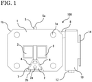
- FIG. 1 is a front view of an overcurrent tripping device 100
- FIG. 2 is a plan view of the overcurrent tripping device 100
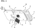
- FIG. 3 is a perspective view showing a part of the overcurrent tripping device 100
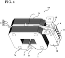
- FIG. 4 is a perspective view of the overcurrent tripping device 100.
- the overcurrent tripping device 100 is a device that is incorporated into a circuit breaker 200 described later and that moves a rod 5, which is fixed to a movable core 2, to actuate a tripping mechanism of the circuit breaker 200 in a closed state when an overcurrent flows through a main circuit of the circuit breaker 200.
- the configuration of the overcurrent tripping device 100 will be described.
- the overcurrent tripping device 100 includes: two conductors 3 which are connected to the main circuit (not shown) of the circuit breaker 200; a fixed core 1 which surrounds the conductors 3 along a magnetic field generated around the conductors 3 by a current flowing through the conductors 3 and which is partially open so as to obliquely cut the magnetic field; and the movable core 2 which has a magnetic gap 4 between the fixed core 1 and the movable core 2 at the position where the fixed core 1 is open and which is disposed such that the movable core 2 is movable in the direction in which the magnetic gap 4 is reduced, by an electromagnetic force generated when an overcurrent flows through the conductors 3.
- a magnetic circuit is formed by the fixed core 1 and the movable core 2.
- the fixed core 1 is a stacked core and includes stacked magnetic steel sheets 1b.
- Four fixed core pins 1a penetrate the magnetic steel sheets 1b in the direction in which the magnetic steel sheets 1b are stacked, to fix the magnetic steel sheets 1b together.
- the movable core 2 is also a stacked core and includes stacked magnetic steel sheets 2b, and two movable core pins 2a penetrate the magnetic steel sheets 2b in the direction in which the magnetic steel sheets 2b are stacked, to fix the magnetic steel sheets 2b together.
- the number of fixed core pins 1a and the number of movable core pins 2a are not limited to these numbers as long as the magnetic steel sheets 1b and the magnetic steel sheets 2b can be fixed.
- the fixed core 1 and the movable core 2 are preferably composed of stacked cores in order to suppress eddy currents, but the configurations thereof are not limited to the stacked configurations, and the fixed core 1 and the movable core 2 may each be composed of a block made of a ferromagnetic material such as iron-based materials.
- Each conductor 3 is made of, for example, copper.
- a main circuit current of the circuit breaker 200 flows through each conductor 3 to induce an electromagnetic force in the magnetic circuit.
- FIG. 1 shows an example in which the two conductors 3 are disposed and the rod 5 described later is moveable therebetween, but the present disclosure is not limited thereto, and the rod 5 may be disposed next to one conductor 3.
- the rod 5 is provided so as to extend in a bar shape, be movable in an axial direction thereof, and penetrate the inside of the fixed core 1 through the location where the fixed core 1 is open and a portion of the fixed core 1 facing the location where the fixed core 1 is open.
- the rod 5 is linked to a retention latch (not shown) connected to a tripping mechanism included in the circuit breaker 200, at an end projecting to the outside of the fixed core 1.
- the rod 5 is fitted with the movable core 2 to be fixed to the movable core 2.
- the rod 5 is made of a non-ferromagnetic material such as stainless steel, brass, and aluminum. This is because such a material does not affect the magnetic circuit included in the overcurrent tripping device 100.
- the fixed core 1 has gaps perpendicular to the direction in which the conductors 3 extend, and a plate-shaped fixed core guide 6 is fixed in each of the gaps.
- the fixed core guide 6 is interposed between the magnetic steel sheets 1b to be fixed therebetween.
- the fixed core guide 6 includes a plurality of plates and is stacked.
- the fixed core guide 6 includes two outer layers 6a and one inner layer 6b.
- the fixed core guide 6 is fixed by the fixed core pins 1a together with the magnetic steel sheets 1b.
- the rod 5 is disposed in a space provided between the right and left fixed core guides 6.
- a groove 6c is provided on each fixed core guide 6 along the direction in which the rod 5 extends.
- the side walls of the groove 6c are formed by the outer layers 6a, and the bottom of the groove 6c is formed by the inner layer 6b.
- the movable core 2 has a gap perpendicular to the direction in which the conductors 3 extend, and a plate-shaped movable core guide 7 which is partially interposed in the groove 6c and which slides in the direction in which the rod 5 extends is fixed in this gap.
- the direction in which the movable core 2 is movable is limited by the groove 6c.
- the movable core guide 7 is fixed by the movable core pins 2a together with the magnetic steel sheets 2b.
- the fixed core guides 6 and the movable core guide 7 are each preferably made of a non-ferromagnetic paramagnetic or diamagnetic material such as stainless steel, brass, and aluminum. This is because such a material does not affect the magnetic circuit included in the overcurrent tripping device 100.
- a lever 8 is connected at one end thereof to the rod 5 and connected at another end thereof to a spring 9 provided outside the fixed core 1.
- the lever 8 rotates about a fulcrum provided between the respective connection portions, and transmits the load force of the spring 9 to the movable core 2 via the rod 5.
- the lever 8 is provided inside the fixed core guide 6 in the direction in which the conductors 3 extend, in the gap of the fixed core 1, so as to be interposed between the two outer layers 6a.
- the lever 8 is fixed by the fixed core pin 1a, which penetrates the fixed core 1, together with the fixed core 1.
- the lever 8 rotates about the portion fixed by the fixed core pin 1a as a fulcrum.
- the lever 8 is fixed to the spring 9 by a spring seat 10.
- the lever 8 Since the lever 8 is provided so as to be interposed between the fixed core guides 6, scratching of the magnetic steel sheets 1b due to rotation of the lever 8 is suppressed.
- the lever 8 is made of a non-ferromagnetic material such as stainless steel, brass, and aluminum.
- the overcurrent tripping device 100 includes a stage 11 and a spring adjusting screw 12 outside the fixed core 1.
- the stage 11 is in contact with the spring 9 on one side, and is fitted with a screw hole provided such that the spring adjusting screw 12 disposed on the other side penetrates a center portion thereof.
- a side surface 11a of the stage 11 faces wall surfaces of the spring guide 13, so that rotation of the stage 11 about the axis of the screw hole is suppressed.
- the spring adjusting screw 12 is rotated, the stage 11 moves in the axial direction of the screw hole along the wall surfaces of the spring guide 13.
- the spring 9 expands and contracts, so that the load force of the spring 9 changes.
- the movable core 2 is biased by the spring 9 in the direction away from the fixed core 1, and the strength of the biasing of the movable core 2 changes as the stage 11 moves.
- the strength of the biasing of the movable core 2 is to set a current scale value (predetermined current prescribed value to start tripping operation) of the overcurrent tripping device 100, and it is made possible to set a plurality of current scale values by making the strength of the biasing of the movable core 2 adjustable.
- the initial load of the spring 9 is set so as to be equal to an electromagnetic drive force at the current scale value of the overcurrent tripping device 100.
- the spring guide 13 is provided so as to surround the spring 9 and the side surface of the stage 11.
- the spring guide 13 suppresses bending of the spring 9 in a direction other than the movement direction of the stage 11 and suppresses rotation of the stage 11.
- the spring guide 13 includes a scale 14 on the outside thereof. Since the scale 14 is provided, the position of the stage 11 can be quantitatively grasped. Since the position of the stage 11 is quantitatively grasped, the correlation between the position of the stage 11 and the current scale value can be recorded in advance, so that it is possible to change the current scale value on the basis of the recorded current scale value without causing a current to flow through the conductors 3 to operate the overcurrent tripping device 100.
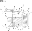
- FIG. 5 is a front partial cross-sectional view showing a state before tripping operation of the overcurrent tripping device 100 according to Embodiment 1
- FIG. 6 is a front partial cross-sectional view showing a state after tripping operation of the overcurrent tripping device 100.
- FIG. 5 and FIG. 6 are each a front partial cross-sectional view taken along an alternate long and short dash line A-A in FIG. 2 .
- a retention latch 51 is connected to the tripping mechanism (not shown) included in the circuit breaker 200, is in contact with another end 5a of the rod 5 on one side, and is rotatably fixed on the other side.
- the load force is given from the spring 9 to the movable core 2, and, as shown in FIG. 5 , the movable core 2 is placed at an initial position facing the fixed core 1 with the magnetic gap 4 therebetween.
- the movable core 2 moves from the initial position to a tripping position where the magnetic gap 4 is eliminated, as shown in FIG. 6 .
- An arrow shown in the fixed core 1 and the movable core 2 in the drawing indicates a magnetic circuit ⁇ , and a fault current I is shown in the conductors 3.
- the rod 5 moves together with the movable core 2, and the other end 5a rotates the retention latch 51 to release the latch.
- the tripping mechanism of the circuit breaker 200 connected to the retention latch 51 is actuated to bring the circuit breaker 200 into an opened state.
- each fixed core guide 6 includes a plurality of plates as shown in FIG. 3 is illustrated, but the present disclosure is not limited thereto.
- a fixed core guide 6 obtained by processing one plate, for example, by means of cutting may be adopted.
- the example in which the lever 8 is installed so as to be interposed between the two outer layers 6a as shown in FIG. 2 is illustrated, but the configuration for installing the lever 8 is not limited thereto.
- the lever 8 that has an increased thickness may be fixed so as to be interposed between the magnetic steel sheets 1b without providing the outer layers 6a at the location where the lever 8 is disposed.
- the thickness of the lever 8 can be increased to increase the rigidity of the lever 8 for transmitting the load force of the spring 9 to the movable core 2.
- the example in which the lever 8 is fixed by the fixed core pin 1a at the fulcrum about which the lever 8 is rotationally driven as shown in FIG. 5 is illustrated, but the configuration of the fulcrum for fixing the lever 8 is not limited thereto.
- a fulcrum for the lever 8 may be provided outside the fixed core 1 and the load force of the spring 9 may be transmitted to the movable core 2 using the principle of leverage.
- the rod 5 and the lever 8 involved in the operation of the tripping mechanism are provided inside the fixed core 1 in the overcurrent tripping device 100, the outer shape of the overcurrent tripping device 100 can be reduced and the size of the overcurrent tripping device 100 can be reduced.
- the rod 5 and the lever 8, which are movable parts are provided inside the fixed core 1, so that the sizes of the movable parts are reduced and the masses of the movable parts are decreased.
- the movement speeds of the movable parts when a fault current flows through the conductors 3 can be increased, and the tripping operation time for the fault current can be shortened.
- the thickness of the lever 8 is set to be equal to the thickness of the inner layer 6b, so that the size of the overcurrent tripping device 100 can be reduced.
- the groove 6c can be easily formed, and the manufacturing process for the overcurrent tripping device 100 can be simplified.
- the fixed core guides 6 and the movable core guide 7 are each formed from a paramagnetic or diamagnetic material, such a material does not affect the magnetic circuit included in the overcurrent tripping device 100, and the tripping operation time for a fault current can be shortened.
- the lever 8 in the case where the lever 8 is fixed by the fixed core pin 1a, the lever 8 can be fixed inside the fixed core 1 without adding any component, so that the weight of the overcurrent tripping device 100 can be reduced and the manufacturing process for the overcurrent tripping device 100 can be simplified.
- FIG. 8 is a front partial cross-sectional view of the overcurrent tripping device 100. An area shown in the cross-section is the same as in FIG. 5 .
- the position of the stage 11 which is provided in the overcurrent tripping device 100 shown in Embodiment 1 is different from that in Embodiment 1, and the stage 11 is provided on the side on which the rod 5 actuates the tripping mechanism.
- the direction in which the rod 5 actuates the tripping mechanism is shown by an arrow in FIG. 8 .
- the movable core 2 is provided so as to face the fixed core 1 on the side on which the rod 5 actuates the tripping mechanism. Therefore, the rod 5 penetrates the movable core 2 and is fixed to the movable core 2.
- the lever 8 is fixed by the fixed core pin 1a provided at the lower right of the fixed core 1.
- the stage 11 is disposed on the side on which the rod 5 actuates the tripping mechanism.
- the spring 9 generates a load force in the direction in which the rod 5 actuates the tripping mechanism, and transmits the load force to the lever 8. Similar to Embodiment 1, it is possible to change the current scale value by moving the stage 11 using a spring adjusting screw (not shown).
- the position of the stage 11 is on the side on which the tripping mechanism is actuated, and the position where the operator operates the spring adjusting screw is different from that in Embodiment 1.
- the number of choices of locations where the overcurrent tripping device 100 can be installed inside a circuit breaker can be increased.
- FIG. 9 is a front cross-sectional view showing a schematic configuration of the circuit breaker 200 using the overcurrent tripping device 100.
- the overcurrent tripping device 100 shown in Embodiment 1 or Embodiment 2 is incorporated into the circuit breaker 200, and the overcurrent tripping device 100 actuates the tripping mechanism of the circuit breaker 200 in a closed state.
- FIG. 8 shows the circuit breaker 200 inserted into a fixation framework 70.
- an upper conductor 53 and a lower conductor 54 are arranged under an arc-extinguishing chamber 52 in which an arc-extinguishing space is formed when a current flows.
- a fixed-side main contact 55 is connected to the upper conductor 53.
- the lower conductor 54 is connected to a movable conductor 57 via a flexible conductor 56, and a movable-side main contact 58 is provided at a position facing the fixed-side main contact 55, at an end of the movable conductor 57.
- the movable conductor 57 rotates about a rotation shaft 59.
- An opening operation is performed by an opening spring 60, and a closing operation is performed by an actuator 61.
- the overcurrent tripping device 100 is provided at a certain location on the lower conductor 54.
- the lower conductor 54 is connected to the conductors 3 of the overcurrent tripping device 100, and a main circuit current flows through the conductors 3.
- the overcurrent tripping device 100 is engaged with a latch 64 via a latch driving link 63.
- the latch driving link 63 shown by a broken line in FIG. 8 corresponds to a part for transmitting movement of the rod 5 of the overcurrent tripping device 100 described above with reference to FIG. 5 , to the retention latch 51, and on the basis of this operation, the latch 64 is driven.
- the overcurrent tripping device 100 provided on the lower conductor 54 detects an overcurrent and performs operation, and the operation is transmitted to the latch 64 via the latch driving link 63. Then, the latch 64 rotates about a latch shaft 65 in the clockwise direction, whereby engagement with the movable conductor 57 is released and the movable conductor 57 rotates about the rotation shaft 59 in the clockwise direction, thereby performing an opening operation.
- the fixed-side main contact 55 and the movable-side main contact 58 are housed inside the arc-extinguishing chamber 52.
- a fixed-side arc contact element 66 and a movable-side arc contact element 67 are disposed, and an arc is generated upon interruption.
- the fixed-side arc contact element 66 and the movable-side arc contact element 67 are opened after the fixed-side main contact 55 and the movable-side main contact 58 are opened.
- a fixed-side arc horn 68 and a movable-side arc horn 69 are disposed for transferring the generated arc and leading the arc upward in the arc-extinguishing chamber 52.
- the configuration of the circuit breaker 200 described with reference to FIG. 9 is merely an example, and is not limited thereto.
- the configuration of the circuit breaker 200 may be any configuration in which a current flowing through the main circuit of the circuit breaker 200 is detected by the overcurrent tripping device 100, and the engagement between the movable conductor 57 and the latch 64 is released by operation of the overcurrent tripping device 100 to bring the circuit breaker 200 into an opened state.
- the overcurrent tripping device 100 shown in Embodiment 1 or Embodiment 2 is incorporated into the circuit breaker 200, the movement speeds of the movable parts of the overcurrent tripping device 100 when a fault current flows through the lower conductor 54 can be increased, and the tripping operation time of the circuit breaker 200 for the fault current can be shortened.
- the size of the overcurrent tripping device 100 is reduced, a space in which the overcurrent tripping device 100 is installed in the circuit breaker 200 can be reduced, so that the size of the circuit breaker 200 can be reduced.
Landscapes
- Physics & Mathematics (AREA)
- Electromagnetism (AREA)
- Breakers (AREA)
Abstract
Description
- The present disclosure relates to an overcurrent tripping device and a circuit breaker using the same.
- An overcurrent tripping device is a device that is incorporated into a circuit breaker and that detects an overcurrent flowing through a main circuit of the circuit breaker and actuates a tripping mechanism of the circuit breaker in a closed state. A specific overcurrent tripping device includes, for example, an electromagnet for detecting a fault current flowing through the main circuit, an output shaft for transmitting a drive force outputted from the electromagnet, to the tripping mechanism of the circuit breaker, a return spring for setting a current scale value (current prescribed value to start tripping operation) of the tripping device, and a scale device for adjusting the current scale value by manipulating the compression amount of the return spring to change the spring load. As operation of the overcurrent tripping device, it is indicated that when an overcurrent flows through a conductor penetrating the center of the electromagnet, a magnetic flux is generated in the electromagnet, a movable core forming the electromagnet is attracted upward, and a shaft connected to the movable core moves upward to drive a retention latch to separate the holding force that brings the circuit breaker into a closed state, from a movable contact (see, for example, Patent Document 1). Due to this separation, the circuit breaker shifts to an opened state.
- Moreover, in the case where a fault occurs on an electric circuit including a circuit breaker and an overcurrent flows through the electric circuit, in order to reduce damage due to the overcurrent, it is effective to shorten, as much as possible, a time taken until completion of tripping operation from the time when the overcurrent occurs. In order to shorten the time taken until completion of tripping operation, in an overcurrent tripping device, a tripping drive force due to the overcurrent needs to greatly exceed a drive force at a current scale value, which can be achieved by reducing magnetic saturation of the electromagnet included in the overcurrent tripping device. Since the fault current of the circuit breaker increases transitionally within an extremely short time, a magnetomotive force of the overcurrent tripping device also increases transitionally during occurrence of the fault current, but when the electromagnet included in the overcurrent tripping device is magnetically saturated, the amount of increase in the tripping drive force reduces. Therefore, in order to shorten the tripping operation time, a core structure in which magnetic saturation is less likely to occur by the fault current may be adopted.
- Patent Document 1:
European Patent Publication No. 2431992 - In
Patent Document 1 above, it is possible to detect an overcurrent flowing through the main circuit of the circuit breaker, and actuate the tripping mechanism of the circuit breaker in a closed state. However, since the mechanism included in the overcurrent tripping device in order to actuate the tripping mechanism is provided outside the electromagnet, there is a problem that the size of the overcurrent tripping device is increased. In addition, no study has been made to shorten the time until taken completion of tripping operation. In order to shorten the time, for example, in this configuration, magnetic saturation can be reduced by increasing the volume of the core, which is the electromagnet, but there is a problem that the outer shape and mass of the overcurrent tripping device increase when the size of the core is increased. - The present disclosure has been made to solve the above problems, and an object of the present disclosure is to obtain an overcurrent tripping device that shortens a tripping operation time for a fault current and that has a reduced size, and a circuit breaker using the same.
- An overcurrent tripping device according to the present disclosure is an overcurrent tripping device which detects an overcurrent flowing through a main circuit of a circuit breaker and actuates a tripping mechanism of the circuit breaker in a closed state, the overcurrent tripping device including: a conductor connected to the main circuit; a fixed core surrounding the conductor along a magnetic field generated around the conductor by a current flowing through the conductor, the fixed core being partially open so as to obliquely cut the magnetic field; a movable core having a magnetic gap between the fixed core and the movable core at a position where the fixed core is open, the movable core being disposed such that the movable core is movable in a direction in which the magnetic gap is reduced by an electromagnetic force generated when an overcurrent flows through the conductor; a rod penetrating an inside of the fixed core through a location where the fixed core is open and a portion of the fixed core facing the location where the fixed core is open, the rod being linked to the tripping mechanism at an end projecting to the outside of the fixed core, the rod being fixed to the movable core in a bar shape; and a lever connected at one end thereof to the rod, connected at another end thereof to a spring provided outside the fixed core, and configured to rotate about a fulcrum provided between respective connection portions and transmit a load force of the spring to the movable core. The fixed core has a gap perpendicular to a direction in which the conductor extends, and, in the gap, a plate-shaped fixed core guide provided with a groove along a direction in which the rod extends is fixed and the lever is disposed. The movable core has a gap perpendicular to the direction in which the conductor extends, and a plate-shaped movable core guide which is partially interposed in the groove and slides in the direction in which the rod extends is fixed in the gap.
- In the overcurrent tripping device according to the present disclosure and the circuit breaker using the same, a tripping operation time for a fault current can be shortened, and size reduction can be achieved.
-
- [
FIG. 1] FIG. 1 is a front view of an overcurrent tripping device according toEmbodiment 1. - [
FIG. 2] FIG. 2 is a plan view of the overcurrent tripping device according toEmbodiment 1. - [
FIG. 3] FIG. 3 is a perspective view showing a part of the overcurrent tripping device according toEmbodiment 1. - [
FIG. 4] FIG. 4 is a perspective view of the overcurrent tripping device according toEmbodiment 1. - [
FIG. 5] FIG. 5 is a front partial cross-sectional view showing a state before tripping operation of the overcurrent tripping device according toEmbodiment 1. - [
FIG. 6] FIG. 6 is a front partial cross-sectional view showing a state after tripping operation of the overcurrent tripping device according toEmbodiment 1. - [
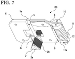
FIG. 7] FIG. 7 is a perspective view showing a part of the overcurrent tripping device according toEmbodiment 1. - [
FIG. 8] FIG. 8 is a front partial cross-sectional view of an overcurrent tripping device according toEmbodiment 2. - [
FIG. 9] FIG. 9 is a front cross-sectional view showing a schematic configuration of a circuit breaker according toEmbodiment 3 using the overcurrent tripping device. - Hereinafter, an overcurrent tripping device according to each of embodiments of the present disclosure and a circuit breaker using the same will be described with reference to the drawings. In the drawings, the same or corresponding members and parts are denoted by the same reference characters to give description.
-
FIG. 1 is a front view of anovercurrent tripping device 100,FIG. 2 is a plan view of theovercurrent tripping device 100,FIG. 3 is a perspective view showing a part of theovercurrent tripping device 100, andFIG. 4 is a perspective view of theovercurrent tripping device 100. Theovercurrent tripping device 100 is a device that is incorporated into acircuit breaker 200 described later and that moves arod 5, which is fixed to amovable core 2, to actuate a tripping mechanism of thecircuit breaker 200 in a closed state when an overcurrent flows through a main circuit of thecircuit breaker 200. Hereinafter, the configuration of theovercurrent tripping device 100 will be described. - The
overcurrent tripping device 100 includes: twoconductors 3 which are connected to the main circuit (not shown) of thecircuit breaker 200; afixed core 1 which surrounds theconductors 3 along a magnetic field generated around theconductors 3 by a current flowing through theconductors 3 and which is partially open so as to obliquely cut the magnetic field; and themovable core 2 which has amagnetic gap 4 between thefixed core 1 and themovable core 2 at the position where thefixed core 1 is open and which is disposed such that themovable core 2 is movable in the direction in which themagnetic gap 4 is reduced, by an electromagnetic force generated when an overcurrent flows through theconductors 3. A magnetic circuit is formed by thefixed core 1 and themovable core 2. The fixedcore 1 is a stacked core and includes stackedmagnetic steel sheets 1b. Fourfixed core pins 1a penetrate themagnetic steel sheets 1b in the direction in which themagnetic steel sheets 1b are stacked, to fix themagnetic steel sheets 1b together. Themovable core 2 is also a stacked core and includes stackedmagnetic steel sheets 2b, and twomovable core pins 2a penetrate themagnetic steel sheets 2b in the direction in which themagnetic steel sheets 2b are stacked, to fix themagnetic steel sheets 2b together. The number of fixedcore pins 1a and the number ofmovable core pins 2a are not limited to these numbers as long as themagnetic steel sheets 1b and themagnetic steel sheets 2b can be fixed. Thefixed core 1 and themovable core 2 are preferably composed of stacked cores in order to suppress eddy currents, but the configurations thereof are not limited to the stacked configurations, and thefixed core 1 and themovable core 2 may each be composed of a block made of a ferromagnetic material such as iron-based materials. Eachconductor 3 is made of, for example, copper. A main circuit current of thecircuit breaker 200 flows through eachconductor 3 to induce an electromagnetic force in the magnetic circuit.FIG. 1 shows an example in which the twoconductors 3 are disposed and therod 5 described later is moveable therebetween, but the present disclosure is not limited thereto, and therod 5 may be disposed next to oneconductor 3. - The
rod 5 is provided so as to extend in a bar shape, be movable in an axial direction thereof, and penetrate the inside of the fixedcore 1 through the location where thefixed core 1 is open and a portion of thefixed core 1 facing the location where thefixed core 1 is open. Therod 5 is linked to a retention latch (not shown) connected to a tripping mechanism included in thecircuit breaker 200, at an end projecting to the outside of the fixedcore 1. For example, therod 5 is fitted with themovable core 2 to be fixed to themovable core 2. Therod 5 is made of a non-ferromagnetic material such as stainless steel, brass, and aluminum. This is because such a material does not affect the magnetic circuit included in theovercurrent tripping device 100. - As shown in
FIG. 2 , thefixed core 1 has gaps perpendicular to the direction in which theconductors 3 extend, and a plate-shapedfixed core guide 6 is fixed in each of the gaps. Thefixed core guide 6 is interposed between themagnetic steel sheets 1b to be fixed therebetween. Thefixed core guide 6 includes a plurality of plates and is stacked. Thefixed core guide 6 includes twoouter layers 6a and oneinner layer 6b. Thefixed core guide 6 is fixed by thefixed core pins 1a together with themagnetic steel sheets 1b. Therod 5 is disposed in a space provided between the right and left fixedcore guides 6. As shown inFIG. 3 , agroove 6c is provided on eachfixed core guide 6 along the direction in which therod 5 extends. The side walls of thegroove 6c are formed by theouter layers 6a, and the bottom of thegroove 6c is formed by theinner layer 6b. - As shown in
FIG. 3 , themovable core 2 has a gap perpendicular to the direction in which theconductors 3 extend, and a plate-shapedmovable core guide 7 which is partially interposed in thegroove 6c and which slides in the direction in which therod 5 extends is fixed in this gap. The direction in which themovable core 2 is movable is limited by thegroove 6c. Themovable core guide 7 is fixed by the movable core pins 2a together with themagnetic steel sheets 2b. The fixed core guides 6 and themovable core guide 7 are each preferably made of a non-ferromagnetic paramagnetic or diamagnetic material such as stainless steel, brass, and aluminum. This is because such a material does not affect the magnetic circuit included in theovercurrent tripping device 100. - A
lever 8 is connected at one end thereof to therod 5 and connected at another end thereof to aspring 9 provided outside the fixedcore 1. Thelever 8 rotates about a fulcrum provided between the respective connection portions, and transmits the load force of thespring 9 to themovable core 2 via therod 5. Thelever 8 is provided inside the fixedcore guide 6 in the direction in which theconductors 3 extend, in the gap of the fixedcore 1, so as to be interposed between the twoouter layers 6a. Thelever 8 is fixed by the fixedcore pin 1a, which penetrates the fixedcore 1, together with the fixedcore 1. Thelever 8 rotates about the portion fixed by the fixedcore pin 1a as a fulcrum. Thelever 8 is fixed to thespring 9 by aspring seat 10. Since thelever 8 is provided so as to be interposed between the fixed core guides 6, scratching of themagnetic steel sheets 1b due to rotation of thelever 8 is suppressed. Thelever 8 is made of a non-ferromagnetic material such as stainless steel, brass, and aluminum. - In addition to the
spring 9, theovercurrent tripping device 100 includes astage 11 and aspring adjusting screw 12 outside the fixedcore 1. Thestage 11 is in contact with thespring 9 on one side, and is fitted with a screw hole provided such that thespring adjusting screw 12 disposed on the other side penetrates a center portion thereof. Inside aspring guide 13 shown inFIG. 4 , aside surface 11a of thestage 11 faces wall surfaces of thespring guide 13, so that rotation of thestage 11 about the axis of the screw hole is suppressed. When thespring adjusting screw 12 is rotated, thestage 11 moves in the axial direction of the screw hole along the wall surfaces of thespring guide 13. As thestage 11 moves, thespring 9 expands and contracts, so that the load force of thespring 9 changes. Themovable core 2 is biased by thespring 9 in the direction away from the fixedcore 1, and the strength of the biasing of themovable core 2 changes as thestage 11 moves. The strength of the biasing of themovable core 2 is to set a current scale value (predetermined current prescribed value to start tripping operation) of theovercurrent tripping device 100, and it is made possible to set a plurality of current scale values by making the strength of the biasing of themovable core 2 adjustable. The initial load of thespring 9 is set so as to be equal to an electromagnetic drive force at the current scale value of theovercurrent tripping device 100. - The
spring guide 13 is provided so as to surround thespring 9 and the side surface of thestage 11. Thespring guide 13 suppresses bending of thespring 9 in a direction other than the movement direction of thestage 11 and suppresses rotation of thestage 11. Thespring guide 13 includes ascale 14 on the outside thereof. Since thescale 14 is provided, the position of thestage 11 can be quantitatively grasped. Since the position of thestage 11 is quantitatively grasped, the correlation between the position of thestage 11 and the current scale value can be recorded in advance, so that it is possible to change the current scale value on the basis of the recorded current scale value without causing a current to flow through theconductors 3 to operate theovercurrent tripping device 100. - Next, tripping operation of the
overcurrent tripping device 100 will be described.FIG. 5 is a front partial cross-sectional view showing a state before tripping operation of theovercurrent tripping device 100 according toEmbodiment 1, andFIG. 6 is a front partial cross-sectional view showing a state after tripping operation of theovercurrent tripping device 100.FIG. 5 andFIG. 6 are each a front partial cross-sectional view taken along an alternate long and short dash line A-A inFIG. 2 . Aretention latch 51 is connected to the tripping mechanism (not shown) included in thecircuit breaker 200, is in contact with anotherend 5a of therod 5 on one side, and is rotatably fixed on the other side. Before tripping operation in which a fault current does not flow through theconductors 3, the load force is given from thespring 9 to themovable core 2, and, as shown inFIG. 5 , themovable core 2 is placed at an initial position facing the fixedcore 1 with themagnetic gap 4 therebetween. When a fault current flows through theconductors 3 and the electromagnetic drive force acting on themovable core 2 becomes larger than the load force of thespring 9, themovable core 2 moves from the initial position to a tripping position where themagnetic gap 4 is eliminated, as shown inFIG. 6 . An arrow shown in the fixedcore 1 and themovable core 2 in the drawing indicates a magnetic circuit Φ, and a fault current I is shown in theconductors 3. Therod 5 moves together with themovable core 2, and theother end 5a rotates theretention latch 51 to release the latch. The tripping mechanism of thecircuit breaker 200 connected to theretention latch 51 is actuated to bring thecircuit breaker 200 into an opened state. - In the present embodiment, the example in which each fixed
core guide 6 includes a plurality of plates as shown inFIG. 3 is illustrated, but the present disclosure is not limited thereto. As shown inFIG. 7 , a fixedcore guide 6 obtained by processing one plate, for example, by means of cutting may be adopted. - Moreover, in the present embodiment, the example in which the
lever 8 is installed so as to be interposed between the twoouter layers 6a as shown inFIG. 2 is illustrated, but the configuration for installing thelever 8 is not limited thereto. Thelever 8 that has an increased thickness may be fixed so as to be interposed between themagnetic steel sheets 1b without providing theouter layers 6a at the location where thelever 8 is disposed. The thickness of thelever 8 can be increased to increase the rigidity of thelever 8 for transmitting the load force of thespring 9 to themovable core 2. - Moreover, in the present embodiment, the example in which the
lever 8 is fixed by the fixedcore pin 1a at the fulcrum about which thelever 8 is rotationally driven as shown inFIG. 5 is illustrated, but the configuration of the fulcrum for fixing thelever 8 is not limited thereto. Instead of fixing thelever 8 by the fixedcore pin 1a, a fulcrum for thelever 8 may be provided outside the fixedcore 1 and the load force of thespring 9 may be transmitted to themovable core 2 using the principle of leverage. - As described above, since the
rod 5 and thelever 8 involved in the operation of the tripping mechanism are provided inside the fixedcore 1 in theovercurrent tripping device 100, the outer shape of theovercurrent tripping device 100 can be reduced and the size of theovercurrent tripping device 100 can be reduced. In addition, therod 5 and thelever 8, which are movable parts, are provided inside the fixedcore 1, so that the sizes of the movable parts are reduced and the masses of the movable parts are decreased. Thus, the movement speeds of the movable parts when a fault current flows through theconductors 3 can be increased, and the tripping operation time for the fault current can be shortened. Moreover, in the case where thelever 8 is provided so as to be interposed between the twoouter layers 6a, the thickness of thelever 8 is set to be equal to the thickness of theinner layer 6b, so that the size of theovercurrent tripping device 100 can be reduced. Moreover, in the case where each fixedcore guide 6 is stacked and provided to form thegroove 6c, thegroove 6c can be easily formed, and the manufacturing process for theovercurrent tripping device 100 can be simplified. Moreover, in the case where the fixed core guides 6 and themovable core guide 7 are each formed from a paramagnetic or diamagnetic material, such a material does not affect the magnetic circuit included in theovercurrent tripping device 100, and the tripping operation time for a fault current can be shortened. Moreover, in the case where thelever 8 is fixed by the fixedcore pin 1a, thelever 8 can be fixed inside the fixedcore 1 without adding any component, so that the weight of theovercurrent tripping device 100 can be reduced and the manufacturing process for theovercurrent tripping device 100 can be simplified. - An
overcurrent tripping device 100 according toEmbodiment 2 will be described.FIG. 8 is a front partial cross-sectional view of theovercurrent tripping device 100. An area shown in the cross-section is the same as inFIG. 5 . In theovercurrent tripping device 100 according toEmbodiment 2, the position of thestage 11 which is provided in theovercurrent tripping device 100 shown inEmbodiment 1 is different from that inEmbodiment 1, and thestage 11 is provided on the side on which therod 5 actuates the tripping mechanism. - The direction in which the
rod 5 actuates the tripping mechanism is shown by an arrow inFIG. 8 . Themovable core 2 is provided so as to face the fixedcore 1 on the side on which therod 5 actuates the tripping mechanism. Therefore, therod 5 penetrates themovable core 2 and is fixed to themovable core 2. Thelever 8 is fixed by the fixedcore pin 1a provided at the lower right of the fixedcore 1. Thus, thestage 11 is disposed on the side on which therod 5 actuates the tripping mechanism. In this configuration, thespring 9 generates a load force in the direction in which therod 5 actuates the tripping mechanism, and transmits the load force to thelever 8. Similar toEmbodiment 1, it is possible to change the current scale value by moving thestage 11 using a spring adjusting screw (not shown). - As described above, in the
overcurrent tripping device 100, the position of thestage 11 is on the side on which the tripping mechanism is actuated, and the position where the operator operates the spring adjusting screw is different from that inEmbodiment 1. Thus, the number of choices of locations where theovercurrent tripping device 100 can be installed inside a circuit breaker can be increased. - The
circuit breaker 200 according toEmbodiment 3 will be described.FIG. 9 is a front cross-sectional view showing a schematic configuration of thecircuit breaker 200 using theovercurrent tripping device 100. Theovercurrent tripping device 100 shown inEmbodiment 1 orEmbodiment 2 is incorporated into thecircuit breaker 200, and theovercurrent tripping device 100 actuates the tripping mechanism of thecircuit breaker 200 in a closed state.FIG. 8 shows thecircuit breaker 200 inserted into afixation framework 70. - In the
circuit breaker 200, anupper conductor 53 and alower conductor 54 are arranged under an arc-extinguishingchamber 52 in which an arc-extinguishing space is formed when a current flows. A fixed-sidemain contact 55 is connected to theupper conductor 53. Thelower conductor 54 is connected to amovable conductor 57 via aflexible conductor 56, and a movable-sidemain contact 58 is provided at a position facing the fixed-sidemain contact 55, at an end of themovable conductor 57. Themovable conductor 57 rotates about arotation shaft 59. An opening operation is performed by anopening spring 60, and a closing operation is performed by anactuator 61. When the fixed-sidemain contact 55 and the movable-sidemain contact 58 are brought into contact with each other, a current flows between theupper conductor 53 and thelower conductor 54 via themovable conductor 57 and theflexible conductor 56. - The
overcurrent tripping device 100 is provided at a certain location on thelower conductor 54. Thelower conductor 54 is connected to theconductors 3 of theovercurrent tripping device 100, and a main circuit current flows through theconductors 3. Theovercurrent tripping device 100 is engaged with alatch 64 via alatch driving link 63. Here, thelatch driving link 63 shown by a broken line inFIG. 8 corresponds to a part for transmitting movement of therod 5 of theovercurrent tripping device 100 described above with reference toFIG. 5 , to theretention latch 51, and on the basis of this operation, thelatch 64 is driven. - Next, operation when a fault current flows will be described. When a fault current flows, the
overcurrent tripping device 100 provided on thelower conductor 54 detects an overcurrent and performs operation, and the operation is transmitted to thelatch 64 via thelatch driving link 63. Then, thelatch 64 rotates about alatch shaft 65 in the clockwise direction, whereby engagement with themovable conductor 57 is released and themovable conductor 57 rotates about therotation shaft 59 in the clockwise direction, thereby performing an opening operation. - The fixed-side
main contact 55 and the movable-sidemain contact 58 are housed inside the arc-extinguishingchamber 52. Above the fixed-sidemain contact 55 and the movable-sidemain contact 58, a fixed-sidearc contact element 66 and a movable-sidearc contact element 67 are disposed, and an arc is generated upon interruption. In an opening operation, the fixed-sidearc contact element 66 and the movable-sidearc contact element 67 are opened after the fixed-sidemain contact 55 and the movable-sidemain contact 58 are opened. Thus, an arc is prevented from being generated at the fixed-sidemain contact 55 and the movable-sidemain contact 58, and erosion of the main contact part is prevented, whereby the main contact part is protected. Above the fixed-sidearc contact element 66 and the movable-sidearc contact element 67, a fixed-side arc horn 68 and a movable-side arc horn 69 are disposed for transferring the generated arc and leading the arc upward in the arc-extinguishingchamber 52. - The configuration of the
circuit breaker 200 described with reference toFIG. 9 is merely an example, and is not limited thereto. The configuration of thecircuit breaker 200 may be any configuration in which a current flowing through the main circuit of thecircuit breaker 200 is detected by theovercurrent tripping device 100, and the engagement between themovable conductor 57 and thelatch 64 is released by operation of theovercurrent tripping device 100 to bring thecircuit breaker 200 into an opened state. - As described above, since the
overcurrent tripping device 100 shown inEmbodiment 1 orEmbodiment 2 is incorporated into thecircuit breaker 200, the movement speeds of the movable parts of theovercurrent tripping device 100 when a fault current flows through thelower conductor 54 can be increased, and the tripping operation time of thecircuit breaker 200 for the fault current can be shortened. In addition, since the size of theovercurrent tripping device 100 is reduced, a space in which theovercurrent tripping device 100 is installed in thecircuit breaker 200 can be reduced, so that the size of thecircuit breaker 200 can be reduced. - Although the disclosure is described above in terms of various exemplary embodiments and implementations, it should be understood that the various features, aspects, and functionality described in one or more of the individual embodiments are not limited in their applicability to the particular embodiment with which they are described, but instead can be applied, alone or in various combinations to one or more of the embodiments of the disclosure.
- It is therefore understood that numerous modifications which have not been exemplified can be devised without departing from the scope of the present disclosure. For example, at least one of the constituent components may be modified, added, or eliminated. At least one of the constituent components mentioned in at least one of the preferred embodiments may be selected and combined with the constituent components mentioned in another preferred embodiment.
-
- 1
- fixed core
- 1a
- fixed core pin
- 1b
- magnetic steel sheet
- 2
- movable core
- 2a
- movable core pin
- 2b
- magnetic steel sheet
- 3
- conductor
- 4
- magnetic gap
- 5
- rod
- 5a
- other end
- 6
- fixed core guide
- 6a
- outer layer
- 6b
- inner layer
- 6c
- groove
- 7
- movable core guide
- 8
- lever
- 9
- spring
- 10
- spring seat
- 11
- stage
- 11a
- side surface
- 12
- spring adjusting screw
- 13
- spring guide
- 14
- scale
- 51
- retention latch
- 52
- arc-extinguishing chamber
- 53
- upper conductor
- 54
- lower conductor
- 55
- fixed-side main contact
- 56
- flexible conductor
- 57
- movable conductor
- 58
- movable-side main contact
- 59
- rotation shaft
- 60
- opening spring
- 61
- actuator
- 63
- latch driving link
- 64
- latch
- 65
- latch shaft
- 66
- fixed-side arc contact element
- 67
- movable-side arc contact element
- 68
- fixed-side arc horn
- 69
- movable-side arc horn
- 70
- fixation framework
- 100
- overcurrent tripping device
- 200
- circuit breaker
Claims (6)
- An overcurrent tripping device which detects an overcurrent flowing through a main circuit of a circuit breaker and actuates a tripping mechanism of the circuit breaker in a closed state, the overcurrent tripping device comprising:a conductor connected to the main circuit;a fixed core surrounding the conductor along a magnetic field generated around the conductor by a current flowing through the conductor, the fixed core being partially open so as to obliquely cut the magnetic field;a movable core having a magnetic gap between the fixed core and the movable core at a position where the fixed core is open, the movable core being disposed such that the movable core is movable in a direction in which the magnetic gap is reduced by an electromagnetic force generated when an overcurrent flows through the conductor;a rod penetrating an inside of the fixed core through a location where the fixed core is open and a portion of the fixed core facing the location where the fixed core is open, the rod being linked to the tripping mechanism at an end projecting to the outside of the fixed core, the rod being fixed to the movable core in a bar shape; anda lever connected at one end thereof to the rod, connected at another end thereof to a spring provided outside the fixed core, and configured to rotate about a fulcrum provided between respective connection portions and transmit a load force of the spring to the movable core, whereinthe fixed core has a gap perpendicular to a direction in which the conductor extends, and, in the gap, a plate-shaped fixed core guide provided with a groove along a direction in which the rod extends is fixed and the lever is disposed, andthe movable core has a gap perpendicular to the direction in which the conductor extends, and a plate-shaped movable core guide which is partially interposed in the groove and slides in the direction in which the rod extends is fixed in the gap.
- The overcurrent tripping device according to claim 1, wherein the lever is provided inside the fixed core guide in the direction in which the conductor extends.
- The overcurrent tripping device according to claim 1 or 2, whereinthe fixed core guide includes a plurality of plates and is stacked, anda side wall of the groove is formed by an outer layer of the fixed core guide, and a bottom of the groove is formed by an inner layer of the fixed core guide.
- The overcurrent tripping device according to any one of claims 1 to 3, wherein the lever is fixed by a fixed core pin penetrating the fixed core, together with the fixed core.
- The overcurrent tripping device according to any one of claims 1 to 4, wherein the fixed core guide and the movable core guide are each formed from a paramagnetic or diamagnetic material.
- A circuit breaker comprising:an arc-extinguishing chamber in which an arc-extinguishing space is formed;a fixed-side main contact located under the arc-extinguishing chamber;a movable-side main contact located so as to be contactable with and separable from the fixed-side main contact; andthe overcurrent tripping device according to any one of claims 1 to 5 which detects an overcurrent flowing between the fixed-side main contact and the movable-side main contact and drives the movable-side main contact in a tripping direction.
Applications Claiming Priority (2)
| Application Number | Priority Date | Filing Date | Title |
|---|---|---|---|
| JP2019092701 | 2019-05-16 | ||
| PCT/JP2020/018509 WO2020230684A1 (en) | 2019-05-16 | 2020-05-07 | Overcurrent tripping device, and circuit breaker in which overcurrent tripping device is used |
Publications (3)
| Publication Number | Publication Date |
|---|---|
| EP3971933A1 true EP3971933A1 (en) | 2022-03-23 |
| EP3971933A4 EP3971933A4 (en) | 2022-06-22 |
| EP3971933B1 EP3971933B1 (en) | 2023-04-12 |
Family
ID=73290208
Family Applications (1)
| Application Number | Title | Priority Date | Filing Date |
|---|---|---|---|
| EP20805181.3A Active EP3971933B1 (en) | 2019-05-16 | 2020-05-07 | Overcurrent tripping device, and circuit breaker in which overcurrent tripping device is used |
Country Status (3)
| Country | Link |
|---|---|
| EP (1) | EP3971933B1 (en) |
| JP (1) | JP7109664B2 (en) |
| WO (1) | WO2020230684A1 (en) |
Cited By (1)
| Publication number | Priority date | Publication date | Assignee | Title |
|---|---|---|---|---|
| EP4564394A1 (en) * | 2023-11-30 | 2025-06-04 | Abb Schweiz Ag | Core for circuit breaker mechanism and circuit breaker mechanism |
Families Citing this family (2)
| Publication number | Priority date | Publication date | Assignee | Title |
|---|---|---|---|---|
| WO2022130552A1 (en) * | 2020-12-17 | 2022-06-23 | 三菱電機株式会社 | Overcurrent trip device, and circuit breaker using same |
| CN113782353B (en) * | 2021-09-15 | 2022-07-12 | 福州大学 | A new type of CPS rotary electromagnetic operating mechanism and its working method |
Family Cites Families (7)
| Publication number | Priority date | Publication date | Assignee | Title |
|---|---|---|---|---|
| DE29723307U1 (en) * | 1997-04-11 | 1998-08-06 | AEG Niederspannungstechnik GmbH & Co KG, 24534 Neumünster | Fast overcurrent release for DC high-speed switches |
| DE19715114A1 (en) * | 1997-04-11 | 1998-10-22 | Aeg Niederspannungstech Gmbh | Overcurrent trigger for fast DC switch |
| EP2431992B1 (en) | 2010-09-20 | 2013-01-23 | Sécheron SA | Release mechanism for circuit interrupting device |
| US10453638B2 (en) * | 2015-06-19 | 2019-10-22 | Mitsubishi Electric Corporation | Overcurrent tripping device and circuit breaker employing same |
| WO2017183679A1 (en) * | 2016-04-22 | 2017-10-26 | 三菱電機株式会社 | Contactor device for circuit breaker and circuit breaker using same contactor device |
| CN111052288B (en) * | 2017-08-21 | 2022-02-08 | 三菱电机株式会社 | breaker |
| CN111033669B (en) * | 2017-08-21 | 2021-11-09 | 三菱电机株式会社 | Electromagnetic operating mechanism and circuit breaker |
-
2020
- 2020-05-07 JP JP2021519389A patent/JP7109664B2/en active Active
- 2020-05-07 WO PCT/JP2020/018509 patent/WO2020230684A1/en not_active Ceased
- 2020-05-07 EP EP20805181.3A patent/EP3971933B1/en active Active
Cited By (1)
| Publication number | Priority date | Publication date | Assignee | Title |
|---|---|---|---|---|
| EP4564394A1 (en) * | 2023-11-30 | 2025-06-04 | Abb Schweiz Ag | Core for circuit breaker mechanism and circuit breaker mechanism |
Also Published As
| Publication number | Publication date |
|---|---|
| JP7109664B2 (en) | 2022-07-29 |
| WO2020230684A1 (en) | 2020-11-19 |
| EP3971933A4 (en) | 2022-06-22 |
| EP3971933B1 (en) | 2023-04-12 |
| JPWO2020230684A1 (en) | 2021-11-18 |
Similar Documents
| Publication | Publication Date | Title |
|---|---|---|
| EP3971933B1 (en) | Overcurrent tripping device, and circuit breaker in which overcurrent tripping device is used | |
| US10453638B2 (en) | Overcurrent tripping device and circuit breaker employing same | |
| EP2871651B1 (en) | Circuit breaker | |
| CN102449720A (en) | Electromagnetic trip device | |
| KR20150028830A (en) | Electrical contact apparatus, assemblies, and methods of operation | |
| JP6072065B2 (en) | TRIP MECHANISM AND ELECTRICAL SWITCHING EQUIPMENT INCLUDING TRIP MEMBER PRESSED BY PRESSURE RESULTING FROM AN ARC IN AN ARC Chamber | |
| TW200805411A (en) | Breaker | |
| JP7399276B2 (en) | trip device | |
| JP5093081B2 (en) | Electromagnetic actuator | |
| JP4770640B2 (en) | Electromagnetic actuator | |
| US7482902B2 (en) | Linear magnetic drive | |
| KR101410780B1 (en) | Trip actuator of switch for electric power circuit | |
| HK40067800A (en) | Overcurrent tripping device, and circuit breaker in which overcurrent tripping device is used | |
| HK40067800B (en) | Overcurrent tripping device, and circuit breaker in which overcurrent tripping device is used | |
| CN101390180A (en) | Magnetostrictive electrical switching devices | |
| EP4266343B1 (en) | Overcurrent trip device, and circuit breaker using same | |
| JP5366599B2 (en) | Electromagnet and switchgear using the same | |
| JP2008204864A (en) | Switch | |
| CN101521130A (en) | Remote operation unit of breaker | |
| HK40096955A (en) | Overcurrent trip device, and circuit breaker using same | |
| JP2017220348A (en) | Circuit breaker | |
| EP3182437A2 (en) | Clapper armature with curved pole face | |
| JP2006294449A (en) | Switchgear and electromagnetic actuator | |
| KR20130001368U (en) | Instant trip mechanism for home circuit breaker | |
| JPS62272419A (en) | Tripping apparatus for circuit breaker |
Legal Events
| Date | Code | Title | Description |
|---|---|---|---|
| STAA | Information on the status of an ep patent application or granted ep patent |
Free format text: STATUS: THE INTERNATIONAL PUBLICATION HAS BEEN MADE |
|
| PUAI | Public reference made under article 153(3) epc to a published international application that has entered the european phase |
Free format text: ORIGINAL CODE: 0009012 |
|
| STAA | Information on the status of an ep patent application or granted ep patent |
Free format text: STATUS: REQUEST FOR EXAMINATION WAS MADE |
|
| 17P | Request for examination filed |
Effective date: 20210804 |
|
| AK | Designated contracting states |
Kind code of ref document: A1 Designated state(s): AL AT BE BG CH CY CZ DE DK EE ES FI FR GB GR HR HU IE IS IT LI LT LU LV MC MK MT NL NO PL PT RO RS SE SI SK SM TR |
|
| A4 | Supplementary search report drawn up and despatched |
Effective date: 20220520 |
|
| RIC1 | Information provided on ipc code assigned before grant |
Ipc: H01H 71/24 20060101AFI20220516BHEP |
|
| DAV | Request for validation of the european patent (deleted) | ||
| DAX | Request for extension of the european patent (deleted) | ||
| REG | Reference to a national code |
Ref country code: HK Ref legal event code: DE Ref document number: 40067800 Country of ref document: HK |
|
| GRAP | Despatch of communication of intention to grant a patent |
Free format text: ORIGINAL CODE: EPIDOSNIGR1 |
|
| STAA | Information on the status of an ep patent application or granted ep patent |
Free format text: STATUS: GRANT OF PATENT IS INTENDED |
|
| INTG | Intention to grant announced |
Effective date: 20221024 |
|
| GRAS | Grant fee paid |
Free format text: ORIGINAL CODE: EPIDOSNIGR3 |
|
| GRAA | (expected) grant |
Free format text: ORIGINAL CODE: 0009210 |
|
| STAA | Information on the status of an ep patent application or granted ep patent |
Free format text: STATUS: THE PATENT HAS BEEN GRANTED |
|
| AK | Designated contracting states |
Kind code of ref document: B1 Designated state(s): AL AT BE BG CH CY CZ DE DK EE ES FI FR GB GR HR HU IE IS IT LI LT LU LV MC MK MT NL NO PL PT RO RS SE SI SK SM TR |
|
| REG | Reference to a national code |
Ref country code: GB Ref legal event code: FG4D |
|
| REG | Reference to a national code |
Ref country code: CH Ref legal event code: EP |
|
| REG | Reference to a national code |
Ref country code: DE Ref legal event code: R096 Ref document number: 602020009744 Country of ref document: DE |
|
| REG | Reference to a national code |
Ref country code: IE Ref legal event code: FG4D |
|
| REG | Reference to a national code |
Ref country code: AT Ref legal event code: REF Ref document number: 1560254 Country of ref document: AT Kind code of ref document: T Effective date: 20230515 |
|
| P01 | Opt-out of the competence of the unified patent court (upc) registered |
Effective date: 20230424 |
|
| REG | Reference to a national code |
Ref country code: LT Ref legal event code: MG9D |
|
| REG | Reference to a national code |
Ref country code: NL Ref legal event code: MP Effective date: 20230412 |
|
| REG | Reference to a national code |
Ref country code: AT Ref legal event code: MK05 Ref document number: 1560254 Country of ref document: AT Kind code of ref document: T Effective date: 20230412 |
|
| PG25 | Lapsed in a contracting state [announced via postgrant information from national office to epo] |
Ref country code: NL Free format text: LAPSE BECAUSE OF FAILURE TO SUBMIT A TRANSLATION OF THE DESCRIPTION OR TO PAY THE FEE WITHIN THE PRESCRIBED TIME-LIMIT Effective date: 20230412 |
|
| PG25 | Lapsed in a contracting state [announced via postgrant information from national office to epo] |
Ref country code: SE Free format text: LAPSE BECAUSE OF FAILURE TO SUBMIT A TRANSLATION OF THE DESCRIPTION OR TO PAY THE FEE WITHIN THE PRESCRIBED TIME-LIMIT Effective date: 20230412 Ref country code: PT Free format text: LAPSE BECAUSE OF FAILURE TO SUBMIT A TRANSLATION OF THE DESCRIPTION OR TO PAY THE FEE WITHIN THE PRESCRIBED TIME-LIMIT Effective date: 20230814 Ref country code: NO Free format text: LAPSE BECAUSE OF FAILURE TO SUBMIT A TRANSLATION OF THE DESCRIPTION OR TO PAY THE FEE WITHIN THE PRESCRIBED TIME-LIMIT Effective date: 20230712 Ref country code: ES Free format text: LAPSE BECAUSE OF FAILURE TO SUBMIT A TRANSLATION OF THE DESCRIPTION OR TO PAY THE FEE WITHIN THE PRESCRIBED TIME-LIMIT Effective date: 20230412 Ref country code: AT Free format text: LAPSE BECAUSE OF FAILURE TO SUBMIT A TRANSLATION OF THE DESCRIPTION OR TO PAY THE FEE WITHIN THE PRESCRIBED TIME-LIMIT Effective date: 20230412 |
|
| PG25 | Lapsed in a contracting state [announced via postgrant information from national office to epo] |
Ref country code: RS Free format text: LAPSE BECAUSE OF FAILURE TO SUBMIT A TRANSLATION OF THE DESCRIPTION OR TO PAY THE FEE WITHIN THE PRESCRIBED TIME-LIMIT Effective date: 20230412 Ref country code: PL Free format text: LAPSE BECAUSE OF FAILURE TO SUBMIT A TRANSLATION OF THE DESCRIPTION OR TO PAY THE FEE WITHIN THE PRESCRIBED TIME-LIMIT Effective date: 20230412 Ref country code: LV Free format text: LAPSE BECAUSE OF FAILURE TO SUBMIT A TRANSLATION OF THE DESCRIPTION OR TO PAY THE FEE WITHIN THE PRESCRIBED TIME-LIMIT Effective date: 20230412 Ref country code: LT Free format text: LAPSE BECAUSE OF FAILURE TO SUBMIT A TRANSLATION OF THE DESCRIPTION OR TO PAY THE FEE WITHIN THE PRESCRIBED TIME-LIMIT Effective date: 20230412 Ref country code: IS Free format text: LAPSE BECAUSE OF FAILURE TO SUBMIT A TRANSLATION OF THE DESCRIPTION OR TO PAY THE FEE WITHIN THE PRESCRIBED TIME-LIMIT Effective date: 20230812 Ref country code: HR Free format text: LAPSE BECAUSE OF FAILURE TO SUBMIT A TRANSLATION OF THE DESCRIPTION OR TO PAY THE FEE WITHIN THE PRESCRIBED TIME-LIMIT Effective date: 20230412 Ref country code: GR Free format text: LAPSE BECAUSE OF FAILURE TO SUBMIT A TRANSLATION OF THE DESCRIPTION OR TO PAY THE FEE WITHIN THE PRESCRIBED TIME-LIMIT Effective date: 20230713 Ref country code: AL Free format text: LAPSE BECAUSE OF FAILURE TO SUBMIT A TRANSLATION OF THE DESCRIPTION OR TO PAY THE FEE WITHIN THE PRESCRIBED TIME-LIMIT Effective date: 20230412 |
|
| PG25 | Lapsed in a contracting state [announced via postgrant information from national office to epo] |
Ref country code: FI Free format text: LAPSE BECAUSE OF FAILURE TO SUBMIT A TRANSLATION OF THE DESCRIPTION OR TO PAY THE FEE WITHIN THE PRESCRIBED TIME-LIMIT Effective date: 20230412 |
|
| REG | Reference to a national code |
Ref country code: DE Ref legal event code: R097 Ref document number: 602020009744 Country of ref document: DE |
|
| PG25 | Lapsed in a contracting state [announced via postgrant information from national office to epo] |
Ref country code: SK Free format text: LAPSE BECAUSE OF FAILURE TO SUBMIT A TRANSLATION OF THE DESCRIPTION OR TO PAY THE FEE WITHIN THE PRESCRIBED TIME-LIMIT Effective date: 20230412 |
|
| PG25 | Lapsed in a contracting state [announced via postgrant information from national office to epo] |
Ref country code: MC Free format text: LAPSE BECAUSE OF FAILURE TO SUBMIT A TRANSLATION OF THE DESCRIPTION OR TO PAY THE FEE WITHIN THE PRESCRIBED TIME-LIMIT Effective date: 20230412 |
|
| REG | Reference to a national code |
Ref country code: BE Ref legal event code: MM Effective date: 20230531 |
|
| PG25 | Lapsed in a contracting state [announced via postgrant information from national office to epo] |
Ref country code: SM Free format text: LAPSE BECAUSE OF FAILURE TO SUBMIT A TRANSLATION OF THE DESCRIPTION OR TO PAY THE FEE WITHIN THE PRESCRIBED TIME-LIMIT Effective date: 20230412 Ref country code: SK Free format text: LAPSE BECAUSE OF FAILURE TO SUBMIT A TRANSLATION OF THE DESCRIPTION OR TO PAY THE FEE WITHIN THE PRESCRIBED TIME-LIMIT Effective date: 20230412 Ref country code: RO Free format text: LAPSE BECAUSE OF FAILURE TO SUBMIT A TRANSLATION OF THE DESCRIPTION OR TO PAY THE FEE WITHIN THE PRESCRIBED TIME-LIMIT Effective date: 20230412 Ref country code: MC Free format text: LAPSE BECAUSE OF FAILURE TO SUBMIT A TRANSLATION OF THE DESCRIPTION OR TO PAY THE FEE WITHIN THE PRESCRIBED TIME-LIMIT Effective date: 20230412 Ref country code: LU Free format text: LAPSE BECAUSE OF NON-PAYMENT OF DUE FEES Effective date: 20230507 Ref country code: EE Free format text: LAPSE BECAUSE OF FAILURE TO SUBMIT A TRANSLATION OF THE DESCRIPTION OR TO PAY THE FEE WITHIN THE PRESCRIBED TIME-LIMIT Effective date: 20230412 Ref country code: DK Free format text: LAPSE BECAUSE OF FAILURE TO SUBMIT A TRANSLATION OF THE DESCRIPTION OR TO PAY THE FEE WITHIN THE PRESCRIBED TIME-LIMIT Effective date: 20230412 Ref country code: CZ Free format text: LAPSE BECAUSE OF FAILURE TO SUBMIT A TRANSLATION OF THE DESCRIPTION OR TO PAY THE FEE WITHIN THE PRESCRIBED TIME-LIMIT Effective date: 20230412 |
|
| PLBE | No opposition filed within time limit |
Free format text: ORIGINAL CODE: 0009261 |
|
| STAA | Information on the status of an ep patent application or granted ep patent |
Free format text: STATUS: NO OPPOSITION FILED WITHIN TIME LIMIT |
|
| REG | Reference to a national code |
Ref country code: IE Ref legal event code: MM4A |
|
| 26N | No opposition filed |
Effective date: 20240115 |
|
| PG25 | Lapsed in a contracting state [announced via postgrant information from national office to epo] |
Ref country code: IE Free format text: LAPSE BECAUSE OF NON-PAYMENT OF DUE FEES Effective date: 20230507 |
|
| PG25 | Lapsed in a contracting state [announced via postgrant information from national office to epo] |
Ref country code: IE Free format text: LAPSE BECAUSE OF NON-PAYMENT OF DUE FEES Effective date: 20230507 |
|
| PG25 | Lapsed in a contracting state [announced via postgrant information from national office to epo] |
Ref country code: SI Free format text: LAPSE BECAUSE OF FAILURE TO SUBMIT A TRANSLATION OF THE DESCRIPTION OR TO PAY THE FEE WITHIN THE PRESCRIBED TIME-LIMIT Effective date: 20230412 |
|
| PG25 | Lapsed in a contracting state [announced via postgrant information from national office to epo] |
Ref country code: SI Free format text: LAPSE BECAUSE OF FAILURE TO SUBMIT A TRANSLATION OF THE DESCRIPTION OR TO PAY THE FEE WITHIN THE PRESCRIBED TIME-LIMIT Effective date: 20230412 Ref country code: IT Free format text: LAPSE BECAUSE OF FAILURE TO SUBMIT A TRANSLATION OF THE DESCRIPTION OR TO PAY THE FEE WITHIN THE PRESCRIBED TIME-LIMIT Effective date: 20230412 Ref country code: FR Free format text: LAPSE BECAUSE OF NON-PAYMENT OF DUE FEES Effective date: 20230612 Ref country code: BE Free format text: LAPSE BECAUSE OF NON-PAYMENT OF DUE FEES Effective date: 20230531 |
|
| PG25 | Lapsed in a contracting state [announced via postgrant information from national office to epo] |
Ref country code: BG Free format text: LAPSE BECAUSE OF FAILURE TO SUBMIT A TRANSLATION OF THE DESCRIPTION OR TO PAY THE FEE WITHIN THE PRESCRIBED TIME-LIMIT Effective date: 20230412 |
|
| PG25 | Lapsed in a contracting state [announced via postgrant information from national office to epo] |
Ref country code: BG Free format text: LAPSE BECAUSE OF FAILURE TO SUBMIT A TRANSLATION OF THE DESCRIPTION OR TO PAY THE FEE WITHIN THE PRESCRIBED TIME-LIMIT Effective date: 20230412 |
|
| PGFP | Annual fee paid to national office [announced via postgrant information from national office to epo] |
Ref country code: DE Payment date: 20250402 Year of fee payment: 6 |
|
| PGFP | Annual fee paid to national office [announced via postgrant information from national office to epo] |
Ref country code: CH Payment date: 20250601 Year of fee payment: 6 |
|
| PG25 | Lapsed in a contracting state [announced via postgrant information from national office to epo] |
Ref country code: CY Free format text: LAPSE BECAUSE OF FAILURE TO SUBMIT A TRANSLATION OF THE DESCRIPTION OR TO PAY THE FEE WITHIN THE PRESCRIBED TIME-LIMIT; INVALID AB INITIO Effective date: 20200507 |
|
| PG25 | Lapsed in a contracting state [announced via postgrant information from national office to epo] |
Ref country code: HU Free format text: LAPSE BECAUSE OF FAILURE TO SUBMIT A TRANSLATION OF THE DESCRIPTION OR TO PAY THE FEE WITHIN THE PRESCRIBED TIME-LIMIT; INVALID AB INITIO Effective date: 20200507 |
|
| PG25 | Lapsed in a contracting state [announced via postgrant information from national office to epo] |
Ref country code: TR Free format text: LAPSE BECAUSE OF FAILURE TO SUBMIT A TRANSLATION OF THE DESCRIPTION OR TO PAY THE FEE WITHIN THE PRESCRIBED TIME-LIMIT Effective date: 20230412 |
|
| PGFP | Annual fee paid to national office [announced via postgrant information from national office to epo] |
Ref country code: GB Payment date: 20260323 Year of fee payment: 7 |