EP3971927A1 - Contactor control - Google Patents
Contactor control Download PDFInfo
- Publication number
- EP3971927A1 EP3971927A1 EP20196398.0A EP20196398A EP3971927A1 EP 3971927 A1 EP3971927 A1 EP 3971927A1 EP 20196398 A EP20196398 A EP 20196398A EP 3971927 A1 EP3971927 A1 EP 3971927A1
- Authority
- EP
- European Patent Office
- Prior art keywords
- contactor
- contacts
- current
- pair
- closed position
- Prior art date
- Legal status (The legal status is an assumption and is not a legal conclusion. Google has not performed a legal analysis and makes no representation as to the accuracy of the status listed.)
- Granted
Links
Images

Classifications
-
- H—ELECTRICITY
- H01—ELECTRIC ELEMENTS
- H01H—ELECTRIC SWITCHES; RELAYS; SELECTORS; EMERGENCY PROTECTIVE DEVICES
- H01H47/00—Circuit arrangements not adapted to a particular application of the relay and designed to obtain desired operating characteristics or to provide energising current
- H01H47/22—Circuit arrangements not adapted to a particular application of the relay and designed to obtain desired operating characteristics or to provide energising current for supplying energising current for relay coil
-
- H—ELECTRICITY
- H01—ELECTRIC ELEMENTS
- H01H—ELECTRIC SWITCHES; RELAYS; SELECTORS; EMERGENCY PROTECTIVE DEVICES
- H01H1/00—Contacts
- H01H1/0015—Means for testing or for inspecting contacts, e.g. wear indicator
-
- H—ELECTRICITY
- H01—ELECTRIC ELEMENTS
- H01H—ELECTRIC SWITCHES; RELAYS; SELECTORS; EMERGENCY PROTECTIVE DEVICES
- H01H47/00—Circuit arrangements not adapted to a particular application of the relay and designed to obtain desired operating characteristics or to provide energising current
- H01H47/002—Monitoring or fail-safe circuits
-
- G—PHYSICS
- G01—MEASURING; TESTING
- G01R—MEASURING ELECTRIC VARIABLES; MEASURING MAGNETIC VARIABLES
- G01R31/00—Arrangements for testing electric properties; Arrangements for locating electric faults; Arrangements for electrical testing characterised by what is being tested not provided for elsewhere
- G01R31/327—Testing of circuit interrupters, switches or circuit-breakers
- G01R31/3277—Testing of circuit interrupters, switches or circuit-breakers of low voltage devices, e.g. domestic or industrial devices, such as motor protections, relays, rotation switches
- G01R31/3278—Testing of circuit interrupters, switches or circuit-breakers of low voltage devices, e.g. domestic or industrial devices, such as motor protections, relays, rotation switches of relays, solenoids or reed switches
-
- H—ELECTRICITY
- H01—ELECTRIC ELEMENTS
- H01H—ELECTRIC SWITCHES; RELAYS; SELECTORS; EMERGENCY PROTECTIVE DEVICES
- H01H1/00—Contacts
- H01H1/50—Means for increasing contact pressure, preventing vibration of contacts, holding contacts together after engagement, or biasing contacts to the open position
- H01H2001/506—Fail safe contacts, i.e. the contacts being kept in a safe position, usually in an open circuit position, at end of life time of switch
-
- H—ELECTRICITY
- H01—ELECTRIC ELEMENTS
- H01H—ELECTRIC SWITCHES; RELAYS; SELECTORS; EMERGENCY PROTECTIVE DEVICES
- H01H47/00—Circuit arrangements not adapted to a particular application of the relay and designed to obtain desired operating characteristics or to provide energising current
- H01H47/002—Monitoring or fail-safe circuits
- H01H2047/006—Detecting unwanted movement of contacts and applying pulses to coil for restoring to normal status
-
- H—ELECTRICITY
- H01—ELECTRIC ELEMENTS
- H01H—ELECTRIC SWITCHES; RELAYS; SELECTORS; EMERGENCY PROTECTIVE DEVICES
- H01H71/00—Details of the protective switches or relays covered by groups H01H73/00 - H01H83/00
- H01H71/04—Means for indicating condition of the switching device
- H01H2071/044—Monitoring, detection or measuring systems to establish the end of life of the switching device, can also contain other on-line monitoring systems, e.g. for detecting mechanical failures
Definitions
- the present disclosure relates to a method of controlling a mechanical contactor.
- a mechanical contactor is a switching device normally intended for performing a high number of switching operations during normal load and overload conditions.
- the IEC product standard defines a mechanical contactor as a mechanical switching device having only one position of rest, operated otherwise than by hand, capable of making, carrying and breaking currents under normal circuit conditions including operating overload conditions.
- a traditional application is to start, run and stop electrical 3-phase AC-motors just by applying and removing voltage to the circuit. It means that the contactor shall be able to make the inrush current and carry the starting current during a limited time, it shall also be able to carry the normal current during continuous operation and finally break the current when the motor shall be stopped. In some cases, the contactor may also need to break the starting current that can be significantly higher than the normal current and therefore the breaking capacity should be high enough for these cases.
- a short circuit fault is normally not handled by the contactor, but by a Short Circuit Protection Device (SCPD) like for instance fuses or circuit breakers.
- SCPD Short Circuit Protection Device
- a short circuit is a critical situation for a contactor since the current can be very high, even if the time period with very high current is short, the separation forces on the contacts can be high and the energy dissipated in the device can also be high.
- the coordination between the SCPD and the contactor can be difficult and is often an issue.
- the large current flowing through the contacts of the contactor induce Lorenz forces which may force the contacts to separate, resulting in an electric arc between the contacts.
- the arc itself is a plasma but on the contact surfaces there will be melted contact material when the arc is burning. This happens during a normal current breaking procedure as well as during a contact separation caused by a short circuit.
- the contacts are brought completely apart, and the arc is extinguished by an extinction system, the current is broken by the contactor itself and the contacts stay in fully open position and cool down.
- the contacts may be pressed apart unintentionally by the Lorenz forces, creating an arc with melted material on the contact surfaces.
- the separation force disappears and the contacts may again be pressed together.
- the melted material on the surfaces may then weld together when the contacts cool down and the contactor may no longer be opened since the contacts are stuck in a shorted position. This prevents the contactor from being reused after a short circuit fault.
- a method of controlling a mechanical contactor comprising at least one pair of contacts for conducting a mains current when the contactor is in a closed position, and an electromagnet arranged to close the contactor, and maintain the contactor in the closed position, by forcing the pair of contacts towards each other when a control current runs through a coil of the electromagnet.
- the method comprises, while the contactor is in the closed position, obtaining an indication of unintentional separation of the contacts, and in response to the obtained indication, opening the contactor and maintaining the contactor in an open position by turning off the control current.
- a computer program product comprising computer-executable components for causing a controller to perform an embodiment of the method of the present disclosure when the computer-executable components are run on processing circuitry comprised in the controller.
- a controller for a mechanical contactor comprises processing circuitry, and storage storing instructions executable by said processing circuitry whereby said controller is operative to, while the contactor is in the closed position, obtain an indication of unintentional separation of contacts of a pair of contacts of the contactor, for conducting a mains current when the contactor is in the closed position, and to, in response to the obtained indication, open the contactor and maintaining the contactor in an open position by turning off a control current in a coil of an electromagnet arranged to close the contactor, and maintain the contactor in the closed position, by forcing the pair of contacts towards each other when the control current runs through said coil.
- a mechanical contactor comprising an embodiment of the controller of the present disclosure, the pair of contacts for conducting the mains current when the contactor is in the closed position, and the electromagnet arranged to close the contactor and maintain the contactor in the closed position by forcing the pair of contacts towards each other when the control current runs through the coil of the electromagnet.
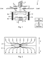
- Figure 1 illustrates a contactor 1 arranged to make, carry and break a main current Im, e.g. between a line and a load.
- the contactor comprises at least one pair of contacts 2, which make the main current Im when brought in contact with each other (closing the contactor, i.e. bringing the contactor from an open position to a closed position), carry the main current when maintained in contact with each other (maintaining the contactor in the closed position), and breaking the main current when separated from each other (opening the contactor, i.e. bringing it from the closed position to the open position).
- the contactor comprises two contact pairs in series, each contact 2 having a contact surface 2a for making contact with the other contact 2 of its pair.
- Figure 1 illustrates a single-phase contactor 1.
- a corresponding contactor may be designed for any number of phases, e.g. with one or two contact pairs per phase.
- two contact pairs in series (as in figure 1 ) may be arranged for each phase, for a total of six contact pairs, typically all of which are operated by a single electromagnet 4.
- the contactor 1 comprises an electromagnet 4 functioning as an actuator for closing the contactor, maintaining the contactor in the closed position and opening the contactor, respectively.
- the electromagnet 4 comprises a movable armature 4a and a stationary core 4b, around which core 4b a coil 5 is wound and arranged to carry a control current Ic.
- Ic control current
- control current Ic When the control current Ic is turned on and thus flowing through the coil 5, the coil and thus the electromagnet 4 is magnetized whereby the armature 4a is pulled magnetically towards the core 4b, bringing the contact pairs in contact with each other and thus bringing the contactor from its open position to its closed position. While the control current Ic is flowing, the contactor remains in the closed position.
- a contact spring 3 is used to evenly press the contacts 2 against each other while the contactor in the closed position.
- the coil 5 (and thus the electromagnet 4) is demagnetized, the armature 4a is pushed away from the core 4b by means of the separation spring 6 and/or the contact spring 3, the contacts 2 are separated and the contactor is thus brought from its closed position to its open position.
- the contacts 2 of a contact pair may be forced away from each other by so called Lorenz forces, possibly separating the contacts and allowing an arc to form therebetween while the contactor is in its closed position. If the contactor remains in its closed position by the control current Ic flowing through the coil 5, the contacts 2 of the pair may then be forced together again after the fault current is over, by the armature 4a and/or the contact spring 3. If an arc has melted the contact surfaces 2a of the contacts 2 during the fault, the contacts may then be welded together when forced into contact again, making the contactor unusable and in need of service or replacing.
- the contactor also comprises a controller 10, arranged to control the control current Ic, including turning the control current on and off as desired, by means of control signals.
- the controller 10 may also interact with an operator 15 of the contactor, e.g. a human operator and/or an operating system.
- the controller may e.g. provide information about the operation of the contactor to the operator, e.g. to a human operator via a user interface such as a display screen and/or light and/or sound indicators. Such information may be regarding faults or fault induced opening of the contactor.
- Figure 2 illustrates current paths over an interface between two contacts 2 of a contact pair when the contactor 1 is in its closed position. It has been found that electric contact is made in very small points called A-spots 21. When two flat contact surfaces 2a come together the contact is not made over the whole surface but in these specific A-spots 21, the current passing between the contacts 2 has to pass through the A-spots and the current will be constricted in these points. The constriction of current results in antiparallel current paths 22 and Lorenz forces between these paths 22 will create separation forces F on the two contacts 2. When the current increases, the separation forces F will also increase and there is approximately a square relation between separation force and current, F ⁇ I 2 .
- the contact spring 3 and electromagnet 4 must be strong enough to counteract the separation forces, but during e.g. a short circuit fault the separation forces may become so high that the contacts are separated and, in some cases, even the electromagnet 4 may be forced opened. During such a fault it may be not only the Lorenz forces that effect the contacts 2 but also the pressure built up by the high energy consumption.
- the contacts 2 may be pressed apart unintentionally, creating an arc with melted material on the surfaces 2a, and when the fault is cleared, e.g. by the SCPD, the separation force F will be reduced allowing the contacts 2 to be pressed together again. The melted material on the surfaces 2a may then weld together when the contacts 2 cool down and the contactor 1 can no longer be opened since the contacts 2 are stuck in a shorted position.
- a contactor 1 For a conventional contactor, the control of a contactor 1 is just an on/off signal.
- the contactor is neither an overload detection device nor an SCPD, it just switches the main current Im on and off.
- the normal behaviour for a contactor 1 is therefore to close or stay closed when the on signal (e.g. from an operator system 15) is activated. Therefore the contactor will normally reclose the contacts 2 after an unintentional separation of contacts caused by a fault current. This can be avoided by means of embodiments of the present invention.
- the controller 10 acts to open the contactor 1, by turning off the control current Ic, upon obtaining an indication of unintentional separation of the contacts 2 of a contact pair, thus avoiding welding together of the contacts.
- the contactor may be reset, again allowing the contactor to be closed when an on signal is received by the controller 10.
- the obtained indication may indicate actual separation of the contacts 2, and/or a formed arc there between, or indicate an elevated risk of such separation or arc.
- Figure 3 illustrates a contactor 1 and its relation to its surroundings.
- the main current Im is a three-phase current controlled by the contactor 1 having pairs of contacts 2 for each phase, the opening and closing of which are controlled by the controller 10 via the control current Ic as discussed in relation to figure 1 .
- the controller 10 may receive control voltage via terminals A1 and A2.
- the controller 10 may also interact with the outside of the contactor 1 (e.g. the operator 15) via any input and output signals 34 such as serial or digital on/off input signals, serial, digital or visual status output(s), and/or serial, digital or manual reset input signal.
- An SCPD 30 is arranged to break the main current Im upon detection of a fault current, i.e. detecting that the main current increases above a predetermined threshold.
- the SCPD may cooperate with the contactor 1. For instance, if the SCPD detects a fault current, it may send an open contactor signal 32 to the controller 10, inducing the controller to turn off the control current Ic, bringing the contactor from its closed position to its open position. Conversely, if the controller 10 opens the contactor 1 in response to an indication of unintentional separation of the contacts 2, the controller 10 may also send a trip signal 31 to the SCPD, inducing the SCPD to break the main current Im. In both cases, the main current Im may be broken by both the contactor 1 and the SCPD 30.
- one way of detecting a possible unintentional contact separation is to measure the main current Im, and in case of a high current, typically above a predetermined threshold, there is a high probability of contact separation. Therefore a measurement of a high current may provide an indication that the controller 10 should open the contactor and prevent it from reclosing.
- Current measurement is often included in an SCPD 30, and in addition to the SCPD itself breaking the current Im it may send a signal 32 to the contactor 1 so that it also opens.
- Another way of detecting a possible unintentional contact separation is by measuring the voltage V across the contacts 2, by means of a voltage measuring circuit 33. An increased voltage over a contact pair is indicative of separation and an arc burning between them. If the contacts 2 are in contact with each other, the voltage V will be very low, typically ⁇ 1 V, and be proportional to the impedance and current Im in the circuit (the impedance of a closed contact is normally very low). When an arc is ignited, the voltage V will immediately step up, e.g. to a magnitude of about 10 V on each contact pair. For short distances, the voltage V is mainly defined by the anode and cathode of the arc.
- the voltage V will step up doubly, e.g. to a magnitude of about 20 V. This measured increased voltage will be created immediately when the contacts 2 are separated even if the distance between them is only parts of a millimetre. If the distance between the contacts 2 is further increased, the arc is stretched out and the voltage V will increase further.
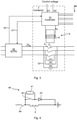
- Figure 4 illustrates an example of a demagnetization circuit 40 connected across the coil 5 and in series with a one-way current conducting device 42.
- the demagnetization circuit comprises an impedance 41, e.g. comprising a resistance, a zener diode and/or any other element able to consume energy when a current flows through it.
- impedance 41 e.g. comprising a resistance, a zener diode and/or any other element able to consume energy when a current flows through it.
- switch 43 may also be opened, connecting the impedance 41 across the coil 5.
- the one-way current conducting device 42 is typically connected anti-parallel to the coil 5, and may comprise a diode such as a freewheeling diode, for preventing transients and maintain an even current in the coil 5.
- FIGS 5a-d illustrate different embodiments of the method of controlling the mechanical contactor 1, of the present invention.
- an indication of unintentional separation of the pair of contacts 2 is obtained S1 while the contactor is in the closed position. Then, in response to the obtained S1 indication, the contactor is opened S2 and the contactor is maintained in its open position by turning off the control current Ic.
- a short circuit protection device (SCPD) 30 is tripped S3, before, after or concurrently with the opening S2 of the contactor, to break the mains current Im outside of the contactor 1.
- the contactor 1 is reset S4, after the opening S2 of the contactor, allowing the contactor to be reclosed by turning on the control current Ic.
- the opening S2 of the contactor results in the contactor being maintained in its open position until the operator 15, be it a human operator or an operating system, actively resets S4 the contactor, e.g. after a predetermined time has elapsed from the opening S2, to allow the contacts 2 to cool down, or after inspecting (e.g. measuring the temperature thereof) the contacts 2 or other parts of the contactor, to ensure that it is safe to reset S4 the contactor to normal operation.
- information is provided S5, after the opening S2, to an operator 15 of the contactor 1, e.g. a human operator or an operating system, about the opening S2.
- This information may e.g. be used by the operator 15 to determine when to reset S4 the contactor, or whether the contactor is in need of service.
- the information may be provided S5 e.g. comprising an alarm signal to an operating system operator 15 and/or via a user interface, such as comprising a display screen and/or light and/or sound indicators, to a human operator 15.
- the obtaining Si of an indication comprises detecting an increased voltage V over the contact pair, e.g. by means of a voltage measuring circuit 33.
- the increased voltage is at least 1 V, e.g. at least 10 V.
- the obtaining Si of an indication comprises detecting an increased mains current Im, e.g. by means of the SCPD 30.
- the electromagnet 4 comprises a demagnetization circuit 40 connected across the coil 5.
- the demagnetization circuit 40 comprises an impedance 41.
- a freewheeling diode 42 is arranged in series with the demagnetization circuit 40, which diode 42 is arranged anti-parallel to the control current Ic.
- the at least one pair of contacts 2 comprises two contact pairs in series which each other.
- the mains current Im is a three-phase current and the at least one pair of contacts 2 comprises a respective contact pair per phase of the three-phase current.
- FIG. 6 schematically illustrates an embodiment of the controller 10 of the present disclosure.
- the controller 10 comprises processing circuitry 11 e.g. a central processing unit (CPU).
- the processing circuitry 11 may comprise one or a plurality of processing units in the form of microprocessor(s).
- ASIC application specific integrated circuit
- FPGA field programmable gate array
- CPLD complex programmable logic device
- the processing circuitry 11 is configured to run one or several computer program(s) or software (SW) 13 stored in a data storage 12 of one or several storage unit(s) e.g. a memory.
- the storage unit is regarded as a computer readable means 12, forming a computer program product together with the SW 13 stored thereon as computer-executable components, as discussed herein and may e.g. be in the form of a Random Access Memory (RAM), a Flash memory or other solid state memory, or a hard disk, or be a combination thereof.
- the processing circuitry 11 may also be configured to store data in the storage 12, as needed.
Landscapes
- Physics & Mathematics (AREA)
- General Physics & Mathematics (AREA)
- Relay Circuits (AREA)
- Emergency Protection Circuit Devices (AREA)
Abstract
Description
- The present disclosure relates to a method of controlling a mechanical contactor.
- A mechanical contactor is a switching device normally intended for performing a high number of switching operations during normal load and overload conditions. The IEC product standard defines a mechanical contactor as a mechanical switching device having only one position of rest, operated otherwise than by hand, capable of making, carrying and breaking currents under normal circuit conditions including operating overload conditions.
- A traditional application is to start, run and stop electrical 3-phase AC-motors just by applying and removing voltage to the circuit. It means that the contactor shall be able to make the inrush current and carry the starting current during a limited time, it shall also be able to carry the normal current during continuous operation and finally break the current when the motor shall be stopped. In some cases, the contactor may also need to break the starting current that can be significantly higher than the normal current and therefore the breaking capacity should be high enough for these cases.
- A short circuit fault is normally not handled by the contactor, but by a Short Circuit Protection Device (SCPD) like for instance fuses or circuit breakers. In case of short circuit, such devices shall clear the fault and prevent hazardous effects. A short circuit is a critical situation for a contactor since the current can be very high, even if the time period with very high current is short, the separation forces on the contacts can be high and the energy dissipated in the device can also be high. The coordination between the SCPD and the contactor can be difficult and is often an issue.
- During a short circuit fault, the large current flowing through the contacts of the contactor induce Lorenz forces which may force the contacts to separate, resulting in an electric arc between the contacts. The arc itself is a plasma but on the contact surfaces there will be melted contact material when the arc is burning. This happens during a normal current breaking procedure as well as during a contact separation caused by a short circuit. However, during a normal breaking procedure, the contacts are brought completely apart, and the arc is extinguished by an extinction system, the current is broken by the contactor itself and the contacts stay in fully open position and cool down. On the other hand, in case of a short circuit, the contacts may be pressed apart unintentionally by the Lorenz forces, creating an arc with melted material on the contact surfaces. When the short circuit is cleared by the SCPD, the separation force disappears and the contacts may again be pressed together. The melted material on the surfaces may then weld together when the contacts cool down and the contactor may no longer be opened since the contacts are stuck in a shorted position. This prevents the contactor from being reused after a short circuit fault.
- It is an objective of the present invention to prevent the welding together of contacts of a contactor as a result of unintentional separation of the contacts.
- According to an aspect of the present invention, there is provided a method of controlling a mechanical contactor comprising at least one pair of contacts for conducting a mains current when the contactor is in a closed position, and an electromagnet arranged to close the contactor, and maintain the contactor in the closed position, by forcing the pair of contacts towards each other when a control current runs through a coil of the electromagnet. The method comprises, while the contactor is in the closed position, obtaining an indication of unintentional separation of the contacts, and in response to the obtained indication, opening the contactor and maintaining the contactor in an open position by turning off the control current.
- According to another aspect of the present invention, there is provided a computer program product comprising computer-executable components for causing a controller to perform an embodiment of the method of the present disclosure when the computer-executable components are run on processing circuitry comprised in the controller.
- According to another aspect of the present invention, there is provided a controller for a mechanical contactor. The controller comprises processing circuitry, and storage storing instructions executable by said processing circuitry whereby said controller is operative to, while the contactor is in the closed position, obtain an indication of unintentional separation of contacts of a pair of contacts of the contactor, for conducting a mains current when the contactor is in the closed position, and to, in response to the obtained indication, open the contactor and maintaining the contactor in an open position by turning off a control current in a coil of an electromagnet arranged to close the contactor, and maintain the contactor in the closed position, by forcing the pair of contacts towards each other when the control current runs through said coil.
- According to another aspect of the present invention, there is provided a mechanical contactor comprising an embodiment of the controller of the present disclosure, the pair of contacts for conducting the mains current when the contactor is in the closed position, and the electromagnet arranged to close the contactor and maintain the contactor in the closed position by forcing the pair of contacts towards each other when the control current runs through the coil of the electromagnet.
- By opening the contactor, including actively separating the contacts and preventing them from reclosing, welding together of the contacts is prevented by allowing them to cool down sufficiently following any arcing there between.
- It is to be noted that any feature of any of the aspects may be applied to any other aspect, wherever appropriate. Likewise, any advantage of any of the aspects may apply to any of the other aspects. Other objectives, features and advantages of the enclosed embodiments will be apparent from the following detailed disclosure, from the attached dependent claims as well as from the drawings.
- Generally, all terms used in the claims are to be interpreted according to their ordinary meaning in the technical field, unless explicitly defined otherwise herein. All references to "a/an/the element, apparatus, component, means, step, etc." are to be interpreted openly as referring to at least one instance of the element, apparatus, component, means, step, etc., unless explicitly stated otherwise. The steps of any method disclosed herein do not have to be performed in the exact order disclosed, unless explicitly stated. The use of "first", "second" etc. for different features/components of the present disclosure are only intended to distinguish the features/components from other similar features/components and not to impart any order or hierarchy to the features/components.
- Embodiments will be described, by way of example, with reference to the accompanying drawings, in which:
-
Fig 1 is a schematic perspective view of a contactor in accordance with some embodiments of the present invention. -
Fig 2 is an illustration of current paths via A-spots and corresponding Lorenz forces between contacts, in accordance with some embodiments of the present invention. -
Fig 3 is a schematic circuit diagram of a contactor and an associated Short-Circuit Protection Device (SCPD), in accordance with some embodiments of the present invention. -
Fig 4 is a schematic circuit diagram of a demagnetizing circuit across the coil of the electromagnet of the contactor, in accordance with some embodiments of the present invention. -
Fig 5a, 5b, 5c and 5d are schematic flow charts of different embodiments of a method of the present invention. -
Fig 6 is a schematic block diagram of a controller, in accordance with some embodiments of the present invention. - Embodiments will now be described more fully hereinafter with reference to the accompanying drawings, in which certain embodiments are shown. However, other embodiments in many different forms are possible within the scope of the present disclosure. Rather, the following embodiments are provided by way of example so that this disclosure will be thorough and complete, and will fully convey the scope of the disclosure to those skilled in the art. Like numbers refer to like elements throughout the description.
-
Figure 1 illustrates acontactor 1 arranged to make, carry and break a main current Im, e.g. between a line and a load. The contactor comprises at least one pair ofcontacts 2, which make the main current Im when brought in contact with each other (closing the contactor, i.e. bringing the contactor from an open position to a closed position), carry the main current when maintained in contact with each other (maintaining the contactor in the closed position), and breaking the main current when separated from each other (opening the contactor, i.e. bringing it from the closed position to the open position). In the embodiment offigure 1 , the contactor comprises two contact pairs in series, eachcontact 2 having acontact surface 2a for making contact with theother contact 2 of its pair. -
Figure 1 illustrates a single-phase contactor 1. However, a corresponding contactor may be designed for any number of phases, e.g. with one or two contact pairs per phase. In case of a three-phase contactor, two contact pairs in series (as infigure 1 ) may be arranged for each phase, for a total of six contact pairs, typically all of which are operated by asingle electromagnet 4. - For operation, the
contactor 1 comprises anelectromagnet 4 functioning as an actuator for closing the contactor, maintaining the contactor in the closed position and opening the contactor, respectively. Theelectromagnet 4 comprises amovable armature 4a and astationary core 4b, around whichcore 4b acoil 5 is wound and arranged to carry a control current Ic. When no control current Ic is flowing through thecoil 5, there is no magnetic attraction between thecore 4b and thearmature 4a, why the armature is held away from the core by means of the separation spring(s) 6 and thecontacts 2 are held separated from each other, i.e. the contactor is in its open position. When the control current Ic is turned on and thus flowing through thecoil 5, the coil and thus theelectromagnet 4 is magnetized whereby thearmature 4a is pulled magnetically towards thecore 4b, bringing the contact pairs in contact with each other and thus bringing the contactor from its open position to its closed position. While the control current Ic is flowing, the contactor remains in the closed position. Optionally, a contact spring 3 is used to evenly press thecontacts 2 against each other while the contactor in the closed position. When the control current Ic is turned off, i.e. not flowing through thecoil 5, the coil 5 (and thus the electromagnet 4) is demagnetized, thearmature 4a is pushed away from thecore 4b by means of theseparation spring 6 and/or the contact spring 3, thecontacts 2 are separated and the contactor is thus brought from its closed position to its open position. - In case of a fault, typically a short circuit fault, when the mains current Im is increased, the
contacts 2 of a contact pair may be forced away from each other by so called Lorenz forces, possibly separating the contacts and allowing an arc to form therebetween while the contactor is in its closed position. If the contactor remains in its closed position by the control current Ic flowing through thecoil 5, thecontacts 2 of the pair may then be forced together again after the fault current is over, by thearmature 4a and/or the contact spring 3. If an arc has melted thecontact surfaces 2a of thecontacts 2 during the fault, the contacts may then be welded together when forced into contact again, making the contactor unusable and in need of service or replacing. - The contactor also comprises a
controller 10, arranged to control the control current Ic, including turning the control current on and off as desired, by means of control signals. Thecontroller 10 may also interact with anoperator 15 of the contactor, e.g. a human operator and/or an operating system. The controller may e.g. provide information about the operation of the contactor to the operator, e.g. to a human operator via a user interface such as a display screen and/or light and/or sound indicators. Such information may be regarding faults or fault induced opening of the contactor. -
Figure 2 illustrates current paths over an interface between twocontacts 2 of a contact pair when thecontactor 1 is in its closed position. It has been found that electric contact is made in very small points called A-spots 21. When twoflat contact surfaces 2a come together the contact is not made over the whole surface but in these specific A-spots 21, the current passing between thecontacts 2 has to pass through the A-spots and the current will be constricted in these points. The constriction of current results in antiparallelcurrent paths 22 and Lorenz forces between thesepaths 22 will create separation forces F on the twocontacts 2. When the current increases, the separation forces F will also increase and there is approximately a square relation between separation force and current, F∼I2. In normal situations and overload situations, the contact spring 3 andelectromagnet 4 must be strong enough to counteract the separation forces, but during e.g. a short circuit fault the separation forces may become so high that the contacts are separated and, in some cases, even theelectromagnet 4 may be forced opened. During such a fault it may be not only the Lorenz forces that effect thecontacts 2 but also the pressure built up by the high energy consumption. - When the
contacts 2 are separated, and a current Im is flowing, an electric arc will be ignited. The arc in itself is a plasma but on thesurfaces 2a, there will be melted contact material when the arc is burning. This typically happens during a normal current breaking procedure as well as during a contact separation caused by a fault current. However, during a normal breaking procedure, thecontacts 2 are brought completely apart, and the arc may be extinguished by an extinction system, the current is broken by thecontactor 1 itself and thecontacts 2 stay fully separated from each other when they cool down. - In contrast, in case of a fault current, the
contacts 2 may be pressed apart unintentionally, creating an arc with melted material on thesurfaces 2a, and when the fault is cleared, e.g. by the SCPD, the separation force F will be reduced allowing thecontacts 2 to be pressed together again. The melted material on thesurfaces 2a may then weld together when thecontacts 2 cool down and thecontactor 1 can no longer be opened since thecontacts 2 are stuck in a shorted position. - For a conventional contactor, the control of a
contactor 1 is just an on/off signal. The contactor is neither an overload detection device nor an SCPD, it just switches the main current Im on and off. The normal behaviour for acontactor 1 is therefore to close or stay closed when the on signal (e.g. from an operator system 15) is activated. Therefore the contactor will normally reclose thecontacts 2 after an unintentional separation of contacts caused by a fault current. This can be avoided by means of embodiments of the present invention. - In accordance with the present invention, the
controller 10 acts to open thecontactor 1, by turning off the control current Ic, upon obtaining an indication of unintentional separation of thecontacts 2 of a contact pair, thus avoiding welding together of the contacts. After allowing time in open position for the contacts to cool down, the contactor may be reset, again allowing the contactor to be closed when an on signal is received by thecontroller 10. The obtained indication may indicate actual separation of thecontacts 2, and/or a formed arc there between, or indicate an elevated risk of such separation or arc. -
Figure 3 illustrates acontactor 1 and its relation to its surroundings. In the embodiment offigure 3 , the main current Im is a three-phase current controlled by thecontactor 1 having pairs ofcontacts 2 for each phase, the opening and closing of which are controlled by thecontroller 10 via the control current Ic as discussed in relation tofigure 1 . - As schematically illustrated in
figure 3 , thecontroller 10 may receive control voltage via terminals A1 and A2. Thecontroller 10 may also interact with the outside of the contactor 1 (e.g. the operator 15) via any input andoutput signals 34 such as serial or digital on/off input signals, serial, digital or visual status output(s), and/or serial, digital or manual reset input signal. - An
SCPD 30 is arranged to break the main current Im upon detection of a fault current, i.e. detecting that the main current increases above a predetermined threshold. In some embodiments of the present invention, the SCPD may cooperate with thecontactor 1. For instance, if the SCPD detects a fault current, it may send anopen contactor signal 32 to thecontroller 10, inducing the controller to turn off the control current Ic, bringing the contactor from its closed position to its open position. Conversely, if thecontroller 10 opens thecontactor 1 in response to an indication of unintentional separation of thecontacts 2, thecontroller 10 may also send atrip signal 31 to the SCPD, inducing the SCPD to break the main current Im. In both cases, the main current Im may be broken by both thecontactor 1 and theSCPD 30. - Thus, one way of detecting a possible unintentional contact separation is to measure the main current Im, and in case of a high current, typically above a predetermined threshold, there is a high probability of contact separation. Therefore a measurement of a high current may provide an indication that the
controller 10 should open the contactor and prevent it from reclosing. Current measurement is often included in anSCPD 30, and in addition to the SCPD itself breaking the current Im it may send asignal 32 to thecontactor 1 so that it also opens. - Another way of detecting a possible unintentional contact separation is by measuring the voltage V across the
contacts 2, by means of avoltage measuring circuit 33. An increased voltage over a contact pair is indicative of separation and an arc burning between them. If thecontacts 2 are in contact with each other, the voltage V will be very low, typically << 1 V, and be proportional to the impedance and current Im in the circuit (the impedance of a closed contact is normally very low). When an arc is ignited, the voltage V will immediately step up, e.g. to a magnitude of about 10 V on each contact pair. For short distances, the voltage V is mainly defined by the anode and cathode of the arc. For two contact pairs in series as infigure1 , if arcs are burning on both contact pairs, the voltage V will step up doubly, e.g. to a magnitude of about 20 V. This measured increased voltage will be created immediately when thecontacts 2 are separated even if the distance between them is only parts of a millimetre. If the distance between thecontacts 2 is further increased, the arc is stretched out and the voltage V will increase further. - To avoid reclosing of a contact pair after unintentional separation of the
contacts 2 thereof, it is desirable to be able to quickly open the contactor by demagnetizing thecoil 5. However, when thecontroller 10 turns off the control current Ic, typically by removing a voltage source therefore, the control current Ic decays during a period of time before the energy stored in thecoil 5 is completely consumed. Thus, in order to further reduce the risk of welding together ofcontacts 2 following unintentional separation thereof, it may be desirable to shorten the time period for demagnetization of the coil. -
Figure 4 illustrates an example of ademagnetization circuit 40 connected across thecoil 5 and in series with a one-waycurrent conducting device 42. The demagnetization circuit comprises animpedance 41, e.g. comprising a resistance, a zener diode and/or any other element able to consume energy when a current flows through it. When turning off the control current Ic, e.g. by openingswitch 44, and it's desired to quickly decrease the control current Ic, switch 43 may also be opened, connecting theimpedance 41 across thecoil 5. The one-waycurrent conducting device 42 is typically connected anti-parallel to thecoil 5, and may comprise a diode such as a freewheeling diode, for preventing transients and maintain an even current in thecoil 5. -
Figures 5a-d illustrate different embodiments of the method of controlling themechanical contactor 1, of the present invention. - According to the embodiments of
figure 5a , an indication of unintentional separation of the pair ofcontacts 2 is obtained S1 while the contactor is in the closed position. Then, in response to the obtained S1 indication, the contactor is opened S2 and the contactor is maintained in its open position by turning off the control current Ic. - According to the embodiment of
figure 5b , which may be combined with any of the embodiments offigures 5a, 5c, and 5d , a short circuit protection device (SCPD) 30 is tripped S3, before, after or concurrently with the opening S2 of the contactor, to break the mains current Im outside of thecontactor 1. - According to the embodiment of
figure 5c , which may be combined with any of the embodiments offigures 5a, 5b, and 5d , thecontactor 1 is reset S4, after the opening S2 of the contactor, allowing the contactor to be reclosed by turning on the control current Ic. In some embodiments, the opening S2 of the contactor results in the contactor being maintained in its open position until theoperator 15, be it a human operator or an operating system, actively resets S4 the contactor, e.g. after a predetermined time has elapsed from the opening S2, to allow thecontacts 2 to cool down, or after inspecting (e.g. measuring the temperature thereof) thecontacts 2 or other parts of the contactor, to ensure that it is safe to reset S4 the contactor to normal operation. - According to the embodiment of
figure 5d , which may be combined with any of the embodiments offigures 5a, 5b, and 5c , information is provided S5, after the opening S2, to anoperator 15 of thecontactor 1, e.g. a human operator or an operating system, about the opening S2. This information may e.g. be used by theoperator 15 to determine when to reset S4 the contactor, or whether the contactor is in need of service. The information may be provided S5 e.g. comprising an alarm signal to anoperating system operator 15 and/or via a user interface, such as comprising a display screen and/or light and/or sound indicators, to ahuman operator 15. - In some embodiments of the present invention, the obtaining Si of an indication comprises detecting an increased voltage V over the contact pair, e.g. by means of a
voltage measuring circuit 33. In some embodiments, the increased voltage is at least 1 V, e.g. at least 10 V. - In some embodiments of the present invention, the obtaining Si of an indication comprises detecting an increased mains current Im, e.g. by means of the
SCPD 30. - In some embodiments of the present invention, the
electromagnet 4 comprises ademagnetization circuit 40 connected across thecoil 5. In some embodiments, thedemagnetization circuit 40 comprises animpedance 41. In some embodiments, a freewheelingdiode 42 is arranged in series with thedemagnetization circuit 40, whichdiode 42 is arranged anti-parallel to the control current Ic. - In some embodiments of the present invention, the at least one pair of
contacts 2 comprises two contact pairs in series which each other. - In some embodiments of the present invention, the mains current Im is a three-phase current and the at least one pair of
contacts 2 comprises a respective contact pair per phase of the three-phase current. -
Figure 6 schematically illustrates an embodiment of thecontroller 10 of the present disclosure. Thecontroller 10 comprises processingcircuitry 11 e.g. a central processing unit (CPU). Theprocessing circuitry 11 may comprise one or a plurality of processing units in the form of microprocessor(s). However, other suitable devices with computing capabilities could be comprised in theprocessing circuitry 11, e.g. an application specific integrated circuit (ASIC), a field programmable gate array (FPGA) or a complex programmable logic device (CPLD). Theprocessing circuitry 11 is configured to run one or several computer program(s) or software (SW) 13 stored in adata storage 12 of one or several storage unit(s) e.g. a memory. The storage unit is regarded as a computer readable means 12, forming a computer program product together with the SW 13 stored thereon as computer-executable components, as discussed herein and may e.g. be in the form of a Random Access Memory (RAM), a Flash memory or other solid state memory, or a hard disk, or be a combination thereof. Theprocessing circuitry 11 may also be configured to store data in thestorage 12, as needed. - The present disclosure has mainly been described above with reference to a few embodiments. However, as is readily appreciated by a person skilled in the art, other embodiments than the ones disclosed above are equally possible within the scope of the present disclosure, as defined by the appended claims.
Claims (15)
- A method of controlling a mechanical contactor (1) comprising:at least one pair of contacts (2) for conducting a mains current (Im) when the contactor is in a closed position; andan electromagnet (4) arranged to close the contactor, and maintain the contactor in the closed position, by forcing the pair of contacts (2) towards each other when a control current (Ic) runs through a coil (5) of the electromagnet;the method comprising:while the contactor is in the closed position, obtaining (Si) an indication of unintentional separation of the contacts (2) of the pair; andin response to the obtained (S1) indication, opening (S2) the contactor and maintaining the contactor in an open position by turning off the control current (Ic).
- The method of claim 1, wherein the obtaining (S1) an indication comprises detecting an increased voltage over the contact pair.
- The method of claim 2, wherein the increased voltage is at least 1 V, e.g. at least 10 V.
- The method of any preceding claim, wherein the obtaining (S1) an indication comprises detecting an increased mains current (Im), e.g. by means of a short circuit protection device, SCPD, (30).
- The method of any preceding claim, further comprising:
tripping (S3) a short circuit protection device, SCPD, (30) to break the mains current (Im) outside of the contactor (1). - The method of any preceding claim, further comprising:
resetting (S4) the contactor (1), allowing the contactor to be reclosed by turning on the control current (Ic). - The method of any preceding claim, further comprising:
providing (S5) information to an operator (15) of the contactor (1), e.g. a human operator or an operating system, about the opening (S2). - The method of any preceding claim, wherein the electromagnet (4) comprises a demagnetization circuit (40) connected across the coil (5).
- The method of claim 8, wherein the demagnetization circuit (40) comprises an impedance (41).
- The method of claim 9, wherein a freewheeling diode (42) is arranged in series with the demagnetization circuit (40), which diode (42) is arranged anti-parallel to the control current (Ic).
- The method of any preceding claim, wherein the at least one pair of contacts (2) comprises two contact pairs in series which each other.
- The method of any preceding claim, wherein the mains current (Im) is a three-phase current and the at least one pair of contacts (2) comprises a respective contact pair per phase of the three-phase current.
- A computer program product (12) comprising computer-executable components (13) for causing a controller (10) to perform the method of any preceding claim when the computer-executable components are run on processing circuitry (11) comprised in the controller.
- A controller (10) for a mechanical contactor (1), the controller comprising:processing circuitry (11); andstorage (12) storing instructions (13) executable by said processing circuitry whereby said controller is operative to:while the contactor is in the closed position, obtain an indication of unintentional separation of contacts (2) of a pair of contacts of the contactor, for conducting a mains current (Im) when the contactor is in the closed position; andin response to the obtained indication, open the contactor and maintaining the contactor in an open position by turning off a control current (Ic) in a coil (5) of an electromagnet (4) arranged to close the contactor, and maintain the contactor in the closed position, by forcing the pair of contacts (2) towards each other when the control current (Ic) runs through said coil (5).
- A mechanical contactor (1) comprising:the controller (10) of claim 14;the pair of contacts (2) for conducting the mains current (Im) when the contactor is in the closed position; andthe electromagnet (4) arranged to close the contactor, and maintain the contactor in the closed position, by forcing the pair of contacts (2) towards each other when the control current (Ic) runs through the coil (5) of the electromagnet.
Priority Applications (5)
| Application Number | Priority Date | Filing Date | Title |
|---|---|---|---|
| EP20196398.0A EP3971927B1 (en) | 2020-09-16 | 2020-09-16 | Contactor control |
| KR1020237011489A KR102800140B1 (en) | 2020-09-16 | 2021-08-06 | Contactor Control |
| US18/044,591 US11887795B2 (en) | 2020-09-16 | 2021-08-06 | Contactor control |
| PCT/EP2021/072000 WO2022058089A1 (en) | 2020-09-16 | 2021-08-06 | Contactor control |
| CN202180061564.4A CN116325055B (en) | 2020-09-16 | 2021-08-06 | Contactor control |
Applications Claiming Priority (1)
| Application Number | Priority Date | Filing Date | Title |
|---|---|---|---|
| EP20196398.0A EP3971927B1 (en) | 2020-09-16 | 2020-09-16 | Contactor control |
Publications (2)
| Publication Number | Publication Date |
|---|---|
| EP3971927A1 true EP3971927A1 (en) | 2022-03-23 |
| EP3971927B1 EP3971927B1 (en) | 2025-12-17 |
Family
ID=72521505
Family Applications (1)
| Application Number | Title | Priority Date | Filing Date |
|---|---|---|---|
| EP20196398.0A Active EP3971927B1 (en) | 2020-09-16 | 2020-09-16 | Contactor control |
Country Status (5)
| Country | Link |
|---|---|
| US (1) | US11887795B2 (en) |
| EP (1) | EP3971927B1 (en) |
| KR (1) | KR102800140B1 (en) |
| CN (1) | CN116325055B (en) |
| WO (1) | WO2022058089A1 (en) |
Cited By (3)
| Publication number | Priority date | Publication date | Assignee | Title |
|---|---|---|---|---|
| US20230170171A1 (en) * | 2021-11-29 | 2023-06-01 | Airbus Operations Sas | Electromechanical switching device for an electric power circuit comprising at least one system for detecting the contact or non-contact position of a blade of a contactor |
| EP4539074A1 (en) * | 2023-10-10 | 2025-04-16 | Schneider Electric Industries Sas | Contactor and control method thereof |
| EP4614544A1 (en) * | 2024-03-06 | 2025-09-10 | ABB Schweiz AG | Switching apparatus for electrical systems and control method thereof |
Families Citing this family (1)
| Publication number | Priority date | Publication date | Assignee | Title |
|---|---|---|---|---|
| US20260011512A1 (en) * | 2024-07-05 | 2026-01-08 | Te Connectivity Solutions Gmbh | Power Switching Device with Self Diagnostic Capability |
Citations (3)
| Publication number | Priority date | Publication date | Assignee | Title |
|---|---|---|---|---|
| EP0694937A2 (en) * | 1994-07-29 | 1996-01-31 | Siemens Aktiengesellschaft | Method and apparatus for determining the residual life of contacts in switching devices |
| EP2317527A1 (en) * | 2009-10-28 | 2011-05-04 | Delphi Technologies, Inc. | System for preventive diagnosis of contact impedance and overloads of a commutator |
| WO2015070893A1 (en) * | 2013-11-12 | 2015-05-21 | Abb Technology Ltd | Method for controlling a contactor device, and control unit |
Family Cites Families (15)
| Publication number | Priority date | Publication date | Assignee | Title |
|---|---|---|---|---|
| US2942155A (en) * | 1956-12-17 | 1960-06-21 | Mc Graw Edison Co | Load-pickup repeating circuit interrupter |
| US3192450A (en) * | 1962-08-01 | 1965-06-29 | Stevens Arnold Inc | Electromagnetic switches of the make-before-break type |
| US3284670A (en) * | 1963-06-17 | 1966-11-08 | Gen Electric | Ground fault responsive control means for an electric circuit recloser or the like |
| FR2606929B1 (en) * | 1986-11-14 | 1989-02-10 | Telemecanique Electrique | SWITCHING DEVICE FOR PROTECTIVE APPARATUS |
| DE19544926C1 (en) | 1995-12-01 | 1997-04-30 | Siemens Ag | Method and device for monitoring the erosion of the contact pieces in a switching device |
| DE19734224C1 (en) | 1997-08-07 | 1999-02-04 | Siemens Ag | Method and device for determining switchgear-specific data on contacts in switchgear and / or for determining company-specific data in the network connected with it |
| US6377143B1 (en) * | 2001-03-16 | 2002-04-23 | Eaton Corporation | Weld-free contact system for electromagnetic contactors |
| CN101095205B (en) * | 2004-11-05 | 2010-11-10 | 通用电气公司 | Electrical contactor and related contactor closure control method |
| US8094426B2 (en) * | 2009-06-02 | 2012-01-10 | Eaton Corporation | Electrical switching apparatus providing coordinated opening with a circuit interrupter and method of operating the same |
| WO2012072810A1 (en) | 2010-12-02 | 2012-06-07 | Abb Research Ltd | Method and device for monitoring switching devices |
| KR101563587B1 (en) * | 2011-07-25 | 2015-10-27 | 엘에스산전 주식회사 | Power transmisson device for vacuum interrupter |
| US8638531B2 (en) | 2011-12-14 | 2014-01-28 | Eaton Corporation | Hybrid bi-directional DC contactor and method of controlling thereof |
| EP2831898B1 (en) * | 2012-03-30 | 2016-03-30 | ABB Technology Ltd. | Electrical circuit switch |
| DE102014203424A1 (en) * | 2014-02-26 | 2015-09-10 | Robert Bosch Gmbh | Battery system and method of operating such |
| CN105225895B (en) | 2015-10-13 | 2018-06-29 | 青岛博瑞电气有限公司 | A kind of intelligent DC contactor |
-
2020
- 2020-09-16 EP EP20196398.0A patent/EP3971927B1/en active Active
-
2021
- 2021-08-06 CN CN202180061564.4A patent/CN116325055B/en active Active
- 2021-08-06 US US18/044,591 patent/US11887795B2/en active Active
- 2021-08-06 WO PCT/EP2021/072000 patent/WO2022058089A1/en not_active Ceased
- 2021-08-06 KR KR1020237011489A patent/KR102800140B1/en active Active
Patent Citations (3)
| Publication number | Priority date | Publication date | Assignee | Title |
|---|---|---|---|---|
| EP0694937A2 (en) * | 1994-07-29 | 1996-01-31 | Siemens Aktiengesellschaft | Method and apparatus for determining the residual life of contacts in switching devices |
| EP2317527A1 (en) * | 2009-10-28 | 2011-05-04 | Delphi Technologies, Inc. | System for preventive diagnosis of contact impedance and overloads of a commutator |
| WO2015070893A1 (en) * | 2013-11-12 | 2015-05-21 | Abb Technology Ltd | Method for controlling a contactor device, and control unit |
Cited By (4)
| Publication number | Priority date | Publication date | Assignee | Title |
|---|---|---|---|---|
| US20230170171A1 (en) * | 2021-11-29 | 2023-06-01 | Airbus Operations Sas | Electromechanical switching device for an electric power circuit comprising at least one system for detecting the contact or non-contact position of a blade of a contactor |
| US12381056B2 (en) * | 2021-11-29 | 2025-08-05 | Airbus Operations Sas | Electromechanical switching device for an electric power circuit comprising at least one system for detecting the contact or non-contact position of a blade of a contactor |
| EP4539074A1 (en) * | 2023-10-10 | 2025-04-16 | Schneider Electric Industries Sas | Contactor and control method thereof |
| EP4614544A1 (en) * | 2024-03-06 | 2025-09-10 | ABB Schweiz AG | Switching apparatus for electrical systems and control method thereof |
Also Published As
| Publication number | Publication date |
|---|---|
| CN116325055B (en) | 2024-05-28 |
| CN116325055A (en) | 2023-06-23 |
| US11887795B2 (en) | 2024-01-30 |
| WO2022058089A1 (en) | 2022-03-24 |
| KR20230066579A (en) | 2023-05-16 |
| EP3971927B1 (en) | 2025-12-17 |
| KR102800140B1 (en) | 2025-04-28 |
| US20230335359A1 (en) | 2023-10-19 |
Similar Documents
| Publication | Publication Date | Title |
|---|---|---|
| US11887795B2 (en) | Contactor control | |
| US4223365A (en) | Auto resetting switchgear trip indicator circuits | |
| JP5284352B2 (en) | Switching using microelectromechanical systems | |
| US20110046808A1 (en) | Controller and system including a controller for detecting a failure thereof | |
| CN102005720B (en) | Neutral line breakage detection protection method and device | |
| US20120133477A1 (en) | Renewable one-time load break contactor | |
| EP3896811B1 (en) | Contactor control device and power supply system | |
| US20160035509A1 (en) | Circuit breaking arrangement | |
| CN118043923A (en) | Protective switching device | |
| US4096366A (en) | Means for detecting a loss of vacuum in vacuum-type circuit interrupters used in polyphase a.c. vacuum circuit breaker | |
| AU2002313978B2 (en) | Apparatus and method for servicing a distribution bus | |
| JP4172916B2 (en) | Short-circuit protection device | |
| EP1919053B1 (en) | State monitoring device for circuit breaker | |
| US7872552B2 (en) | Method and device for the secure operation of a switching device | |
| KR100304252B1 (en) | Auto-Switching Control Apparatus of Interlock Air Circuit Breaker | |
| US3454831A (en) | Quick-opening,low cost,current limiting circuit breaker | |
| JP2017199505A (en) | Circuit breaker | |
| US20250079101A1 (en) | Magnetic switch for hybrid circuit breaker applications | |
| JP2603140B2 (en) | Selective shutoff method | |
| RU2786938C1 (en) | Three-phase high voltage vacuum circuit breaker control device | |
| CA1081325A (en) | Means for detecting a loss of vacuum in vacuum-type circuit interrupters used in a polyphase a.c. vacuum circuit breaker | |
| RU57050U1 (en) | DC CIRCUIT BREAKER BY CONTACT SWITCHING MACHINE | |
| US2393061A (en) | Control system | |
| JP2015226403A (en) | Phase loss prevention circuit | |
| KR20210130489A (en) | Earth Leakage Trip Device |
Legal Events
| Date | Code | Title | Description |
|---|---|---|---|
| PUAI | Public reference made under article 153(3) epc to a published international application that has entered the european phase |
Free format text: ORIGINAL CODE: 0009012 |
|
| STAA | Information on the status of an ep patent application or granted ep patent |
Free format text: STATUS: THE APPLICATION HAS BEEN PUBLISHED |
|
| AK | Designated contracting states |
Kind code of ref document: A1 Designated state(s): AL AT BE BG CH CY CZ DE DK EE ES FI FR GB GR HR HU IE IS IT LI LT LU LV MC MK MT NL NO PL PT RO RS SE SI SK SM TR |
|
| STAA | Information on the status of an ep patent application or granted ep patent |
Free format text: STATUS: REQUEST FOR EXAMINATION WAS MADE |
|
| 17P | Request for examination filed |
Effective date: 20220602 |
|
| RBV | Designated contracting states (corrected) |
Designated state(s): AL AT BE BG CH CY CZ DE DK EE ES FI FR GB GR HR HU IE IS IT LI LT LU LV MC MK MT NL NO PL PT RO RS SE SI SK SM TR |
|
| STAA | Information on the status of an ep patent application or granted ep patent |
Free format text: STATUS: EXAMINATION IS IN PROGRESS |
|
| 17Q | First examination report despatched |
Effective date: 20240403 |
|
| GRAP | Despatch of communication of intention to grant a patent |
Free format text: ORIGINAL CODE: EPIDOSNIGR1 |
|
| STAA | Information on the status of an ep patent application or granted ep patent |
Free format text: STATUS: GRANT OF PATENT IS INTENDED |
|
| INTG | Intention to grant announced |
Effective date: 20250711 |
|
| GRAS | Grant fee paid |
Free format text: ORIGINAL CODE: EPIDOSNIGR3 |
|
| GRAA | (expected) grant |
Free format text: ORIGINAL CODE: 0009210 |
|
| STAA | Information on the status of an ep patent application or granted ep patent |
Free format text: STATUS: THE PATENT HAS BEEN GRANTED |
|
| AK | Designated contracting states |
Kind code of ref document: B1 Designated state(s): AL AT BE BG CH CY CZ DE DK EE ES FI FR GB GR HR HU IE IS IT LI LT LU LV MC MK MT NL NO PL PT RO RS SE SI SK SM TR |
|
| REG | Reference to a national code |
Ref country code: CH Ref legal event code: F10 Free format text: ST27 STATUS EVENT CODE: U-0-0-F10-F00 (AS PROVIDED BY THE NATIONAL OFFICE) Effective date: 20251217 Ref country code: GB Ref legal event code: FG4D |
|
| REG | Reference to a national code |
Ref country code: DE Ref legal event code: R096 Ref document number: 602020063935 Country of ref document: DE |
|
| REG | Reference to a national code |
Ref country code: LT Ref legal event code: MG9D |
|
| PG25 | Lapsed in a contracting state [announced via postgrant information from national office to epo] |
Ref country code: NO Free format text: LAPSE BECAUSE OF FAILURE TO SUBMIT A TRANSLATION OF THE DESCRIPTION OR TO PAY THE FEE WITHIN THE PRESCRIBED TIME-LIMIT Effective date: 20260317 |
|
| PG25 | Lapsed in a contracting state [announced via postgrant information from national office to epo] |
Ref country code: FI Free format text: LAPSE BECAUSE OF FAILURE TO SUBMIT A TRANSLATION OF THE DESCRIPTION OR TO PAY THE FEE WITHIN THE PRESCRIBED TIME-LIMIT Effective date: 20251217 Ref country code: HR Free format text: LAPSE BECAUSE OF FAILURE TO SUBMIT A TRANSLATION OF THE DESCRIPTION OR TO PAY THE FEE WITHIN THE PRESCRIBED TIME-LIMIT Effective date: 20251217 |
|
| PG25 | Lapsed in a contracting state [announced via postgrant information from national office to epo] |
Ref country code: RS Free format text: LAPSE BECAUSE OF FAILURE TO SUBMIT A TRANSLATION OF THE DESCRIPTION OR TO PAY THE FEE WITHIN THE PRESCRIBED TIME-LIMIT Effective date: 20260317 |
|
| REG | Reference to a national code |
Ref country code: NL Ref legal event code: MP Effective date: 20251217 |
|
| PG25 | Lapsed in a contracting state [announced via postgrant information from national office to epo] |
Ref country code: LV Free format text: LAPSE BECAUSE OF FAILURE TO SUBMIT A TRANSLATION OF THE DESCRIPTION OR TO PAY THE FEE WITHIN THE PRESCRIBED TIME-LIMIT Effective date: 20251217 |
|
| PG25 | Lapsed in a contracting state [announced via postgrant information from national office to epo] |
Ref country code: BG Free format text: LAPSE BECAUSE OF FAILURE TO SUBMIT A TRANSLATION OF THE DESCRIPTION OR TO PAY THE FEE WITHIN THE PRESCRIBED TIME-LIMIT Effective date: 20251217 |