EP3971873A1 - Bezel connection structure and display - Google Patents
Bezel connection structure and display Download PDFInfo
- Publication number
- EP3971873A1 EP3971873A1 EP20830847.8A EP20830847A EP3971873A1 EP 3971873 A1 EP3971873 A1 EP 3971873A1 EP 20830847 A EP20830847 A EP 20830847A EP 3971873 A1 EP3971873 A1 EP 3971873A1
- Authority
- EP
- European Patent Office
- Prior art keywords
- connection
- frame
- connection portion
- products
- limiting
- Prior art date
- Legal status (The legal status is an assumption and is not a legal conclusion. Google has not performed a legal analysis and makes no representation as to the accuracy of the status listed.)
- Pending
Links
Images


Classifications
-
- G—PHYSICS
- G09—EDUCATION; CRYPTOGRAPHY; DISPLAY; ADVERTISING; SEALS
- G09F—DISPLAYING; ADVERTISING; SIGNS; LABELS OR NAME-PLATES; SEALS
- G09F15/00—Boards, hoardings, pillars, or like structures for notices, placards, posters, or the like
- G09F15/0006—Boards, hoardings, pillars, or like structures for notices, placards, posters, or the like planar structures comprising one or more panels
- G09F15/0012—Boards, hoardings, pillars, or like structures for notices, placards, posters, or the like planar structures comprising one or more panels frames therefor
-
- B—PERFORMING OPERATIONS; TRANSPORTING
- B21—MECHANICAL METAL-WORKING WITHOUT ESSENTIALLY REMOVING MATERIAL; PUNCHING METAL
- B21D—WORKING OR PROCESSING OF SHEET METAL OR METAL TUBES, RODS OR PROFILES WITHOUT ESSENTIALLY REMOVING MATERIAL; PUNCHING METAL
- B21D53/00—Making other particular articles
- B21D53/74—Making other particular articles frames for openings, e.g. for windows, doors, handbags
-
- G—PHYSICS
- G09—EDUCATION; CRYPTOGRAPHY; DISPLAY; ADVERTISING; SEALS
- G09F—DISPLAYING; ADVERTISING; SIGNS; LABELS OR NAME-PLATES; SEALS
- G09F15/00—Boards, hoardings, pillars, or like structures for notices, placards, posters, or the like
- G09F15/0006—Boards, hoardings, pillars, or like structures for notices, placards, posters, or the like planar structures comprising one or more panels
- G09F15/0018—Boards, hoardings, pillars, or like structures for notices, placards, posters, or the like planar structures comprising one or more panels panel clamping or fastening means
-
- H—ELECTRICITY
- H05—ELECTRIC TECHNIQUES NOT OTHERWISE PROVIDED FOR
- H05K—PRINTED CIRCUITS; CASINGS OR CONSTRUCTIONAL DETAILS OF ELECTRIC APPARATUS; MANUFACTURE OF ASSEMBLAGES OF ELECTRICAL COMPONENTS
- H05K5/00—Casings, cabinets or drawers for electric apparatus
- H05K5/0017—Casings, cabinets or drawers for electric apparatus with operator interface units
-
- G—PHYSICS
- G02—OPTICS
- G02F—OPTICAL DEVICES OR ARRANGEMENTS FOR THE CONTROL OF LIGHT BY MODIFICATION OF THE OPTICAL PROPERTIES OF THE MEDIA OF THE ELEMENTS INVOLVED THEREIN; NON-LINEAR OPTICS; FREQUENCY-CHANGING OF LIGHT; OPTICAL LOGIC ELEMENTS; OPTICAL ANALOGUE/DIGITAL CONVERTERS
- G02F1/00—Devices or arrangements for the control of the intensity, colour, phase, polarisation or direction of light arriving from an independent light source, e.g. switching, gating or modulating; Non-linear optics
- G02F1/01—Devices or arrangements for the control of the intensity, colour, phase, polarisation or direction of light arriving from an independent light source, e.g. switching, gating or modulating; Non-linear optics for the control of the intensity, phase, polarisation or colour
- G02F1/13—Devices or arrangements for the control of the intensity, colour, phase, polarisation or direction of light arriving from an independent light source, e.g. switching, gating or modulating; Non-linear optics for the control of the intensity, phase, polarisation or colour based on liquid crystals, e.g. single liquid crystal display cells
- G02F1/133—Constructional arrangements; Operation of liquid crystal cells; Circuit arrangements
- G02F1/1333—Constructional arrangements; Manufacturing methods
- G02F1/133308—Support structures for LCD panels, e.g. frames or bezels
- G02F1/133328—Segmented frames
Definitions
- the present disclosure relates to the display field, and in particular, to a frame connection structure and a display including the frame connection structure.
- a frame in the prior art includes a first case 50, a second case 60 and a connection piece 70. Two ends of the connection piece are respectively inserted into the first case 50 and the second case 60, and are fixedly connected to the first case 50 and the second case 60 through a plurality of screws.
- This kind of splicing method is more complicated, the low assembly efficiency, and the connection is fixed by screws, which causes that appearance gap is not easy to control.
- Embodiments of the present disclosure provide a frame connection structure and a display.
- the frame connection structure has a simple integral structure, simple processing, easy assembly, and high reliability.
- An embodiment according to a first aspect of the present disclosure provides a frame connection structure, comprising: a first frame, on which a first connection portion is provided; and a second frame, on which a second connection portion is provided, wherein the first connection portion is in lap joint with the second connection portion, and the first frame abuts against one end of the second connection portion.
- connection structure provided by the present disclosure, the first frame and the second frame are fixedly connected through the cooperation of the first connection portion and the second connection portion.
- the cooperation structure of the first connection portion and the second connection portion is simple. On the one hand, production and manufacturing are easy, thereby improving a production efficiency of products, and further reducing the production and manufacturing cost of products. On the other hand, assembly is convenient for an operator, that is, an assembly efficiency of products is improved, thereby improving a production efficiency of products, and further reducing the production and manufacturing cost of products.
- first connection portion is in lap joint with the second connection portion, and the first connection portion and the second connection portion partially overlap, thereby ensuring the connection area between the first connection portion and the second connection portion, and improving the connection strength of products, and further extending the service life of products.
- the second connection portion includes a supporting portion and two limiting plates, wherein the supporting portion is in lap joint with the first connection portion, the first frame abuts against a first end of the supporting portion, and the two limiting plates are symmetrically arranged on both sides of the supporting portion for limiting the movement of the first connection portion in a first direction.
- a limiting portion is provided on one end of the first connection portion, the limiting portion is clamped on a second end of the supporting portion for limiting the movement of the first connection portion in a second direction.
- a mounting groove is provided on the second connection portion, and the first connection portion is fixed in the mounting groove.
- a first positioning portion is provided on one end of the first connection portion, and a second positioning portion that cooperates with the first positioning portion is provided on the second frame.
- the first positioning portion is a limiting protrusion
- the second positioning portion is a limiting groove
- the limiting protrusion is inserted into the limiting groove
- the first positioning portion is a first inserting piece
- the second positioning portion is a second inserting piece
- the first inserting piece is plugged into the second inserting piece.
- the first connection portion is provided with a plurality of convex portions
- the second connection portion is provided with a plurality of concave portions that cooperate with the convex portions.
- the second connection portion is provided with a threaded hole
- the first connection portion is provided with a connection hole
- the connection hole is arranged corresponding to the threaded hole
- the first connection portion and the second connection portion are fixedly connected through a screw.
- An embodiment according to a second aspect of the present disclosure provides a display, comprising any one of the frame connection structures described above.
- the display provided by the present disclosure has high frame connection reliability and long service life, thereby improving the market competitiveness of products.
- first frame 10 first connection portion 20, limiting portion 21, connection hole 22, second frame 30, second connection portion 40, supporting portion 41, limiting plate 42, threaded hole 43, first case 50, second case 60, connection piece 70.
- each embodiment represents a single combination of elements of the utility model
- the elements of different embodiments of the present disclosure can be replaced or combined. Therefore, the present disclosure may also be considered to include all possible combinations of elements in the same and/or different embodiments described. Therefore, if one embodiment includes elements A, B, and C, and another embodiment includes a combination of elements B and D, the present disclosure is also deemed to include embodiments of all other possible combinations including one or more elements of A, B, C, and D, which although may not be clearly described in the following contents.
- the frame connection structure provided by an embodiment according to the first aspect of the present disclosure includes: a first frame 10 and a second frame 30.
- a first connection portion 20 is provided on the first frame 10.
- a second connection portion 40 is provided on the second frame 30, and the first connection portion 20 is in lap joint with the second connection portion 40.
- the first frame 10 abuts against one end of the second connection portion 40.
- connection structure provided by the present disclosure, the first frame 10 and the second frame 30 are fixedly connected through the cooperation of the first connection portion 20 and the second connection portion 40.
- the cooperation structure of the first connection portion 20 and the second connection portion 40 is simple. On the one hand, production and manufacturing are easy, thereby improving a production efficiency of products, and further reducing the production and manufacturing cost of products. On the other hand, assembly is convenient for an operator, that is, an assembly efficiency of products is improved, thereby improving a production efficiency of products, and further reducing the production and manufacturing cost of products.
- first connection portion 20 is in lap joint with the second connection portion 40, and the first connection portion 20 and the second connection portion 40 partially overlap, which ensure the connection area between the first connection portion 20 and the second connection portion 40, thereby improving the connection strength of products, and further extending the service life of products.
- the second connection portion 40 includes: a supporting portion 41 and two limiting plates 42.
- the supporting portion 41 is in lap joint with the first connection portion 20, and the first frame 10 abuts against a first end of the supporting portion 41.
- the two limiting plates 42 are symmetrically arranged on both sides of the supporting portion 41 for limiting the movement of the first connection portion 20 in a first direction.
- the limiting plate 42 plays a role in positioning, so as to prevent deviation of the first connection portion 20 during the installation process, which causes inaccurate positioning between the second connection portion 40 and the first connection portion 20, thereby ensuring an installation accuracy of products, and further reducing an unqualified rate of products.
- a limiting portion 21 is provided on one end of the first connection portion 20, and the limiting portion 21 is clamped on a second end of the supporting portion 41 for limiting the movement of the first connection portion 20 in a second direction.
- the first end and the second end of the supporting portion are opposite ends of the supporting portion.
- the cooperation of the limiting portion 21 and the limiting plate 42 can achieve accurate positioning of products.
- the installation accuracy of products is ensured, thereby reducing the unqualified rate of products.
- the assembly efficiency of products is improved, thereby reducing the production and manufacturing cost of products.
- a mounting groove is provided on the second connection portion, and the first connection portion is fixed in the mounting groove.
- the mounting groove plays a role in positioning, which can quickly install the first connection portion and the second connection portion together, thereby improving the assembly efficiency of products, and further reducing the production and manufacturing cost of products and increasing the production and manufacturing cost of products.
- a first positioning portion is provided on one end of the first connection portion, and the second frame is provided with a second positioning portion that cooperates with the first positioning portion.
- the cooperation of the first positioning portion and the second positioning portion can achieve accurate positioning of products, thereby ensuring the installation accuracy of products, and further reducing the unqualified rate of products.
- the cooperation of the first positioning portion and the second positioning portion can achieve rapid positioning of products, thereby improving the assembly efficiency of products, and further reducing the production and manufacturing cost of products.
- the first positioning portion is a limiting protrusion
- the second positioning portion is a limiting groove
- the limiting protrusion is inserted into the limiting groove
- the cooperation structure of the limiting protrusion and the limiting groove is simple.
- production and manufacturing are easy, thereby improving the production efficiency of products, and further reducing the production and manufacturing cost of products.
- assembly is convenient for an operator, that is, the assembly efficiency of products is improved, thereby improving the production efficiency of products, and further reducing the production and manufacturing cost of products.
- the first positioning portion is a first inserting piece
- the second positioning portion is a second inserting piece
- the first inserting piece is plugged into the second inserting piece
- the cooperation structure of the first inserting piece and the second inserting piece is simple, which can achieve rapid positioning of products, thereby improving the assembly efficiency of products, and further reducing the production and manufacturing cost of products.
- the first connection portion is provided with a plurality of convex portions
- the second connection portion is provided with a plurality of concave portions that cooperate with the convex portions
- the plurality of convex portions provided on the first connection portion cooperate with the concave portions on the second connection portion cooperate, which can achieve rapid positioning of products, thereby improving the assembly efficiency of products, and further reducing the production and manufacturing cost of products.
- the second connection portion 40 is provided with a threaded hole 43
- the first connection portion 20 is provided with a connection hole 22
- the connection hole 22 is arranged corresponding to the threaded hole 43, and the first connection portion 20 and the second connection portion 40 are fixedly connected through a screw.
- the screw fixing-connection method has a simple structure, low price, and convenient assembly and disassembly, which improves the assembly efficiency of products, thereby improving the production efficiency of products, and further reducing the production and manufacturing cost of products.
- the connection is reliable and strong by the screw fixing-connection method, thereby ensuring a prolonged service life of products.
- a display provided by an embodiment according to the second aspect of the present disclosure includes any one of the frame connection structures described above.
- the display provided by the present disclosure has high frame connection reliability and a long service life, thereby improving a market competitiveness of products.
- connection can be a fixed connection, a detachable connection, or an integral connection.
- Connect can be direct connection or indirect connection through an intermediary.
Landscapes
- Engineering & Computer Science (AREA)
- Physics & Mathematics (AREA)
- General Physics & Mathematics (AREA)
- Theoretical Computer Science (AREA)
- Microelectronics & Electronic Packaging (AREA)
- Mechanical Engineering (AREA)
- Devices For Indicating Variable Information By Combining Individual Elements (AREA)
- Mirrors, Picture Frames, Photograph Stands, And Related Fastening Devices (AREA)
- Connection Of Plates (AREA)
Abstract
Description
- The present disclosure claims the priority of a patent application with the Application No.
201920991454.8 and the title "FRAME CONNECTION STRUCTURE AND DISPLAY", which is filed to CNIPA on June 27, 2019 - The present disclosure relates to the display field, and in particular, to a frame connection structure and a display including the frame connection structure.
- With the development of technology, the market demand for displays and TVs is increasing, and the market for frames of displays and TV used therewith has also expanded. As shown in
Fig. 5 , a frame in the prior art includes afirst case 50, asecond case 60 and aconnection piece 70. Two ends of the connection piece are respectively inserted into thefirst case 50 and thesecond case 60, and are fixedly connected to thefirst case 50 and thesecond case 60 through a plurality of screws. This kind of splicing method is more complicated, the low assembly efficiency, and the connection is fixed by screws, which causes that appearance gap is not easy to control. - Embodiments of the present disclosure provide a frame connection structure and a display. The frame connection structure has a simple integral structure, simple processing, easy assembly, and high reliability.
- An embodiment according to a first aspect of the present disclosure provides a frame connection structure, comprising: a first frame, on which a first connection portion is provided; and a second frame, on which a second connection portion is provided, wherein the first connection portion is in lap joint with the second connection portion, and the first frame abuts against one end of the second connection portion.
- In the connection structure provided by the present disclosure, the first frame and the second frame are fixedly connected through the cooperation of the first connection portion and the second connection portion. The cooperation structure of the first connection portion and the second connection portion is simple. On the one hand, production and manufacturing are easy, thereby improving a production efficiency of products, and further reducing the production and manufacturing cost of products. On the other hand, assembly is convenient for an operator, that is, an assembly efficiency of products is improved, thereby improving a production efficiency of products, and further reducing the production and manufacturing cost of products. In addition, the first connection portion is in lap joint with the second connection portion, and the first connection portion and the second connection portion partially overlap, thereby ensuring the connection area between the first connection portion and the second connection portion, and improving the connection strength of products, and further extending the service life of products.
- Optionally, the second connection portion includes a supporting portion and two limiting plates, wherein the supporting portion is in lap joint with the first connection portion, the first frame abuts against a first end of the supporting portion, and the two limiting plates are symmetrically arranged on both sides of the supporting portion for limiting the movement of the first connection portion in a first direction.
- Optionally, a limiting portion is provided on one end of the first connection portion, the limiting portion is clamped on a second end of the supporting portion for limiting the movement of the first connection portion in a second direction.
- Optionally, a mounting groove is provided on the second connection portion, and the first connection portion is fixed in the mounting groove.
- Optionally, a first positioning portion is provided on one end of the first connection portion, and a second positioning portion that cooperates with the first positioning portion is provided on the second frame.
- Optionally, the first positioning portion is a limiting protrusion, the second positioning portion is a limiting groove, and the limiting protrusion is inserted into the limiting groove.
- Optionally, the first positioning portion is a first inserting piece, the second positioning portion is a second inserting piece, and the first inserting piece is plugged into the second inserting piece.
- Optionally, the first connection portion is provided with a plurality of convex portions, and the second connection portion is provided with a plurality of concave portions that cooperate with the convex portions.
- Optionally, the second connection portion is provided with a threaded hole, the first connection portion is provided with a connection hole, the connection hole is arranged corresponding to the threaded hole, and the first connection portion and the second connection portion are fixedly connected through a screw.
- An embodiment according to a second aspect of the present disclosure provides a display, comprising any one of the frame connection structures described above.
- The display provided by the present disclosure has high frame connection reliability and long service life, thereby improving the market competitiveness of products.
- It is to be understood that both the above general description and the following detailed description only are exemplary and explanatory, which cannot limit the present disclosure.
- In order to more clearly describe the technical embodiments in the embodiments of the present disclosure, these embodiments or the drawings that need to be used in the description of the prior art will be briefly described hereinafter.
-
Fig. 1 is a three-dimensional structure diagram of the frame connection structure according to an embodiment of the present disclosure. -
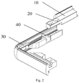
Fig. 2 is a schematic diagram of an exploded structure of the frame connection structure shown inFig. 1 . -
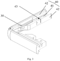
Fig. 3 is a schematic diagram of a three-dimensional structure of the second frame according to an embodiment of the present disclosure. -
Fig. 4 is a schematic diagram of a three-dimensional structure of the first frame according to an embodiment of the present disclosure. -
Fig. 5 is a schematic diagram of an exploded structure of the frame connection structure in the prior art. - In the drawings, a corresponding relationship between reference numbers and component names in
Figs. 1 to 5 is:
first frame 10,first connection portion 20, limitingportion 21,connection hole 22,second frame 30,second connection portion 40, supportingportion 41, limitingplate 42, threadedhole 43,first case 50,second case 60,connection piece 70. - The following discussion provides several embodiments of the present disclosure. Although each embodiment represents a single combination of elements of the utility model, the elements of different embodiments of the present disclosure can be replaced or combined. Therefore, the present disclosure may also be considered to include all possible combinations of elements in the same and/or different embodiments described. Therefore, if one embodiment includes elements A, B, and C, and another embodiment includes a combination of elements B and D, the present disclosure is also deemed to include embodiments of all other possible combinations including one or more elements of A, B, C, and D, which although may not be clearly described in the following contents.
- As shown in
Figs. 1 and2 , the frame connection structure provided by an embodiment according to the first aspect of the present disclosure includes: afirst frame 10 and asecond frame 30. - Specifically, a
first connection portion 20 is provided on thefirst frame 10. Asecond connection portion 40 is provided on thesecond frame 30, and thefirst connection portion 20 is in lap joint with thesecond connection portion 40. Thefirst frame 10 abuts against one end of thesecond connection portion 40. - In the connection structure provided by the present disclosure, the
first frame 10 and thesecond frame 30 are fixedly connected through the cooperation of thefirst connection portion 20 and thesecond connection portion 40. The cooperation structure of thefirst connection portion 20 and thesecond connection portion 40 is simple. On the one hand, production and manufacturing are easy, thereby improving a production efficiency of products, and further reducing the production and manufacturing cost of products. On the other hand, assembly is convenient for an operator, that is, an assembly efficiency of products is improved, thereby improving a production efficiency of products, and further reducing the production and manufacturing cost of products. In addition, thefirst connection portion 20 is in lap joint with thesecond connection portion 40, and thefirst connection portion 20 and thesecond connection portion 40 partially overlap, which ensure the connection area between thefirst connection portion 20 and thesecond connection portion 40, thereby improving the connection strength of products, and further extending the service life of products. - As shown in
Fig. 3 , in an embodiment of the present disclosure, thesecond connection portion 40 includes: a supportingportion 41 and twolimiting plates 42. - The supporting
portion 41 is in lap joint with thefirst connection portion 20, and thefirst frame 10 abuts against a first end of the supportingportion 41. The twolimiting plates 42 are symmetrically arranged on both sides of the supportingportion 41 for limiting the movement of thefirst connection portion 20 in a first direction. - In this embodiment, the
limiting plate 42 plays a role in positioning, so as to prevent deviation of thefirst connection portion 20 during the installation process, which causes inaccurate positioning between thesecond connection portion 40 and thefirst connection portion 20, thereby ensuring an installation accuracy of products, and further reducing an unqualified rate of products. - As shown in
Fig. 4 , in an embodiment of the present disclosure, alimiting portion 21 is provided on one end of thefirst connection portion 20, and thelimiting portion 21 is clamped on a second end of the supportingportion 41 for limiting the movement of thefirst connection portion 20 in a second direction. The first end and the second end of the supporting portion are opposite ends of the supporting portion. - In this embodiment, the cooperation of the
limiting portion 21 and thelimiting plate 42 can achieve accurate positioning of products. On the one hand, the installation accuracy of products is ensured, thereby reducing the unqualified rate of products. On the other hand, the assembly efficiency of products is improved, thereby reducing the production and manufacturing cost of products. - In an embodiment of the present disclosure, a mounting groove is provided on the second connection portion, and the first connection portion is fixed in the mounting groove.
- In this embodiment, the mounting groove plays a role in positioning, which can quickly install the first connection portion and the second connection portion together, thereby improving the assembly efficiency of products, and further reducing the production and manufacturing cost of products and increasing the production and manufacturing cost of products.
- In an embodiment of the present disclosure, a first positioning portion is provided on one end of the first connection portion, and the second frame is provided with a second positioning portion that cooperates with the first positioning portion.
- In this embodiment, the cooperation of the first positioning portion and the second positioning portion can achieve accurate positioning of products, thereby ensuring the installation accuracy of products, and further reducing the unqualified rate of products. In addition, the cooperation of the first positioning portion and the second positioning portion can achieve rapid positioning of products, thereby improving the assembly efficiency of products, and further reducing the production and manufacturing cost of products.
- In an embodiment of the present disclosure, the first positioning portion is a limiting protrusion, the second positioning portion is a limiting groove, and the limiting protrusion is inserted into the limiting groove.
- In this embodiment, the cooperation structure of the limiting protrusion and the limiting groove is simple. On the one hand, production and manufacturing are easy, thereby improving the production efficiency of products, and further reducing the production and manufacturing cost of products. On the other hand, assembly is convenient for an operator, that is, the assembly efficiency of products is improved, thereby improving the production efficiency of products, and further reducing the production and manufacturing cost of products.
- In an embodiment of the present disclosure, the first positioning portion is a first inserting piece, the second positioning portion is a second inserting piece, and the first inserting piece is plugged into the second inserting piece.
- In this embodiment, the cooperation structure of the first inserting piece and the second inserting piece is simple, which can achieve rapid positioning of products, thereby improving the assembly efficiency of products, and further reducing the production and manufacturing cost of products.
- In an embodiment of the present disclosure, the first connection portion is provided with a plurality of convex portions, and the second connection portion is provided with a plurality of concave portions that cooperate with the convex portions.
- In this embodiment, the plurality of convex portions provided on the first connection portion cooperate with the concave portions on the second connection portion cooperate, which can achieve rapid positioning of products, thereby improving the assembly efficiency of products, and further reducing the production and manufacturing cost of products.
- In an embodiment of the present disclosure, as shown in
Fig. 3 , thesecond connection portion 40 is provided with a threadedhole 43, and as shown inFig. 2 thefirst connection portion 20 is provided with aconnection hole 22, theconnection hole 22 is arranged corresponding to the threadedhole 43, and thefirst connection portion 20 and thesecond connection portion 40 are fixedly connected through a screw. - In this embodiment, the screw fixing-connection method has a simple structure, low price, and convenient assembly and disassembly, which improves the assembly efficiency of products, thereby improving the production efficiency of products, and further reducing the production and manufacturing cost of products. In addition, the connection is reliable and strong by the screw fixing-connection method, thereby ensuring a prolonged service life of products.
- A display provided by an embodiment according to the second aspect of the present disclosure includes any one of the frame connection structures described above.
- The display provided by the present disclosure has high frame connection reliability and a long service life, thereby improving a market competitiveness of products.
- In the present disclosure, the terms "first" and "second" are only used for descriptive purposes, and cannot be understood as indicating or implying relative importance. The terms "install", "connect with", "connect", "fix" and other terms should be understood in a broad sense. For example, "connect" can be a fixed connection, a detachable connection, or an integral connection. "Connect" can be direct connection or indirect connection through an intermediary. For those skilled in the art, the specific meanings of the above-mentioned terms in the present disclosure can be understood according to specific circumstances.
- The foregoing descriptions are only preferred embodiments of the present disclosure, and are not intended to limit the present disclosure. For those skilled in the art, the present disclosure can have various modifications and changes. Any modification, equivalent replacement, improvement, etc. made within the spirit and principle of the present disclosure shall be included in the scope of the present disclosure.
Claims (10)
- A frame connection structure, comprising:a first frame, on which a first connection portion is provided; anda second frame, on which a second connection portion is provided, wherein the first connection portion is in lap joint with the second connection portion, and the first frame abuts against one end of the second connection portion.
- The frame connection structure according to claim 1, wherein
the second connection portion comprises:a supporting portion, wherein the supporting portion is in lap joint with the first connection portion, and the first frame abuts against a first end of the supporting portion; andtwo limiting plates, wherein the two limiting plates are symmetrically arranged on both sides of the supporting portion for limiting the movement of the first connection portion in a first direction. - The frame connection structure according to claim 2, wherein
a limiting portion is provided on one end of the first connection portion, the limiting portion is clamped on a second end of the supporting portion for limiting the movement of the first connection portion in a second direction. - The frame connection structure according to claim 1, wherein
a mounting groove is provided on the second connection portion, and the first connection portion is fixed in the mounting groove. - The frame connection structure according to claim 4, wherein
a first positioning portion is provided on one end of the first connection portion, and a second positioning portion that cooperates with the first positioning portion is provided on the second frame. - The frame connection structure according to claim 5, wherein
the first positioning portion is the limiting protrusion, the second positioning portion is the limiting groove, and the limiting protrusion is inserted into the limiting groove. - The frame connection structure according to claim 5, wherein
the first positioning portion is a first inserting piece, the second positioning portion is a second inserting piece, and the first inserting piece is plugged into the second inserting piece. - The frame connection structure according to claim 1, wherein
the first connection portion is provided with a plurality of convex portions, and the second connection portion is provided with a plurality of concave portions that cooperate with the convex portions. - The frame connection structure according to claim 1, wherein
the second connection portion is provided with a threaded hole, the first connection portion is provided with a connection hole, the connection hole is arranged corresponding to the threaded hole, and the first connection portion and the second connection portion are fixedly connected through a screw. - A display, comprising a frame connection structure according to any one of claims 1 to 9.
Applications Claiming Priority (2)
| Application Number | Priority Date | Filing Date | Title |
|---|---|---|---|
| CN201920991454.8U CN210244877U (en) | 2019-06-27 | 2019-06-27 | Frame connection structure and display |
| PCT/CN2020/098594 WO2020259695A1 (en) | 2019-06-27 | 2020-06-28 | Bezel connection structure and display |
Publications (2)
| Publication Number | Publication Date |
|---|---|
| EP3971873A1 true EP3971873A1 (en) | 2022-03-23 |
| EP3971873A4 EP3971873A4 (en) | 2022-07-13 |
Family
ID=69988397
Family Applications (1)
| Application Number | Title | Priority Date | Filing Date |
|---|---|---|---|
| EP20830847.8A Pending EP3971873A4 (en) | 2019-06-27 | 2020-06-28 | BEZEL CONNECTION STRUCTURE AND DISPLAY |
Country Status (6)
| Country | Link |
|---|---|
| US (1) | US11991839B2 (en) |
| EP (1) | EP3971873A4 (en) |
| JP (1) | JP7683157B2 (en) |
| KR (1) | KR102698391B1 (en) |
| CN (1) | CN210244877U (en) |
| WO (1) | WO2020259695A1 (en) |
Families Citing this family (2)
| Publication number | Priority date | Publication date | Assignee | Title |
|---|---|---|---|---|
| CN210244877U (en) * | 2019-06-27 | 2020-04-03 | 广州视源电子科技股份有限公司 | Frame connection structure and display |
| CN115616804A (en) * | 2022-09-09 | 2023-01-17 | 东莞市中天弘浩电子有限公司 | High brightness module screen |
Family Cites Families (23)
| Publication number | Priority date | Publication date | Assignee | Title |
|---|---|---|---|---|
| JPH07102685A (en) * | 1993-09-30 | 1995-04-18 | Ibiden Co Ltd | Wall panel and frame for wall panel |
| JP3539547B2 (en) * | 1999-04-30 | 2004-07-07 | 株式会社新鋭産業 | LCD display frame |
| JP2001067012A (en) * | 1999-08-26 | 2001-03-16 | Sanyo Electric Co Ltd | Display module and its installation structure |
| KR101073037B1 (en) * | 2004-01-07 | 2011-10-12 | 삼성전자주식회사 | Chassis frame and liquid crystal display having the same |
| JP2007086625A (en) * | 2005-09-26 | 2007-04-05 | Sharp Corp | Display device |
| JP4709000B2 (en) * | 2005-12-26 | 2011-06-22 | 日電精密工業株式会社 | Thin display frame |
| JP4419985B2 (en) * | 2006-04-28 | 2010-02-24 | 船井電機株式会社 | Liquid crystal display |
| US20110209431A1 (en) * | 2006-12-20 | 2011-09-01 | Jochu Thchnology Co., Ltd. | Easy-to-be-assembled double-face bezel structure and assembling method thereof |
| TWI323149B (en) * | 2006-12-20 | 2010-04-01 | Jochu Technology Co Ltd | Structure of one piece-form 3-d bezel and manufacturing method thereof |
| KR101262179B1 (en) * | 2007-01-19 | 2013-05-14 | 삼성디스플레이 주식회사 | Display device and case for the same |
| JP5056042B2 (en) * | 2007-02-08 | 2012-10-24 | 船井電機株式会社 | Liquid crystal display |
| JP2009282215A (en) * | 2008-05-21 | 2009-12-03 | Funai Electric Co Ltd | Thin display device |
| CN201265940Y (en) * | 2008-09-01 | 2009-07-01 | 蔡勇祥 | Non-frame buckling type forced sealing air conditioner box |
| KR200456259Y1 (en) | 2011-04-11 | 2011-10-20 | 에스지피코리아 (주) | Case for portable electronic device |
| CN102778766A (en) * | 2011-05-13 | 2012-11-14 | 英业达股份有限公司 | Display and method for assembling same |
| US20130256245A1 (en) * | 2012-03-27 | 2013-10-03 | Shenzhen China Star Optoelectronics Technology Co., Ltd. | Plastic frame, frame unit and fastener thereof |
| CN203182405U (en) * | 2013-02-07 | 2013-09-11 | 江门市盈江科技有限公司 | Teaching board frame connecting structure |
| CN203776451U (en) * | 2013-10-18 | 2014-08-20 | 张莉欣 | Frame assembly and buckle-joint mechanism |
| JP2016066950A (en) * | 2014-09-25 | 2016-04-28 | シャープ株式会社 | Display device and television receiver |
| CN207252108U (en) * | 2017-08-31 | 2018-04-17 | 广州视源电子科技股份有限公司 | Frame structure and double-color frame of display device |
| CN208367662U (en) * | 2018-06-14 | 2019-01-11 | 广州视源电子科技股份有限公司 | Interactive intelligent tablet computer and frame assembly thereof |
| CN109117029B (en) * | 2018-08-29 | 2021-01-19 | 广州创知科技有限公司 | Lower frame and assembling method thereof, touch frame and assembling method thereof, and touch screen |
| CN210244877U (en) * | 2019-06-27 | 2020-04-03 | 广州视源电子科技股份有限公司 | Frame connection structure and display |
-
2019
- 2019-06-27 CN CN201920991454.8U patent/CN210244877U/en active Active
-
2020
- 2020-06-28 WO PCT/CN2020/098594 patent/WO2020259695A1/en not_active Ceased
- 2020-06-28 KR KR1020227002519A patent/KR102698391B1/en active Active
- 2020-06-28 JP JP2021575907A patent/JP7683157B2/en active Active
- 2020-06-28 EP EP20830847.8A patent/EP3971873A4/en active Pending
-
2021
- 2021-12-27 US US17/562,868 patent/US11991839B2/en active Active
Also Published As
| Publication number | Publication date |
|---|---|
| KR102698391B1 (en) | 2024-08-22 |
| WO2020259695A1 (en) | 2020-12-30 |
| US20220124914A1 (en) | 2022-04-21 |
| KR20220069918A (en) | 2022-05-27 |
| JP7683157B2 (en) | 2025-05-27 |
| JP2022538039A (en) | 2022-08-31 |
| EP3971873A4 (en) | 2022-07-13 |
| US11991839B2 (en) | 2024-05-21 |
| CN210244877U (en) | 2020-04-03 |
Similar Documents
| Publication | Publication Date | Title |
|---|---|---|
| US11991839B2 (en) | Bezel connection structure and display | |
| US10028600B2 (en) | Frame assembly and display device comprising the frame assembly | |
| CN204991019U (en) | Connection structure and display screen of display screen | |
| CN101832496A (en) | Display device and backlight module thereof | |
| CN106932945A (en) | Frame-free displaying device | |
| US11293585B2 (en) | Pedestal, complete machine device and method for assembling the same | |
| CN211294184U (en) | Display screen assembly and intelligent blackboard | |
| US20070279581A1 (en) | Backlight module frame | |
| CN102819285B (en) | Computer all-in-one machine | |
| CN207925024U (en) | A kind of combination mounting structure | |
| CN202419525U (en) | Liquid crystal display and extruded aluminum fixing structure in backlight module thereof | |
| US9411184B2 (en) | Back plate splicing structure for large-size backlight modules and liquid crystal display | |
| CN208430638U (en) | Plane splicing structure for integral bathroom sheet wall | |
| CN110985834A (en) | Wall installation mechanism of wisdom blackboard | |
| CN109764034A (en) | A kind of invisible connecting piece | |
| CN209805292U (en) | Special cable support for tunnel | |
| CN110029756B (en) | Modular frame system | |
| CN207906301U (en) | A kind of bearing hold-down support and drive shaft | |
| CN204854512U (en) | All -screen digital display calliper | |
| CN219225812U (en) | Novel spliced screen display unit | |
| CN105158952A (en) | Display structure | |
| CN223245231U (en) | A snap-connected sign structure | |
| CN221058595U (en) | LED display screen module mounting structure | |
| CN209928838U (en) | Label fixing structure | |
| CN219471525U (en) | An explosion-proof mold easy to assemble aluminum alloy formwork |
Legal Events
| Date | Code | Title | Description |
|---|---|---|---|
| STAA | Information on the status of an ep patent application or granted ep patent |
Free format text: STATUS: THE INTERNATIONAL PUBLICATION HAS BEEN MADE |
|
| PUAI | Public reference made under article 153(3) epc to a published international application that has entered the european phase |
Free format text: ORIGINAL CODE: 0009012 |
|
| STAA | Information on the status of an ep patent application or granted ep patent |
Free format text: STATUS: REQUEST FOR EXAMINATION WAS MADE |
|
| 17P | Request for examination filed |
Effective date: 20211215 |
|
| AK | Designated contracting states |
Kind code of ref document: A1 Designated state(s): AL AT BE BG CH CY CZ DE DK EE ES FI FR GB GR HR HU IE IS IT LI LT LU LV MC MK MT NL NO PL PT RO RS SE SI SK SM TR |
|
| A4 | Supplementary search report drawn up and despatched |
Effective date: 20220614 |
|
| RIC1 | Information provided on ipc code assigned before grant |
Ipc: G09F 15/00 20060101ALI20220609BHEP Ipc: G09F 9/00 20060101AFI20220609BHEP |
|
| DAV | Request for validation of the european patent (deleted) | ||
| DAX | Request for extension of the european patent (deleted) | ||
| STAA | Information on the status of an ep patent application or granted ep patent |
Free format text: STATUS: EXAMINATION IS IN PROGRESS |
|
| 17Q | First examination report despatched |
Effective date: 20250117 |