EP3971868A1 - Aircraft system and method to display air traffic indicators - Google Patents
Aircraft system and method to display air traffic indicators Download PDFInfo
- Publication number
- EP3971868A1 EP3971868A1 EP21198318.4A EP21198318A EP3971868A1 EP 3971868 A1 EP3971868 A1 EP 3971868A1 EP 21198318 A EP21198318 A EP 21198318A EP 3971868 A1 EP3971868 A1 EP 3971868A1
- Authority
- EP
- European Patent Office
- Prior art keywords
- air traffic
- aircraft
- display image
- numerical value
- display
- Prior art date
- Legal status (The legal status is an assumption and is not a legal conclusion. Google has not performed a legal analysis and makes no representation as to the accuracy of the status listed.)
- Granted
Links
Images




Classifications
-
- G—PHYSICS
- G08—SIGNALLING
- G08G—TRAFFIC CONTROL SYSTEMS
- G08G5/00—Traffic control systems for aircraft
- G08G5/20—Arrangements for acquiring, generating, sharing or displaying traffic information
- G08G5/21—Arrangements for acquiring, generating, sharing or displaying traffic information located onboard the aircraft
-
- G—PHYSICS
- G08—SIGNALLING
- G08G—TRAFFIC CONTROL SYSTEMS
- G08G5/00—Traffic control systems for aircraft
- G08G5/50—Navigation or guidance aids
-
- G—PHYSICS
- G08—SIGNALLING
- G08G—TRAFFIC CONTROL SYSTEMS
- G08G5/00—Traffic control systems for aircraft
- G08G5/50—Navigation or guidance aids
- G08G5/55—Navigation or guidance aids for a single aircraft
-
- G—PHYSICS
- G08—SIGNALLING
- G08G—TRAFFIC CONTROL SYSTEMS
- G08G5/00—Traffic control systems for aircraft
- G08G5/70—Arrangements for monitoring traffic-related situations or conditions
- G08G5/72—Arrangements for monitoring traffic-related situations or conditions for monitoring traffic
- G08G5/723—Arrangements for monitoring traffic-related situations or conditions for monitoring traffic from the aircraft
-
- G—PHYSICS
- G08—SIGNALLING
- G08G—TRAFFIC CONTROL SYSTEMS
- G08G5/00—Traffic control systems for aircraft
- G08G5/80—Anti-collision systems
Definitions
- Air traffic density is expected to continue to increase with the advent of urban air mobility (UAM), which could clutter traffic displays.
- UAM may also accelerate a need for single pilot capable systems to keep up with demand.
- inventions of the inventive concepts disclosed herein are directed to a system.
- the system may include at least one display installed in an aircraft.
- the system may include at least one processor installed in the aircraft and communicatively coupled to the at least one display.
- the at least one processor may be configured to: obtain air traffic data associated with air traffic; generate a display image based at least on the air traffic data; and output the display image as graphical data.
- the at least one display may be configured to display the display image to a user.
- the display image may convey a range dimension and a horizontal dimension.
- the display image may depict at least one air traffic indicator.
- Each of the at least one air traffic indicator may be positioned respective to a corresponding range and horizontal location relative to the aircraft.
- Each of the at least one air traffic indicator may indicate at least one of: an amount of a vertical distance of air traffic above the aircraft, an amount of a vertical distance of air traffic below the aircraft, or that air traffic has an approximately equal altitude as the aircraft.
- inventions of the inventive concepts disclosed herein are directed to a method.
- the method may include: obtaining, by at least one processor installed in an aircraft and communicatively coupled to at least one display installed in the aircraft, air traffic data associated with air traffic; generating, by the at least one processor, a display image based at least on the air traffic data; outputting, by the at least one processor, the display image as graphical data; and displaying, by the at least one display, the display image to a user; wherein the display image conveys a range dimension and a horizontal dimension, wherein the display image depicts at least one air traffic indicator, each of the at least one air traffic indicator positioned respective to a corresponding range and horizontal location relative to the aircraft, wherein each of the at least one air traffic indicator indicates at least one of: an amount of a vertical distance of air traffic above the aircraft, an amount of a vertical distance of air traffic below the aircraft, or that air traffic has an approximately equal altitude as the aircraft.
- inventive concepts are not limited in their application to the details of construction and the arrangement of the components or steps or methodologies set forth in the following description or illustrated in the drawings.
- inventive concepts disclosed herein may be practiced without these specific details.
- well-known features may not be described in detail to avoid unnecessarily complicating the instant disclosure.
- inventive concepts disclosed herein are capable of other embodiments or of being practiced or carried out in various ways. Also, it is to be understood that the phraseology and terminology employed herein is for the purpose of description and should not be regarded as limiting.
- a letter following a reference numeral is intended to reference an embodiment of the feature or element that may be similar, but not necessarily identical, to a previously described element or feature bearing the same reference numeral (e.g., 1, 1a, 1b).
- reference numeral e.g. 1, 1a, 1b
- Such shorthand notations are used for purposes of convenience only, and should not be construed to limit the inventive concepts disclosed herein in any way unless expressly stated to the contrary.
- any reference to "one embodiment,” or “some embodiments” means that a particular element, feature, structure, or characteristic described in connection with the embodiment is included in at least one embodiment of the inventive concepts disclosed herein.
- the appearances of the phrase “in some embodiments” in various places in the specification are not necessarily all referring to the same embodiment, and embodiments of the inventive concepts disclosed may include one or more of the features expressly described or inherently present herein, or any combination of sub-combination of two or more such features, along with any other features which may not necessarily be expressly described or inherently present in the instant disclosure.
- embodiments of the inventive concepts disclosed herein may be directed to a system (e.g., an aircraft system) and a method configured to display at least one air traffic indicator.
- Some embodiments may provide comprehensive graphics that declutter the display, which may be important in reducing pilot workload for single pilot operation.
- Some embodiments may simplify traffic avoidance while increasing operational efficiency and improving safety.
- Some embodiments may consolidate information of air traffic within a single air traffic indicator. For example, filling a top-half of the air traffic indicator with a top-half numerical value may indicate traffic above an ownship by an amount indicated by the top-half numerical value. For example, filling a bottom-half of the air traffic indicator with a bottom-half numerical value may indicate traffic below an ownship by an amount indicated by the bottom-half numerical value.
- Some embodiments may include a priority scheme where, if air traffic includes at least two aircraft that if depicted separately would have overlapping air traffic indicators, a combined air traffic indicator representing the at least two aircraft may be used. For example, if two aircraft are both above or both below, the combined air traffic indicator may indicate a numerical value for the vertically closest aircraft to the ownship due to greater proximity threat.
- FIGS. 1A, 1B , 1C, 1D , and 2 exemplary embodiments of at least one air traffic indicator 102 that may be depicted in a display image 200 are shown.
- the display image 200 may convey a range dimension and a horizontal dimension.
- the display image 200 may depict at least one air traffic indicator 102.
- Each of the at least one air traffic indicator 102 may be positioned (e.g., in the display image 200) respective to a corresponding range and horizontal location relative to a position of the aircraft (e.g., 302), wherein each of the at least one air traffic indicator indicates at least one of: an amount of a vertical distance of air traffic (e.g., an air traffic target) above the aircraft (e.g., 302), an amount of a vertical distance of air traffic (e.g., an air traffic target) below the aircraft (e.g., 302), or that air traffic (e.g., an air traffic target) has an approximately equal altitude as the aircraft (e.g., 302).
- an amount of a vertical distance of air traffic e.g., an air traffic target
- an air traffic target e.g., an air traffic target
- Each of the three air traffic indicators 102 may depict at least one numerical value (e.g., a top-half numerical value 102A, bottom-half numerical value 102B, and/or a zero value 102N).
- a first air traffic indicator 102 may have a top-half numerical value 102A positioned in a top half of the first air traffic indicator 102
- a second air traffic indicator 102 may have a bottom-half numerical value 102B positioned in a bottom half of the second air traffic indicator 102
- a third air traffic indicator 102 may have a zero value 102N.
- the top-half numerical value 102A may indicate the amount (e.g., "45” indicates air traffic is 4,500 feet above the aircraft) of the vertical distance of the air traffic (e.g., an air traffic target) above the aircraft (e.g., 302).
- the bottom-half numerical value 102B may indicate the amount (e.g., "25” indicates air traffic is 2,500 feet below the aircraft) of the vertical distance of the air traffic (e.g., an air traffic target) below the aircraft (e.g., 302).
- the zero value 102N may indicate that the air traffic (e.g., an air traffic target) has an approximately equal (e.g., 0 +/- 50 feet) altitude as the aircraft (e.g., 302).
- Each air traffic indicator 102 may have any suitable geometric shape (e.g., defined by at least one line and/or at least one curve; e.g., a diamond shape, as shown).
- some air traffic indicators 102 may be combined aircraft indicators (e.g., 102-3, 102-6, or 102-9). If air traffic includes at least two aircraft that if depicted separately would have overlapping air traffic indicators 102 (e.g., 102-1, 102-2, 102-4, 102-5, 102-7, and/or 102-8), a combined air traffic indicator (e.g., 102-3, 102-6, or 102-9) representing the at least two aircraft can be used to declutter the display image 200.
- a combined air traffic indicator e.g., 102-3, 102-6, or 102-9 representing the at least two aircraft can be used to declutter the display image 200.
- a combined air traffic indicator 102-3 representing the two air traffic targets can be used to declutter the display image 200.
- the combined air traffic indicator 102-3 can include a top-half numerical value 102A and a bottom-half numerical value 102B.
- a combined air traffic indicator 102-6 representing the two air traffic targets can be used to declutter the display image 200.
- the combined air traffic indicator 102-6 can include a top-half numerical value 102A for the air traffic target that is vertically closest to the aircraft (e.g., 302) as that is the closest threat to the aircraft (e.g., 302).
- a combined air traffic indicator 102-9 representing the two air traffic targets can be used to declutter the display image 200.
- the combined air traffic indicator 102-9 can include a bottom-half numerical value 102B for the air traffic target that is vertically closest to the aircraft (e.g., 302) as that is the closest threat to the aircraft (e.g., 302).
- the display image 200 depicting air traffic indicators 102 is shown.
- the display image 200 may convey a range dimension and a horizontal dimension.
- the display image 200 may depict at least one air traffic indicator 102.
- Each of the at least one air traffic indicator 102 may be positioned (e.g., in the display image 200) respective to a corresponding range and horizontal location relative to a position of the aircraft (e.g., 302).
- the system may include an aircraft 302, which may include at least one user (e.g., flight crew and/or pilot(s)), at least one display unit computing device 304, at least one aircraft computing device 306, at least one automatic dependent surveillance-broadcast (ADS-B) computing device 308, and/or at least one user interface 310, some or all of which may be communicatively coupled at any given time.
- at least one user e.g., flight crew and/or pilot(s)
- ADS-B automatic dependent surveillance-broadcast
- the at least one display unit computing device 304, the at least one aircraft computing device 306, the at least one ADS-B computing device 308, and/or the at least one user interface 310 may be implemented as a single computing device or any number of computing devices configured to perform (e.g., collectively perform if more than one computing device) any or all of the operations disclosed throughout.
- the at least one display unit computing device 304, the at least one aircraft computing device 306, the at least one ADS-B computing device 308, and/or the at least one user interface 310 may be installed in the aircraft 302.
- the user may be a pilot or crew member.
- the user may interface with the system 300 via the at least one user interface 310.
- the at least one user interface 310 may be implemented as any suitable user interface, such as a touchscreen (e.g., of the display unit computing device 304 and/or another display unit), a multipurpose control panel, a control panel integrated into a flight deck, a cursor control panel (CCP) (sometimes referred to as a display control panel (DCP)), a keyboard, a mouse, a trackpad, at least one hardware button, a switch, an eye tracking system, and/or a voice recognition system.
- a touchscreen e.g., of the display unit computing device 304 and/or another display unit
- CCP cursor control panel
- DCP display control panel
- the user interface 310 may be configured to receive at least one user input and to output the at least one user input to a computing device (e.g., 304, 306, and/or 308).
- a pilot of the aircraft 104 may be able to interface with the user interface 310 to: engage (or disengage) a mode to cause the display image 200 to be displayed.
- such user inputs may be output to the ADS-B computing device 308 and/or the display unit computing device 304.
- the display unit computing device 304 may be implemented as any suitable computing device, such as a primary flight display (PFD) computing device and/or a multifunction window (MFW) display computing device. As shown in FIG. 4 , the display unit computing device 304 may include at least one display 402, at least one processor 404, at least one memory 406, and/or at least one storage 410, some or all of which may be communicatively coupled at any given time.
- PFD primary flight display
- MMW multifunction window
- the at least one processor 404 may include at least one central processing unit (CPU), at least one graphics processing unit (GPU), at least one field-programmable gate array (FPGA), at least one application specific integrated circuit (ASIC), at least one digital signal processor, at least one virtual machine (VM) running on at least one processor, and/or the like configured to perform (e.g., collectively perform) any of the operations disclosed throughout.
- the at least one processor 404 may include a CPU and a GPU configured to perform (e.g., collectively perform) any of the operations disclosed throughout.
- the processor 404 may be configured to run various software applications or computer code stored (e.g., maintained) in a non-transitory computer-readable medium (e.g., memory 406 and/or storage 410) and configured to execute various instructions or operations.
- the processor 404 may be configured to perform any or all of the operations disclosed throughout.
- the processor 404 may be configured to: obtain air traffic data (e.g., automatic dependent surveillance-broadcast (ADS-B) data from the ADS-B computing device 308) associated with air traffic; obtain aircraft data (e.g., from the computing device 306); generate a display image 200 based at least on the air traffic data and/or the aircraft data; and/or output the display image 200 as graphical data.
- the display 402 may be configured to display the display image 200 to a user.
- the at least one aircraft computing device 306 may be implemented as any suitable computing device, such as a flight management system (FMS) computing device or a flight data computer.
- the at least one aircraft computing device 306 may include any or all of the elements, as shown in FIG. 5 .
- the aircraft computing device 306 may include at least one processor 502, at least one memory 504, and/or at least one storage 506, some or all of which may be communicatively coupled at any given time.
- the at least one processor 502 may include at least one central processing unit (CPU), at least one graphics processing unit (GPU), at least one field-programmable gate array (FPGA), at least one application specific integrated circuit (ASIC), at least one digital signal processor, at least one virtual machine (VM) running on at least one processor, and/or the like configured to perform (e.g., collectively perform) any of the operations disclosed throughout.
- the at least one processor 502 may include a CPU and a GPU configured to perform (e.g., collectively perform) any of the operations disclosed throughout.
- the processor 502 may be configured to run various software applications (e.g., an FMS application) or computer code stored (e.g., maintained) in a non-transitory computer-readable medium (e.g., memory 504 and/or storage 506) and configured to execute various instructions or operations.
- the processor 502 of the aircraft computing device 306 may be configured to perform any or all of the operations disclosed throughout.
- the processor 502 of the computing device 210A may be configured to: output aircraft data (e.g., FMS data, flight path data, inertial reference unit (IRU) data, flight data, and/or flight computer data) to the display unit computing device 304 and/or the ADS-B computing device 308.
- aircraft data e.g., FMS data, flight path data, inertial reference unit (IRU) data, flight data, and/or flight computer data
- the at least one ADS-B computing device 308 may be implemented as any suitable computing device, such as an ADS-B receiver computing device.
- the at least one ADS-B computing device 308 may include any or all of the elements shown in FIG. 6 .
- the ADS-B computing device 308 may include at least one antenna 601, at least one processor 602, at least one memory 604, and/or at least one storage 606, some or all of which may be communicatively coupled at any given time.
- the at least one processor 602 may include at least one central processing unit (CPU), at least one graphics processing unit (GPU), at least one field-programmable gate array (FPGA), at least one application specific integrated circuit (ASIC), at least one digital signal processor, at least one virtual machine (VM) running on at least one processor, and/or the like configured to perform (e.g., collectively perform) any of the operations disclosed throughout.
- the at least one processor 602 may include a CPU and a GPU configured to perform (e.g., collectively perform) any of the operations disclosed throughout.
- the processor 602 may be configured to run various software applications (e.g., an ADS-B application) or computer code stored (e.g., maintained) in a non-transitory computer-readable medium (e.g., memory 604 and/or storage 606) and configured to execute various instructions or operations.
- the processor 602 of the ADS-B computing device 308 may be configured to perform any or all of the operations disclosed throughout.
- the processor 602 may be configured to: obtain air traffic data; and/or output air traffic data to the display unit computing device 304 and/or the aircraft computing device 306.
- At least one processor may be configured to (e.g., collectively configured to, if more than one processor): obtain air traffic data associated with air traffic; generate a display image 200 based at least on the air traffic data; and output the display image 200 as graphical data.
- At least one processor e.g., the at least one processor 404, the at least one processor 502, and/or the at least one processor 602 of the aircraft 302 may be configured to perform (e.g., collectively perform) any or all of the operations disclosed throughout.
- an exemplary embodiment of a method 700 may include one or more of the following steps. Additionally, for example, some embodiments may include performing one or more instances of the method 700 iteratively, concurrently, and/or sequentially. Additionally, for example, at least some of the steps of the method 700 may be performed in parallel and/or concurrently. Additionally, in some embodiments, at least some of the steps of the method 700 may be performed non-sequentially.
- a step 702 may include obtaining, by at least one processor installed in an aircraft and communicatively coupled to at least one display installed in the aircraft, air traffic data associated with air traffic.
- a step 704 may include generating, by the at least one processor, a display image based at least on the air traffic data.
- a step 706 may include outputting, by the at least one processor, the display image as graphical data.
- a step 708 may include displaying, by the at least one display, the display image to a user, wherein the display image conveys a range dimension and a horizontal dimension, wherein the display image depicts at least one air traffic indicator, each of the at least one air traffic indicator positioned respective to a corresponding range and horizontal location relative to the aircraft, wherein each of the at least one air traffic indicator indicates at least one of: an amount of a vertical distance of air traffic above the aircraft, an amount of a vertical distance of air traffic below the aircraft, or that air traffic has an approximately equal altitude as the aircraft.
- method 700 may include any of the operations disclosed throughout.
- embodiments of the inventive concepts disclosed herein may be directed to a system (e.g., an aircraft system) and a method configured to display at least one air traffic indicator.
- a system e.g., an aircraft system
- a method configured to display at least one air traffic indicator.
- At least one non-transitory computer-readable medium may refer to as at least one non-transitory computer-readable medium (e.g., at least one computer-readable medium implemented as hardware; e.g., at least one non-transitory processor-readable medium, at least one memory (e.g., at least one nonvolatile memory, at least one volatile memory, or a combination thereof; e.g., at least one random-access memory, at least one flash memory, at least one read-only memory (ROM) (e.g., at least one electrically erasable programmable read-only memory (EEPROM)), at least one on-processor memory (e.g., at least one on-processor cache, at least one on-processor buffer, at least one on-processor flash memory, at least one on-processor EEPROM, or a combination thereof), or a combination thereof), at least one storage device (e.g., at least one hard-disk drive, at
- At least one means one or a plurality of; for example, “at least one” may comprise one, two, three, ..., one hundred, or more.
- one or more means one or a plurality of; for example, “one or more” may comprise one, two, three, ..., one hundred, or more.
- zero or more means zero, one, or a plurality of; for example, “zero or more” may comprise zero, one, two, three, ..., one hundred, or more.
- the methods, operations, and/or functionality disclosed may be implemented as sets of instructions or software readable by a device. Further, it is understood that the specific order or hierarchy of steps in the methods, operations, and/or functionality disclosed are examples of exemplary approaches. Based upon design preferences, it is understood that the specific order or hierarchy of steps in the methods, operations, and/or functionality can be rearranged while remaining within the scope of the claims. The accompanying claims may present elements of the various steps in a sample order, and are not necessarily meant to be limited to the specific order or hierarchy presented.
- embodiments of the methods according to the inventive concepts disclosed herein may include one or more of the steps described herein. Further, such steps may be carried out in any desired order and two or more of the steps may be carried out simultaneously with one another. Two or more of the steps disclosed herein may be combined in a single step, and in some embodiments, one or more of the steps may be carried out as two or more sub-steps. Further, other steps or sub-steps may be carried in addition to, or as substitutes to one or more of the steps disclosed herein.
Landscapes
- Engineering & Computer Science (AREA)
- Aviation & Aerospace Engineering (AREA)
- Physics & Mathematics (AREA)
- General Physics & Mathematics (AREA)
- Radar, Positioning & Navigation (AREA)
- Remote Sensing (AREA)
- Traffic Control Systems (AREA)
Abstract
Description
- Air traffic density is expected to continue to increase with the advent of urban air mobility (UAM), which could clutter traffic displays. UAM may also accelerate a need for single pilot capable systems to keep up with demand.
- In one aspect, embodiments of the inventive concepts disclosed herein are directed to a system. The system may include at least one display installed in an aircraft. The system may include at least one processor installed in the aircraft and communicatively coupled to the at least one display. The at least one processor may be configured to: obtain air traffic data associated with air traffic; generate a display image based at least on the air traffic data; and output the display image as graphical data. The at least one display may be configured to display the display image to a user. The display image may convey a range dimension and a horizontal dimension. The display image may depict at least one air traffic indicator. Each of the at least one air traffic indicator may be positioned respective to a corresponding range and horizontal location relative to the aircraft. Each of the at least one air traffic indicator may indicate at least one of: an amount of a vertical distance of air traffic above the aircraft, an amount of a vertical distance of air traffic below the aircraft, or that air traffic has an approximately equal altitude as the aircraft.
- In a further aspect, embodiments of the inventive concepts disclosed herein are directed to a method. The method may include: obtaining, by at least one processor installed in an aircraft and communicatively coupled to at least one display installed in the aircraft, air traffic data associated with air traffic; generating, by the at least one processor, a display image based at least on the air traffic data; outputting, by the at least one processor, the display image as graphical data; and displaying, by the at least one display, the display image to a user; wherein the display image conveys a range dimension and a horizontal dimension, wherein the display image depicts at least one air traffic indicator, each of the at least one air traffic indicator positioned respective to a corresponding range and horizontal location relative to the aircraft, wherein each of the at least one air traffic indicator indicates at least one of: an amount of a vertical distance of air traffic above the aircraft, an amount of a vertical distance of air traffic below the aircraft, or that air traffic has an approximately equal altitude as the aircraft.
- Implementations of the inventive concepts disclosed herein may be better understood when consideration is given to the following detailed description thereof. Such description makes reference to the included drawings, which are not necessarily to scale, and in which some features may be exaggerated and some features may be omitted or may be represented schematically in the interest of clarity. Like reference numerals in the drawings may represent and refer to the same or similar element, feature, or function. In the drawings:
-
FIG. 1A is a view of an exemplary embodiment of air traffic indicators according to the inventive concepts disclosed herein. -
FIG. 1B is a view of an exemplary embodiment of air traffic indicators according to the inventive concepts disclosed herein. -
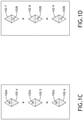
FIG. 1C is a view of an exemplary embodiment of air traffic indicators according to the inventive concepts disclosed herein. -
FIG. 1D is a view of an exemplary embodiment of air traffic indicators according to the inventive concepts disclosed herein. -
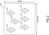
FIG. 2 is a view of an exemplary embodiment of a display image including air traffic indicators ofFIGS. 1A, 1B ,1C , and/or 1D according to the inventive concepts disclosed herein. -
FIG. 3 is a view of an exemplary embodiment of a system according to the inventive concepts disclosed herein. -
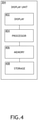
FIG. 4 is a view of an exemplary embodiment of a display unit computing device of the system ofFIG. 3 according to the inventive concepts disclosed herein. -
FIG. 5 is a view of an exemplary embodiment of an aircraft computing device of the system ofFIG. 3 according to the inventive concepts disclosed herein. -
FIG. 6 is a view of an exemplary embodiment of an ADS-B computing device of the system ofFIG. 3 according to the inventive concepts disclosed herein. -
FIG. 7 is a diagram of an exemplary embodiment of a method according to the inventive concepts disclosed herein. - Before explaining at least one embodiment of the inventive concepts disclosed herein in detail, it is to be understood that the inventive concepts are not limited in their application to the details of construction and the arrangement of the components or steps or methodologies set forth in the following description or illustrated in the drawings. In the following detailed description of embodiments of the instant inventive concepts, numerous specific details are set forth in order to provide a more thorough understanding of the inventive concepts. However, it will be apparent to one of ordinary skill in the art having the benefit of the instant disclosure that the inventive concepts disclosed herein may be practiced without these specific details. In other instances, well-known features may not be described in detail to avoid unnecessarily complicating the instant disclosure. The inventive concepts disclosed herein are capable of other embodiments or of being practiced or carried out in various ways. Also, it is to be understood that the phraseology and terminology employed herein is for the purpose of description and should not be regarded as limiting.
- As used herein a letter following a reference numeral is intended to reference an embodiment of the feature or element that may be similar, but not necessarily identical, to a previously described element or feature bearing the same reference numeral (e.g., 1, 1a, 1b). Such shorthand notations are used for purposes of convenience only, and should not be construed to limit the inventive concepts disclosed herein in any way unless expressly stated to the contrary.
- Further, unless expressly stated to the contrary, "or" refers to an inclusive or and not to an exclusive or. For example, a condition A or B is satisfied by anyone of the following: A is true (or present) and B is false (or not present), A is false (or not present) and B is true (or present), and both A and B are true (or present).
- In addition, use of the "a" or "an" are employed to describe elements and components of embodiments of the instant inventive concepts. This is done merely for convenience and to give a general sense of the inventive concepts, and "a" and "an" are intended to include one or at least one and the singular also includes the plural unless it is obvious that it is meant otherwise.
- Finally, as used herein any reference to "one embodiment," or "some embodiments" means that a particular element, feature, structure, or characteristic described in connection with the embodiment is included in at least one embodiment of the inventive concepts disclosed herein. The appearances of the phrase "in some embodiments" in various places in the specification are not necessarily all referring to the same embodiment, and embodiments of the inventive concepts disclosed may include one or more of the features expressly described or inherently present herein, or any combination of sub-combination of two or more such features, along with any other features which may not necessarily be expressly described or inherently present in the instant disclosure.
- Broadly, embodiments of the inventive concepts disclosed herein may be directed to a system (e.g., an aircraft system) and a method configured to display at least one air traffic indicator. Some embodiments may provide comprehensive graphics that declutter the display, which may be important in reducing pilot workload for single pilot operation. Some embodiments may simplify traffic avoidance while increasing operational efficiency and improving safety.
- Some embodiments may consolidate information of air traffic within a single air traffic indicator. For example, filling a top-half of the air traffic indicator with a top-half numerical value may indicate traffic above an ownship by an amount indicated by the top-half numerical value. For example, filling a bottom-half of the air traffic indicator with a bottom-half numerical value may indicate traffic below an ownship by an amount indicated by the bottom-half numerical value. Some embodiments may include a priority scheme where, if air traffic includes at least two aircraft that if depicted separately would have overlapping air traffic indicators, a combined air traffic indicator representing the at least two aircraft may be used. For example, if two aircraft are both above or both below, the combined air traffic indicator may indicate a numerical value for the vertically closest aircraft to the ownship due to greater proximity threat.
- Referring now to
FIGS. 1A, 1B ,1C, 1D , and2 exemplary embodiments of at least oneair traffic indicator 102 that may be depicted in adisplay image 200 are shown. Thedisplay image 200 may convey a range dimension and a horizontal dimension. Thedisplay image 200 may depict at least oneair traffic indicator 102. Each of the at least oneair traffic indicator 102 may be positioned (e.g., in the display image 200) respective to a corresponding range and horizontal location relative to a position of the aircraft (e.g., 302), wherein each of the at least one air traffic indicator indicates at least one of: an amount of a vertical distance of air traffic (e.g., an air traffic target) above the aircraft (e.g., 302), an amount of a vertical distance of air traffic (e.g., an air traffic target) below the aircraft (e.g., 302), or that air traffic (e.g., an air traffic target) has an approximately equal altitude as the aircraft (e.g., 302). - As shown in
FIG. 1A , three exemplaryair traffic indicators 102 are shown. Each of the threeair traffic indicators 102 may depict at least one numerical value (e.g., a top-halfnumerical value 102A, bottom-halfnumerical value 102B, and/or a zerovalue 102N). For example, a firstair traffic indicator 102 may have a top-halfnumerical value 102A positioned in a top half of the firstair traffic indicator 102, a secondair traffic indicator 102 may have a bottom-halfnumerical value 102B positioned in a bottom half of the secondair traffic indicator 102, and a thirdair traffic indicator 102 may have a zerovalue 102N. The top-halfnumerical value 102A may indicate the amount (e.g., "45" indicates air traffic is 4,500 feet above the aircraft) of the vertical distance of the air traffic (e.g., an air traffic target) above the aircraft (e.g., 302). The bottom-halfnumerical value 102B may indicate the amount (e.g., "25" indicates air traffic is 2,500 feet below the aircraft) of the vertical distance of the air traffic (e.g., an air traffic target) below the aircraft (e.g., 302). The zerovalue 102N may indicate that the air traffic (e.g., an air traffic target) has an approximately equal (e.g., 0 +/- 50 feet) altitude as the aircraft (e.g., 302). - Each
air traffic indicator 102 may have any suitable geometric shape (e.g., defined by at least one line and/or at least one curve; e.g., a diamond shape, as shown). - As shown in
FIGS. 1B ,1C, and 1D , someair traffic indicators 102 may be combined aircraft indicators (e.g., 102-3, 102-6, or 102-9). If air traffic includes at least two aircraft that if depicted separately would have overlapping air traffic indicators 102 (e.g., 102-1, 102-2, 102-4, 102-5, 102-7, and/or 102-8), a combined air traffic indicator (e.g., 102-3, 102-6, or 102-9) representing the at least two aircraft can be used to declutter thedisplay image 200. - As shown in
FIG. 1B , in some embodiments, rather than displaying air traffic indicators 102-1 (having a top-halfnumerical value 102A), 102-2 (having a bottom-halfnumerical value 102B) that would overlap (e.g., in the display image 200) based on the two air traffic targets having close horizontal and range location relative to the aircraft (e.g., 302), a combined air traffic indicator 102-3 representing the two air traffic targets can be used to declutter thedisplay image 200. The combined air traffic indicator 102-3 can include a top-halfnumerical value 102A and a bottom-halfnumerical value 102B. - As shown in
FIG. 1C , in some embodiments, rather than displaying air traffic indicators 102-4 (having a top-halfnumerical value 102A), 102-5 (having a top-halfnumerical value 102A) that would overlap (e.g., in the display image 200) based on the two air traffic targets having close horizontal and range location relative to the aircraft (e.g., 302), a combined air traffic indicator 102-6 representing the two air traffic targets can be used to declutter thedisplay image 200. The combined air traffic indicator 102-6 can include a top-halfnumerical value 102A for the air traffic target that is vertically closest to the aircraft (e.g., 302) as that is the closest threat to the aircraft (e.g., 302). - As shown in
FIG. 1D , in some embodiments, rather than displaying air traffic indicators 102-7 (having a bottom-halfnumerical value 102B), 102-8 (having a bottom-halfnumerical value 102B) that would overlap (e.g., in the display image 200) based on the two air traffic targets having close horizontal and range location relative to the aircraft (e.g., 302), a combined air traffic indicator 102-9 representing the two air traffic targets can be used to declutter thedisplay image 200. The combined air traffic indicator 102-9 can include a bottom-halfnumerical value 102B for the air traffic target that is vertically closest to the aircraft (e.g., 302) as that is the closest threat to the aircraft (e.g., 302). - As shown in
FIG. 2 , an exemplary embodiment of thedisplay image 200 depictingair traffic indicators 102 is shown. Thedisplay image 200 may convey a range dimension and a horizontal dimension. Thedisplay image 200 may depict at least oneair traffic indicator 102. Each of the at least oneair traffic indicator 102 may be positioned (e.g., in the display image 200) respective to a corresponding range and horizontal location relative to a position of the aircraft (e.g., 302). - Referring now to
FIGS. 3-6 , an exemplary embodiment of asystem 300 according to the inventive concepts disclosed herein is depicted. In some embodiments, the system may include anaircraft 302, which may include at least one user (e.g., flight crew and/or pilot(s)), at least one displayunit computing device 304, at least oneaircraft computing device 306, at least one automatic dependent surveillance-broadcast (ADS-B)computing device 308, and/or at least oneuser interface 310, some or all of which may be communicatively coupled at any given time. In some embodiments, the at least one displayunit computing device 304, the at least oneaircraft computing device 306, the at least one ADS-B computing device 308, and/or the at least oneuser interface 310 may be implemented as a single computing device or any number of computing devices configured to perform (e.g., collectively perform if more than one computing device) any or all of the operations disclosed throughout. The at least one displayunit computing device 304, the at least oneaircraft computing device 306, the at least one ADS-B computing device 308, and/or the at least oneuser interface 310 may be installed in theaircraft 302. - The user may be a pilot or crew member. The user may interface with the
system 300 via the at least oneuser interface 310. The at least oneuser interface 310 may be implemented as any suitable user interface, such as a touchscreen (e.g., of the displayunit computing device 304 and/or another display unit), a multipurpose control panel, a control panel integrated into a flight deck, a cursor control panel (CCP) (sometimes referred to as a display control panel (DCP)), a keyboard, a mouse, a trackpad, at least one hardware button, a switch, an eye tracking system, and/or a voice recognition system. Theuser interface 310 may be configured to receive at least one user input and to output the at least one user input to a computing device (e.g., 304, 306, and/or 308). For example, a pilot of the aircraft 104 may be able to interface with theuser interface 310 to: engage (or disengage) a mode to cause thedisplay image 200 to be displayed. For example, such user inputs may be output to the ADS-B computing device 308 and/or the displayunit computing device 304. - The display
unit computing device 304 may be implemented as any suitable computing device, such as a primary flight display (PFD) computing device and/or a multifunction window (MFW) display computing device. As shown inFIG. 4 , the displayunit computing device 304 may include at least onedisplay 402, at least oneprocessor 404, at least one memory 406, and/or at least one storage 410, some or all of which may be communicatively coupled at any given time. For example, the at least oneprocessor 404 may include at least one central processing unit (CPU), at least one graphics processing unit (GPU), at least one field-programmable gate array (FPGA), at least one application specific integrated circuit (ASIC), at least one digital signal processor, at least one virtual machine (VM) running on at least one processor, and/or the like configured to perform (e.g., collectively perform) any of the operations disclosed throughout. For example, the at least oneprocessor 404 may include a CPU and a GPU configured to perform (e.g., collectively perform) any of the operations disclosed throughout. Theprocessor 404 may be configured to run various software applications or computer code stored (e.g., maintained) in a non-transitory computer-readable medium (e.g., memory 406 and/or storage 410) and configured to execute various instructions or operations. Theprocessor 404 may be configured to perform any or all of the operations disclosed throughout. For example, theprocessor 404 may be configured to: obtain air traffic data (e.g., automatic dependent surveillance-broadcast (ADS-B) data from the ADS-B computing device 308) associated with air traffic; obtain aircraft data (e.g., from the computing device 306); generate adisplay image 200 based at least on the air traffic data and/or the aircraft data; and/or output thedisplay image 200 as graphical data. Thedisplay 402 may be configured to display thedisplay image 200 to a user. - The at least one
aircraft computing device 306 may be implemented as any suitable computing device, such as a flight management system (FMS) computing device or a flight data computer. The at least oneaircraft computing device 306 may include any or all of the elements, as shown inFIG. 5 . For example, theaircraft computing device 306 may include at least one processor 502, at least onememory 504, and/or at least one storage 506, some or all of which may be communicatively coupled at any given time. For example, the at least one processor 502 may include at least one central processing unit (CPU), at least one graphics processing unit (GPU), at least one field-programmable gate array (FPGA), at least one application specific integrated circuit (ASIC), at least one digital signal processor, at least one virtual machine (VM) running on at least one processor, and/or the like configured to perform (e.g., collectively perform) any of the operations disclosed throughout. For example, the at least one processor 502 may include a CPU and a GPU configured to perform (e.g., collectively perform) any of the operations disclosed throughout. The processor 502 may be configured to run various software applications (e.g., an FMS application) or computer code stored (e.g., maintained) in a non-transitory computer-readable medium (e.g.,memory 504 and/or storage 506) and configured to execute various instructions or operations. The processor 502 of theaircraft computing device 306 may be configured to perform any or all of the operations disclosed throughout. For example, the processor 502 of the computing device 210A may be configured to: output aircraft data (e.g., FMS data, flight path data, inertial reference unit (IRU) data, flight data, and/or flight computer data) to the displayunit computing device 304 and/or the ADS-B computing device 308. - The at least one ADS-
B computing device 308 may be implemented as any suitable computing device, such as an ADS-B receiver computing device. The at least one ADS-B computing device 308 may include any or all of the elements shown inFIG. 6 . For example, the ADS-B computing device 308 may include at least oneantenna 601, at least oneprocessor 602, at least one memory 604, and/or at least onestorage 606, some or all of which may be communicatively coupled at any given time. For example, the at least oneprocessor 602 may include at least one central processing unit (CPU), at least one graphics processing unit (GPU), at least one field-programmable gate array (FPGA), at least one application specific integrated circuit (ASIC), at least one digital signal processor, at least one virtual machine (VM) running on at least one processor, and/or the like configured to perform (e.g., collectively perform) any of the operations disclosed throughout. For example, the at least oneprocessor 602 may include a CPU and a GPU configured to perform (e.g., collectively perform) any of the operations disclosed throughout. Theprocessor 602 may be configured to run various software applications (e.g., an ADS-B application) or computer code stored (e.g., maintained) in a non-transitory computer-readable medium (e.g., memory 604 and/or storage 606) and configured to execute various instructions or operations. Theprocessor 602 of the ADS-B computing device 308 may be configured to perform any or all of the operations disclosed throughout. For example, theprocessor 602 may be configured to: obtain air traffic data; and/or output air traffic data to the displayunit computing device 304 and/or theaircraft computing device 306. - For example, at least one processor (e.g., the at least one
processor 404, the at least one processor 502, and/or the at least one processor 602) may be configured to (e.g., collectively configured to, if more than one processor): obtain air traffic data associated with air traffic; generate adisplay image 200 based at least on the air traffic data; and output thedisplay image 200 as graphical data. - At least one processor (e.g., the at least one
processor 404, the at least one processor 502, and/or the at least one processor 602) of theaircraft 302 may be configured to perform (e.g., collectively perform) any or all of the operations disclosed throughout. - Referring now to
FIG. 7 , an exemplary embodiment of amethod 700 according to the inventive concepts disclosed herein may include one or more of the following steps. Additionally, for example, some embodiments may include performing one or more instances of themethod 700 iteratively, concurrently, and/or sequentially. Additionally, for example, at least some of the steps of themethod 700 may be performed in parallel and/or concurrently. Additionally, in some embodiments, at least some of the steps of themethod 700 may be performed non-sequentially. - A
step 702 may include obtaining, by at least one processor installed in an aircraft and communicatively coupled to at least one display installed in the aircraft, air traffic data associated with air traffic. - A
step 704 may include generating, by the at least one processor, a display image based at least on the air traffic data. - A
step 706 may include outputting, by the at least one processor, the display image as graphical data. - A
step 708 may include displaying, by the at least one display, the display image to a user, wherein the display image conveys a range dimension and a horizontal dimension, wherein the display image depicts at least one air traffic indicator, each of the at least one air traffic indicator positioned respective to a corresponding range and horizontal location relative to the aircraft, wherein each of the at least one air traffic indicator indicates at least one of: an amount of a vertical distance of air traffic above the aircraft, an amount of a vertical distance of air traffic below the aircraft, or that air traffic has an approximately equal altitude as the aircraft. - Further, the
method 700 may include any of the operations disclosed throughout. - As will be appreciated from the above, embodiments of the inventive concepts disclosed herein may be directed to a system (e.g., an aircraft system) and a method configured to display at least one air traffic indicator.
- As used throughout and as would be appreciated by those skilled in the art, "at least one non-transitory computer-readable medium" may refer to as at least one non-transitory computer-readable medium (e.g., at least one computer-readable medium implemented as hardware; e.g., at least one non-transitory processor-readable medium, at least one memory (e.g., at least one nonvolatile memory, at least one volatile memory, or a combination thereof; e.g., at least one random-access memory, at least one flash memory, at least one read-only memory (ROM) (e.g., at least one electrically erasable programmable read-only memory (EEPROM)), at least one on-processor memory (e.g., at least one on-processor cache, at least one on-processor buffer, at least one on-processor flash memory, at least one on-processor EEPROM, or a combination thereof), or a combination thereof), at least one storage device (e.g., at least one hard-disk drive, at least one tape drive, at least one solid-state drive, at least one flash drive, at least one readable and/or writable disk of at least one optical drive configured to read from and/or write to the at least one readable and/or writable disk, or a combination thereof), or a combination thereof).
- As used throughout, "at least one" means one or a plurality of; for example, "at least one" may comprise one, two, three, ..., one hundred, or more. Similarly, as used throughout, "one or more" means one or a plurality of; for example, "one or more" may comprise one, two, three, ..., one hundred, or more. Further, as used throughout, "zero or more" means zero, one, or a plurality of; for example, "zero or more" may comprise zero, one, two, three, ..., one hundred, or more.
- In the present disclosure, the methods, operations, and/or functionality disclosed may be implemented as sets of instructions or software readable by a device. Further, it is understood that the specific order or hierarchy of steps in the methods, operations, and/or functionality disclosed are examples of exemplary approaches. Based upon design preferences, it is understood that the specific order or hierarchy of steps in the methods, operations, and/or functionality can be rearranged while remaining within the scope of the claims. The accompanying claims may present elements of the various steps in a sample order, and are not necessarily meant to be limited to the specific order or hierarchy presented.
- It is to be understood that embodiments of the methods according to the inventive concepts disclosed herein may include one or more of the steps described herein. Further, such steps may be carried out in any desired order and two or more of the steps may be carried out simultaneously with one another. Two or more of the steps disclosed herein may be combined in a single step, and in some embodiments, one or more of the steps may be carried out as two or more sub-steps. Further, other steps or sub-steps may be carried in addition to, or as substitutes to one or more of the steps disclosed herein.
- From the above description, it is clear that the inventive concepts disclosed herein are well adapted to carry out the objects and to attain the advantages mentioned herein as well as those inherent in the inventive concepts disclosed herein. While presently preferred embodiments of the inventive concepts disclosed herein have been described for purposes of this disclosure, it will be understood that numerous changes may be made which will readily suggest themselves to those skilled in the art and which are accomplished within the broad scope and coverage of the claims.
Claims (13)
- A system, comprising:at least one display (402) installed in an aircraft; andat least one processor (404) installed in the aircraft and communicatively coupled to the at least one display, the at least one processor configured to:obtain (702) air traffic data associated with air traffic;generate (704) a display image based at least on the air traffic data; andoutput (706) the display image as graphical data;wherein the at least one display is configured to display (708) the display image to a user;wherein the display image conveys a range dimension and a horizontal dimension, wherein the display image depicts at least one air traffic indicator, each of the at least one air traffic indicator positioned respective to a corresponding range and horizontal location relative to the aircraft, wherein each of the at least one air traffic indicator indicates at least one of: an amount of a vertical distance of air traffic above the aircraft, an amount of a vertical distance of air traffic below the aircraft, or that air traffic has an approximately equal altitude as the aircraft.
- The system of claim 1, wherein each of the at least one air traffic indicator depicts at least one numerical value, each of the at least one numerical value indicating the amount of the vertical distance of the air traffic above the aircraft, the amount of the vertical distance of the air traffic below the aircraft, or that the air traffic has the approximately equal altitude as the aircraft.
- The system of claim 2, wherein a top-half numerical value of the at least one numerical value positioned in a top half of one of the at least one air traffic indicator indicates the amount of the vertical distance of the air traffic above the aircraft.
- The system of claim 2 or 3, wherein a bottom-half numerical value of the at least one numerical value positioned in a bottom half of one of the at least one air traffic indicator indicates the amount of the vertical distance of the air traffic below the aircraft.
- The system of claim 2, 3, or 4, wherein a zero value of the at least one numerical value of the at least one air traffic indicator indicates that the air traffic has the approximately equal altitude as the aircraft.
- The system of any preceding claim, wherein each of the at least one air traffic indicator has a geometric shape.
- The system of claim 6, wherein the geometric shape is a diamond shape.
- The system of any preceding claim , wherein the air traffic includes at least two aircraft that if depicted separately would have overlapping air traffic indicators, wherein the at least one air traffic indicator includes a combined air traffic indicator representing the at least two aircraft.
- The system of claim 8, wherein at least two of the at least two aircraft are above the aircraft, wherein the combined air traffic indicator has a given top-half numerical value corresponding to one of the at least two of the at least two aircraft that is vertically closest to the aircraft.
- The system of claim 8 or 9, wherein at least two of the at least two aircraft are below the aircraft, wherein the combined air traffic indicator has a given bottom-half numerical value corresponding to one of the at least two of the at least two aircraft that is vertically closest to the aircraft.
- The system of claim 8, 9, or 10, wherein at least one of the at least two aircraft is below the aircraft, wherein at least one of the at least two aircraft is above the aircraft, wherein the combined air traffic indicator has a given bottom-half numerical value corresponding to one of the at least two aircraft below the aircraft that is vertically closest to the aircraft, wherein the combined air traffic indicator has a given top-half numerical value corresponding to one of the at least two aircraft above the aircraft that is vertically closest to the aircraft.
- The system of any preceding claim, wherein the air traffic data is automatic dependent surveillance-broadcast, ADS-B, data.
- A method (700), comprising:obtaining (702), by at least one processor (404) installed in an aircraft and communicatively coupled to at least one display (402) installed in the aircraft, air traffic data associated with air traffic;generating (704), by the at least one processor, a display image based at least on the air traffic data;outputting (706), by the at least one processor, the display image as graphical data; anddisplaying (708), by the at least one display, the display image to a user;wherein the display image conveys a range dimension and a horizontal dimension, wherein the display image depicts at least one air traffic indicator, each of the at least one air traffic indicator positioned respective to a corresponding range and horizontal location relative to the aircraft, wherein each of the at least one air traffic indicator indicates at least one of: an amount of a vertical distance of air traffic above the aircraft, an amount of a vertical distance of air traffic below the aircraft, or that air traffic has an approximately equal altitude as the aircraft.
Applications Claiming Priority (1)
| Application Number | Priority Date | Filing Date | Title |
|---|---|---|---|
| US17/028,425 US12080173B2 (en) | 2020-09-22 | 2020-09-22 | Aircraft system and method to display air traffic indicators |
Publications (2)
| Publication Number | Publication Date |
|---|---|
| EP3971868A1 true EP3971868A1 (en) | 2022-03-23 |
| EP3971868B1 EP3971868B1 (en) | 2026-03-25 |
Family
ID=77910591
Family Applications (1)
| Application Number | Title | Priority Date | Filing Date |
|---|---|---|---|
| EP21198318.4A Active EP3971868B1 (en) | 2020-09-22 | 2021-09-22 | Aircraft system and method to display air traffic indicators |
Country Status (2)
| Country | Link |
|---|---|
| US (1) | US12080173B2 (en) |
| EP (1) | EP3971868B1 (en) |
Families Citing this family (1)
| Publication number | Priority date | Publication date | Assignee | Title |
|---|---|---|---|---|
| US12555052B2 (en) * | 2022-01-19 | 2026-02-17 | Honeywell International Inc. | System for vehicle operator workload assessment and annunciation |
Citations (2)
| Publication number | Priority date | Publication date | Assignee | Title |
|---|---|---|---|---|
| EP2720215A1 (en) * | 2012-10-12 | 2014-04-16 | Honeywell International Inc. | System and method for increasing situational awareness by correlating intruder aircraft on a lateral map display and a vertical situation display |
| US20180315321A1 (en) * | 2017-04-26 | 2018-11-01 | Thales | Method of visualization of the traffic around of a reference aircraft in a non-compliant display zone, associated computer product program and visualization system |
Family Cites Families (20)
| Publication number | Priority date | Publication date | Assignee | Title |
|---|---|---|---|---|
| US3846746A (en) * | 1970-06-19 | 1974-11-05 | Technology Inc | Pilot warning indicator system |
| US6064335A (en) | 1997-07-21 | 2000-05-16 | Trimble Navigation Limited | GPS based augmented reality collision avoidance system |
| US6571177B1 (en) | 2000-09-18 | 2003-05-27 | Conoco Inc. | Color displays of multiple slices of 3-D seismic data |
| US6683562B2 (en) | 2001-07-20 | 2004-01-27 | Aviation Communications & Surveillance Systems, Llc | Integrated surveillance display |
| US7408552B2 (en) | 2002-02-08 | 2008-08-05 | Raytheon Company | System and method for representation of aircraft altitude using spatial size and other natural perceptual cues |
| US6927703B2 (en) | 2002-11-20 | 2005-08-09 | Honeywell International Inc. | Traffic awareness systems and methods for displaying aircraft traffic with ground-track heading |
| FR2854129B1 (en) | 2003-04-28 | 2007-06-01 | Airbus France | DISPLAY DEVICE IN AN AIRCRAFT COCKPIT WITH INFORMATION ABOUT SURROUNDING TRAFFIC |
| FR2921190B1 (en) | 2007-09-18 | 2010-08-27 | Thales Sa | DEVICE FOR PRESENTING AND SELECTING DATA ON A DISPLAY SCREEN |
| US8041504B2 (en) | 2007-12-17 | 2011-10-18 | The Boeing Company | Method and system for display of guidance reference for traffic situational awareness |
| FR2935825B1 (en) | 2008-09-09 | 2010-09-24 | Thales Sa | VISUALIZATION DEVICE FOR AIRCRAFT COMPRISING DISPLAY MEANS FOR INTRUS TRAJECTORIES HAVING COLLISION RISK IN THE ENTIRE AIRCRAFT SURROUNDING AREA |
| US8160755B2 (en) | 2008-09-30 | 2012-04-17 | Honeywell International Inc. | Displaying air traffic symbology based on relative importance |
| US8514102B2 (en) | 2010-01-14 | 2013-08-20 | Honeywell International Inc. | Aircraft navigation accuracy display system |
| US8736465B2 (en) | 2011-01-17 | 2014-05-27 | L-3 Communications Avionics Systems, Inc. | Aircraft traffic display |
| US8773288B1 (en) | 2011-09-20 | 2014-07-08 | Rockwell Collins, Inc. | Methods for presenting traffic information on an aircraft display unit |
| US9105183B2 (en) | 2013-06-17 | 2015-08-11 | Honeywell International Inc. | System and method for graphically displaying aircraft traffic information using aircraft symbology |
| US9401091B2 (en) | 2013-09-13 | 2016-07-26 | Honeywell International Inc. | System and method for displaying In-Trail Procedure (ITP) allocations on an aircraft cockpit display |
| US9142133B2 (en) | 2013-10-29 | 2015-09-22 | Honeywell International Inc. | System and method for maintaining aircraft separation based on distance or time |
| US9718558B2 (en) | 2014-02-26 | 2017-08-01 | Honeywell International Inc. | Pilot centered system and method for decluttering aircraft displays |
| US9501936B2 (en) | 2014-09-02 | 2016-11-22 | Honeywell International Inc. | Aircraft systems and methods for displaying spacing information |
| US20200020239A1 (en) | 2018-07-13 | 2020-01-16 | Honeywell International Inc. | Characteristics of graphical icons for presentation of traffic information |
-
2020
- 2020-09-22 US US17/028,425 patent/US12080173B2/en active Active
-
2021
- 2021-09-22 EP EP21198318.4A patent/EP3971868B1/en active Active
Patent Citations (2)
| Publication number | Priority date | Publication date | Assignee | Title |
|---|---|---|---|---|
| EP2720215A1 (en) * | 2012-10-12 | 2014-04-16 | Honeywell International Inc. | System and method for increasing situational awareness by correlating intruder aircraft on a lateral map display and a vertical situation display |
| US20180315321A1 (en) * | 2017-04-26 | 2018-11-01 | Thales | Method of visualization of the traffic around of a reference aircraft in a non-compliant display zone, associated computer product program and visualization system |
Also Published As
| Publication number | Publication date |
|---|---|
| EP3971868B1 (en) | 2026-03-25 |
| US20220092991A1 (en) | 2022-03-24 |
| US12080173B2 (en) | 2024-09-03 |
Similar Documents
| Publication | Publication Date | Title |
|---|---|---|
| US20250054399A1 (en) | System and method to display view of airport moving map depicting runway overrun awareness and alerting system (roaas)-based indicators | |
| US9501936B2 (en) | Aircraft systems and methods for displaying spacing information | |
| CN102682625B (en) | For providing the system and method for ITP clearance information | |
| US11501647B2 (en) | Estimated wake turbulence trail for aircraft system | |
| US10971020B1 (en) | Aircraft system and method to provide linear map of traffic | |
| CN104925267A (en) | System And Method For Displaying Vertical Reference On A Rotorcraft System | |
| EP3971868B1 (en) | Aircraft system and method to display air traffic indicators | |
| US11347463B2 (en) | Correlative display system with decluttered displays for aircraft | |
| EP3734573B1 (en) | Flight interval management graphical speed performance monitor | |
| EP4155772A1 (en) | System and method to select and display prioritized azimuth slice vertical radar image | |
| US11543520B2 (en) | Aircraft system and method to display three-dimensional threat image | |
| EP4180769A1 (en) | System and method for providing more readable font characters in size adjusting avionics charts | |
| EP3920162A1 (en) | Aircraft system and method to provide graphical threshold indicator | |
| US11500474B2 (en) | Aircraft system and method to move cursor to default position with hardware button | |
| EP4166906A2 (en) | Air traffic depiction for portable and installed aircraft displays | |
| EP4134706A1 (en) | System and method to display aircraft relative storm top image | |
| US11769417B2 (en) | Methods and systems for representing flight mode annunciation information on a cockpit display | |
| EP4016005B1 (en) | System and method to display svs taxi mode exocentric view of aircraft | |
| EP4210024A1 (en) | Systems and methods for enabling user control over use of aircraft sensors located onboard an aircraft | |
| EP4166985A1 (en) | System and method to adjust or suppress windshear alert threshold for weather radar | |
| US20230177965A1 (en) | Automatic selection of best air data source for aircraft | |
| EP4180772A1 (en) | Electronic chart application with enhanced element searching and highlighting using generic third-party data | |
| US20200342773A1 (en) | Method and electronic device for managing the display of an aircraft flight profile with selection of suitable resolution(s) of field data base(s), related computer program and electronic display system |
Legal Events
| Date | Code | Title | Description |
|---|---|---|---|
| PUAI | Public reference made under article 153(3) epc to a published international application that has entered the european phase |
Free format text: ORIGINAL CODE: 0009012 |
|
| STAA | Information on the status of an ep patent application or granted ep patent |
Free format text: STATUS: THE APPLICATION HAS BEEN PUBLISHED |
|
| AK | Designated contracting states |
Kind code of ref document: A1 Designated state(s): AL AT BE BG CH CY CZ DE DK EE ES FI FR GB GR HR HU IE IS IT LI LT LU LV MC MK MT NL NO PL PT RO RS SE SI SK SM TR |
|
| STAA | Information on the status of an ep patent application or granted ep patent |
Free format text: STATUS: REQUEST FOR EXAMINATION WAS MADE |
|
| 17P | Request for examination filed |
Effective date: 20220923 |
|
| RBV | Designated contracting states (corrected) |
Designated state(s): AL AT BE BG CH CY CZ DE DK EE ES FI FR GB GR HR HU IE IS IT LI LT LU LV MC MK MT NL NO PL PT RO RS SE SI SK SM TR |
|
| STAA | Information on the status of an ep patent application or granted ep patent |
Free format text: STATUS: EXAMINATION IS IN PROGRESS |
|
| 17Q | First examination report despatched |
Effective date: 20250219 |
|
| REG | Reference to a national code |
Ref country code: DE Ref legal event code: R079 Free format text: PREVIOUS MAIN CLASS: G08G0005000000 Ipc: G08G0005210000 Ref country code: DE Ref legal event code: R079 Ref document number: 602021050509 Country of ref document: DE Free format text: PREVIOUS MAIN CLASS: G08G0005000000 Ipc: G08G0005210000 |
|
| GRAP | Despatch of communication of intention to grant a patent |
Free format text: ORIGINAL CODE: EPIDOSNIGR1 |
|
| STAA | Information on the status of an ep patent application or granted ep patent |
Free format text: STATUS: GRANT OF PATENT IS INTENDED |
|
| RIC1 | Information provided on ipc code assigned before grant |
Ipc: G08G 5/21 20250101AFI20251124BHEP Ipc: G08G 5/72 20250101ALI20251124BHEP Ipc: G08G 5/80 20250101ALI20251124BHEP |
|
| INTG | Intention to grant announced |
Effective date: 20251218 |
|
| GRAS | Grant fee paid |
Free format text: ORIGINAL CODE: EPIDOSNIGR3 |
|
| GRAA | (expected) grant |
Free format text: ORIGINAL CODE: 0009210 |
|
| STAA | Information on the status of an ep patent application or granted ep patent |
Free format text: STATUS: THE PATENT HAS BEEN GRANTED |
|
| AK | Designated contracting states |
Kind code of ref document: B1 Designated state(s): AL AT BE BG CH CY CZ DE DK EE ES FI FR GB GR HR HU IE IS IT LI LT LU LV MC MK MT NL NO PL PT RO RS SE SI SK SM TR |
|
| REG | Reference to a national code |
Ref country code: CH Ref legal event code: F10 Free format text: ST27 STATUS EVENT CODE: U-0-0-F10-F00 (AS PROVIDED BY THE NATIONAL OFFICE) Effective date: 20260325 Ref country code: GB Ref legal event code: FG4D |
|
| REG | Reference to a national code |
Ref country code: DE Ref legal event code: R096 Ref document number: 602021050509 Country of ref document: DE |
|
| REG | Reference to a national code |
Ref country code: IE Ref legal event code: FG4D |