EP3971826A1 - Image comparison apparatus - Google Patents
Image comparison apparatus Download PDFInfo
- Publication number
- EP3971826A1 EP3971826A1 EP19928843.2A EP19928843A EP3971826A1 EP 3971826 A1 EP3971826 A1 EP 3971826A1 EP 19928843 A EP19928843 A EP 19928843A EP 3971826 A1 EP3971826 A1 EP 3971826A1
- Authority
- EP
- European Patent Office
- Prior art keywords
- image
- frequency feature
- quantized
- value
- unit
- Prior art date
- Legal status (The legal status is an assumption and is not a legal conclusion. Google has not performed a legal analysis and makes no representation as to the accuracy of the status listed.)
- Granted
Links
Images











Classifications
-
- G—PHYSICS
- G06—COMPUTING OR CALCULATING; COUNTING
- G06V—IMAGE OR VIDEO RECOGNITION OR UNDERSTANDING
- G06V10/00—Arrangements for image or video recognition or understanding
- G06V10/40—Extraction of image or video features
- G06V10/42—Global feature extraction by analysis of the whole pattern, e.g. using frequency domain transformations or autocorrelation
- G06V10/431—Frequency domain transformation; Autocorrelation
-
- G—PHYSICS
- G06—COMPUTING OR CALCULATING; COUNTING
- G06V—IMAGE OR VIDEO RECOGNITION OR UNDERSTANDING
- G06V10/00—Arrangements for image or video recognition or understanding
- G06V10/70—Arrangements for image or video recognition or understanding using pattern recognition or machine learning
- G06V10/74—Image or video pattern matching; Proximity measures in feature spaces
- G06V10/75—Organisation of the matching processes, e.g. simultaneous or sequential comparisons of image or video features; Coarse-fine approaches, e.g. multi-scale approaches; using context analysis; Selection of dictionaries
- G06V10/753—Transform-based matching, e.g. Hough transform
-
- G—PHYSICS
- G06—COMPUTING OR CALCULATING; COUNTING
- G06T—IMAGE DATA PROCESSING OR GENERATION, IN GENERAL
- G06T3/00—Geometric image transformations in the plane of the image
- G06T3/10—Selection of transformation methods according to the characteristics of the input images
-
- G—PHYSICS
- G06—COMPUTING OR CALCULATING; COUNTING
- G06T—IMAGE DATA PROCESSING OR GENERATION, IN GENERAL
- G06T7/00—Image analysis
- G06T7/10—Segmentation; Edge detection
- G06T7/11—Region-based segmentation
-
- G—PHYSICS
- G06—COMPUTING OR CALCULATING; COUNTING
- G06V—IMAGE OR VIDEO RECOGNITION OR UNDERSTANDING
- G06V10/00—Arrangements for image or video recognition or understanding
- G06V10/40—Extraction of image or video features
-
- G—PHYSICS
- G06—COMPUTING OR CALCULATING; COUNTING
- G06V—IMAGE OR VIDEO RECOGNITION OR UNDERSTANDING
- G06V10/00—Arrangements for image or video recognition or understanding
- G06V10/70—Arrangements for image or video recognition or understanding using pattern recognition or machine learning
- G06V10/74—Image or video pattern matching; Proximity measures in feature spaces
- G06V10/761—Proximity, similarity or dissimilarity measures
-
- G—PHYSICS
- G06—COMPUTING OR CALCULATING; COUNTING
- G06T—IMAGE DATA PROCESSING OR GENERATION, IN GENERAL
- G06T2207/00—Indexing scheme for image analysis or image enhancement
- G06T2207/20—Special algorithmic details
- G06T2207/20021—Dividing image into blocks, subimages or windows
Definitions
- the present invention relates to an image matching apparatus, an image matching method, and a program.
- Patent Document 1 first, a compared image and a registered image are transformed into the frequency domain by using the Fourier transform. Next, a cross power spectrum is calculated from the respective complex spectra of the compared image and the registered image obtained by the above transformation. Next, the cross power spectrum is normalized to phase components alone by eliminating power components using a weight filter for each frequency. Next, a correlation efficient on a real coordinate domain is calculated by applying the inverse Fourier transform to the normalized cross power spectrum. Next, pattern matching determination is performed by using coordinates that make the calculated correlation coefficient the maximum value.
- a registered Fourier image is created in advance by applying the Fourier transform to a registered image.
- a compared Fourier image is created by applying the Fourier transform to a compared image.
- the compared Fourier image and the registered Fourier image created in advance are synthesized.
- an amplitude suppression process is performed on the above synthesized Fourier image and then the inverse Fourier transform is applied.
- the upper n pixels with correlation components having higher intensity are extracted from a predetermined correlation component area appearing in the synthetized Fourier image with the inverse Fourier transform applied. Then, based on the intensity of the correlation components of the extracted n pixels, it is determined whether or not the registered image and the compared image match.
- Non-Patent Document 1 by obtaining a normalized cross power spectrum that is a synthesized frequency feature obtained by synthesizing the frequency feature of a registered image and the frequency feature of a compared image, and determining a distribution shape in the frequency feature, the compared image is matched against the registered image.
- Non-Patent Document 1 focuses on that in the case of a pair of identical images with a position gap, a normalized cross power spectrum of the frequency features of the two images becomes a complex sine wave having a single period with respect to a discrete frequency index.
- Non-Patent Document 1 by calculation of the partial differential of the normalized cross power spectrum, calculation of the absolute values of the elements with respect to the obtained differential result, and calculation of the variance of the obtained absolute values, a score indicating a degree that the normalized cross power spectrum of the frequency features of the two images is a complex sine wave having a single period is calculated, and the two images are matched against each other based on the score.
- Non-Patent Document 1 Toru Takahashi, Kengo Makino, Yuta Kudo, Rui Ishiyama, "A Study of Fast Image Matching Method Under Translation, Scale, and Rotation", IEICE Technical Report, BioX2017-42, PRMU2017-178 , March 2018
- Patent Document 1 and Patent Document 2 in the case of matching two images against each other, it is general to use the result of synthesizing the frequency features of the two images and applying the inverse Fourier transform to the synthesized frequency feature.
- the complexity of the inverse Fourier transform is large. Therefore, it is difficult to match two images against each other at high speeds.
- the inverse Fourier transform is not required, and the matching score can be calculated by lighter operations.
- the complexity required to calculate the matching score is still large. The reason is as follows. In order to calculate a score indicating a degree that the normalized cross power spectrum of the frequency features of two images is a complex sine wave having a single period, there is a need to obtain the normalized cross power spectrum as a complex sine wave while minimizing an error. For this, many bits need to be allocated to represent the elements of the normalized cross power spectrum.
- An object of the present invention is to provide an image matching apparatus that solves the abovementioned problem; it is difficult to match two images against each other at high speeds.
- An image matching apparatus is an image matching apparatus matching a first image against a second image.
- the image matching apparatus includes: an acquiring unit configured to acquire a frequency feature of the first image and a frequency feature of the second image; a generating unit configured to synthesize the frequency feature of the first image and the frequency feature of the second image, and generate a quantized synthesized frequency feature in which a value of an element is represented by a binary value or a ternary value; and a determining unit configured to calculate a score indicating a degree to which the quantized synthesized frequency feature is a square wave having a single period, and match the first image against the second image based on the score.
- an image matching method is an image matching method for matching a first image against a second image.
- the image matching method includes: acquiring a frequency feature of the first image and a frequency feature of the second image; synthesizing the frequency feature of the first image and the frequency feature of the second image, and generating a quantized synthesized frequency feature in which a value of an element is represented by a binary value or a ternary value; and calculating a score indicating a degree to which the quantized synthesized frequency feature is a square wave having a single period, and matching the first image against the second image based on the score.
- a non-transitory computer-readable recording medium has a program recorded thereon.
- the program includes instructions for causing a computer matching a first image against a second image to execute: a process of acquiring a frequency feature of the first image and a frequency feature of the second image; a process of synthesizing the frequency feature of the first image and the frequency feature of the second image, and generating a quantized synthesized frequency feature in which a value of an element is represented by a binary value or a ternary value; and a process of calculating a score indicating a degree to which the quantized synthesized frequency feature is a square wave having a single period, and matching the first image against the second image based on the score.
- the present invention enables high-speed matching of a first image and a second image.
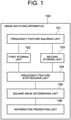
- Fig. 1 is a block diagram of an image matching apparatus according to a first example embodiment of the present invention.
- An image matching apparatus 100 according to this example embodiment is configured to match a first image against a second image.
- the image matching apparatus 100 includes a frequency feature acquiring unit 101, a first storing unit 102, a second storing unit 103, a frequency feature synthesizing unit 104, a square wave determining unit 105, and an information presenting unit 106.
- the frequency feature acquiring unit 101 is configured to acquire the frequency features of a first image and a second image.
- a frequency feature refers to two-dimensional data (two-dimensional array) as a result of applying the Fourier transform (discrete Fourier transform) to an image and thereby transforming into the frequency domain.
- Frequency transform other than the Fourier transform, for example, Wavelet transform may be performed.
- a first image is, for example, a compared image obtained by imaging an object to be compared.
- a second image is one of a plurality of registered images obtained by imaging a plurality of objects to be registered.
- One or a plurality of second images are present.
- An object is, for example, an industrial product, a commercial product, or the like.
- On the surface of an object there is a fine pattern that naturally occurs in the same production process such as fine irregularities or patterns or a random pattern on the material surface.
- an imaging device such as a camera and recognizing the fine pattern, it is possible to perform individual identification and management of each product.
- This example embodiment relates to an image matching technique for such individual identification.
- the first storing unit 102 is configured to store the frequency feature of the first image.
- the second storing unit 103 is configured to store the frequency feature of the second image.
- the frequency feature synthesizing unit 104 is configured to synthesize the frequency feature of the first image stored in the first storing unit 102 and the frequency feature of the second image stored in the second storing unit 103, and calculate a normalized cross power spectrum in which the values of elements are represented by binary or ternary values (hereinafter, referred to as a quantized cross power spectrum).
- the square wave determining unit 105 is configured to calculate a score indicating a degree that the quantized cross power spectrum calculated by the frequency feature synthesizing unit 104 is a square wave signal having a single period. Moreover, the square wave determining unit 105 is configured to match the first image against the second image based on the calculated score. That is to say, the square wave determining unit 105 uses a score indicating a degree that a quantized cross power spectrum quantized into binary or ternary values is a square wave signal having a single period, as a score representing the degree of similarity between the first image and the second image.
- the information presenting unit 106 is configured to present the result of matching of the first image and the second image based on the result of determination by the square wave determining unit 105.
- the presentation of the matching result may be, for example, displaying the matching result on a display device, or printing the matching result on a sheet of paper by a printing device, or transmitting a message describing the matching result to an external terminal by a communication device.
- the image matching apparatus 100 can be realized by an information processing device 200 that includes an imaging unit 201 such as a camera, an operation input unit 202 such as a keyboard and a mouse, a screen display unit 203 such as a liquid crystal display, a communication interface unit 204, a storing unit 205 such as a memory and a hard disk and an arithmetic processing unit 206 such as one or more microprocessors, and a program 207.
- the information processing device 200 may be, for example, a personal computer or a smartphone.
- the program 207 is loaded into a memory from an external computer-readable storage medium when the information processing device 200 is started, and controls an operation of the arithmetic processing unit 206 to realize on the arithmetic processing unit 206 functional units such as the frequency feature acquiring unit 101, the first storing unit 102, the second storing unit 103, the frequency feature synthesizing unit 104, the square wave determining unit 105, and the information presenting unit 106.
- Fig. 3 is a flowchart showing the outline of the operation of the image matching apparatus 100.
- the frequency feature acquiring unit 101 acquires the frequency feature of the first image and the frequency feature of the second image (step S1). In a case where a plurality of second images are present, the frequency feature acquiring unit 101 acquires a frequency feature from each of the second images.
- the frequency feature acquiring unit 101 stores the acquired frequency feature of the first image into the first storing unit 102, and stores the acquired frequency feature of the second image into the second storing unit 103.
- the frequency feature synthesizing unit 104 calculates a normalized cross power spectrum of the frequency feature of the first image stored in the first storing unit 102 and the frequency feature of the second image stored in the second storing unit 103 (step S2). In a case where there are a plurality of frequency features of second images, the frequency feature synthesizing unit 104 calculates a plurality of normalized cross power spectra of the frequency feature of the first image and the respective frequency features of the second images. Moreover, the frequency feature synthesizing unit 104 quantizes the calculated normalized cross power spectrum, and transforms the value of each of the elements to binary or ternary data (step S3). In a case where there are a plurality of normalized cross power spectra, the frequency feature synthesizing unit 104 quantizes the respective normalized cross power spectra.
- the square wave determining unit 105 calculates a score indicating a degree that the quantized cross power spectrum obtained from the frequency feature synthesizing unit 104 is a square wave having a single period (step S4).
- the square wave determining unit 105 calculates, for each of the quantized cross power spectra, a score indicating a degree that it is a square wave having a single period.
- the square wave determining unit 105 matches the first image against the second image based on the calculated score (step S5).
- the square wave determining unit 105 derives a matching result indicating that the first image and the second image match (identical) when the score satisfies a predetermined reference value.
- the square wave determining unit 105 derives a matching result indicating that the first image and the second image do not match (not identical).
- the square wave determining unit 105 when a best score among a plurality of scores calculated for a plurality of cross power spectra corresponding to the plurality of second images satisfies a predetermined reference value, the square wave determining unit 105 derives a matching result indicating that the first image and the second image of the best score match (identical). On the other hand, when the best score does not satisfy the predetermined reference value, the square wave determining unit 105 derives a matching result indicating that the first image and the second image do not match (not identical).
- the information presenting unit 106 presents the result of matching of the first image and the second image obtained from the square wave determining unit 105.
- Fig. 4 is a block diagram showing an example of the frequency feature acquiring unit 101.
- the frequency feature acquiring unit 101 in this example includes an image acquiring unit 111 and a frequency transform unit 112.
- the image acquiring unit 111 is configured to acquire the first image and the second image.
- the image acquiring unit 111 may be, for example, image capture equipment typified by a camera, a scanner, and the like.
- the image acquiring unit 111 may be an optical sensor that collects visible light and light having a wavelength longer than visible light such as near-infrared light, short-wavelength infrared light and thermal infrared light with a lens and acquires the shape of a target object, or the like, as image data.
- the image acquiring unit 111 may be a sensor that acquires the intensity of infrared light, ultraviolet light or X-ray and outputs as a two-dimensional data array.
- the image acquiring unit 111 may be configured to acquire the first image and the second image from an external storage medium such as a CD-ROM or a memory.
- the image acquiring unit 111 may be configured to receive the first image and the second image via a network.
- the image acquiring unit 111 may acquire the first image and the second image by different methods, respectively.
- the frequency transform unit 112 is configured to receive the first image and the second image from the image acquiring unit 111, and output an image (a frequency spectrum image) as a result of applying discrete Fourier transform to each of the images.
- the frequency transform unit 112 stores the frequency spectrum image of the first image as a first frequency feature into the first storing unit 102, and stores the frequency spectrum of the second image as a second frequency feature into the second storing unit 103.
- the first image and the second image be two images f(n 1 , n 2 ) and g(n 1 , n 2 ) of N 1 ⁇ N 2 pixels.
- M 1 and M 2 are positive integers
- Equations 1 and 2 a first frequency feature F(k 1 , k 2 ) obtained by applying two-dimensional discrete Fourier transform to the image f(n 1 , n 2 ) and a second frequency feature G(k 1 , k 2 ) obtained by applying two-dimensional discrete Fourier transform to the image g(n 1 ,n 2 ) are given by Equations 1 and 2 shown in Fig. 5 .
- W N1 and W N2 are twiddle factors, which are given by Equations 3 and 4 shown in Fig. 5 .
- a F (k 1 , k 2 ) and A G (k 1 , k 2 ) represent amplitude spectra (amplitude components), and ⁇ F (k 1 , k 2 ) and ⁇ G (k 1 , k 2 ) represent phase spectra (phase components), respectively.
- ⁇ n1,n2 represents addition over the entire index range as shown in Equation 5 of Fig. 5 .
- Fig. 6 shows an example of the image of the amplitude components A F (k 1 , k 2 ) and A G (k 1 , k 2 ) and the phase components ⁇ F (k 1 , k 2 ) and ⁇ G (k 1 , k 2 ).
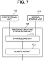
- Fig. 7 is a block diagram showing an example of the frequency feature synthesizing unit 104.
- the frequency feature synthesizing unit 104 in this example includes a synthesizing unit 121 and a quantizing unit 122.
- the synthesizing unit 121 calculates a normalized cross power spectrum R(k 1 , k 2 ) of the first frequency feature F(k 1 , k 2 ) and the second frequency feature G(k 1 , k 2 ) by Equation 6 shown in Fig. 8 .
- overline G(k 1 , k 2 ) is a complex conjugate of the second frequency feature G(k 1 , k 2 ).
- ⁇ F (k 1 , k 2 )- ⁇ G (k 1 , k 2 ) is a phase difference spectrum of the first frequency feature and the second frequency feature.
- the frequency feature synthesizing unit 104 obtains a cross power spectrum that is the product for each element of the first frequency feature F(k 1 , k 2 ) and the complex conjugate of the second frequency feature G(k 1 , k 2 ) and normalizes with the absolute value thereof, thereby calculating the normalized cross power spectrum.
- the frequency feature F(k 1 , k 2 ) and the frequency feature G(k 1 , k 2 ) of the images, and the normalized cross power spectrum R(k 1 , k 2 ) of the two frequency features are given by Equations 7, 8 and 9 shown in Fig 9 .
- ⁇ 1 and ⁇ 2 denote the amount of position gap between the image f(n 1 , n 2 ) and the image g(n 1 , n 2 ).
- the image g(n 1 , n 2 ) is an image obtained by translating the image f(n 1 , n 2 ) by ( ⁇ 1 , ⁇ 2 ).
- the normalized cross power spectrum R(k 1 , k 2 ) thereof is expressed as a complex sine wave having a single period for each of the dimensions (each of k 1 and k 2 ).
- the normalized cross power spectrum R(k 1 , k 2 ) is not a complex sine wave having a single period for each of the dimensions.
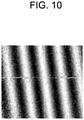
- Fig. 10 shows an example of the image of the normalized cross power spectrum R (k 1 , k 2 ) of a pair of identical images.
- a normalized cross power spectrum of a pair of identical images has an image like a wave having a single period when a bright portion is regarded as a peak and a dark portion is regarded as a trough.
- the quantizing unit 122 quantizes each element of the normalized cross power spectrum obtained by the synthesizing unit 121 into binary or ternary data.
- a method for such quantization can be any method. For example, a quantization method as described below may be used.
- the quantizing unit 122 substitutes a value (composed of a real part and an imaginary part) of each element of the normalized cross power spectrum obtained by the synthesizing unit 121 with a value obtained by quantizing a predetermined one of the real part and the imaginary part of each element to a binary or ternary value.
- a value obtained by quantizing a predetermined one of the real part and the imaginary part of each element to a binary or ternary value.
- the value of a certain element U be A+Bj.
- a and B are real numbers
- j is an imaginary unit.
- the quantizing unit 122 transforms A+Bj to "+1" if A ⁇ 0, and transforms A+Bj to "-1" if A ⁇ 0, for example.
- the quantizing unit 122 quantizes into a binary value based on the sign of the real number A of the real part, but may quantize into a binary value based on the sign of the real number B of the imaginary part.
- the quantizing unit 122 quantizes into a binary value based on the sign of the real number A of the real part, but may quantize into a binary value based on the sign of the real number B of the imaginary part.
- the quantizing unit 122 represents each element of the normalized cross power spectrum obtained by the synthesizing unit 121 as 1-bit or 2-bit data.
- the reason that the quantizing unit 122 quantizes each element of the normalized cross power spectrum into binary or ternary data is as follows.
- a real part and an imaginary part of each element of the normalized cross power spectrum R are calculated as real number values (floating point numbers), and many bits are required to represent each element (for example, 64-bit data for double precision floating point numbers, and 32-bit data for single precision floating point numbers).
- a normalized cross power spectrum as a complex sine wave with as little error as possible and obtain the period of the complex sine wave with accuracy.
- the quantizing unit 122 quantizes each element of a normalized cross power spectrum obtained by the synthesizing unit 121 into binary or ternary data.
- Fig. 11 shows an example of an image in which the normalized cross power spectrum R(k 1 , k 2 ) of a pair of identical images is quantized into binary data.
- the pattern of a wave having a single period in which a light portion is regarded as a peak and a dark portion is regarded as a trough can be kept. Therefore, even if a normalized cross power spectrum that is real number data represented by 32-bit or 64-bit conventionally is quantized into binary (1-bit) or ternary (2-bit) data to reduce the amount of data, it is possible to determine the presence or absence of a correlation between input images without lowering accuracy. That is to say, it is possible to realize distinguishing a pair of identical images having a correlation from a pair of different images having no correlation with less data amount without impairing accuracy.
- the square wave determining unit 105 quantifies a degree that a normalized cross power spectrum with elements quantized into binary or ternary values calculated by the frequency feature synthesizing unit 104 is a square wave having a single period, and outputs as a score.
- Fig. 12 is a block diagram showing an example of the square wave determining unit 105.
- the square wave determining unit 105 in this example includes, for example, an orthogonal transformation unit 131 that performs orthogonal transformation using a Hadamard matrix.
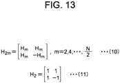
- a Hadamard matrix is a square matrix whose elements are "+1" and "-1" and whose rows are mutually orthogonal.
- the Hadamard matrix H m is defined as Equations 10 and 11 of Fig. 13 .
- the orthogonal transformation unit 131 is configured to perform orthogonal transformation using a Hadamard matrix on a normalized cross power spectrum quantized into binary or ternary values and output the maximum value of the output as a score.
- the quantized normalized cross power spectrum is a square wave having a single period
- a sharp peak value of the period appears in the output by the orthogonal transformation unit 131.
- the quantized normalized cross power spectrum is not a square wave having a single period, a sharp peak value does not appear in the output by the orthogonal transformation unit 131.
- the maximum value of the output by the orthogonal transformation unit 131 can be a score indicating a degree that the quantized normalized cross power spectrum is a square wave having a single period.
- the orthogonal transformation unit 131 matches images against each other based on the calculated score.
- Equation 12 The orthogonal transformation using the Hadamard matrix performed by the orthogonal transformation unit 131 is described by Equation 12 of Fig. 14 .
- H N denotes a Hadamard matrix
- X denotes an N ⁇ N input signal (quantized cross power spectrum)
- Y denotes an N ⁇ N output signal (score).
- the operation of Equation 12 can be executed by logical operation such as exclusive OR (XOR), bit counting, and a combination of addition and subtraction, so that high-speed processing is possible.
- Equation 12 can be executed by logical operation such as exclusive OR (XOR), bit counting, and a combination of addition and subtraction on the elements "+1" and “-1” without executing the operation on the elements having a value of "0", so that high-speed processing is possible.
- logical operation such as exclusive OR (XOR), bit counting, and a combination of addition and subtraction on the elements "+1” and “-1” without executing the operation on the elements having a value of "0", so that high-speed processing is possible.
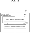
- Fig. 15 is a block diagram showing another example of the square wave determining unit 105.
- the square wave determining unit 105 of this example includes a circular shift processing unit 141 and a similarity degree calculating unit 142.
- the circular shift processing unit 141 is configured to input a normalized cross power spectrum with elements quantized into binary or ternary values (hereinafter referred to as data before circular shift) and output a quantized cross power spectrum with the elements circularly shifted by a rotate no carry operation or the like (hereinafter referred to as data after circular shift). Moreover, the circular shift processing unit 141 is configured to variously change a circular shift amount and thereby output a plurality of data after circular shift having different circular shift amounts.
- the similarity degree calculating unit 142 is configured to input data before circular shift and a plurality of data after circular shift with different circular shift amounts, and calculate a plurality of similarity degrees between the data before circular shift and the plurality of data after circular shift. Moreover, the similarity degree calculating unit 142 is configured to output the maximum similarity degree among the calculated similarity degrees as a score. The similarity degree calculating unit 142 performs image matching based on the calculated score.
- the data before circular shift is a square wave having a single period
- the circular shift processing unit 141 circularly shifts the data before circular shift
- a square wave having the same single period as the data before circular shift periodically appears as the data after circular shift.
- the data before circular shift is not a square wave having a single period
- the circular shift processing unit 141 circularly shifts the data before circular shift with various shift amounts, data after circular shift having the same pattern as the data before circular shift does not appear.
- the abovementioned circular shift processing unit 141 can be implemented by a bit shift operation.
- the abovementioned similarity degree calculating unit 142 can be implemented by exclusive OR (XOR) and bit count operation for calculating the Hamming distance between the data before circular shift and the data after circular shift. Therefore, a faster calculation than the autocorrelation operation on real number data is possible.
- Fig. 16 is a block diagram showing still another example of the square wave determining unit 105.
- the square wave determining unit 105 of this example includes a square wave pattern storing unit 151 and a similarity degree calculating unit 152.
- the square wave pattern storing unit 151 is configured to store a plurality of reference square wave patterns.
- a certain one of the reference square wave patterns is a quantized cross power spectrum obtained by quantizing each element of a normalized cross power spectrum of a pair of identical images with a position gap amount of certain value into a binary or ternary value.
- the plurality of reference square wave patterns stored in the square wave pattern storing unit 151 differ from each other in position gap amount.
- the similarity degree calculating unit 152 is configured to input a normalized cross power spectrum with elements quantized into binary or ternary values (hereinafter, referred to as a compared square wave pattern) from the frequency feature synthesizing unit 104. Moreover, the similarity degree calculating unit 152 is configured to input a plurality of reference square wave patterns from the square wave pattern storing unit 151. Moreover, the similarity degree calculating unit 152 is configured to calculate a plurality of similarity degrees between the input compared square waved pattern and the plurality of reference square wave patterns, and output the maximum similarity degree among the plurality of similarity degrees as a score. The similarity degree between the compared square wave pattern and the reference square wave pattern can be obtained by Hamming distance calculation, for example. The similarity degree calculating unit 152 performs image matching based on the calculated score.
- the normalized cross power spectrum becomes a square wave pattern having a single period, and its period corresponds to the amount of position gap between the two images. Therefore, by finding the range of the repetition error of the amount of position gap at the time of shooting, it is possible to infer the pattern of the square wave arising when there is a correlation.
- a pattern is stored in advance as the reference square wave pattern into the square wave pattern storing unit 151, and the similarity degree calculating unit 152 calculates the Hamming distance from the compared square wave pattern, calculates a score representing that the compared square wave pattern is a square wave having a single period based on the distance, and performs the determination.
- the first image and the second image are matched against each other based on the score.
- the quantizing unit 122 quantizes each element of the normalized cross power spectrum obtained by the synthesizing unit 121 into binary or ternary data, so that it is possible to largely reduce the amount of data processed by the square wave determining unit 105 as compared with the method described in Non-Patent Document 1, that is, the method of determining whether a normalized cross power spectrum is a complex sine wave having a single period without quantizing the normalized cross power spectrum.
- the frequency feature synthesizing unit 104 calculates a quantized cross power spectrum by quantizing each element of a normalized cross power spectrum of the frequency feature of the first image and the frequency feature of the second image into binary or ternary data.
- the sines (+, -) of the respective elements of the cross power spectrum are converted to "+1, -1" or "+1, 0, -1" without normalizing with amplitude components, the same quantized cross power spectrum as described above can be calculated.
- the frequency feature synthesizing unit 104 may be configured to calculate the cross power spectrum of the frequency feature of the first image and the frequency feature of the second image and thereafter quantize into binary or ternary values based on the sign (+, -) of at least one of the real part and the imaginary part of each of the elements.
- the first example embodiment has a configuration to perform image matching by using data obtained by quantizing a normalized cross power spectrum obtained by synthesizing the frequency feature of the first image and the frequency feature of the second image into binary or ternary values.
- this example embodiment has a configuration to quantize the real parts and the imaginary parts of the elements of each of the frequency feature of the first image and the frequency feature of the second image into binary values, and thereafter synthesize the quantized frequency features, and thereby generate a quantized cross power spectrum with the elements represented by ternary values.
- this example embodiment has a configuration to calculate a score indicating a degree that the quantized cross power spectrum with the elements represented by ternary values is a square wave having a single period, and match the first image against the second image based on the score. According to this example embodiment, it is possible to largely reduce the data size of the feature values by quantization, and it is possible to process the matching at high speeds.
- This example embodiment is different from the first example embodiment in the configuration and operation of the frequency feature synthesizing unit 104, and otherwise the same as the first example embodiment. Below, the configuration and operation of the frequency feature synthesizing unit 104 in this example embodiment will be described.
- Fig. 17 is a block diagram showing an example of the frequency feature synthesizing unit 104 of an image matching apparatus 300 according to this example embodiment.
- the frequency feature synthesizing unit 104 in this example includes a quantizing unit 161 and a synthesizing unit 162.
- the quantizing unit 161 is configured to quantize data of the real parts and the imaginary parts of the elements of the frequency feature of the first image stored in the first storing unit 102 into binary data. Moreover, the quantizing unit 161 is configured to quantize data of the real parts and the imaginary parts of the elements of the frequency feature of the second image stored in the second storing unit 103 into binary data. The quantizing unit 161 quantizes, for example, into binary data of "+1" and "-1" based on phase information of the respective elements of the frequency features.
- Fig. 18 is a conceptual view showing an example of an operation of quantizing each of the real part and the imaginary part of an element of a frequency feature.
- the quantizing unit 161 quantizes by transforming the real numbers A and B into "+1" or "-1" based on the signs of the real numbers A and B and whether or not the real numbers A and B are 0. For example, thee quantizing unit 161 transforms a complex number ⁇ where A ⁇ 0 and B ⁇ 0 into [-1, +j]. Moreover, the quantizing unit 161 transforms a complex number ⁇ where A ⁇ 0 and B ⁇ 0 into [+1, -j].
- the synthesizing unit 162 obtains a cross power spectrum that is the product for each element of the frequency feature of the first image and the complex conjugate of the frequency feature of the second image quantized by the quantizing unit 161.
- the frequency feature of the first image and the frequency feature of the second image are data in which the real numbers of the real part and the imaginary part have either of two values of "+1" and "-1". Therefore, the synthesizing unit 162 can process at high speeds by a logical operation or the like.
- the real numbers of the real part and the imaginary part become any of three values of "+2", "0", and "-2".
- the synthesizing unit 162 outputs at least one of the real part and the imaginary part of the quantized cross power spectrum, as a synthesized frequency feature. For example, the synthesizing unit 162 outputs data obtained by substituting the value of each of the elements of the quantized cross power spectrum with the value of the real part of the element, as a quantized cross power spectrum. Alternatively, the synthesizing unit 162 outputs data obtained by substituting the value of each of the elements of the quantized cross power spectrum with the value of the imaginary part of the element, as a quantized cross power spectrum.
- the synthesizing unit 162 may be configured to output data obtained by transforming the values "+2" and "-2" of the respective elements of the quantized cross power spectrum into "+1" and "-1", as a quantized cross power spectrum.
- the square wave determining unit 105 in the latter stage quantifies a degree of being a square wave having a single period based on the synthesized frequency feature data quantized into three values and output by the synthesizing unit 162, and outputs as a score. Since the specific processing is the same as described above, a description thereof will be omitted herein.
- this example embodiment it is possible to match the first image against the second image at high speeds.
- the reason is that a cross power spectrum is calculated by synthesizing after quantizing the real parts and imaginary parts of elements of the frequency feature of a first image and the frequency feature of a second image into binary values, and then a score representing a degree that the quantized cross power spectrum is a square wave having a single period is calculated, and the first image and the second image are matched against each other based on the score.
- this example embodiment has an advantage that the feature value data size can be significantly reduced by quantization as compared with the first example embodiment.
- the quantizing unit 161 included by the frequency feature synthesizing unit 104 performs quantization of the frequency feature of the first image and the frequency feature of the second image acquired by the frequency feature acquiring unit 101.
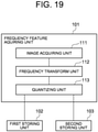
- a quantizing unit 113 having the same function as the quantizing unit 161 included by the frequency feature synthesizing unit 104 may be included by the frequency feature acquiring unit 101 as shown in Fig. 19 .
- the quantizing unit 113 is configured to quantize the real parts and imaginary parts of the respective elements of the frequency feature of the first image and the frequency feature of the second image generated by the frequency transform unit 112 of the frequency feature acquiring unit 101 into binary values, and store the quantized frequency feature of the first image and the quantized frequency feature of the second image into the first storing unit 102 and the second storing unit 103, respectively.
- the synthesizing unit 162 of the frequency feature synthesizing unit 104 is configured to retrieve the quantized frequency feature of the first image and the quantized frequency feature of the second image from the first storing unit 102 and the second storing unit 103, respectively.
- An image matching apparatus 400 according to this example embodiment is different in the frequency feature acquiring unit 101 from the image matching apparatuses according to the first and second example embodiments, and otherwise the same as the image matching apparatuses according to the first and second example embodiments.
- Fig. 20 is a block diagram of the frequency feature acquiring unit 101 in the image matching apparatus 400 according to this example embodiment.
- the frequency feature acquiring unit 101 in this example includes an image acquiring unit 171, a frequency transform unit 172, a polar coordinate transform unit 173, and a frequency transform unit 174.
- the image acquiring unit 171 is configured to acquire the first image and the second image in the same manner as the image acquiring unit 111 shown in Fig. 4 .
- the frequency transform unit 172 is configured to receive the first image and the second image from the image acquiring unit 172, apply the discrete Fourier transform to each of the images, and calculate a two-dimensional amplitude spectrum from the result. This two-dimensional amplitude spectrum is invariant to the translation of the original image.
- the polar coordinate transform unit 173 is configured to receive the two-dimensional amplitude spectrum of the first image and the two-dimensional amplitude spectrum of the second image from the frequency transform unit 172, apply polar coordinate transform or log polar coordinate transform to the amplitude spectrums, and calculate polar coordinate images.
- the polar coordinate image is referred to as a Fourier-Mellin feature image. Changes in magnification and rotation of the original image are transformed into changes in translation in the Fourier-Mellin feature image.
- the frequency transform unit 174 is configured to receive the Fourier-Mellin feature image of the first image and the Fourier-Mellin feature image of the second image from the polar coordinate transform unit 173, apply the discrete Fourier transform to the Fourier-Mellin transform images, and thereby calculate phase images.
- the phase image is referred to as a Fourier-Mellin frequency spectrum image.
- the Fourier-Mellin frequency spectrum image is invariant to the magnification, rotation, and translation of the original image.
- the frequency transform unit 174 stores the Fourier-Mellin frequency spectrum image of the first image into the first storing unit 102, and stores the Fourier-Mellin frequency spectrum image of the second image into the second storing unit 103.
- the image matching apparatus 400 can perform match of the first image and the second image at high speeds. Moreover, it is possible to perform the matching robustly against the magnification, rotation, and translation of the first and second images.
- the polar coordinate transform unit 173 in Fig. 20 may be omitted.
- the frequency transform unit 174 is configured to receive the two-dimensional amplitude spectrum of the first image and the two-dimensional amplitude spectrum of the second image from the frequency transform unit 172, and store the phase images obtained by applying the discrete Fourier transform to the two-dimensional spectrums into the first storing unit 102 and the second storing unit 103, respectively.
- the image matching apparatuses according to the first to third example embodiments described above use the inside of the region of the frequency feature of the first image and the inside of the region of the frequency feature of the second image for matching without discrimination.
- the image matching apparatus according to this example embodiment uses the inside of the region of the frequency feature of the first image and the inside of the region of the frequency feature of the second image for matching with discrimination.
- the image matching apparatus divides the region of a frequency feature into a plurality of partial regions, and sets the effectiveness of a partial region that adversely affects matching to be lower than that of the other partial region or does not use such a partial region, thereby reducing an influence on matching.
- Fig. 21 is a block diagram of the frequency feature acquiring unit 101 in an image matching apparatus 500 according to this example embodiment.
- the frequency feature acquiring unit 101 in this example has a configuration in which a weighting unit 175 is added to the frequency feature acquiring unit 101 shown in Fig. 20 .
- the weighting unit 175 is configured to receive a first frequency feature and a second frequency feature from the frequency transform unit 174, and assign a weight to each partial region thereof.
- one element of a frequency feature may be one partial region, or a set of adjacent elements may be one partial region.
- the weights to be assigned may take, for example, values from 0 to 1, and may have a lower effectiveness degree as is closer to 0.
- a criterion for assigning a weight to a partial region is set in advance. For example, in a case where existence of a frequency band important for matching is found by a statistical method, a criterion to assign a larger weight to a partial region corresponding to the frequency band important for matching than to the other partial regions may be used. Alternatively, in a case where existence of an image component common to a number of images is found by a statistical method, a criterion to assign a smaller weight to a partial region containing the common image component than to the other partial regions may be used.
- the frequency feature synthesizing unit 104 removes a partial region with the assigned weight equal to or less than a reference value and calculates a normalized cross power spectrum of the first frequency feature and the second frequency feature composed of the remaining partial regions.
- the frequency feature synthesizing unit 104 calculates a quantized normalized cross power spectrum obtained by assigning, to the product of an element of the first frequency feature and an element of the complex conjugate of the second frequency feature, a weight corresponding to weights assigned to the original elements (for example, a value obtained by multiplying both the weights).
- a weight corresponding to weights assigned to the original elements for example, a value obtained by multiplying both the weights.
- the square wave determining unit 105 considers the weight assigned to an element of the normalized cross power spectrum.
- the image matching apparatus 500 can match the first image against the second image at high speeds for the same reason as the image matching apparatuses of the first to third example embodiments. Moreover, even if the first image and the second image contain a partial region that adversely effects matching, it is possible to reduce an influence on the matching.
- FIG. 22 is a block diagram of an image matching apparatus 600 according to this example embodiment.
- the image matching apparatus 600 is configured to match the first image against the second image.
- the image matching apparatus 600 includes an acquiring unit 601, a generating unit 602, and a determining unit 603.
- the acquiring unit 601 is configured to acquire a frequency feature of the first image and a frequency feature of the second image.
- the acquiring unit 601 can be configured in the same manner as the frequency feature acquiring unit 101 of Fig. 1 , but is not limited thereto.
- the generating unit 602 is configured to synthesize the frequency feature of the first image and the frequency feature of the second image acquired by the acquiring unit 601, and generate a quantized synthesized frequency feature in which the value of an element is expressed by a binary value or a ternary value.
- the generating unit 602 can be configured in the same manner as the frequency feature synthesizing unit 104 of Fig. 4 , but is not limited thereto.
- the determining unit 603 is configured to calculate a score indicating a degree that the quantized synthesized frequency feature generated by the generating unit 602 is a square wave having a single period, and match the first image against the second image based on the score.
- the determining unit 603 can be configured in the same manner as the square wave determining unit 105 of Fig. 1 , but is not limited thereto.
- the image matching apparatus 600 thus configured operates in the following manner.
- the acquiring unit 601 acquires the frequency feature of the first image and the frequency feature of the second image.
- the generating unit 602 synthesizes the frequency feature of the first image and the frequency feature of the second image acquired by the acquiring unit 601, and generates a quantized synthesized frequency feature in which the value of each element is represented by a binary value or a ternary value.
- the determining unit 603 calculates a score indicating a degree that the quantized synthesized frequency feature generated by the generating unit 602 is a square wave having a single period, and matches the first image against the second image based on the score.
- the present invention can be used in the field of matching two images against each other and in particular, the present invention can be used in the field of performing individual identification and management of each product by acquiring a difference in naturally occurring minute pattern arising in the same production process, such as minute irregularities and patterns on the product surface, and a random pattern on the material surface, as an image with an imaging device such as a camera, and recognizing the minute pattern.
- the present invention can be used not only for products, but also in the field of individual authentication or identification and management of a living body by acquiring a difference in surface fine pattern of living things such as human fingerprints as an image with an imaging device such as a camera and recognizing the fine pattern.
- An image matching apparatus matching a first image against a second image comprising:
- the generating unit includes:
- the quantizing unit is configured to transform the value of the element into a binary value or a ternary value based on a sign of a real part of the element.
- the quantizing unit is configured to transform the value of the element into a binary value or a ternary value based on a sign of an imaginary part of the element.
- the generating unit includes:
- the quantizing unit is configured to transform the values of the real parts and the imaginary parts of the elements into binary values based on signs of the real parts and the imaginary parts of the elements.
- the image matching apparatus according to any of Supplementary Notes 1 to 6, wherein the determining unit is configured to perform orthogonal transformation using a Hadamard matrix on the quantized synthesized frequency feature, and calculate the score based on data obtained by the orthogonal transformation.
- the determining unit is configured to calculate the score based on a maximum value of degrees of similarity between a plurality of post-shift quantized synthesized frequency features and the quantized synthesized frequency feature before circular shift, the plurality of post-shift quantized synthesized frequency features being obtained by performing the circular shift on the quantized synthesized frequency feature by different circular shift amounts, respectively.
- the image matching apparatus according to any of Supplementary Notes 1 to 6, wherein the determining unit is configured to calculate the score based on a maximum value of degrees of similarity between a plurality of reference quantized synthesized frequency features having different periods, respectively, and the quantized synthesized frequency feature.
- the image matching apparatus according to any of Supplementary Notes 1 to 9, wherein the acquiring unit is configured to divide the frequency feature of the first image and the frequency feature of the second image into a plurality of partial regions, and assign a degree of effectiveness relating to calculation of the score to each of the partial regions.
- An image matching method for matching a first image against a second image comprising:
- the transforming includes transforming the value of the element into a binary value or a ternary value based on a sign of a real part of the element.
- the transforming includes transforming the value of the element into a binary value or a ternary value based on a sign of an imaginary part of the element.
- the image matching method wherein the generating the first quantized frequency feature and the second quantized frequency feature includes transforming the values of the real parts and the imaginary parts of the elements into binary values based on signs of the real parts and the imaginary parts of the elements.
- the calculating the score includes performing orthogonal transformation using a Hadamard matrix on the quantized synthesized frequency feature, and calculating the score based on data obtained by the orthogonal transformation.
- the calculating the score includes calculating the score based on a maximum value of degrees of similarity between a plurality of post-shift quantized synthesized frequency features and the quantized synthesized frequency feature before circular shift, the plurality of post-shift quantized synthesized frequency features being obtained by performing the circular shift on the quantized synthesized frequency feature by different circular shift amounts, respectively.
- the calculating the score includes calculating the score based on a maximum value of degrees of similarity between a plurality of reference quantized synthesized frequency features having different periods, respectively, and the quantized synthesized frequency feature.
- the image matching method includes dividing the frequency feature of the first image and the frequency feature of the second image into a plurality of partial regions, and assigning a degree of effectiveness relating to calculation of the score to each of the partial regions.
Landscapes
- Engineering & Computer Science (AREA)
- Theoretical Computer Science (AREA)
- Computer Vision & Pattern Recognition (AREA)
- General Physics & Mathematics (AREA)
- Physics & Mathematics (AREA)
- Multimedia (AREA)
- Computing Systems (AREA)
- General Health & Medical Sciences (AREA)
- Medical Informatics (AREA)
- Software Systems (AREA)
- Evolutionary Computation (AREA)
- Databases & Information Systems (AREA)
- Artificial Intelligence (AREA)
- Health & Medical Sciences (AREA)
- Image Analysis (AREA)
- Collating Specific Patterns (AREA)
Abstract
Description
- The present invention relates to an image matching apparatus, an image matching method, and a program.
- Various image matching methods for matching a compared image against a registered image for the purpose of individual identification and so on have been proposed or put into practical use.
- For example, in
Patent Document 1, first, a compared image and a registered image are transformed into the frequency domain by using the Fourier transform. Next, a cross power spectrum is calculated from the respective complex spectra of the compared image and the registered image obtained by the above transformation. Next, the cross power spectrum is normalized to phase components alone by eliminating power components using a weight filter for each frequency. Next, a correlation efficient on a real coordinate domain is calculated by applying the inverse Fourier transform to the normalized cross power spectrum. Next, pattern matching determination is performed by using coordinates that make the calculated correlation coefficient the maximum value. - Further, in
Patent Document 2, a registered Fourier image is created in advance by applying the Fourier transform to a registered image. Next, a compared Fourier image is created by applying the Fourier transform to a compared image. Next, the compared Fourier image and the registered Fourier image created in advance are synthesized. Next, an amplitude suppression process is performed on the above synthesized Fourier image and then the inverse Fourier transform is applied. Next, the upper n pixels with correlation components having higher intensity are extracted from a predetermined correlation component area appearing in the synthetized Fourier image with the inverse Fourier transform applied. Then, based on the intensity of the correlation components of the extracted n pixels, it is determined whether or not the registered image and the compared image match. - Further, in
Non-Patent Document 1, by obtaining a normalized cross power spectrum that is a synthesized frequency feature obtained by synthesizing the frequency feature of a registered image and the frequency feature of a compared image, and determining a distribution shape in the frequency feature, the compared image is matched against the registered image. Non-PatentDocument 1 focuses on that in the case of a pair of identical images with a position gap, a normalized cross power spectrum of the frequency features of the two images becomes a complex sine wave having a single period with respect to a discrete frequency index. Then, inNon-Patent Document 1, by calculation of the partial differential of the normalized cross power spectrum, calculation of the absolute values of the elements with respect to the obtained differential result, and calculation of the variance of the obtained absolute values, a score indicating a degree that the normalized cross power spectrum of the frequency features of the two images is a complex sine wave having a single period is calculated, and the two images are matched against each other based on the score. -
- Patent Document 1:
Japanese Unexamined Patent Application Publication No. JP-A 2008-015848 - Patent Document 2:
Japanese Patent No.3254622 - Non-Patent Document 1: Toru Takahashi, Kengo Makino, Yuta Kudo, Rui Ishiyama, "A Study of Fast Image Matching Method Under Translation, Scale, and Rotation", IEICE Technical Report, BioX2017-42, PRMU2017-178 , March 2018
- As described in
Patent Document 1 andPatent Document 2, in the case of matching two images against each other, it is general to use the result of synthesizing the frequency features of the two images and applying the inverse Fourier transform to the synthesized frequency feature. However, the complexity of the inverse Fourier transform is large. Therefore, it is difficult to match two images against each other at high speeds. - On the other hand, according to the image matching technique described in
Non-Patent Document 1, the inverse Fourier transform is not required, and the matching score can be calculated by lighter operations. However, although it is lighter than the inverse Fourier transform, the complexity required to calculate the matching score is still large. The reason is as follows. In order to calculate a score indicating a degree that the normalized cross power spectrum of the frequency features of two images is a complex sine wave having a single period, there is a need to obtain the normalized cross power spectrum as a complex sine wave while minimizing an error. For this, many bits need to be allocated to represent the elements of the normalized cross power spectrum. Then, as the number of bits representing the elements increases, the complexity of the abovementioned partial differential calculation, calculation of absolute values of the elements, and calculation of variance of the obtained absolute values for calculating a score indicating a degree that the normalized cross power spectrum is a complex sine wave having a single period increases. - An object of the present invention is to provide an image matching apparatus that solves the abovementioned problem; it is difficult to match two images against each other at high speeds.
- An image matching apparatus according to an aspect of the present invention is an image matching apparatus matching a first image against a second image. The image matching apparatus includes: an acquiring unit configured to acquire a frequency feature of the first image and a frequency feature of the second image; a generating unit configured to synthesize the frequency feature of the first image and the frequency feature of the second image, and generate a quantized synthesized frequency feature in which a value of an element is represented by a binary value or a ternary value; and a determining unit configured to calculate a score indicating a degree to which the quantized synthesized frequency feature is a square wave having a single period, and match the first image against the second image based on the score.
- Further, an image matching method according to another aspect of the present invention is an image matching method for matching a first image against a second image. The image matching method includes: acquiring a frequency feature of the first image and a frequency feature of the second image; synthesizing the frequency feature of the first image and the frequency feature of the second image, and generating a quantized synthesized frequency feature in which a value of an element is represented by a binary value or a ternary value; and calculating a score indicating a degree to which the quantized synthesized frequency feature is a square wave having a single period, and matching the first image against the second image based on the score.
- Further, a non-transitory computer-readable recording medium according to another aspect of the present invention has a program recorded thereon. The program includes instructions for causing a computer matching a first image against a second image to execute: a process of acquiring a frequency feature of the first image and a frequency feature of the second image; a process of synthesizing the frequency feature of the first image and the frequency feature of the second image, and generating a quantized synthesized frequency feature in which a value of an element is represented by a binary value or a ternary value; and a process of calculating a score indicating a degree to which the quantized synthesized frequency feature is a square wave having a single period, and matching the first image against the second image based on the score.
- With the configurations described above, the present invention enables high-speed matching of a first image and a second image.
-
-
Fig. 1 is a block diagram of an image matching apparatus according to a first example embodiment of the present invention; -
Fig. 2 is a block diagram showing an example of a hardware configuration of the image matching apparatus according to the first example embodiment of the present invention; -
Fig. 3 is a flowchart showing the outline of an operation of the image matching apparatus according to the first example embodiment of the present invention; -
Fig. 4 is a block diagram showing an example of a frequency feature acquiring unit in the image matching apparatus according to the first example embodiment of the present invention; -
Fig. 5 is a view showing an example of formulas representing the frequency feature of a first image and the frequency feature of a second image; -
Fig. 6 a view showing an example of an image of amplitude components AF(k1, k2) and AG(k1, k2), and phase components θF(k1, k2) and θG(k1, k2); -
Fig. 7 is a block diagram showing a configuration example of a frequency feature synthesizing unit in the image matching apparatus according to the first example embodiment of the present invention; -
Fig. 8 is a view showing an example of a formula for calculating a normalized cross power spectrum; -
Fig. 9 is a view showing an example of formulas showing a frequency feature F(k1, k2), a frequency feature G(k1, k2), and a normalized cross power spectrum R(k1, k2) of a pair of identical images with position gap; -
Fig. 10 is a view showing an example of an image of the normalized cross power spectrum R(k1, k2) of the pair of identical images; -
Fig. 11 is a view showing an example of an image in which the normalized cross power spectrum of the pair of identical images is quantized into binary data; -
Fig. 12 is a block diagram showing an example of a square wave determining unit in the image matching apparatus according to the first example embodiment of the present invention; -
Fig. 13 is an explanatory view of a Hadamard matrix; -
Fig. 14 is a view showing an equation representing orthogonal transformation using the Hadamard matrix; -
Fig. 15 is a block diagram showing another example of the square wave determining unit in the image matching apparatus according to the first example embodiment of the present invention; -
Fig. 16 is a block diagram showing still another example of the square wave determining unit in the image matching apparatus according to the first example embodiment of the present invention; -
Fig. 17 is a block diagram showing a configuration example of a frequency feature synthesizing unit in an image matching apparatus according to a second example embodiment of the present invention; -
Fig. 18 is a conceptual view showing an example of an operation of quantizing each of a real part and an imaginary part of an element of a frequency feature; -
Fig. 19 is a block diagram showing a configuration example of a frequency feature synthesizing unit in a modified example of the image matching apparatus according to the second example embodiment of the present invention; -
Fig. 20 is a block diagram showing a configuration example of a frequency feature synthesizing unit in an image matching apparatus according to a third example embodiment of the present invention; -
Fig. 21 is a block diagram showing a configuration example of a frequency feature synthesizing unit in an image matching apparatus according to a fourth example embodiment of the present invention; and -
Fig. 22 is a block diagram of an image matching apparatus according to a fifth example embodiment of the present invention. - Next, example embodiments of the present invention will be described in detail with reference to the drawings.
-
Fig. 1 is a block diagram of an image matching apparatus according to a first example embodiment of the present invention. Animage matching apparatus 100 according to this example embodiment is configured to match a first image against a second image. Referring toFig. 1 , theimage matching apparatus 100 includes a frequencyfeature acquiring unit 101, afirst storing unit 102, asecond storing unit 103, a frequencyfeature synthesizing unit 104, a squarewave determining unit 105, and aninformation presenting unit 106. - The frequency
feature acquiring unit 101 is configured to acquire the frequency features of a first image and a second image. A frequency feature refers to two-dimensional data (two-dimensional array) as a result of applying the Fourier transform (discrete Fourier transform) to an image and thereby transforming into the frequency domain. Frequency transform other than the Fourier transform, for example, Wavelet transform may be performed. - Herein, a first image is, for example, a compared image obtained by imaging an object to be compared. A second image is one of a plurality of registered images obtained by imaging a plurality of objects to be registered. One or a plurality of second images are present. An object is, for example, an industrial product, a commercial product, or the like. On the surface of an object, there is a fine pattern that naturally occurs in the same production process such as fine irregularities or patterns or a random pattern on the material surface. By acquiring a difference in such a pattern on the surface of an object as an image by an imaging device such as a camera and recognizing the fine pattern, it is possible to perform individual identification and management of each product. This example embodiment relates to an image matching technique for such individual identification.
- The
first storing unit 102 is configured to store the frequency feature of the first image. Thesecond storing unit 103 is configured to store the frequency feature of the second image. - The frequency
feature synthesizing unit 104 is configured to synthesize the frequency feature of the first image stored in thefirst storing unit 102 and the frequency feature of the second image stored in thesecond storing unit 103, and calculate a normalized cross power spectrum in which the values of elements are represented by binary or ternary values (hereinafter, referred to as a quantized cross power spectrum). - The square
wave determining unit 105 is configured to calculate a score indicating a degree that the quantized cross power spectrum calculated by the frequencyfeature synthesizing unit 104 is a square wave signal having a single period. Moreover, the squarewave determining unit 105 is configured to match the first image against the second image based on the calculated score. That is to say, the squarewave determining unit 105 uses a score indicating a degree that a quantized cross power spectrum quantized into binary or ternary values is a square wave signal having a single period, as a score representing the degree of similarity between the first image and the second image. - The
information presenting unit 106 is configured to present the result of matching of the first image and the second image based on the result of determination by the squarewave determining unit 105. The presentation of the matching result may be, for example, displaying the matching result on a display device, or printing the matching result on a sheet of paper by a printing device, or transmitting a message describing the matching result to an external terminal by a communication device. - For example, as shown in
Fig. 2 , theimage matching apparatus 100 can be realized by aninformation processing device 200 that includes animaging unit 201 such as a camera, anoperation input unit 202 such as a keyboard and a mouse, ascreen display unit 203 such as a liquid crystal display, acommunication interface unit 204, astoring unit 205 such as a memory and a hard disk and anarithmetic processing unit 206 such as one or more microprocessors, and aprogram 207. Theinformation processing device 200 may be, for example, a personal computer or a smartphone. - The
program 207 is loaded into a memory from an external computer-readable storage medium when theinformation processing device 200 is started, and controls an operation of thearithmetic processing unit 206 to realize on thearithmetic processing unit 206 functional units such as the frequencyfeature acquiring unit 101, thefirst storing unit 102, thesecond storing unit 103, the frequencyfeature synthesizing unit 104, the squarewave determining unit 105, and theinformation presenting unit 106. - Next, the outline of an operation of the
image matching apparatus 100 according to this example embodiment will be described. -
Fig. 3 is a flowchart showing the outline of the operation of theimage matching apparatus 100. First, the frequencyfeature acquiring unit 101 acquires the frequency feature of the first image and the frequency feature of the second image (step S1). In a case where a plurality of second images are present, the frequencyfeature acquiring unit 101 acquires a frequency feature from each of the second images. The frequencyfeature acquiring unit 101 stores the acquired frequency feature of the first image into thefirst storing unit 102, and stores the acquired frequency feature of the second image into thesecond storing unit 103. - Next, the frequency
feature synthesizing unit 104 calculates a normalized cross power spectrum of the frequency feature of the first image stored in thefirst storing unit 102 and the frequency feature of the second image stored in the second storing unit 103 (step S2). In a case where there are a plurality of frequency features of second images, the frequencyfeature synthesizing unit 104 calculates a plurality of normalized cross power spectra of the frequency feature of the first image and the respective frequency features of the second images. Moreover, the frequencyfeature synthesizing unit 104 quantizes the calculated normalized cross power spectrum, and transforms the value of each of the elements to binary or ternary data (step S3). In a case where there are a plurality of normalized cross power spectra, the frequencyfeature synthesizing unit 104 quantizes the respective normalized cross power spectra. - Next, the square
wave determining unit 105 calculates a score indicating a degree that the quantized cross power spectrum obtained from the frequencyfeature synthesizing unit 104 is a square wave having a single period (step S4). When a plurality of quantized cross power spectra are present, the squarewave determining unit 105 calculates, for each of the quantized cross power spectra, a score indicating a degree that it is a square wave having a single period. - Next, the square
wave determining unit 105 matches the first image against the second image based on the calculated score (step S5). - For example, in a case where there is one second image, the square
wave determining unit 105 derives a matching result indicating that the first image and the second image match (identical) when the score satisfies a predetermined reference value. On the other hand, when the score does not satisfy the predetermined reference value, the squarewave determining unit 105 derives a matching result indicating that the first image and the second image do not match (not identical). - Further, for example, in a case where a plurality of second images are present, when a best score among a plurality of scores calculated for a plurality of cross power spectra corresponding to the plurality of second images satisfies a predetermined reference value, the square
wave determining unit 105 derives a matching result indicating that the first image and the second image of the best score match (identical). On the other hand, when the best score does not satisfy the predetermined reference value, the squarewave determining unit 105 derives a matching result indicating that the first image and the second image do not match (not identical). - Next, the
information presenting unit 106 presents the result of matching of the first image and the second image obtained from the squarewave determining unit 105. - Next, the respective units of the
image matching apparatus 100 according to this example embodiment will be described in detail. - First, the frequency
feature acquiring unit 101 will be described in detail. -
Fig. 4 is a block diagram showing an example of the frequencyfeature acquiring unit 101. The frequencyfeature acquiring unit 101 in this example includes animage acquiring unit 111 and afrequency transform unit 112. - The
image acquiring unit 111 is configured to acquire the first image and the second image. Theimage acquiring unit 111 may be, for example, image capture equipment typified by a camera, a scanner, and the like. Alternatively, theimage acquiring unit 111 may be an optical sensor that collects visible light and light having a wavelength longer than visible light such as near-infrared light, short-wavelength infrared light and thermal infrared light with a lens and acquires the shape of a target object, or the like, as image data. Alternatively, theimage acquiring unit 111 may be a sensor that acquires the intensity of infrared light, ultraviolet light or X-ray and outputs as a two-dimensional data array. Alternatively, theimage acquiring unit 111 may be configured to acquire the first image and the second image from an external storage medium such as a CD-ROM or a memory. Alternatively, theimage acquiring unit 111 may be configured to receive the first image and the second image via a network. Moreover, theimage acquiring unit 111 may acquire the first image and the second image by different methods, respectively. - The
frequency transform unit 112 is configured to receive the first image and the second image from theimage acquiring unit 111, and output an image (a frequency spectrum image) as a result of applying discrete Fourier transform to each of the images. Thefrequency transform unit 112 stores the frequency spectrum image of the first image as a first frequency feature into thefirst storing unit 102, and stores the frequency spectrum of the second image as a second frequency feature into thesecond storing unit 103. - Next, an example of the frequency features of the first and second images acquired by the frequency
feature acquiring unit 101 will be described. - Let the first image and the second image be two images f(n1, n2) and g(n1, n2) of N1×N2 pixels. Moreover, let a discrete space index (integer) of a two-dimensional image signal be n1 = -M1, ..., M1 and n2 = -M2, ..., M2. Herein, M1 and M2 are positive integers, and N1 = 2M1+1 and N2 = 2M2+1. Then, a first frequency feature F(k1, k2) obtained by applying two-dimensional discrete Fourier transform to the image f(n1, n2) and a second frequency feature G(k1, k2) obtained by applying two-dimensional discrete Fourier transform to the image g(n1 ,n2) are given by
Equations Fig. 5 . InEquations Fig. 5 . Moreover, AF(k1, k2) and AG(k1, k2) represent amplitude spectra (amplitude components), and θF(k1, k2) and θG(k1, k2) represent phase spectra (phase components), respectively. Moreover, ∑n1,n2 represents addition over the entire index range as shown inEquation 5 ofFig. 5 . -
Fig. 6 shows an example of the image of the amplitude components AF(k1, k2) and AG(k1, k2) and the phase components θF(k1, k2) and θG(k1, k2). - Next, the frequency
feature synthesizing unit 104 will be described in detail. -
Fig. 7 is a block diagram showing an example of the frequencyfeature synthesizing unit 104. The frequencyfeature synthesizing unit 104 in this example includes asynthesizing unit 121 and aquantizing unit 122. - The synthesizing
unit 121 calculates a normalized cross power spectrum R(k1, k2) of the first frequency feature F(k1, k2) and the second frequency feature G(k1, k2) by Equation 6 shown inFig. 8 . In Equation 6, overline G(k1, k2) is a complex conjugate of the second frequency feature G(k1, k2). Moreover, θF(k1, k2)-θG(k1, k2) is a phase difference spectrum of the first frequency feature and the second frequency feature. As shown in Equation 6, the frequencyfeature synthesizing unit 104 obtains a cross power spectrum that is the product for each element of the first frequency feature F(k1, k2) and the complex conjugate of the second frequency feature G(k1, k2) and normalizes with the absolute value thereof, thereby calculating the normalized cross power spectrum. - In a case where the image f(n1, n2) and the image g(n1, n2) are a pair of identical images with position gap, the frequency feature F(k1, k2) and the frequency feature G(k1, k2) of the images, and the normalized cross power spectrum R(k1, k2) of the two frequency features are given by
Equations Fig 9 . Herein, δ1 and δ2 denote the amount of position gap between the image f(n1, n2) and the image g(n1, n2). That is to say, the image g(n1, n2) is an image obtained by translating the image f(n1, n2) by (δ1, δ2). As shown inEquation 9, in a case where the two frequency features F(k1, k2) and G(k1, k2) to be matched are a pair of identical images, the normalized cross power spectrum R(k1, k2) thereof is expressed as a complex sine wave having a single period for each of the dimensions (each of k1 and k2). On the other hand, in a case where the two frequency features F(k1, k2) and G(k1, k2) to be matched are not a pair of identical images, the normalized cross power spectrum R(k1, k2) is not a complex sine wave having a single period for each of the dimensions. -
Fig. 10 shows an example of the image of the normalized cross power spectrum R (k1, k2) of a pair of identical images. Thus, a normalized cross power spectrum of a pair of identical images has an image like a wave having a single period when a bright portion is regarded as a peak and a dark portion is regarded as a trough. - The
quantizing unit 122 quantizes each element of the normalized cross power spectrum obtained by the synthesizingunit 121 into binary or ternary data. A method for such quantization can be any method. For example, a quantization method as described below may be used. - The
quantizing unit 122 substitutes a value (composed of a real part and an imaginary part) of each element of the normalized cross power spectrum obtained by the synthesizingunit 121 with a value obtained by quantizing a predetermined one of the real part and the imaginary part of each element to a binary or ternary value. For example, let the value of a certain element U be A+Bj. Herein, A and B are real numbers, and j is an imaginary unit. In the case of quantizing the element U into a binary value, thequantizing unit 122 transforms A+Bj to "+1" if A≧0, and transforms A+Bj to "-1" if A<0, for example. In this example, thequantizing unit 122 quantizes into a binary value based on the sign of the real number A of the real part, but may quantize into a binary value based on the sign of the real number B of the imaginary part. In the case of quantizing the element U into a ternary value, thequantizing unit 122 transforms A+Bj to "+1" if A≧0, transforms to "0" if A=0, and transforms A+Bj to "-1" if A<0, for example. In this example, thequantizing unit 122 quantizes into a binary value based on the sign of the real number A of the real part, but may quantize into a binary value based on the sign of the real number B of the imaginary part. According to the quantizing method as described above, thequantizing unit 122 represents each element of the normalized cross power spectrum obtained by the synthesizingunit 121 as 1-bit or 2-bit data. - The reason that the
quantizing unit 122 quantizes each element of the normalized cross power spectrum into binary or ternary data is as follows. - In general, a real part and an imaginary part of each element of the normalized cross power spectrum R (k1, k2) are calculated as real number values (floating point numbers), and many bits are required to represent each element (for example, 64-bit data for double precision floating point numbers, and 32-bit data for single precision floating point numbers). In the application of alignment between images to accurately obtain the amount of position gap between images, it is important to obtain a normalized cross power spectrum as a complex sine wave with as little error as possible and obtain the period of the complex sine wave with accuracy. On the other hand, in the application of determining whether two images are identical or not as in the example embodiment of the present invention, it is not necessary to accurately calculate a normalized cross power spectrum as a complex sine wave. That is to say, it is important whether a normalized cross power spectrum has a distribution as periodic data with repetition. Even if each element of a normalized cross power spectrum is quantized into binary or ternary data and the amount of information of each element is reduced, it is possible to determine whether obtained data distribution is distribution as a periodic repetition pattern. Therefore, even if the information is reduced, the accuracy of matching and identification does not deteriorate extremely. Based on this, in this example embodiment, the
quantizing unit 122 quantizes each element of a normalized cross power spectrum obtained by the synthesizingunit 121 into binary or ternary data. -
Fig. 11 shows an example of an image in which the normalized cross power spectrum R(k1, k2) of a pair of identical images is quantized into binary data. Thus, in the data obtained by quantizing the normalized cross power spectrum of a pair of identical images into binary data, the pattern of a wave having a single period in which a light portion is regarded as a peak and a dark portion is regarded as a trough can be kept. Therefore, even if a normalized cross power spectrum that is real number data represented by 32-bit or 64-bit conventionally is quantized into binary (1-bit) or ternary (2-bit) data to reduce the amount of data, it is possible to determine the presence or absence of a correlation between input images without lowering accuracy. That is to say, it is possible to realize distinguishing a pair of identical images having a correlation from a pair of different images having no correlation with less data amount without impairing accuracy. - Next, the square
wave determining unit 105 will be described in detail. As mentioned before, the squarewave determining unit 105 quantifies a degree that a normalized cross power spectrum with elements quantized into binary or ternary values calculated by the frequencyfeature synthesizing unit 104 is a square wave having a single period, and outputs as a score. -
Fig. 12 is a block diagram showing an example of the squarewave determining unit 105. The squarewave determining unit 105 in this example includes, for example, anorthogonal transformation unit 131 that performs orthogonal transformation using a Hadamard matrix. A Hadamard matrix is a square matrix whose elements are "+1" and "-1" and whose rows are mutually orthogonal. Considering a case where a Hadamard matrix Hm is an m×m matrix and m=2P (P is a positive integer), the Hadamard matrix Hm is defined asEquations Fig. 13 . - The
orthogonal transformation unit 131 is configured to perform orthogonal transformation using a Hadamard matrix on a normalized cross power spectrum quantized into binary or ternary values and output the maximum value of the output as a score. In a case where the quantized normalized cross power spectrum is a square wave having a single period, a sharp peak value of the period appears in the output by theorthogonal transformation unit 131. On the other hand, in a case where the quantized normalized cross power spectrum is not a square wave having a single period, a sharp peak value does not appear in the output by theorthogonal transformation unit 131. Therefore, the maximum value of the output by theorthogonal transformation unit 131 can be a score indicating a degree that the quantized normalized cross power spectrum is a square wave having a single period. Theorthogonal transformation unit 131 matches images against each other based on the calculated score. - The orthogonal transformation using the Hadamard matrix performed by the
orthogonal transformation unit 131 is described byEquation 12 ofFig. 14 . InEquation 12, HN denotes a Hadamard matrix, X denotes an N×N input signal (quantized cross power spectrum), and Y denotes an N×N output signal (score). In the case of a normalized cross power spectrum quantized into binary values ("+1" and "-1"), the operation ofEquation 12 can be executed by logical operation such as exclusive OR (XOR), bit counting, and a combination of addition and subtraction, so that high-speed processing is possible. Moreover, in the case of a normalized cross power spectrum quantized into ternary values ("+1", "0", and "-1"), the operation ofEquation 12 can be executed by logical operation such as exclusive OR (XOR), bit counting, and a combination of addition and subtraction on the elements "+1" and "-1" without executing the operation on the elements having a value of "0", so that high-speed processing is possible. -
Fig. 15 is a block diagram showing another example of the squarewave determining unit 105. The squarewave determining unit 105 of this example includes a circularshift processing unit 141 and a similaritydegree calculating unit 142. - The circular
shift processing unit 141 is configured to input a normalized cross power spectrum with elements quantized into binary or ternary values (hereinafter referred to as data before circular shift) and output a quantized cross power spectrum with the elements circularly shifted by a rotate no carry operation or the like (hereinafter referred to as data after circular shift). Moreover, the circularshift processing unit 141 is configured to variously change a circular shift amount and thereby output a plurality of data after circular shift having different circular shift amounts. - The similarity
degree calculating unit 142 is configured to input data before circular shift and a plurality of data after circular shift with different circular shift amounts, and calculate a plurality of similarity degrees between the data before circular shift and the plurality of data after circular shift. Moreover, the similaritydegree calculating unit 142 is configured to output the maximum similarity degree among the calculated similarity degrees as a score. The similaritydegree calculating unit 142 performs image matching based on the calculated score. - In a case where the data before circular shift is a square wave having a single period, when the circular
shift processing unit 141 circularly shifts the data before circular shift, a square wave having the same single period as the data before circular shift periodically appears as the data after circular shift. On the other hand, in a case where the data before circular shift is not a square wave having a single period, even when the circularshift processing unit 141 circularly shifts the data before circular shift with various shift amounts, data after circular shift having the same pattern as the data before circular shift does not appear. Therefore, by repeatedly performing the calculation of the similarity degree between the data before circular shift and the data after circular shift while changing the circular shift amount, and using the maximum value of the similarity degree as a score, it is possible to calculate a score representing a degree that the quantized cross power spectrum is a square wave having a single period. - The abovementioned circular
shift processing unit 141 can be implemented by a bit shift operation. Moreover, the abovementioned similaritydegree calculating unit 142 can be implemented by exclusive OR (XOR) and bit count operation for calculating the Hamming distance between the data before circular shift and the data after circular shift. Therefore, a faster calculation than the autocorrelation operation on real number data is possible. -
Fig. 16 is a block diagram showing still another example of the squarewave determining unit 105. The squarewave determining unit 105 of this example includes a square wavepattern storing unit 151 and a similaritydegree calculating unit 152. - The square wave
pattern storing unit 151 is configured to store a plurality of reference square wave patterns. A certain one of the reference square wave patterns is a quantized cross power spectrum obtained by quantizing each element of a normalized cross power spectrum of a pair of identical images with a position gap amount of certain value into a binary or ternary value. The plurality of reference square wave patterns stored in the square wavepattern storing unit 151 differ from each other in position gap amount. - The similarity
degree calculating unit 152 is configured to input a normalized cross power spectrum with elements quantized into binary or ternary values (hereinafter, referred to as a compared square wave pattern) from the frequencyfeature synthesizing unit 104. Moreover, the similaritydegree calculating unit 152 is configured to input a plurality of reference square wave patterns from the square wavepattern storing unit 151. Moreover, the similaritydegree calculating unit 152 is configured to calculate a plurality of similarity degrees between the input compared square waved pattern and the plurality of reference square wave patterns, and output the maximum similarity degree among the plurality of similarity degrees as a score. The similarity degree between the compared square wave pattern and the reference square wave pattern can be obtained by Hamming distance calculation, for example. The similaritydegree calculating unit 152 performs image matching based on the calculated score. - In the case of a pair of identical individuals, that is, in a case where the input two images have a correlation, the normalized cross power spectrum becomes a square wave pattern having a single period, and its period corresponds to the amount of position gap between the two images. Therefore, by finding the range of the repetition error of the amount of position gap at the time of shooting, it is possible to infer the pattern of the square wave arising when there is a correlation. Such a pattern is stored in advance as the reference square wave pattern into the square wave
pattern storing unit 151, and the similaritydegree calculating unit 152 calculates the Hamming distance from the compared square wave pattern, calculates a score representing that the compared square wave pattern is a square wave having a single period based on the distance, and performs the determination. - As described above, according to this example embodiment, it is possible to match the first image against the second image at high speeds. The reason is that a normalized cross power spectrum of the frequency feature of the first image and the frequency feature of the second image is quantized, a score representing a degree that the quantized cross power spectrum is a square wave having a single period is calculated, and the first image and the second image are matched against each other based on the score. That is to say, according to this example embodiment, the
quantizing unit 122 quantizes each element of the normalized cross power spectrum obtained by the synthesizingunit 121 into binary or ternary data, so that it is possible to largely reduce the amount of data processed by the squarewave determining unit 105 as compared with the method described inNon-Patent Document 1, that is, the method of determining whether a normalized cross power spectrum is a complex sine wave having a single period without quantizing the normalized cross power spectrum. It is needless to say that it is possible to reduce the amount of operation necessary for the determination by replacing the similarity degree calculation using the inverse Fourier transform requiring a large amount of calculation as described inPatent Document 1 andPatent Document 2 with the similarity degree calculation process including logical operation such as exclusive OR (XOR) and addition requiring a small amount of calculation. - In this example embodiment, the frequency
feature synthesizing unit 104 calculates a quantized cross power spectrum by quantizing each element of a normalized cross power spectrum of the frequency feature of the first image and the frequency feature of the second image into binary or ternary data. However, even if, after calculation of the cross power spectrum of the frequency feature of the first image and the frequency feature of the second image, the sines (+, -) of the respective elements of the cross power spectrum are converted to "+1, -1" or "+1, 0, -1" without normalizing with amplitude components, the same quantized cross power spectrum as described above can be calculated. Therefore, the frequencyfeature synthesizing unit 104 may be configured to calculate the cross power spectrum of the frequency feature of the first image and the frequency feature of the second image and thereafter quantize into binary or ternary values based on the sign (+, -) of at least one of the real part and the imaginary part of each of the elements. - The first example embodiment has a configuration to perform image matching by using data obtained by quantizing a normalized cross power spectrum obtained by synthesizing the frequency feature of the first image and the frequency feature of the second image into binary or ternary values. On the other hand, this example embodiment has a configuration to quantize the real parts and the imaginary parts of the elements of each of the frequency feature of the first image and the frequency feature of the second image into binary values, and thereafter synthesize the quantized frequency features, and thereby generate a quantized cross power spectrum with the elements represented by ternary values. Moreover, likewise the first example embodiment, this example embodiment has a configuration to calculate a score indicating a degree that the quantized cross power spectrum with the elements represented by ternary values is a square wave having a single period, and match the first image against the second image based on the score. According to this example embodiment, it is possible to largely reduce the data size of the feature values by quantization, and it is possible to process the matching at high speeds.
- This example embodiment is different from the first example embodiment in the configuration and operation of the frequency
feature synthesizing unit 104, and otherwise the same as the first example embodiment. Below, the configuration and operation of the frequencyfeature synthesizing unit 104 in this example embodiment will be described. -
Fig. 17 is a block diagram showing an example of the frequencyfeature synthesizing unit 104 of an image matching apparatus 300 according to this example embodiment. The frequencyfeature synthesizing unit 104 in this example includes aquantizing unit 161 and asynthesizing unit 162. - The
quantizing unit 161 is configured to quantize data of the real parts and the imaginary parts of the elements of the frequency feature of the first image stored in thefirst storing unit 102 into binary data. Moreover, thequantizing unit 161 is configured to quantize data of the real parts and the imaginary parts of the elements of the frequency feature of the second image stored in thesecond storing unit 103 into binary data. Thequantizing unit 161 quantizes, for example, into binary data of "+1" and "-1" based on phase information of the respective elements of the frequency features. -
Fig. 18 is a conceptual view showing an example of an operation of quantizing each of the real part and the imaginary part of an element of a frequency feature. A complex number α of each element of a frequency feature can be represented by α=A+jB, where an imaginary unit is j and real numbers are A and B. Thequantizing unit 161 quantizes by transforming the real numbers A and B into "+1" or "-1" based on the signs of the real numbers A and B and whether or not the real numbers A and B are 0. For example, thee quantizingunit 161 transforms a complex number α where A<0 and B≥0 into [-1, +j]. Moreover, thequantizing unit 161 transforms a complex number α where A≥0 and B<0 into [+1, -j]. - The synthesizing
unit 162 obtains a cross power spectrum that is the product for each element of the frequency feature of the first image and the complex conjugate of the frequency feature of the second image quantized by thequantizing unit 161. Herein, the frequency feature of the first image and the frequency feature of the second image are data in which the real numbers of the real part and the imaginary part have either of two values of "+1" and "-1". Therefore, the synthesizingunit 162 can process at high speeds by a logical operation or the like. Moreover, in the product for each element of the frequency feature of the first image and the complex conjugate of the frequency feature of the second image, the real numbers of the real part and the imaginary part become any of three values of "+2", "0", and "-2". The synthesizingunit 162 outputs at least one of the real part and the imaginary part of the quantized cross power spectrum, as a synthesized frequency feature. For example, the synthesizingunit 162 outputs data obtained by substituting the value of each of the elements of the quantized cross power spectrum with the value of the real part of the element, as a quantized cross power spectrum. Alternatively, the synthesizingunit 162 outputs data obtained by substituting the value of each of the elements of the quantized cross power spectrum with the value of the imaginary part of the element, as a quantized cross power spectrum. The synthesizingunit 162 may be configured to output data obtained by transforming the values "+2" and "-2" of the respective elements of the quantized cross power spectrum into "+1" and "-1", as a quantized cross power spectrum. - The square
wave determining unit 105 in the latter stage quantifies a degree of being a square wave having a single period based on the synthesized frequency feature data quantized into three values and output by the synthesizingunit 162, and outputs as a score. Since the specific processing is the same as described above, a description thereof will be omitted herein. - Thus, according to this example embodiment, it is possible to match the first image against the second image at high speeds. The reason is that a cross power spectrum is calculated by synthesizing after quantizing the real parts and imaginary parts of elements of the frequency feature of a first image and the frequency feature of a second image into binary values, and then a score representing a degree that the quantized cross power spectrum is a square wave having a single period is calculated, and the first image and the second image are matched against each other based on the score. In particular, this example embodiment has an advantage that the feature value data size can be significantly reduced by quantization as compared with the first example embodiment.
- In this example embodiment, the
quantizing unit 161 included by the frequencyfeature synthesizing unit 104 performs quantization of the frequency feature of the first image and the frequency feature of the second image acquired by the frequencyfeature acquiring unit 101. However, aquantizing unit 113 having the same function as thequantizing unit 161 included by the frequencyfeature synthesizing unit 104 may be included by the frequencyfeature acquiring unit 101 as shown inFig. 19 . Thequantizing unit 113 is configured to quantize the real parts and imaginary parts of the respective elements of the frequency feature of the first image and the frequency feature of the second image generated by thefrequency transform unit 112 of the frequencyfeature acquiring unit 101 into binary values, and store the quantized frequency feature of the first image and the quantized frequency feature of the second image into thefirst storing unit 102 and thesecond storing unit 103, respectively. In this modified example, the synthesizingunit 162 of the frequencyfeature synthesizing unit 104 is configured to retrieve the quantized frequency feature of the first image and the quantized frequency feature of the second image from thefirst storing unit 102 and thesecond storing unit 103, respectively. - Next, an image matching apparatus according to a third example embodiment of the present invention will be described. An image matching apparatus 400 according to this example embodiment is different in the frequency
feature acquiring unit 101 from the image matching apparatuses according to the first and second example embodiments, and otherwise the same as the image matching apparatuses according to the first and second example embodiments. -
Fig. 20 is a block diagram of the frequencyfeature acquiring unit 101 in the image matching apparatus 400 according to this example embodiment. The frequencyfeature acquiring unit 101 in this example includes animage acquiring unit 171, afrequency transform unit 172, a polar coordinatetransform unit 173, and afrequency transform unit 174. - The
image acquiring unit 171 is configured to acquire the first image and the second image in the same manner as theimage acquiring unit 111 shown inFig. 4 . - The
frequency transform unit 172 is configured to receive the first image and the second image from theimage acquiring unit 172, apply the discrete Fourier transform to each of the images, and calculate a two-dimensional amplitude spectrum from the result. This two-dimensional amplitude spectrum is invariant to the translation of the original image. - The polar coordinate
transform unit 173 is configured to receive the two-dimensional amplitude spectrum of the first image and the two-dimensional amplitude spectrum of the second image from thefrequency transform unit 172, apply polar coordinate transform or log polar coordinate transform to the amplitude spectrums, and calculate polar coordinate images. The polar coordinate image is referred to as a Fourier-Mellin feature image. Changes in magnification and rotation of the original image are transformed into changes in translation in the Fourier-Mellin feature image. - The
frequency transform unit 174 is configured to receive the Fourier-Mellin feature image of the first image and the Fourier-Mellin feature image of the second image from the polar coordinatetransform unit 173, apply the discrete Fourier transform to the Fourier-Mellin transform images, and thereby calculate phase images. The phase image is referred to as a Fourier-Mellin frequency spectrum image. The Fourier-Mellin frequency spectrum image is invariant to the magnification, rotation, and translation of the original image. Thefrequency transform unit 174 stores the Fourier-Mellin frequency spectrum image of the first image into thefirst storing unit 102, and stores the Fourier-Mellin frequency spectrum image of the second image into thesecond storing unit 103. - For the same reason as the image matching apparatuses according to the first and second example embodiment, the image matching apparatus 400 according to this example embodiment can perform match of the first image and the second image at high speeds. Moreover, it is possible to perform the matching robustly against the magnification, rotation, and translation of the first and second images.
- In an environment where there is no position gap between the first image and the second image in terms of magnification and rotation, the polar coordinate
transform unit 173 inFig. 20 may be omitted. In an image matching apparatus in which the polar coordinatetransform unit 173 is omitted, thefrequency transform unit 174 is configured to receive the two-dimensional amplitude spectrum of the first image and the two-dimensional amplitude spectrum of the second image from thefrequency transform unit 172, and store the phase images obtained by applying the discrete Fourier transform to the two-dimensional spectrums into thefirst storing unit 102 and thesecond storing unit 103, respectively. - Next, an image matching apparatus according to a fourth example embodiment of the present invention will be described. The image matching apparatuses according to the first to third example embodiments described above use the inside of the region of the frequency feature of the first image and the inside of the region of the frequency feature of the second image for matching without discrimination. On the other hand, the image matching apparatus according to this example embodiment uses the inside of the region of the frequency feature of the first image and the inside of the region of the frequency feature of the second image for matching with discrimination. To be specific, the image matching apparatus divides the region of a frequency feature into a plurality of partial regions, and sets the effectiveness of a partial region that adversely affects matching to be lower than that of the other partial region or does not use such a partial region, thereby reducing an influence on matching.
-
Fig. 21 is a block diagram of the frequencyfeature acquiring unit 101 in an image matching apparatus 500 according to this example embodiment. The frequencyfeature acquiring unit 101 in this example has a configuration in which aweighting unit 175 is added to the frequencyfeature acquiring unit 101 shown inFig. 20 . - The
weighting unit 175 is configured to receive a first frequency feature and a second frequency feature from thefrequency transform unit 174, and assign a weight to each partial region thereof. Herein, one element of a frequency feature may be one partial region, or a set of adjacent elements may be one partial region. The weights to be assigned may take, for example, values from 0 to 1, and may have a lower effectiveness degree as is closer to 0. - A criterion for assigning a weight to a partial region is set in advance. For example, in a case where existence of a frequency band important for matching is found by a statistical method, a criterion to assign a larger weight to a partial region corresponding to the frequency band important for matching than to the other partial regions may be used. Alternatively, in a case where existence of an image component common to a number of images is found by a statistical method, a criterion to assign a smaller weight to a partial region containing the common image component than to the other partial regions may be used. For example, in a case where an image component common to a plurality of registered images exists, when the same image component exists in a compared image, a difference between a score indicating a degree of similarity between a compared image and a registered image relating to identical individuals and a score indicating a degree of similarity between a compared image and a registered image relating to different individuals becomes small due to an influence of the common image component. By using the criteria to assign a smaller weight to the partial region containing the common image component than to the other partial regions as described above, it is possible to prevent decrease of the accuracy of individual identification.
- As a method to handle the first frequency feature and the second frequency feature weighted for each partial region later, there are a plurality of methods as illustrated below.
- One method that can be considered is that the frequency
feature synthesizing unit 104 removes a partial region with the assigned weight equal to or less than a reference value and calculates a normalized cross power spectrum of the first frequency feature and the second frequency feature composed of the remaining partial regions. - Another method is as follows. First, the frequency
feature synthesizing unit 104 calculates a quantized normalized cross power spectrum obtained by assigning, to the product of an element of the first frequency feature and an element of the complex conjugate of the second frequency feature, a weight corresponding to weights assigned to the original elements (for example, a value obtained by multiplying both the weights). Next, when calculating a score indicating a degree that the quantized normalized cross power spectrum is a square wave having a single period, the squarewave determining unit 105 considers the weight assigned to an element of the normalized cross power spectrum. - Thus, the image matching apparatus 500 according to this example embodiment can match the first image against the second image at high speeds for the same reason as the image matching apparatuses of the first to third example embodiments. Moreover, even if the first image and the second image contain a partial region that adversely effects matching, it is possible to reduce an influence on the matching.
- Next, an image matching apparatus according to a fifth example embodiment of the present invention will be described.
Fig. 22 is a block diagram of animage matching apparatus 600 according to this example embodiment. - Referring to
Fig. 22 , theimage matching apparatus 600 is configured to match the first image against the second image. Theimage matching apparatus 600 includes an acquiringunit 601, agenerating unit 602, and a determiningunit 603. - The acquiring
unit 601 is configured to acquire a frequency feature of the first image and a frequency feature of the second image. The acquiringunit 601 can be configured in the same manner as the frequencyfeature acquiring unit 101 ofFig. 1 , but is not limited thereto. - The generating
unit 602 is configured to synthesize the frequency feature of the first image and the frequency feature of the second image acquired by the acquiringunit 601, and generate a quantized synthesized frequency feature in which the value of an element is expressed by a binary value or a ternary value. The generatingunit 602 can be configured in the same manner as the frequencyfeature synthesizing unit 104 ofFig. 4 , but is not limited thereto. - The determining
unit 603 is configured to calculate a score indicating a degree that the quantized synthesized frequency feature generated by the generatingunit 602 is a square wave having a single period, and match the first image against the second image based on the score. The determiningunit 603 can be configured in the same manner as the squarewave determining unit 105 ofFig. 1 , but is not limited thereto. - The
image matching apparatus 600 according to this example embodiment thus configured operates in the following manner. First, the acquiringunit 601 acquires the frequency feature of the first image and the frequency feature of the second image. Next, the generatingunit 602 synthesizes the frequency feature of the first image and the frequency feature of the second image acquired by the acquiringunit 601, and generates a quantized synthesized frequency feature in which the value of each element is represented by a binary value or a ternary value. Next, the determiningunit 603 calculates a score indicating a degree that the quantized synthesized frequency feature generated by the generatingunit 602 is a square wave having a single period, and matches the first image against the second image based on the score. - The present invention has been described above with reference to the example embodiments, but is not limited to the example embodiments. The configurations and details of the present invention can be changed in various manners that can be understood by one skilled in the art within the scope of the present invention.
- The present invention can be used in the field of matching two images against each other and in particular, the present invention can be used in the field of performing individual identification and management of each product by acquiring a difference in naturally occurring minute pattern arising in the same production process, such as minute irregularities and patterns on the product surface, and a random pattern on the material surface, as an image with an imaging device such as a camera, and recognizing the minute pattern. Moreover, the present invention can be used not only for products, but also in the field of individual authentication or identification and management of a living body by acquiring a difference in surface fine pattern of living things such as human fingerprints as an image with an imaging device such as a camera and recognizing the fine pattern.
- The whole or part of the example embodiments disclosed above can be described as, but not limited to, the following supplementary notes.
- An image matching apparatus matching a first image against a second image, the image matching apparatus comprising:
- an acquiring unit configured to acquire a frequency feature of the first image and a frequency feature of the second image;
- a generating unit configured to synthesize the frequency feature of the first image and the frequency feature of the second image, and generate a quantized synthesized frequency feature in which a value of an element is represented by a binary value or a ternary value; and
- a determining unit configured to calculate a score indicating a degree to which the quantized synthesized frequency feature is a square wave having a single period, and match the first image against the second image based on the score.
- The image matching apparatus according to
Supplementary Note 1, wherein the generating unit includes: - a synthesizing unit configured to synthesize the frequency feature of the first image and the frequency feature of the second image, and generate a synthesized frequency feature; and
- a quantizing unit configured to transform a value of an element of the synthesized frequency feature generated by the synthesizing unit into a binary value or a ternary value.
- The image matching apparatus according to
Supplementary Note 2, wherein the quantizing unit is configured to transform the value of the element into a binary value or a ternary value based on a sign of a real part of the element. - The image matching apparatus according to
Supplementary Note 2, wherein the quantizing unit is configured to transform the value of the element into a binary value or a ternary value based on a sign of an imaginary part of the element. - The image matching apparatus according to
Supplementary Note 1, wherein the generating unit includes: - a quantizing unit configured to generate a first quantized frequency feature and a second quantized frequency feature obtained by transforming values of real parts and imaginary parts of elements of the frequency feature of the first image and the frequency feature of the second image into binary values; and
- a synthesizing unit configured to synthesize the first quantized frequency feature and the second quantized frequency feature, and generate a quantized synthesized frequency feature in which a value of an element is represented by a ternary value.
- The image matching apparatus according to
Supplementary Note 5, wherein the quantizing unit is configured to transform the values of the real parts and the imaginary parts of the elements into binary values based on signs of the real parts and the imaginary parts of the elements. - The image matching apparatus according to any of
Supplementary Notes 1 to 6, wherein the determining unit is configured to perform orthogonal transformation using a Hadamard matrix on the quantized synthesized frequency feature, and calculate the score based on data obtained by the orthogonal transformation. - The image matching apparatus according to any of
Supplementary Notes 1 to 6, wherein the determining unit is configured to calculate the score based on a maximum value of degrees of similarity between a plurality of post-shift quantized synthesized frequency features and the quantized synthesized frequency feature before circular shift, the plurality of post-shift quantized synthesized frequency features being obtained by performing the circular shift on the quantized synthesized frequency feature by different circular shift amounts, respectively. - The image matching apparatus according to any of
Supplementary Notes 1 to 6, wherein the determining unit is configured to calculate the score based on a maximum value of degrees of similarity between a plurality of reference quantized synthesized frequency features having different periods, respectively, and the quantized synthesized frequency feature. - The image matching apparatus according to any of
Supplementary Notes 1 to 9, wherein the acquiring unit is configured to divide the frequency feature of the first image and the frequency feature of the second image into a plurality of partial regions, and assign a degree of effectiveness relating to calculation of the score to each of the partial regions. - An image matching method for matching a first image against a second image, the image matching method comprising:
- acquiring a frequency feature of the first image and a frequency feature of the second image;
- synthesizing the frequency feature of the first image and the frequency feature of the second image, and generating a quantized synthesized frequency feature in which a value of an element is represented by a binary value or a ternary value; and
- calculating a score indicating a degree to which the quantized synthesized frequency feature is a square wave having a single period, and matching the first image against the second image based on the score.
- The image matching method according to
Supplementary Note 11, wherein the generating includes: - synthesizing the frequency feature of the first image and the frequency feature of the second image, and generating a synthesized frequency feature; and
- transforming a value of an element of the generated synthesized frequency feature into a binary value or a ternary value.
- The image matching method according to
Supplementary Note 12, wherein the transforming includes transforming the value of the element into a binary value or a ternary value based on a sign of a real part of the element. - The image matching method according to
Supplementary Note 12, wherein the transforming includes transforming the value of the element into a binary value or a ternary value based on a sign of an imaginary part of the element. - The image matching method according to
Supplementary Note 11, wherein the generating includes: - generating a first quantized frequency feature and a second quantized frequency feature obtained by transforming values of real parts and imaginary parts of elements of the frequency feature of the first image and the frequency feature of the second image into binary values; and
- synthesizing the first quantized frequency feature and the second quantized frequency feature, and generating a quantized synthesized frequency feature in which a value of an element is represented by a ternary value.
- The image matching method according to Supplementary Note 15, wherein the generating the first quantized frequency feature and the second quantized frequency feature includes transforming the values of the real parts and the imaginary parts of the elements into binary values based on signs of the real parts and the imaginary parts of the elements.
- The image matching method according to any of
Supplementary Notes 11 to 16, wherein the calculating the score includes performing orthogonal transformation using a Hadamard matrix on the quantized synthesized frequency feature, and calculating the score based on data obtained by the orthogonal transformation. - The image matching method according to any of
Supplementary Notes 11 to 16, wherein the calculating the score includes calculating the score based on a maximum value of degrees of similarity between a plurality of post-shift quantized synthesized frequency features and the quantized synthesized frequency feature before circular shift, the plurality of post-shift quantized synthesized frequency features being obtained by performing the circular shift on the quantized synthesized frequency feature by different circular shift amounts, respectively. - The image matching method according to any of
Supplementary Notes 11 to 16, wherein the calculating the score includes calculating the score based on a maximum value of degrees of similarity between a plurality of reference quantized synthesized frequency features having different periods, respectively, and the quantized synthesized frequency feature. - The image matching method according to any of
Supplementary Notes 11 to 19, wherein the acquiring includes dividing the frequency feature of the first image and the frequency feature of the second image into a plurality of partial regions, and assigning a degree of effectiveness relating to calculation of the score to each of the partial regions. - A non-transitory computer-readable recording medium with a computer program recorded, the computer program comprising instructions for causing a computer matching a first image against a second image to execute:
- a process of acquiring a frequency feature of the first image and a frequency feature of the second image;
- a process of synthesizing the frequency feature of the first image and the frequency feature of the second image, and generating a quantized synthesized frequency feature in which a value of an element is represented by a binary value or a ternary value; and
- a process of calculating a score indicating a degree to which the quantized synthesized frequency feature is a square wave having a single period, and matching the first image against the second image based on the score.
-
- 100
- image matching apparatus
- 101
- frequency feature acquiring unit
- 102
- first storing unit
- 103
- second storing unit
- 104
- frequency feature synthesizing unit
- 105
- square wave determining unit
- 106
- information presenting unit
- 111
- image acquiring unit
- 112
- frequency transform unit
- 121
- synthesizing unit
- 122
- quantizing unit
- 131
- orthogonal transformation unit
- 141
- circular shift processing unit
- 142
- similarity degree calculating unit
- 151
- square wave pattern storing unit
- 152
- similarity degree calculating unit
- 161
- quantizing unit
- 162
- synthesizing unit
- 171
- image acquiring unit
- 172
- frequency transform unit
- 173
- polar coordinate transform unit
- 174
- frequency transform unit
- 175
- weighting unit
- 200
- information processing device
- 201
- imaging unit
- 202
- operation input unit
- 203
- screen display unit
- 204
- communication interface unit
- 205
- storing unit
- 206
- arithmetic processing unit
- 207
- program
- 300
- image matching apparatus
- 400
- image matching apparatus
- 500
- image matching apparatus
- 600
- image matching apparatus
- 601
- acquiring unit
- 602
- generating unit
- 603
- determining unit
Claims (21)
- An image matching apparatus matching a first image against a second image, the image matching apparatus comprising:an acquiring unit configured to acquire a frequency feature of the first image and a frequency feature of the second image;a generating unit configured to synthesize the frequency feature of the first image and the frequency feature of the second image, and generate a quantized synthesized frequency feature in which a value of an element is represented by a binary value or a ternary value; anda determining unit configured to calculate a score indicating a degree to which the quantized synthesized frequency feature is a square wave having a single period, and match the first image against the second image based on the score.
- The image matching apparatus according to Claim 1, wherein the generating unit includes:a synthesizing unit configured to synthesize the frequency feature of the first image and the frequency feature of the second image, and generate a synthesized frequency feature; anda quantizing unit configured to transform a value of an element of the synthesized frequency feature generated by the synthesizing unit into a binary value or a ternary value.
- The image matching apparatus according to Claim 2, wherein the quantizing unit is configured to transform the value of the element into a binary value or a ternary value based on a sign of a real part of the element.
- The image matching apparatus according to Claim 2, wherein the quantizing unit is configured to transform the value of the element into a binary value or a ternary value based on a sign of an imaginary part of the element.
- The image matching apparatus according to Claim 1, wherein the generating unit includes:a quantizing unit configured to generate a first quantized frequency feature and a second quantized frequency feature obtained by transforming values of real parts and imaginary parts of elements of the frequency feature of the first image and the frequency feature of the second image into binary values; anda synthesizing unit configured to synthesize the first quantized frequency feature and the second quantized frequency feature, and generate a quantized synthesized frequency feature in which a value of an element is represented by a ternary value.
- The image matching apparatus according to Claim 5, wherein the quantizing unit is configured to transform the values of the real parts and the imaginary parts of the elements into binary values based on signs of the real parts and the imaginary parts of the elements.
- The image matching apparatus according to any of Claims 1 to 6, wherein the determining unit is configured to perform orthogonal transformation using a Hadamard matrix on the quantized synthesized frequency feature, and calculate the score based on data obtained by the orthogonal transformation.
- The image matching apparatus according to any of Claims 1 to 6, wherein the determining unit is configured to calculate the score based on a maximum value of degrees of similarity between a plurality of post-shift quantized synthesized frequency features and the quantized synthesized frequency feature before circular shift, the plurality of post-shift quantized synthesized frequency features being obtained by performing the circular shift on the quantized synthesized frequency feature by different circular shift amounts, respectively.
- The image matching apparatus according to any of Claims 1 to 6, wherein the determining unit is configured to calculate the score based on a maximum value of degrees of similarity between a plurality of reference quantized synthesized frequency features having different periods, respectively, and the quantized synthesized frequency feature.
- The image matching apparatus according to any of Claims 1 to 9, wherein the acquiring unit is configured to divide the frequency feature of the first image and the frequency feature of the second image into a plurality of partial regions, and assign a degree of effectiveness relating to calculation of the score to each of the partial regions.
- An image matching method for matching a first image against a second image, the image matching method comprising:acquiring a frequency feature of the first image and a frequency feature of the second image;synthesizing the frequency feature of the first image and the frequency feature of the second image, and generating a quantized synthesized frequency feature in which a value of an element is represented by a binary value or a ternary value; andcalculating a score indicating a degree to which the quantized synthesized frequency feature is a square wave having a single period, and matching the first image against the second image based on the score.
- The image matching method according to Claim 11, wherein the generating includes:synthesizing the frequency feature of the first image and the frequency feature of the second image, and generating a synthesized frequency feature; andtransforming a value of an element of the generated synthesized frequency feature into a binary value or a ternary value.
- The image matching method according to Claim 12, wherein the transforming includes transforming the value of the element into a binary value or a ternary value based on a sign of a real part of the element.
- The image matching method according to Claim 12, wherein the transforming includes transforming the value of the element into a binary value or a ternary value based on a sign of an imaginary part of the element.
- The image matching method according to Claim 11, wherein the generating includes:generating a first quantized frequency feature and a second quantized frequency feature obtained by transforming values of real parts and imaginary parts of elements of the frequency feature of the first image and the frequency feature of the second image into binary values; andsynthesizing the first quantized frequency feature and the second quantized frequency feature, and generating a quantized synthesized frequency feature in which a value of an element is represented by a ternary value.
- The image matching method according to Claim 15, wherein the generating the first quantized frequency feature and the second quantized frequency feature includes transforming the values of the real parts and the imaginary parts of the elements into binary values based on signs of the real parts and the imaginary parts of the elements.
- The image matching method according to any of Claims 11 to 16, wherein the calculating the score includes performing orthogonal transformation using a Hadamard matrix on the quantized synthesized frequency feature, and calculating the score based on data obtained by the orthogonal transformation.
- The image matching method according to any of Claims 11 to 16, wherein the calculating the score includes calculating the score based on a maximum value of degrees of similarity between a plurality of post-shift quantized synthesized frequency features and the quantized synthesized frequency feature before circular shift, the plurality of post-shift quantized synthesized frequency features being obtained by performing the circular shift on the quantized synthesized frequency feature by different circular shift amounts, respectively.
- The image matching method according to any of Claims 11 to 16, wherein the calculating the score includes calculating the score based on a maximum value of degrees of similarity between a plurality of reference quantized synthesized frequency features having different periods, respectively, and the quantized synthesized frequency feature.
- The image matching method according to any of Claims 11 to 19, wherein the acquiring includes dividing the frequency feature of the first image and the frequency feature of the second image into a plurality of partial regions, and assigning a degree of effectiveness relating to calculation of the score to each of the partial regions.
- A non-transitory computer-readable recording medium with a computer program recorded, the computer program comprising instructions for causing a computer matching a first image against a second image to execute:a process of acquiring a frequency feature of the first image and a frequency feature of the second image;a process of synthesizing the frequency feature of the first image and the frequency feature of the second image, and generating a quantized synthesized frequency feature in which a value of an element is represented by a binary value or a ternary value; anda process of calculating a score indicating a degree to which the quantized synthesized frequency feature is a square wave having a single period, and matching the first image against the second image based on the score.
Applications Claiming Priority (1)
| Application Number | Priority Date | Filing Date | Title |
|---|---|---|---|
| PCT/JP2019/019532 WO2020230320A1 (en) | 2019-05-16 | 2019-05-16 | Image comparison apparatus |
Publications (3)
| Publication Number | Publication Date |
|---|---|
| EP3971826A1 true EP3971826A1 (en) | 2022-03-23 |
| EP3971826A4 EP3971826A4 (en) | 2022-05-18 |
| EP3971826B1 EP3971826B1 (en) | 2023-07-19 |
Family
ID=73290295
Family Applications (1)
| Application Number | Title | Priority Date | Filing Date |
|---|---|---|---|
| EP19928843.2A Active EP3971826B1 (en) | 2019-05-16 | 2019-05-16 | Image comparison apparatus |
Country Status (4)
| Country | Link |
|---|---|
| US (1) | US11989925B2 (en) |
| EP (1) | EP3971826B1 (en) |
| JP (1) | JP7168075B2 (en) |
| WO (1) | WO2020230320A1 (en) |
Family Cites Families (14)
| Publication number | Priority date | Publication date | Assignee | Title |
|---|---|---|---|---|
| JP3930067B2 (en) * | 1995-05-02 | 2007-06-13 | 株式会社山武 | Pattern matching device |
| JP3254622B2 (en) | 1996-08-08 | 2002-02-12 | 株式会社山武 | Pattern matching device |
| JPH10320552A (en) * | 1997-05-15 | 1998-12-04 | Hamamatsu Photonics Kk | Person verification device |
| JP2008015848A (en) * | 2006-07-07 | 2008-01-24 | Kobe Univ | Object region search method, object region search program, and object region search device |
| JP5147060B2 (en) * | 2008-05-02 | 2013-02-20 | 栄子 小菅 | Dental X-ray image verification system and dental X-ray image verification method |
| JP5195550B2 (en) * | 2009-03-17 | 2013-05-08 | 沖電気工業株式会社 | Decoding device and encoding system |
| JP5331721B2 (en) * | 2010-02-02 | 2013-10-30 | アズビル株式会社 | Image processing apparatus, image processing method, and image processing program |
| US9747521B2 (en) * | 2012-10-11 | 2017-08-29 | VideoGorillas LLC | Frequency domain interest point descriptor |
| KR20140102038A (en) * | 2013-02-13 | 2014-08-21 | 삼성전자주식회사 | Video matching device and video matching method |
| KR20190031250A (en) * | 2016-08-10 | 2019-03-25 | 파나소닉 인텔렉츄얼 프로퍼티 코포레이션 오브 아메리카 | Coding device, decoding device, coding method and decoding method |
| US11037326B2 (en) * | 2016-11-30 | 2021-06-15 | Nec Corporation | Individual identifying device |
| KR102459852B1 (en) * | 2017-02-08 | 2022-10-27 | 삼성전자주식회사 | Method and device to select candidate fingerprint image for recognizing fingerprint |
| WO2019069617A1 (en) * | 2017-10-05 | 2019-04-11 | 日本電気株式会社 | Individual identification device |
| CN111656394B (en) * | 2017-12-22 | 2023-11-14 | 日本电气株式会社 | Image comparison device |
-
2019
- 2019-05-16 JP JP2021519230A patent/JP7168075B2/en active Active
- 2019-05-16 WO PCT/JP2019/019532 patent/WO2020230320A1/en not_active Ceased
- 2019-05-16 EP EP19928843.2A patent/EP3971826B1/en active Active
- 2019-05-16 US US17/606,488 patent/US11989925B2/en active Active
Also Published As
| Publication number | Publication date |
|---|---|
| JPWO2020230320A1 (en) | 2020-11-19 |
| EP3971826A4 (en) | 2022-05-18 |
| EP3971826B1 (en) | 2023-07-19 |
| JP7168075B2 (en) | 2022-11-09 |
| US20220198777A1 (en) | 2022-06-23 |
| WO2020230320A1 (en) | 2020-11-19 |
| US11989925B2 (en) | 2024-05-21 |
Similar Documents
| Publication | Publication Date | Title |
|---|---|---|
| Wang et al. | Quaternion polar complex exponential transform for invariant color image description | |
| Joseph et al. | A PCA-based automated finder for galaxy-scale strong lenses | |
| EP3731178B1 (en) | Image comparison apparatus | |
| Nanni | Set of texture descriptors for music genre classification | |
| Xu | Quaternion-based discriminant analysis method for color face recognition | |
| US11468661B2 (en) | Image matching device | |
| Yang et al. | Quaternion exponent moments and their invariants for color image | |
| EP3971826B1 (en) | Image comparison apparatus | |
| US12223656B2 (en) | Individual identification system | |
| Metwally et al. | Detecting Generative AI in Images | |
| JP2012043397A (en) | Feature amount acquisition device, feature amount acquisition method, similar image retrieval method and program | |
| Cakir et al. | Image quality assessment using two-dimensional complex mel-cepstrum | |
| Gustafsson et al. | Semi-supervised rotation measure deconvolution and its application to MeerKAT observations of galaxy clusters | |
| Ji et al. | 2D-FACT: Dual-Domain Fake Image Detection Against Text-to-Image Generative Models | |
| Ni et al. | Pi-astrodeconv: A physics-informed unsupervised learning method for astronomical image deconvolution | |
| Sahmoudi et al. | Improving the machine learning performance for image recognition using a new set of mountain Fourier moments | |
| Williams et al. | Separating desired image and signal invariant components from extraneous variations | |
| Meehan et al. | Clutter estimation and perception | |
| Yu et al. | Bottom-up visual saliency using binary spectrum of Walsh-Hadamard transform | |
| Chang et al. | Band selection for hyperspectral images based on impurity function | |
| Mallet et al. | On the Possible Detectability of Image-in-Image Steganography | |
| Giap et al. | Illumination Compensation for Face Recognition under Uncontrolled Lighting Conditions using Wavelet Tensor-based Reconstruction | |
| Zhang et al. | Direction based Graphical Model for Face Sketch Synthesis | |
| Shamir et al. | Blind source separation of images based on general cross correlation of linear operators | |
| Wang et al. | UAV target saliency detection based on frequency domain transform |
Legal Events
| Date | Code | Title | Description |
|---|---|---|---|
| STAA | Information on the status of an ep patent application or granted ep patent |
Free format text: STATUS: THE INTERNATIONAL PUBLICATION HAS BEEN MADE |
|
| PUAI | Public reference made under article 153(3) epc to a published international application that has entered the european phase |
Free format text: ORIGINAL CODE: 0009012 |
|
| STAA | Information on the status of an ep patent application or granted ep patent |
Free format text: STATUS: REQUEST FOR EXAMINATION WAS MADE |
|
| 17P | Request for examination filed |
Effective date: 20211108 |
|
| AK | Designated contracting states |
Kind code of ref document: A1 Designated state(s): AL AT BE BG CH CY CZ DE DK EE ES FI FR GB GR HR HU IE IS IT LI LT LU LV MC MK MT NL NO PL PT RO RS SE SI SK SM TR |
|
| A4 | Supplementary search report drawn up and despatched |
Effective date: 20220421 |
|
| RIC1 | Information provided on ipc code assigned before grant |
Ipc: G06T 7/00 20170101AFI20220413BHEP |
|
| DAV | Request for validation of the european patent (deleted) | ||
| DAX | Request for extension of the european patent (deleted) | ||
| REG | Reference to a national code |
Ref country code: DE Free format text: PREVIOUS MAIN CLASS: G06T0007000000 Ref country code: DE Ref legal event code: R079 Ref document number: 602019033322 Country of ref document: DE Free format text: PREVIOUS MAIN CLASS: G06T0007000000 Ipc: G06V0010420000 |
|
| GRAP | Despatch of communication of intention to grant a patent |
Free format text: ORIGINAL CODE: EPIDOSNIGR1 |
|
| STAA | Information on the status of an ep patent application or granted ep patent |
Free format text: STATUS: GRANT OF PATENT IS INTENDED |
|
| RIC1 | Information provided on ipc code assigned before grant |
Ipc: G06V 10/75 20220101ALI20230124BHEP Ipc: G06V 10/42 20220101AFI20230124BHEP |
|
| INTG | Intention to grant announced |
Effective date: 20230215 |
|
| GRAS | Grant fee paid |
Free format text: ORIGINAL CODE: EPIDOSNIGR3 |
|
| GRAA | (expected) grant |
Free format text: ORIGINAL CODE: 0009210 |
|
| STAA | Information on the status of an ep patent application or granted ep patent |
Free format text: STATUS: THE PATENT HAS BEEN GRANTED |
|
| AK | Designated contracting states |
Kind code of ref document: B1 Designated state(s): AL AT BE BG CH CY CZ DE DK EE ES FI FR GB GR HR HU IE IS IT LI LT LU LV MC MK MT NL NO PL PT RO RS SE SI SK SM TR |
|
| REG | Reference to a national code |
Ref country code: GB Ref legal event code: FG4D |
|
| REG | Reference to a national code |
Ref country code: CH Ref legal event code: EP |
|
| REG | Reference to a national code |
Ref country code: DE Ref legal event code: R096 Ref document number: 602019033322 Country of ref document: DE |
|
| REG | Reference to a national code |
Ref country code: IE Ref legal event code: FG4D |
|
| REG | Reference to a national code |
Ref country code: NO Ref legal event code: T2 Effective date: 20230719 |
|
| REG | Reference to a national code |
Ref country code: LT Ref legal event code: MG9D |
|
| REG | Reference to a national code |
Ref country code: NL Ref legal event code: MP Effective date: 20230719 |
|
| REG | Reference to a national code |
Ref country code: AT Ref legal event code: MK05 Ref document number: 1590254 Country of ref document: AT Kind code of ref document: T Effective date: 20230719 |
|
| PG25 | Lapsed in a contracting state [announced via postgrant information from national office to epo] |
Ref country code: NL Free format text: LAPSE BECAUSE OF FAILURE TO SUBMIT A TRANSLATION OF THE DESCRIPTION OR TO PAY THE FEE WITHIN THE PRESCRIBED TIME-LIMIT Effective date: 20230719 |
|
| PG25 | Lapsed in a contracting state [announced via postgrant information from national office to epo] |
Ref country code: GR Free format text: LAPSE BECAUSE OF FAILURE TO SUBMIT A TRANSLATION OF THE DESCRIPTION OR TO PAY THE FEE WITHIN THE PRESCRIBED TIME-LIMIT Effective date: 20231020 |
|
| PG25 | Lapsed in a contracting state [announced via postgrant information from national office to epo] |
Ref country code: IS Free format text: LAPSE BECAUSE OF FAILURE TO SUBMIT A TRANSLATION OF THE DESCRIPTION OR TO PAY THE FEE WITHIN THE PRESCRIBED TIME-LIMIT Effective date: 20231119 |
|
| PG25 | Lapsed in a contracting state [announced via postgrant information from national office to epo] |
Ref country code: SE Free format text: LAPSE BECAUSE OF FAILURE TO SUBMIT A TRANSLATION OF THE DESCRIPTION OR TO PAY THE FEE WITHIN THE PRESCRIBED TIME-LIMIT Effective date: 20230719 Ref country code: RS Free format text: LAPSE BECAUSE OF FAILURE TO SUBMIT A TRANSLATION OF THE DESCRIPTION OR TO PAY THE FEE WITHIN THE PRESCRIBED TIME-LIMIT Effective date: 20230719 Ref country code: PT Free format text: LAPSE BECAUSE OF FAILURE TO SUBMIT A TRANSLATION OF THE DESCRIPTION OR TO PAY THE FEE WITHIN THE PRESCRIBED TIME-LIMIT Effective date: 20231120 Ref country code: LV Free format text: LAPSE BECAUSE OF FAILURE TO SUBMIT A TRANSLATION OF THE DESCRIPTION OR TO PAY THE FEE WITHIN THE PRESCRIBED TIME-LIMIT Effective date: 20230719 Ref country code: LT Free format text: LAPSE BECAUSE OF FAILURE TO SUBMIT A TRANSLATION OF THE DESCRIPTION OR TO PAY THE FEE WITHIN THE PRESCRIBED TIME-LIMIT Effective date: 20230719 Ref country code: IS Free format text: LAPSE BECAUSE OF FAILURE TO SUBMIT A TRANSLATION OF THE DESCRIPTION OR TO PAY THE FEE WITHIN THE PRESCRIBED TIME-LIMIT Effective date: 20231119 Ref country code: HR Free format text: LAPSE BECAUSE OF FAILURE TO SUBMIT A TRANSLATION OF THE DESCRIPTION OR TO PAY THE FEE WITHIN THE PRESCRIBED TIME-LIMIT Effective date: 20230719 Ref country code: GR Free format text: LAPSE BECAUSE OF FAILURE TO SUBMIT A TRANSLATION OF THE DESCRIPTION OR TO PAY THE FEE WITHIN THE PRESCRIBED TIME-LIMIT Effective date: 20231020 Ref country code: FI Free format text: LAPSE BECAUSE OF FAILURE TO SUBMIT A TRANSLATION OF THE DESCRIPTION OR TO PAY THE FEE WITHIN THE PRESCRIBED TIME-LIMIT Effective date: 20230719 Ref country code: AT Free format text: LAPSE BECAUSE OF FAILURE TO SUBMIT A TRANSLATION OF THE DESCRIPTION OR TO PAY THE FEE WITHIN THE PRESCRIBED TIME-LIMIT Effective date: 20230719 |
|
| PG25 | Lapsed in a contracting state [announced via postgrant information from national office to epo] |
Ref country code: PL Free format text: LAPSE BECAUSE OF FAILURE TO SUBMIT A TRANSLATION OF THE DESCRIPTION OR TO PAY THE FEE WITHIN THE PRESCRIBED TIME-LIMIT Effective date: 20230719 |
|
| REG | Reference to a national code |
Ref country code: DE Ref legal event code: R097 Ref document number: 602019033322 Country of ref document: DE |
|
| PG25 | Lapsed in a contracting state [announced via postgrant information from national office to epo] |
Ref country code: ES Free format text: LAPSE BECAUSE OF FAILURE TO SUBMIT A TRANSLATION OF THE DESCRIPTION OR TO PAY THE FEE WITHIN THE PRESCRIBED TIME-LIMIT Effective date: 20230719 |
|
| PG25 | Lapsed in a contracting state [announced via postgrant information from national office to epo] |
Ref country code: SM Free format text: LAPSE BECAUSE OF FAILURE TO SUBMIT A TRANSLATION OF THE DESCRIPTION OR TO PAY THE FEE WITHIN THE PRESCRIBED TIME-LIMIT Effective date: 20230719 Ref country code: RO Free format text: LAPSE BECAUSE OF FAILURE TO SUBMIT A TRANSLATION OF THE DESCRIPTION OR TO PAY THE FEE WITHIN THE PRESCRIBED TIME-LIMIT Effective date: 20230719 Ref country code: ES Free format text: LAPSE BECAUSE OF FAILURE TO SUBMIT A TRANSLATION OF THE DESCRIPTION OR TO PAY THE FEE WITHIN THE PRESCRIBED TIME-LIMIT Effective date: 20230719 Ref country code: EE Free format text: LAPSE BECAUSE OF FAILURE TO SUBMIT A TRANSLATION OF THE DESCRIPTION OR TO PAY THE FEE WITHIN THE PRESCRIBED TIME-LIMIT Effective date: 20230719 Ref country code: DK Free format text: LAPSE BECAUSE OF FAILURE TO SUBMIT A TRANSLATION OF THE DESCRIPTION OR TO PAY THE FEE WITHIN THE PRESCRIBED TIME-LIMIT Effective date: 20230719 Ref country code: CZ Free format text: LAPSE BECAUSE OF FAILURE TO SUBMIT A TRANSLATION OF THE DESCRIPTION OR TO PAY THE FEE WITHIN THE PRESCRIBED TIME-LIMIT Effective date: 20230719 Ref country code: SK Free format text: LAPSE BECAUSE OF FAILURE TO SUBMIT A TRANSLATION OF THE DESCRIPTION OR TO PAY THE FEE WITHIN THE PRESCRIBED TIME-LIMIT Effective date: 20230719 |
|
| PLBE | No opposition filed within time limit |
Free format text: ORIGINAL CODE: 0009261 |
|
| STAA | Information on the status of an ep patent application or granted ep patent |
Free format text: STATUS: NO OPPOSITION FILED WITHIN TIME LIMIT |
|
| PG25 | Lapsed in a contracting state [announced via postgrant information from national office to epo] |
Ref country code: IT Free format text: LAPSE BECAUSE OF FAILURE TO SUBMIT A TRANSLATION OF THE DESCRIPTION OR TO PAY THE FEE WITHIN THE PRESCRIBED TIME-LIMIT Effective date: 20230719 |
|
| 26N | No opposition filed |
Effective date: 20240422 |
|
| PG25 | Lapsed in a contracting state [announced via postgrant information from national office to epo] |
Ref country code: SI Free format text: LAPSE BECAUSE OF FAILURE TO SUBMIT A TRANSLATION OF THE DESCRIPTION OR TO PAY THE FEE WITHIN THE PRESCRIBED TIME-LIMIT Effective date: 20230719 |
|
| PG25 | Lapsed in a contracting state [announced via postgrant information from national office to epo] |
Ref country code: BG Free format text: LAPSE BECAUSE OF FAILURE TO SUBMIT A TRANSLATION OF THE DESCRIPTION OR TO PAY THE FEE WITHIN THE PRESCRIBED TIME-LIMIT Effective date: 20230719 |
|
| PG25 | Lapsed in a contracting state [announced via postgrant information from national office to epo] |
Ref country code: BG Free format text: LAPSE BECAUSE OF FAILURE TO SUBMIT A TRANSLATION OF THE DESCRIPTION OR TO PAY THE FEE WITHIN THE PRESCRIBED TIME-LIMIT Effective date: 20230719 |
|
| REG | Reference to a national code |
Ref country code: CH Ref legal event code: PL |
|
| PG25 | Lapsed in a contracting state [announced via postgrant information from national office to epo] |
Ref country code: MC Free format text: LAPSE BECAUSE OF FAILURE TO SUBMIT A TRANSLATION OF THE DESCRIPTION OR TO PAY THE FEE WITHIN THE PRESCRIBED TIME-LIMIT Effective date: 20230719 |
|
| PG25 | Lapsed in a contracting state [announced via postgrant information from national office to epo] |
Ref country code: LU Free format text: LAPSE BECAUSE OF NON-PAYMENT OF DUE FEES Effective date: 20240516 |
|
| PG25 | Lapsed in a contracting state [announced via postgrant information from national office to epo] |
Ref country code: MC Free format text: LAPSE BECAUSE OF FAILURE TO SUBMIT A TRANSLATION OF THE DESCRIPTION OR TO PAY THE FEE WITHIN THE PRESCRIBED TIME-LIMIT Effective date: 20230719 Ref country code: LU Free format text: LAPSE BECAUSE OF NON-PAYMENT OF DUE FEES Effective date: 20240516 Ref country code: CH Free format text: LAPSE BECAUSE OF NON-PAYMENT OF DUE FEES Effective date: 20240531 |
|
| REG | Reference to a national code |
Ref country code: BE Ref legal event code: MM Effective date: 20240531 |
|
| PG25 | Lapsed in a contracting state [announced via postgrant information from national office to epo] |
Ref country code: IE Free format text: LAPSE BECAUSE OF NON-PAYMENT OF DUE FEES Effective date: 20240516 |
|
| PG25 | Lapsed in a contracting state [announced via postgrant information from national office to epo] |
Ref country code: BE Free format text: LAPSE BECAUSE OF NON-PAYMENT OF DUE FEES Effective date: 20240531 |
|
| PGFP | Annual fee paid to national office [announced via postgrant information from national office to epo] |
Ref country code: DE Payment date: 20250521 Year of fee payment: 7 |
|
| PGFP | Annual fee paid to national office [announced via postgrant information from national office to epo] |
Ref country code: GB Payment date: 20250527 Year of fee payment: 7 |
|
| PGFP | Annual fee paid to national office [announced via postgrant information from national office to epo] |
Ref country code: NO Payment date: 20250523 Year of fee payment: 7 |
|
| PGFP | Annual fee paid to national office [announced via postgrant information from national office to epo] |
Ref country code: FR Payment date: 20250528 Year of fee payment: 7 |
|
| PG25 | Lapsed in a contracting state [announced via postgrant information from national office to epo] |
Ref country code: CY Free format text: LAPSE BECAUSE OF FAILURE TO SUBMIT A TRANSLATION OF THE DESCRIPTION OR TO PAY THE FEE WITHIN THE PRESCRIBED TIME-LIMIT; INVALID AB INITIO Effective date: 20190516 |
|
| PG25 | Lapsed in a contracting state [announced via postgrant information from national office to epo] |
Ref country code: HU Free format text: LAPSE BECAUSE OF FAILURE TO SUBMIT A TRANSLATION OF THE DESCRIPTION OR TO PAY THE FEE WITHIN THE PRESCRIBED TIME-LIMIT; INVALID AB INITIO Effective date: 20190516 |