EP3971678A1 - Electronic device with rotating display interface - Google Patents
Electronic device with rotating display interface Download PDFInfo
- Publication number
- EP3971678A1 EP3971678A1 EP21185343.7A EP21185343A EP3971678A1 EP 3971678 A1 EP3971678 A1 EP 3971678A1 EP 21185343 A EP21185343 A EP 21185343A EP 3971678 A1 EP3971678 A1 EP 3971678A1
- Authority
- EP
- European Patent Office
- Prior art keywords
- shaft
- groove
- display module
- wall
- module
- Prior art date
- Legal status (The legal status is an assumption and is not a legal conclusion. Google has not performed a legal analysis and makes no representation as to the accuracy of the status listed.)
- Granted
Links
Images



Classifications
-
- H—ELECTRICITY
- H05—ELECTRIC TECHNIQUES NOT OTHERWISE PROVIDED FOR
- H05K—PRINTED CIRCUITS; CASINGS OR CONSTRUCTIONAL DETAILS OF ELECTRIC APPARATUS; MANUFACTURE OF ASSEMBLAGES OF ELECTRICAL COMPONENTS
- H05K5/00—Casings, cabinets or drawers for electric apparatus
- H05K5/02—Details
- H05K5/0217—Mechanical details of casings
-
- G—PHYSICS
- G06—COMPUTING OR CALCULATING; COUNTING
- G06F—ELECTRIC DIGITAL DATA PROCESSING
- G06F1/00—Details not covered by groups G06F3/00 - G06F13/00 and G06F21/00
- G06F1/16—Constructional details or arrangements
- G06F1/1613—Constructional details or arrangements for portable computers
- G06F1/1615—Constructional details or arrangements for portable computers with several enclosures having relative motions, each enclosure supporting at least one I/O or computing function
- G06F1/1622—Constructional details or arrangements for portable computers with several enclosures having relative motions, each enclosure supporting at least one I/O or computing function with enclosures rotating around an axis perpendicular to the plane they define or with ball-joint coupling, e.g. PDA with display enclosure orientation changeable between portrait and landscape by rotation with respect to a coplanar body enclosure
-
- G—PHYSICS
- G06—COMPUTING OR CALCULATING; COUNTING
- G06F—ELECTRIC DIGITAL DATA PROCESSING
- G06F1/00—Details not covered by groups G06F3/00 - G06F13/00 and G06F21/00
- G06F1/16—Constructional details or arrangements
- G06F1/1613—Constructional details or arrangements for portable computers
- G06F1/1633—Constructional details or arrangements of portable computers not specific to the type of enclosures covered by groups G06F1/1615 - G06F1/1626
- G06F1/1637—Details related to the display arrangement, including those related to the mounting of the display in the housing
-
- H—ELECTRICITY
- H05—ELECTRIC TECHNIQUES NOT OTHERWISE PROVIDED FOR
- H05K—PRINTED CIRCUITS; CASINGS OR CONSTRUCTIONAL DETAILS OF ELECTRIC APPARATUS; MANUFACTURE OF ASSEMBLAGES OF ELECTRICAL COMPONENTS
- H05K5/00—Casings, cabinets or drawers for electric apparatus
- H05K5/0017—Casings, cabinets or drawers for electric apparatus with operator interface units
- H05K5/0018—Casings, cabinets or drawers for electric apparatus with operator interface units having an electronic display
-
- H—ELECTRICITY
- H05—ELECTRIC TECHNIQUES NOT OTHERWISE PROVIDED FOR
- H05K—PRINTED CIRCUITS; CASINGS OR CONSTRUCTIONAL DETAILS OF ELECTRIC APPARATUS; MANUFACTURE OF ASSEMBLAGES OF ELECTRICAL COMPONENTS
- H05K5/00—Casings, cabinets or drawers for electric apparatus
- H05K5/02—Details
- H05K5/0204—Mounting supporting structures on the outside of casings
-
- H—ELECTRICITY
- H04—ELECTRIC COMMUNICATION TECHNIQUE
- H04M—TELEPHONIC COMMUNICATION
- H04M1/00—Substation equipment, e.g. for use by subscribers
- H04M1/02—Constructional features of telephone sets
- H04M1/0202—Portable telephone sets, e.g. cordless phones, mobile phones or bar type handsets
- H04M1/0206—Portable telephones comprising a plurality of mechanically joined movable body parts, e.g. hinged housings
- H04M1/0208—Portable telephones comprising a plurality of mechanically joined movable body parts, e.g. hinged housings characterized by the relative motions of the body parts
- H04M1/0225—Rotatable telephones, i.e. the body parts pivoting to an open position around an axis perpendicular to the plane they define in closed position
- H04M1/0233—Including a rotatable display body part
Definitions
- the present invention relates to an electronic device, and in particular to an electronic device with a display interface.
- a conventional uninterruptible power system has a display module.
- the display module shows power-capacitance information and voltage information.
- the display module is affixed to the uninterruptible power system.
- the orientation of the uninterruptible power system is changed (for example, changed from the standing state to a lying state)
- the orientation of the display module changes (for example, it changes by 90 degrees), and it is inconvenient for the user to read the power-capacitance information and the voltage information.
- a complex pivoting mechanism is provided.
- the conventional pivoting mechanism takes up space inside the uninterruptible power system, and needs a longer cable to connect the display module with the mainboard of the uninterruptible power system.
- Embodiments of the invention are provided to address the aforementioned difficulty.
- an electronic device with a display interface includes a device body and a display module.
- the device body includes a groove.
- the display module is disposed on the device body, wherein the display module comprises a shaft, the shaft is rotatably connected to the groove and is adapted to be slid in the groove, and the extension direction of the groove differs from the axis of the shaft.
- the extension direction of the groove is perpendicular to the axis of the shaft.
- the shaft is slid between a first groove portion and a second groove position inside the groove, and when the shaft is in the first groove position, the orientation of the display module relative to the device body is restricted, and when the shaft is in the second groove position, the display module is adapted to be rotated relative to the device body.
- the device body comprises a cover
- the groove is formed on the cover
- the cover comprises a first cover wall
- the first cover wall abuts the display module
- the shaft is in the second groove portion
- the cover comprises a receiving portion, the receiving portion is located in a corner of the cover, a groove is formed in the receiving portion, and when the shaft is in the first groove position, the display module is sufficiently located in the receiving portion, and when the shaft is in the second groove position, at least a portion of the display module is located outside the receiving portion.
- the cover further comprises a second cover wall, the second cover wall is perpendicular to the first cover wall, a wall notch is formed on the second cover wall, and the wall notch corresponds to one side of the display module.
- the shaft is adapted to abut the inner wall of the groove.
- the shaft comprises a shaft restriction slot
- the shaft restriction slot comprises a first stopping wall and a second stopping wall
- the device body comprises a device stopping protrusion
- the display module comprises a module body, the shaft is connected to the module body, the module body comprises at least one module wedging portion, the device body comprises at least one device wedging portion, and when the shaft is in the first groove position in the groove, the module wedging portion is wedged into the device wedging portion, and when the shaft is in the second groove position in the groove, the module wedging portion is separated from the device wedging portion.
- the device wedging portion comprises a wedging arm, and the extension direction of the wedging arm is parallel to the extension direction of the groove.
- the device body comprises a plurality of device wedging portions, and the device wedging portions are disposed on both sides of the groove.
- the shaft comprises a first shaft stopping protrusion
- the device body comprises a device restriction slot
- the device restriction slot comprises a third stopping wall and a fourth stopping wall
- the shaft comprises a plurality of flexible fasteners, the flexible fasteners are arranged in an annular manner, the flexible fasteners are wedged into the device body, the groove comprises a first groove area, a second groove area and a waist area, the waist area is located between the first groove area and the second groove area, the width of the waist area is smaller than the width of the first groove area, the width of the waist area is smaller than the width of the second groove area, and when the shaft is in the first groove position, the shaft is in the first groove area, and when the shaft is in the second groove position, the shaft is in the second groove area.
- the device body comprises at least one restriction slot
- the shaft comprises a second shaft stopping protrusion
- the second shaft stopping protrusion wedges one of the restriction slots to restrict the orientation of the display module
- the display module shows the power-capacitance information and voltage information.
- the display module can be rotated relative to the device body.
- the shaft of the embodiment of the invention has simpler structure and occupies smaller space.
- the display module is coupled to a mainboard of the electronic device via a cable. The length of the cable can be reduced, and the cable is prevented from being unexpectedly detached from the display module.
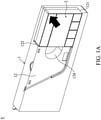
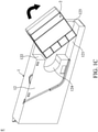
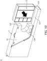
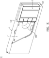
- Figs. 1A ⁇ 1E show the operations of an electronic device with a display interface of the embodiment of the invention.
- the electronic device E of the embodiment of the invention includes a device body 1 and a display module 2.
- the display module 2 can be slid and rotated relative to the device body 1.
- the display module 2 can be rotated between the first module orientation ( Fig. 1A ) and the second module orientation (Fig. IE). No matter the electronic device E is in a lying state or in a standing state, the user can easily read the information shown on the display module 2.
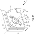
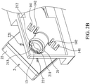
- Figs. 2A and 2B show the details of the electronic device of a first embodiment of the invention.
- the device body 1 includes a groove 11.
- the display module 2 is disposed on the device body 1.
- the display module 2 comprises a shaft 21.
- the shaft 21 is rotatably connected to the groove 11, and is adapted to be slid in the groove 11.
- the display module 2 pivots on the device body 1 via the shaft 21.
- An extension direction ⁇ of the groove 11 differs from an axis ⁇ of the shaft 21.
- the extension direction ⁇ of the groove 11 is perpendicular to the axis ⁇ of the shaft 21.
- the shaft 21 is slid between a first groove portion ( Fig. 2A ) and a second groove position ( Fig. 2B ) inside the groove 11.
- a first groove portion Fig. 2A
- a second groove position Fig. 2B
- the orientation of the display module 2 relative to the device body 1 is restricted.
- the display module 2 is adapted to be rotated relative to the device body 1 (As shown in Figs. 1B , 1C and ID).
- the device body 1 comprises a cover 12.
- the groove 11 is formed on the cover 12.
- the cover 12 comprises a first cover wall 121.
- the first cover wall 121 abuts the display module 2.
- the first cover wall 121 is separated from the display module 2 ( Figs. 1B , 1C and ID).
- the cover 12 comprises a receiving portion 123.
- the receiving portion 123 is located in a corner of the cover 12.
- the groove 11 is formed in the receiving portion 123.
- the display module 2 When the shaft 21 is in the first groove position ( Figs. 1A and IE), the display module 2 sufficiently located in the receiving portion 123.
- the shaft 21 When the shaft 21 is in the second groove position ( Figs. 1B , 1C an ID), at least a portion of the display module 2 is located outside the receiving portion 123.
- the cover 12 further comprises a second cover wall 122.
- the second cover wall 122 is perpendicular to the first cover wall 121.
- a wall notch 124 is formed on the second cover wall 122.
- the wall notch 124 corresponds to one side of the display module 2. Therefore, the finger of the user can insert into the wall notch 124 and push the display module 2.
- the shaft 21 is adapted to abut the inner wall of the groove 11, and is slid along the groove 11.
- the shaft 21 comprises a shaft restriction slot 213.
- the shaft restriction slot 213 comprises a first stopping wall 211 and a second stopping wall 212.
- the device body 1 comprises a device stopping protrusion 13.
- the device stopping protrusion 13 is inserted into the shaft restriction slot 213.
- the device stopping protrusion 13 abuts the first stopping wall 211.
- the device stopping protrusion 13 abuts the second abutting wall 212.
- the rotational range of the display module 2 is restricted.
- Fig. 2C shows a module wedging portion and a device wedging portion of the first embodiment of the invention.
- the display module 2 comprises a module body 22.
- the shaft 21 is connected to the module body 22.
- the module body 22 comprises at least one module wedging portion 221.
- the device body 1 comprises at least one device wedging portion 141.
- the module wedging portion 221 is wedged into the device wedging portion 141 to restrict the orientation of the display module 2.
- the module wedging portion 221 is separated from the device wedging portion 141.
- the device wedging portion 141 comprises a wedging arm (141), and the extension direction of the wedging arm (141) is parallel to the extension direction ⁇ of the groove 11.
- the device body 1 comprises a plurality of device wedging portions 141, and the device wedging portions 141 are disposed on both sides of the groove 11.
- the shaft 21 further comprises a plurality of shaft restriction notches 217.
- the device body 1 comprises at least one device restriction hook 142.
- the device restriction hook 142 wedges one of the shaft restriction notches 217.
- the device restriction hook 142 wedges another shaft restriction notches 217, and the orientation of the display module 2 is therefore restricted.
- the shaft 21' comprises a first shaft stopping protrusion 214.
- the device body 1' comprises a device restriction slot 15.
- the device restriction slot 15 comprises a third stopping wall 151 and a fourth stopping wall 152.
- the shaft 21' comprises a plurality of flexible fasteners 215.
- the flexible fasteners 215 are arranged in an annular manner.
- the flexible fasteners 215 are wedged into the device body 1'.
- the groove 11' comprises a first groove area 111, a second groove area 112 and a waist area 113.
- the waist area 113 is located between the first groove area 111 and the second groove area 112.
- the width of the waist area 113 is smaller than the width of the first groove area 111.
- the width of the waist area 113 is smaller than the width of the second groove area 112.
- the shaft 21' When the shaft 21' is in the second groove position ( Fig. 3B ), the shaft 21' is in the second groove area 112. Utilizing the flexible fasteners 215 and the waist area 113, the shaft 21' can stably stay in the first groove area 111 or the second groove area 112.
- the device body comprises at least one restriction slot 161.
- the shaft 21' comprises a second shaft stopping protrusion 216.
- the second shaft stopping protrusion 216 wedges one of the restriction slot 161 to restrict the orientation of the display module 2.
- the electronic device can be an uninterruptible power system
- the display module shows the power-capacitance information and voltage information.
- the display module can be rotated relative to the device body.
- the shaft of the embodiment of the invention has simpler structure and occupies smaller space.
- the display module is coupled to a mainboard of the electronic device via a cable. The length of the cable can be reduced, and the cable is prevented from being unexpectedly detached from the display module.
Landscapes
- Engineering & Computer Science (AREA)
- Theoretical Computer Science (AREA)
- Microelectronics & Electronic Packaging (AREA)
- Physics & Mathematics (AREA)
- Computer Hardware Design (AREA)
- Human Computer Interaction (AREA)
- General Engineering & Computer Science (AREA)
- General Physics & Mathematics (AREA)
- Mathematical Physics (AREA)
- Devices For Indicating Variable Information By Combining Individual Elements (AREA)
- Pivots And Pivotal Connections (AREA)
Abstract
Description
- This Application claims priority of
China Patent Application No. 202010776035.X, filed on Aug. 5, 2020 - The present invention relates to an electronic device, and in particular to an electronic device with a display interface.
- A conventional uninterruptible power system has a display module. The display module shows power-capacitance information and voltage information. Commonly, the display module is affixed to the uninterruptible power system. When the orientation of the uninterruptible power system is changed (for example, changed from the standing state to a lying state), the orientation of the display module changes (for example, it changes by 90 degrees), and it is inconvenient for the user to read the power-capacitance information and the voltage information.
- Conventionally, to allow the display module to rotate relative to the uninterruptible power system, a complex pivoting mechanism is provided. The conventional pivoting mechanism takes up space inside the uninterruptible power system, and needs a longer cable to connect the display module with the mainboard of the uninterruptible power system.
- Embodiments of the invention are provided to address the aforementioned difficulty.
- In one embodiment, an electronic device with a display interface is provided. The electronic device includes a device body and a display module. The device body includes a groove. The display module is disposed on the device body, wherein the display module comprises a shaft, the shaft is rotatably connected to the groove and is adapted to be slid in the groove, and the extension direction of the groove differs from the axis of the shaft.
- In one embodiment, the extension direction of the groove is perpendicular to the axis of the shaft.
- In one embodiment, the shaft is slid between a first groove portion and a second groove position inside the groove, and when the shaft is in the first groove position, the orientation of the display module relative to the device body is restricted, and when the shaft is in the second groove position, the display module is adapted to be rotated relative to the device body.
- In one embodiment, the device body comprises a cover, the groove is formed on the cover, the cover comprises a first cover wall, and when the shaft is in the first groove position, the first cover wall abuts the display module, and when the shaft is in the second groove portion, the first cover wall is separated from the display module.
- In one embodiment, the cover comprises a receiving portion, the receiving portion is located in a corner of the cover, a groove is formed in the receiving portion, and when the shaft is in the first groove position, the display module is sufficiently located in the receiving portion, and when the shaft is in the second groove position, at least a portion of the display module is located outside the receiving portion.
- In one embodiment, the cover further comprises a second cover wall, the second cover wall is perpendicular to the first cover wall, a wall notch is formed on the second cover wall, and the wall notch corresponds to one side of the display module.
- In one embodiment, the shaft is adapted to abut the inner wall of the groove.
- In one embodiment, the shaft comprises a shaft restriction slot, the shaft restriction slot comprises a first stopping wall and a second stopping wall, the device body comprises a device stopping protrusion, and when the shaft is in the second groove position, the device stopping protrusion is inserted into the shaft restriction slot, and when the shaft is in the second groove position and the display module is in the first module orientation, the device stopping protrusion abuts the first stopping wall, and when the shaft is in the second groove position and the display module is in the second module orientation, the device stopping protrusion abuts the second abutting wall.
- In one embodiment, the display module comprises a module body, the shaft is connected to the module body, the module body comprises at least one module wedging portion, the device body comprises at least one device wedging portion, and when the shaft is in the first groove position in the groove, the module wedging portion is wedged into the device wedging portion, and when the shaft is in the second groove position in the groove, the module wedging portion is separated from the device wedging portion.
- In one embodiment, the device wedging portion comprises a wedging arm, and the extension direction of the wedging arm is parallel to the extension direction of the groove.
- In one embodiment, the device body comprises a plurality of device wedging portions, and the device wedging portions are disposed on both sides of the groove.
- In one embodiment, the shaft comprises a first shaft stopping protrusion, the device body comprises a device restriction slot, the device restriction slot comprises a third stopping wall and a fourth stopping wall, and when the shaft is in the second groove position, the first shaft stopping protrusion is inserted into the device restriction slot, and when the shaft is in the second groove position, and the display module is in the first module orientation, the first shaft stopping protrusion abuts the third stopping wall, and when the shaft is in the second groove position, and the display module is in the second module orientation, the first shaft stopping protrusion abuts the fourth stopping wall.
- In one embodiment, the shaft comprises a plurality of flexible fasteners, the flexible fasteners are arranged in an annular manner, the flexible fasteners are wedged into the device body, the groove comprises a first groove area, a second groove area and a waist area, the waist area is located between the first groove area and the second groove area, the width of the waist area is smaller than the width of the first groove area, the width of the waist area is smaller than the width of the second groove area, and when the shaft is in the first groove position, the shaft is in the first groove area, and when the shaft is in the second groove position, the shaft is in the second groove area.
- In one embodiment, the device body comprises at least one restriction slot, the shaft comprises a second shaft stopping protrusion, and when the shaft is in the first groove position, the second shaft stopping protrusion wedges one of the restriction slots to restrict the orientation of the display module.
- In one embodiment, the display module shows the power-capacitance information and voltage information.
- Utilizing the electronic device of the embodiment of the invention, the display module can be rotated relative to the device body. The shaft of the embodiment of the invention has simpler structure and occupies smaller space. The display module is coupled to a mainboard of the electronic device via a cable. The length of the cable can be reduced, and the cable is prevented from being unexpectedly detached from the display module.
- A detailed description is given in the following embodiments with reference to the accompanying drawings.
- The present invention can be more fully understood by reading the subsequent detailed description and examples with references made to the accompanying drawings, wherein:
-
Figs. 1A∼1E show the operations of an electronic device with a display interface of the embodiment of the invention; -
Fig. 2A shows the details of the electronic device of a first embodiment of the invention, wherein a shaft is in a first groove position of a groove; -
Fig. 2B shows the details of the electronic device of the first embodiment of the invention, wherein the shaft is in a second groove position of the groove; -
Fig. 2C shows a module wedging portion and a device wedging portion of the first embodiment of the invention; -
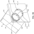
Fig. 3A shows the details of the electronic device of a second embodiment of the invention, wherein the shaft is in the first groove position of the groove; and -
Fig. 3B shows the details of the electronic device of the second embodiment of the invention, wherein the shaft is in the second groove position of the groove. - The following description is of the best-contemplated mode of carrying out the invention. This description is made for the purpose of illustrating the general principles of the invention and should not be taken in a limiting sense. The scope of the invention is best determined by reference to the appended claims.
-
Figs. 1A∼1E show the operations of an electronic device with a display interface of the embodiment of the invention. With reference toFigs. 1A∼1E , the electronic device E of the embodiment of the invention includes adevice body 1 and adisplay module 2. Thedisplay module 2 can be slid and rotated relative to thedevice body 1. Thedisplay module 2 can be rotated between the first module orientation (Fig. 1A ) and the second module orientation (Fig. IE). No matter the electronic device E is in a lying state or in a standing state, the user can easily read the information shown on thedisplay module 2. -
Figs. 2A and2B show the details of the electronic device of a first embodiment of the invention. With reference toFigs. 2A and2B , in one embodiment, thedevice body 1 includes agroove 11. Thedisplay module 2 is disposed on thedevice body 1. Thedisplay module 2 comprises ashaft 21. Theshaft 21 is rotatably connected to thegroove 11, and is adapted to be slid in thegroove 11. Thedisplay module 2 pivots on thedevice body 1 via theshaft 21. An extension direction α of thegroove 11 differs from an axis β of theshaft 21. - In one embodiment, the extension direction αof the
groove 11 is perpendicular to the axis β of theshaft 21. - With reference to
Figs. 2A and2B , in one embodiment, theshaft 21 is slid between a first groove portion (Fig. 2A ) and a second groove position (Fig. 2B ) inside thegroove 11. When theshaft 21 is in the first groove position (Fig. 2A ), the orientation of thedisplay module 2 relative to thedevice body 1 is restricted. When theshaft 21 is in the second groove position (Fig. 2B ), thedisplay module 2 is adapted to be rotated relative to the device body 1 (As shown inFigs. 1B ,1C and ID). - With reference to
Figs. 1A∼1E , in one embodiment, thedevice body 1 comprises acover 12. Thegroove 11 is formed on thecover 12. Thecover 12 comprises afirst cover wall 121. When theshaft 21 is in the first groove position (Figs. 1A and IE), thefirst cover wall 121 abuts thedisplay module 2. When theshaft 21 is in the second groove portion, thefirst cover wall 121 is separated from the display module 2 (Figs. 1B ,1C and ID). - With reference to
Figs. 1A∼1E , in one embodiment, thecover 12 comprises a receivingportion 123. The receivingportion 123 is located in a corner of thecover 12. Thegroove 11 is formed in the receivingportion 123. When theshaft 21 is in the first groove position (Figs. 1A and IE), thedisplay module 2 sufficiently located in the receivingportion 123. When theshaft 21 is in the second groove position (Figs. 1B ,1C an ID), at least a portion of thedisplay module 2 is located outside the receivingportion 123. - With reference to
Figs. 1A∼1E , in one embodiment, thecover 12 further comprises asecond cover wall 122. Thesecond cover wall 122 is perpendicular to thefirst cover wall 121. Awall notch 124 is formed on thesecond cover wall 122. Thewall notch 124 corresponds to one side of thedisplay module 2. Therefore, the finger of the user can insert into thewall notch 124 and push thedisplay module 2. - With reference to
Figs. 2A and2B , in one embodiment, theshaft 21 is adapted to abut the inner wall of thegroove 11, and is slid along thegroove 11. - With reference to
Figs. 2A and2B , in one embodiment, theshaft 21 comprises ashaft restriction slot 213. Theshaft restriction slot 213 comprises a first stoppingwall 211 and a second stoppingwall 212. Thedevice body 1 comprises adevice stopping protrusion 13. When theshaft 21 is in the second groove position, thedevice stopping protrusion 13 is inserted into theshaft restriction slot 213. When theshaft 21 is in the second groove position and thedisplay module 2 is in the first module orientation, thedevice stopping protrusion 13 abuts the first stoppingwall 211. When theshaft 21 is in the second groove position and thedisplay module 2 is in the second module orientation, thedevice stopping protrusion 13 abuts the secondabutting wall 212. In the embodiment of the invention, the rotational range of thedisplay module 2 is restricted. -
Fig. 2C shows a module wedging portion and a device wedging portion of the first embodiment of the invention. With reference toFigs. 2A ,2B and2C , in one embodiment, thedisplay module 2 comprises amodule body 22. Theshaft 21 is connected to themodule body 22. Themodule body 22 comprises at least onemodule wedging portion 221. Thedevice body 1 comprises at least onedevice wedging portion 141. When theshaft 21 is in the first groove position in thegroove 11, themodule wedging portion 221 is wedged into thedevice wedging portion 141 to restrict the orientation of thedisplay module 2. When theshaft 21 is in the second groove position in thegroove 11, themodule wedging portion 221 is separated from thedevice wedging portion 141. - With reference to
Figs. 2A ,2B and2C , in one embodiment, thedevice wedging portion 141 comprises a wedging arm (141), and the extension direction of the wedging arm (141) is parallel to the extension direction α of thegroove 11. - With reference to
Figs. 2A ,2B and2C , in one embodiment, thedevice body 1 comprises a plurality ofdevice wedging portions 141, and thedevice wedging portions 141 are disposed on both sides of thegroove 11. - In one embodiment, the
shaft 21 further comprises a plurality ofshaft restriction notches 217. Thedevice body 1 comprises at least onedevice restriction hook 142. When theshaft 21 is in the first groove position in thegroove 11 and thedisplay module 2 is in the first module orientation, thedevice restriction hook 142 wedges one of theshaft restriction notches 217. When theshaft 21 is in the first groove position in thegroove 11 and thedisplay module 2 is in the second module orientation, thedevice restriction hook 142 wedges anothershaft restriction notches 217, and the orientation of thedisplay module 2 is therefore restricted. -
Figs. 3A and3B show the details of the electronic device of a second embodiment of the invention. With reference toFigs. 3A and3B , in one embodiment, the shaft 21' comprises a firstshaft stopping protrusion 214. The device body 1' comprises adevice restriction slot 15. Thedevice restriction slot 15 comprises a third stoppingwall 151 and a fourth stoppingwall 152. When the shaft 21' is in the second groove position (Fig. 3B ), the firstshaft stopping protrusion 214 is inserted into thedevice restriction slot 15. When the shaft 21' is in the second groove position, and thedisplay module 2' is in the first module orientation, the firstshaft stopping protrusion 214 abuts the third stoppingwall 151. When the shaft 21' is in the second groove position, and thedisplay module 2 is in the second module orientation, the firstshaft stopping protrusion 214 abuts the fourth stoppingwall 152. Utilizing the embodiment of the invention, the orientation of thedisplay module 2 is therefore restricted. - With reference to
Figs. 3A and3B , in one embodiment, the shaft 21' comprises a plurality offlexible fasteners 215. Theflexible fasteners 215 are arranged in an annular manner. Theflexible fasteners 215 are wedged into the device body 1'. Thegroove 11' comprises afirst groove area 111, asecond groove area 112 and awaist area 113. Thewaist area 113 is located between thefirst groove area 111 and thesecond groove area 112. The width of thewaist area 113 is smaller than the width of thefirst groove area 111. The width of thewaist area 113 is smaller than the width of thesecond groove area 112. When the shaft 21' is in the first groove position (Fig. 3A ), the shaft 21' is in thefirst groove area 111. When the shaft 21' is in the second groove position (Fig. 3B ), the shaft 21' is in thesecond groove area 112. Utilizing theflexible fasteners 215 and thewaist area 113, the shaft 21' can stably stay in thefirst groove area 111 or thesecond groove area 112. - With reference to
Figs. 3A and3B , in one embodiment, the device body comprises at least onerestriction slot 161. The shaft 21' comprises a secondshaft stopping protrusion 216. When the shaft 21' is in the first groove position, the secondshaft stopping protrusion 216 wedges one of therestriction slot 161 to restrict the orientation of thedisplay module 2. - In one embodiment, the electronic device can be an uninterruptible power system, and the display module shows the power-capacitance information and voltage information.
- Utilizing the electronic device of the embodiment of the invention, the display module can be rotated relative to the device body. The shaft of the embodiment of the invention has simpler structure and occupies smaller space. The display module is coupled to a mainboard of the electronic device via a cable. The length of the cable can be reduced, and the cable is prevented from being unexpectedly detached from the display module.
- Use of ordinal terms such as "first", "second", "third", etc., in the claims to modify a claim element does not by itself connote any priority, precedence, or order of one claim element over another or the temporal order in which acts of a method are performed, but are used merely as labels to distinguish one claim element having a certain name from another element having the same name (but for use of the ordinal term).
- While the invention has been described by way of example and in terms of the preferred embodiments, it should be understood that the invention is not limited to the disclosed embodiments. On the contrary, it is intended to cover various modifications and similar arrangements (as would be apparent to those skilled in the art). Therefore, the scope of the appended claims should be accorded the broadest interpretation so as to encompass all such modifications and similar arrangements.
Claims (12)
- An electronic device (E) with a display interface, comprising:a device body (1), comprising a groove (11);a display module (2), disposed on the device body, wherein the display module comprises a shaft (21), the shaft is rotatably connected to the groove, and is adapted to be slid in the groove, and an extension direction (α) of the groove differs from an axis (β) of the shaft,wherein the extension direction (α) of the groove (11) is perpendicular to the axis (β) of the shaft (21),wherein the shaft (21) is slid between a first groove portion and a second groove position inside the groove (11), and when the shaft (21) is in the first groove position, an orientation of the display module (2) relative to the device body (1) is restricted, and when the shaft (21) is in the second groove position, the display module (2) is adapted to be rotated relative to the device body (1),wherein the device body (1) comprises a cover (12), the groove (11) is formed on the cover, the cover comprises a first cover wall (121), and when the shaft is in the first groove position, the first cover wall abuts the display module (2), and when the shaft is in the second groove portion, the first cover wall is separated from the display module.
- The electronic device (E) as claimed in claim 1, wherein the cover (12) comprises a receiving portion (123), the receiving portion is located in a corner of the cover, the groove is formed in the receiving portion, and when the shaft (21) is in the first groove position, the display module (2) is sufficiently located in the receiving portion, and when the shaft is in the second groove position, at least a portion of the display module is located outside the receiving portion.
- The electronic device (E) as claimed in claim 2, wherein the cover (12) further comprises a second cover wall (122), the second cover wall is perpendicular to the first cover wall (121), a wall notch (124) is formed on the second cover wall, and the wall notch corresponds to one side of the display module.
- The electronic device (E) as claimed in claim 1, wherein the shaft (21) is adapted to abut an inner wall of the groove (11).
- The electronic device (E) as claimed in claim 1, wherein the shaft (21) comprises a shaft restriction slot (213), the shaft restriction slot comprises a first stopping wall (211) and a second stopping wall (211), the device body (1) comprises a device stopping protrusion (13), and when the shaft is in the second groove position, the device stopping protrusion is inserted into the shaft restriction slot, and when the shaft is in the second groove position and the display module is in a first module orientation, the device stopping protrusion abuts the first stopping wall, and when the shaft is in the second groove position and the display module is in a second module orientation, the device stopping protrusion abuts the second abutting wall.
- The electronic device (E) as claimed in claim 1, wherein the display module (2) comprises a module body (22), the shaft (21) is connected to the module body, the module body comprises at least one module wedging portion (221), the device body comprises at least one device wedging portion (141), and when the shaft is in the first groove position in the groove, the module wedging portion is wedged into the device wedging portion, and when the shaft is in the second groove position in the groove, the module wedging portion is separated from the device wedging portion.
- The electronic device (E) as claimed in claim 6, wherein the device wedging portion (141) comprises a wedging arm, and an extension direction of the wedging arm is parallel to the extension direction (α) of the groove (11).
- The electronic device (E) as claimed in claim 7, wherein the device body (1) comprises a plurality of device wedging portions (141), and the device wedging portions are disposed on both sides of the groove (11).
- The electronic device (E) as claimed in claim 1, wherein the shaft (21; 21') comprises a first shaft stopping protrusion (214), the device body (1') comprises a device restriction slot (15), the device restriction slot comprises a third stopping wall (151) and a fourth stopping wall (152), and when the shaft (21') is in the second groove position, the first shaft stopping protrusion is inserted into the device restriction slot, and when the shaft is in the second groove position, and the display module is in the first module orientation, the first shaft stopping protrusion abuts the third stopping wall, and when the shaft is in the second groove position, and the display module is in the second module orientation, the first shaft stopping protrusion abuts the fourth stopping wall.
- An electronic device (E) with a display interface, comprising:a device body (1), comprising a groove (11);a display module (2), disposed on the device body, wherein the display module comprises a shaft (21), the shaft is rotatably connected to the groove, and is adapted to be slid in the groove, and an extension direction (α) of the groove differs from an axis (β) of the shaft,wherein the extension direction (α) of the groove (11) is perpendicular to the axis (β) of the shaft (21),wherein the shaft (21) is slid between a first groove portion and a second groove position inside the groove (11), and when the shaft (21) is in the first groove position, an orientation of the display module (2) relative to the device body (1) is restricted, and when the shaft (21) is in the second groove position, the display module (2) is adapted to be rotated relative to the device body (1),wherein the shaft (21') comprises a plurality of flexible fasteners (215), the flexible fasteners are arranged in an annular manner, the flexible fasteners are wedged into the device body (1'), the groove (11') comprises a first groove area (111), a second groove area (112) and a waist area (113), the waist area is located between the first groove area and the second groove area, a width of the waist area is smaller than a width of the first groove area, the width of the waist area (113) is smaller than a width of the second groove area (111), and when the shaft is in the first groove position, the shaft is in the first groove area, and when the shaft is in the second groove position, the shaft is in the second groove area.
- The electronic device as claimed in claim 10, wherein the device body (1; 1') comprises at least one restriction slot (161), the shaft (21') comprises a second shaft stopping protrusion (216), and when the shaft is in the first groove position, the second shaft stopping protrusion wedges one of the restriction slots (161) to restrict the orientation of the display module (2).
- The electronic device as claimed in claim 10, wherein the display module (2) shows power-capacitance information and voltage information.
Applications Claiming Priority (1)
| Application Number | Priority Date | Filing Date | Title |
|---|---|---|---|
| CN202010776035.XA CN114071908B (en) | 2020-08-05 | 2020-08-05 | Electronic device with display interface |
Publications (3)
| Publication Number | Publication Date |
|---|---|
| EP3971678A1 true EP3971678A1 (en) | 2022-03-23 |
| EP3971678B1 EP3971678B1 (en) | 2023-07-12 |
| EP3971678C0 EP3971678C0 (en) | 2023-07-12 |
Family
ID=77179870
Family Applications (1)
| Application Number | Title | Priority Date | Filing Date |
|---|---|---|---|
| EP21185343.7A Active EP3971678B1 (en) | 2020-08-05 | 2021-07-13 | Electronic device with rotating display interface |
Country Status (4)
| Country | Link |
|---|---|
| US (1) | US11483939B2 (en) |
| EP (1) | EP3971678B1 (en) |
| JP (2) | JP7284217B2 (en) |
| CN (1) | CN114071908B (en) |
Citations (3)
| Publication number | Priority date | Publication date | Assignee | Title |
|---|---|---|---|---|
| US6522529B1 (en) * | 2000-05-22 | 2003-02-18 | Vivek R. Huilgol | Rotatable computer display apparatus and method |
| CN103200794A (en) * | 2012-01-05 | 2013-07-10 | 伊顿制造(格拉斯哥)有限合伙莫尔日分支机构 | Display box rotary component |
| US8611074B2 (en) * | 2011-08-04 | 2013-12-17 | Schneider Electric It Corporation | User interface mounting module and method to mount a user interface on a UPS |
Family Cites Families (25)
| Publication number | Priority date | Publication date | Assignee | Title |
|---|---|---|---|---|
| JPS486471U (en) * | 1971-06-04 | 1973-01-24 | ||
| US4731030A (en) * | 1987-01-09 | 1988-03-15 | Unisys Corporation | Tilt and swivel assembly for terminal monitor |
| JPH04104325U (en) * | 1991-02-21 | 1992-09-08 | 日本電気エンジニアリング株式会社 | Vertical flat display mounting mechanism |
| US5708561A (en) * | 1996-08-13 | 1998-01-13 | Vivek R. Huilgol | Portable computer having display slidably and rotatably mounted for movement between landscape and portrait orientation and to open and close speaker ports |
| TW321414U (en) * | 1997-05-07 | 1997-11-21 | Amtran Technology Co Ltd | Pivot-rotation device of flat-display panel |
| TW378830U (en) * | 1997-08-09 | 2000-01-01 | Mitac Int Corp | Sliding and revolving structure for LCD screens |
| TW444893U (en) * | 1998-08-26 | 2001-07-01 | Mitac Int Corp | Computer with the continuous balance display |
| US7092246B2 (en) * | 2003-11-18 | 2006-08-15 | Kabushiki Kaisha Toshiba | Apparatus for connecting a display to a body case of an electronic device |
| US7054145B2 (en) * | 2003-11-18 | 2006-05-30 | Kabushiki Kaisha Toshiba | Mechanism for adjusting a display |
| US7042711B2 (en) * | 2003-11-18 | 2006-05-09 | Kabushiki Kaisha Toshiba | Multi-functional electronic device with a continuously accessible pointing device |
| US7082028B2 (en) * | 2004-07-08 | 2006-07-25 | Swivel It, Inc. | Rotatable computer display apparatus and method |
| KR100663542B1 (en) | 2004-07-30 | 2007-01-02 | 삼성전자주식회사 | Sliding swing device for portable device |
| TWI278216B (en) * | 2005-11-03 | 2007-04-01 | Benq Corp | Mobile device |
| FR2894789B1 (en) * | 2005-12-20 | 2008-02-22 | Valeo Securite Habitacle Sas | DISPOSITION OF POSITIONING AND MAINTAINING A SECURITY KEY |
| KR100998937B1 (en) * | 2007-07-30 | 2010-12-09 | 한 상 이 | Sliding and Rotation Complex Mechanism and Portable Electronic Devices |
| US8500467B2 (en) * | 2007-10-30 | 2013-08-06 | Super Talent Electronics, Inc. | Flash drive with swivel cover |
| JP5448143B2 (en) | 2009-01-23 | 2014-03-19 | Necカシオモバイルコミュニケーションズ株式会社 | Rotating hinge and portable device |
| JP5313802B2 (en) | 2009-07-31 | 2013-10-09 | 加藤電機株式会社 | Opening / closing device for portable device and portable device using this opening / closing device |
| CN102252017A (en) * | 2010-05-20 | 2011-11-23 | 深圳富泰宏精密工业有限公司 | Rotating mechanism and electronic device with the rotating mechanism |
| US8693188B2 (en) * | 2011-05-24 | 2014-04-08 | Blackberry Limited | Pivotable display guide mechanism for an electronic mobile device |
| TWI462683B (en) * | 2012-02-01 | 2014-11-21 | Wistron Corp | Portable electronic device |
| TWI522539B (en) * | 2013-08-22 | 2016-02-21 | 宏碁股份有限公司 | Electronic device |
| WO2015045131A1 (en) | 2013-09-27 | 2015-04-02 | 富士通株式会社 | Electronic apparatus and hinge unit |
| US10335147B2 (en) * | 2014-06-25 | 2019-07-02 | Ethicon Llc | Method of using lockout features for surgical stapler cartridge |
| TWI760618B (en) * | 2018-06-11 | 2022-04-11 | 仁寶電腦工業股份有限公司 | Electronic device |
-
2020
- 2020-08-05 CN CN202010776035.XA patent/CN114071908B/en active Active
-
2021
- 2021-03-19 US US17/207,115 patent/US11483939B2/en active Active
- 2021-07-13 EP EP21185343.7A patent/EP3971678B1/en active Active
- 2021-07-27 JP JP2021122447A patent/JP7284217B2/en active Active
-
2023
- 2023-04-06 JP JP2023061858A patent/JP7519494B2/en active Active
Patent Citations (3)
| Publication number | Priority date | Publication date | Assignee | Title |
|---|---|---|---|---|
| US6522529B1 (en) * | 2000-05-22 | 2003-02-18 | Vivek R. Huilgol | Rotatable computer display apparatus and method |
| US8611074B2 (en) * | 2011-08-04 | 2013-12-17 | Schneider Electric It Corporation | User interface mounting module and method to mount a user interface on a UPS |
| CN103200794A (en) * | 2012-01-05 | 2013-07-10 | 伊顿制造(格拉斯哥)有限合伙莫尔日分支机构 | Display box rotary component |
Also Published As
| Publication number | Publication date |
|---|---|
| US11483939B2 (en) | 2022-10-25 |
| EP3971678B1 (en) | 2023-07-12 |
| CN114071908A (en) | 2022-02-18 |
| CN114071908B (en) | 2023-06-23 |
| JP2023090728A (en) | 2023-06-29 |
| JP2022031166A (en) | 2022-02-18 |
| JP7284217B2 (en) | 2023-05-30 |
| EP3971678C0 (en) | 2023-07-12 |
| US20220046812A1 (en) | 2022-02-10 |
| JP7519494B2 (en) | 2024-07-19 |
Similar Documents
| Publication | Publication Date | Title |
|---|---|---|
| US11442506B1 (en) | External display module | |
| US6301098B1 (en) | Book-shaped information terminal | |
| US10788854B1 (en) | Clamshell electronic device | |
| US7092246B2 (en) | Apparatus for connecting a display to a body case of an electronic device | |
| CN105706019B (en) | Flexible hinges for computing devices | |
| US6196850B1 (en) | Rotatable docking station for an electronic device | |
| US20240098164A1 (en) | Rotation Mechanism and Foldable Terminal | |
| US20040042159A1 (en) | Attachable/detachable keyboard apparatus of portable computer system | |
| US20200249730A1 (en) | Electronic device with external image-capturing module | |
| US9215818B2 (en) | Electronic device and hinge structure thereof | |
| US20040202858A1 (en) | Electronic device protective cover equipped with expansion functions | |
| US20130229393A1 (en) | Instrument-activated sub-surface computer buttons and system and method incorporating same | |
| US11382226B2 (en) | Electronic device and housing structure and locking module thereof | |
| EP2239928B1 (en) | Portable electronic device | |
| US20020080567A1 (en) | Hard case for handheld computer system | |
| EP4195631A1 (en) | Rotation mechanism, support device, and electronic apparatus | |
| US8654247B2 (en) | Image-capturing device and electronic equipment having the same | |
| US11483939B2 (en) | Electronic device with display interface | |
| EP2395410A2 (en) | Computer system and docking station thereof | |
| JP2708011B2 (en) | Portable information equipment | |
| US6208509B1 (en) | Portable computer having access door | |
| CN113898661A (en) | Rotary shaft device and electronic equipment | |
| US11853130B2 (en) | Electronic device and linked hinge mechanism thereof | |
| TWI743924B (en) | Electronic device with a display interface | |
| US6817588B2 (en) | Port replicator and resilient piece used therein |
Legal Events
| Date | Code | Title | Description |
|---|---|---|---|
| PUAI | Public reference made under article 153(3) epc to a published international application that has entered the european phase |
Free format text: ORIGINAL CODE: 0009012 |
|
| STAA | Information on the status of an ep patent application or granted ep patent |
Free format text: STATUS: THE APPLICATION HAS BEEN PUBLISHED |
|
| AK | Designated contracting states |
Kind code of ref document: A1 Designated state(s): AL AT BE BG CH CY CZ DE DK EE ES FI FR GB GR HR HU IE IS IT LI LT LU LV MC MK MT NL NO PL PT RO RS SE SI SK SM TR |
|
| STAA | Information on the status of an ep patent application or granted ep patent |
Free format text: STATUS: REQUEST FOR EXAMINATION WAS MADE |
|
| 17P | Request for examination filed |
Effective date: 20220704 |
|
| RBV | Designated contracting states (corrected) |
Designated state(s): AL AT BE BG CH CY CZ DE DK EE ES FI FR GB GR HR HU IE IS IT LI LT LU LV MC MK MT NL NO PL PT RO RS SE SI SK SM TR |
|
| GRAP | Despatch of communication of intention to grant a patent |
Free format text: ORIGINAL CODE: EPIDOSNIGR1 |
|
| STAA | Information on the status of an ep patent application or granted ep patent |
Free format text: STATUS: GRANT OF PATENT IS INTENDED |
|
| RIC1 | Information provided on ipc code assigned before grant |
Ipc: H04M 1/02 20060101ALN20230315BHEP Ipc: H05K 5/00 20060101ALI20230315BHEP Ipc: G06F 1/16 20060101AFI20230315BHEP |
|
| INTG | Intention to grant announced |
Effective date: 20230327 |
|
| RIC1 | Information provided on ipc code assigned before grant |
Ipc: H04M 1/02 20060101ALN20230317BHEP Ipc: H05K 5/00 20060101ALI20230317BHEP Ipc: G06F 1/16 20060101AFI20230317BHEP |
|
| RIN1 | Information on inventor provided before grant (corrected) |
Inventor name: YU, CHUN-HSIEN Inventor name: LI, YOU-LIN |
|
| GRAS | Grant fee paid |
Free format text: ORIGINAL CODE: EPIDOSNIGR3 |
|
| GRAA | (expected) grant |
Free format text: ORIGINAL CODE: 0009210 |
|
| STAA | Information on the status of an ep patent application or granted ep patent |
Free format text: STATUS: THE PATENT HAS BEEN GRANTED |
|
| AK | Designated contracting states |
Kind code of ref document: B1 Designated state(s): AL AT BE BG CH CY CZ DE DK EE ES FI FR GB GR HR HU IE IS IT LI LT LU LV MC MK MT NL NO PL PT RO RS SE SI SK SM TR |
|
| REG | Reference to a national code |
Ref country code: CH Ref legal event code: EP |
|
| REG | Reference to a national code |
Ref country code: IE Ref legal event code: FG4D |
|
| REG | Reference to a national code |
Ref country code: DE Ref legal event code: R096 Ref document number: 602021003382 Country of ref document: DE |
|
| U01 | Request for unitary effect filed |
Effective date: 20230718 |
|
| U07 | Unitary effect registered |
Designated state(s): AT BE BG DE DK EE FI FR IT LT LU LV MT NL PT SE SI Effective date: 20230724 |
|
| U20 | Renewal fee for the european patent with unitary effect paid |
Year of fee payment: 3 Effective date: 20230731 |
|
| REG | Reference to a national code |
Ref country code: LT Ref legal event code: MG9D |
|
| PG25 | Lapsed in a contracting state [announced via postgrant information from national office to epo] |
Ref country code: GR Free format text: LAPSE BECAUSE OF FAILURE TO SUBMIT A TRANSLATION OF THE DESCRIPTION OR TO PAY THE FEE WITHIN THE PRESCRIBED TIME-LIMIT Effective date: 20231013 |
|
| PG25 | Lapsed in a contracting state [announced via postgrant information from national office to epo] |
Ref country code: ES Free format text: LAPSE BECAUSE OF FAILURE TO SUBMIT A TRANSLATION OF THE DESCRIPTION OR TO PAY THE FEE WITHIN THE PRESCRIBED TIME-LIMIT Effective date: 20230712 |
|
| PG25 | Lapsed in a contracting state [announced via postgrant information from national office to epo] |
Ref country code: IS Free format text: LAPSE BECAUSE OF FAILURE TO SUBMIT A TRANSLATION OF THE DESCRIPTION OR TO PAY THE FEE WITHIN THE PRESCRIBED TIME-LIMIT Effective date: 20231112 |
|
| PG25 | Lapsed in a contracting state [announced via postgrant information from national office to epo] |
Ref country code: RS Free format text: LAPSE BECAUSE OF FAILURE TO SUBMIT A TRANSLATION OF THE DESCRIPTION OR TO PAY THE FEE WITHIN THE PRESCRIBED TIME-LIMIT Effective date: 20230712 Ref country code: NO Free format text: LAPSE BECAUSE OF FAILURE TO SUBMIT A TRANSLATION OF THE DESCRIPTION OR TO PAY THE FEE WITHIN THE PRESCRIBED TIME-LIMIT Effective date: 20231012 Ref country code: IS Free format text: LAPSE BECAUSE OF FAILURE TO SUBMIT A TRANSLATION OF THE DESCRIPTION OR TO PAY THE FEE WITHIN THE PRESCRIBED TIME-LIMIT Effective date: 20231112 Ref country code: HR Free format text: LAPSE BECAUSE OF FAILURE TO SUBMIT A TRANSLATION OF THE DESCRIPTION OR TO PAY THE FEE WITHIN THE PRESCRIBED TIME-LIMIT Effective date: 20230712 Ref country code: GR Free format text: LAPSE BECAUSE OF FAILURE TO SUBMIT A TRANSLATION OF THE DESCRIPTION OR TO PAY THE FEE WITHIN THE PRESCRIBED TIME-LIMIT Effective date: 20231013 Ref country code: ES Free format text: LAPSE BECAUSE OF FAILURE TO SUBMIT A TRANSLATION OF THE DESCRIPTION OR TO PAY THE FEE WITHIN THE PRESCRIBED TIME-LIMIT Effective date: 20230712 |
|
| PG25 | Lapsed in a contracting state [announced via postgrant information from national office to epo] |
Ref country code: PL Free format text: LAPSE BECAUSE OF FAILURE TO SUBMIT A TRANSLATION OF THE DESCRIPTION OR TO PAY THE FEE WITHIN THE PRESCRIBED TIME-LIMIT Effective date: 20230712 |
|
| REG | Reference to a national code |
Ref country code: DE Ref legal event code: R097 Ref document number: 602021003382 Country of ref document: DE |
|
| REG | Reference to a national code |
Ref country code: IE Ref legal event code: MM4A |
|
| PG25 | Lapsed in a contracting state [announced via postgrant information from national office to epo] |
Ref country code: SM Free format text: LAPSE BECAUSE OF FAILURE TO SUBMIT A TRANSLATION OF THE DESCRIPTION OR TO PAY THE FEE WITHIN THE PRESCRIBED TIME-LIMIT Effective date: 20230712 Ref country code: RO Free format text: LAPSE BECAUSE OF FAILURE TO SUBMIT A TRANSLATION OF THE DESCRIPTION OR TO PAY THE FEE WITHIN THE PRESCRIBED TIME-LIMIT Effective date: 20230712 Ref country code: CZ Free format text: LAPSE BECAUSE OF FAILURE TO SUBMIT A TRANSLATION OF THE DESCRIPTION OR TO PAY THE FEE WITHIN THE PRESCRIBED TIME-LIMIT Effective date: 20230712 Ref country code: SK Free format text: LAPSE BECAUSE OF FAILURE TO SUBMIT A TRANSLATION OF THE DESCRIPTION OR TO PAY THE FEE WITHIN THE PRESCRIBED TIME-LIMIT Effective date: 20230712 Ref country code: MC Free format text: LAPSE BECAUSE OF FAILURE TO SUBMIT A TRANSLATION OF THE DESCRIPTION OR TO PAY THE FEE WITHIN THE PRESCRIBED TIME-LIMIT Effective date: 20230712 |
|
| PLBE | No opposition filed within time limit |
Free format text: ORIGINAL CODE: 0009261 |
|
| STAA | Information on the status of an ep patent application or granted ep patent |
Free format text: STATUS: NO OPPOSITION FILED WITHIN TIME LIMIT |
|
| 26N | No opposition filed |
Effective date: 20240415 |
|
| PG25 | Lapsed in a contracting state [announced via postgrant information from national office to epo] |
Ref country code: IE Free format text: LAPSE BECAUSE OF NON-PAYMENT OF DUE FEES Effective date: 20230713 |
|
| U20 | Renewal fee for the european patent with unitary effect paid |
Year of fee payment: 4 Effective date: 20240605 |
|
| PG25 | Lapsed in a contracting state [announced via postgrant information from national office to epo] |
Ref country code: IE Free format text: LAPSE BECAUSE OF NON-PAYMENT OF DUE FEES Effective date: 20230713 |
|
| REG | Reference to a national code |
Ref country code: CH Ref legal event code: PL |
|
| PG25 | Lapsed in a contracting state [announced via postgrant information from national office to epo] |
Ref country code: CH Free format text: LAPSE BECAUSE OF NON-PAYMENT OF DUE FEES Effective date: 20240731 |
|
| PGFP | Annual fee paid to national office [announced via postgrant information from national office to epo] |
Ref country code: GB Payment date: 20250522 Year of fee payment: 5 |
|
| U20 | Renewal fee for the european patent with unitary effect paid |
Year of fee payment: 5 Effective date: 20250606 |
|
| PG25 | Lapsed in a contracting state [announced via postgrant information from national office to epo] |
Ref country code: CY Free format text: LAPSE BECAUSE OF FAILURE TO SUBMIT A TRANSLATION OF THE DESCRIPTION OR TO PAY THE FEE WITHIN THE PRESCRIBED TIME-LIMIT; INVALID AB INITIO Effective date: 20210713 |
|
| PG25 | Lapsed in a contracting state [announced via postgrant information from national office to epo] |
Ref country code: HU Free format text: LAPSE BECAUSE OF FAILURE TO SUBMIT A TRANSLATION OF THE DESCRIPTION OR TO PAY THE FEE WITHIN THE PRESCRIBED TIME-LIMIT; INVALID AB INITIO Effective date: 20210713 |
|
| PG25 | Lapsed in a contracting state [announced via postgrant information from national office to epo] |
Ref country code: TR Free format text: LAPSE BECAUSE OF FAILURE TO SUBMIT A TRANSLATION OF THE DESCRIPTION OR TO PAY THE FEE WITHIN THE PRESCRIBED TIME-LIMIT Effective date: 20230712 |