EP3971524A1 - Polygon lookup method - Google Patents
Polygon lookup method Download PDFInfo
- Publication number
- EP3971524A1 EP3971524A1 EP19932253.8A EP19932253A EP3971524A1 EP 3971524 A1 EP3971524 A1 EP 3971524A1 EP 19932253 A EP19932253 A EP 19932253A EP 3971524 A1 EP3971524 A1 EP 3971524A1
- Authority
- EP
- European Patent Office
- Prior art keywords
- information
- polygonal
- area
- unit
- temporospatial
- Prior art date
- Legal status (The legal status is an assumption and is not a legal conclusion. Google has not performed a legal analysis and makes no representation as to the accuracy of the status listed.)
- Granted
Links
Images


Classifications
-
- G—PHYSICS
- G01—MEASURING; TESTING
- G01C—MEASURING DISTANCES, LEVELS OR BEARINGS; SURVEYING; NAVIGATION; GYROSCOPIC INSTRUMENTS; PHOTOGRAMMETRY OR VIDEOGRAMMETRY
- G01C21/00—Navigation; Navigational instruments not provided for in groups G01C1/00 - G01C19/00
- G01C21/38—Electronic maps specially adapted for navigation; Updating thereof
- G01C21/3863—Structures of map data
- G01C21/3867—Geometry of map features, e.g. shape points, polygons or for simplified maps
-
- G—PHYSICS
- G01—MEASURING; TESTING
- G01C—MEASURING DISTANCES, LEVELS OR BEARINGS; SURVEYING; NAVIGATION; GYROSCOPIC INSTRUMENTS; PHOTOGRAMMETRY OR VIDEOGRAMMETRY
- G01C21/00—Navigation; Navigational instruments not provided for in groups G01C1/00 - G01C19/00
- G01C21/26—Navigation; Navigational instruments not provided for in groups G01C1/00 - G01C19/00 specially adapted for navigation in a road network
- G01C21/28—Navigation; Navigational instruments not provided for in groups G01C1/00 - G01C19/00 specially adapted for navigation in a road network with correlation of data from several navigational instruments
- G01C21/30—Map- or contour-matching
- G01C21/32—Structuring or formatting of map data
-
- G—PHYSICS
- G01—MEASURING; TESTING
- G01C—MEASURING DISTANCES, LEVELS OR BEARINGS; SURVEYING; NAVIGATION; GYROSCOPIC INSTRUMENTS; PHOTOGRAMMETRY OR VIDEOGRAMMETRY
- G01C21/00—Navigation; Navigational instruments not provided for in groups G01C1/00 - G01C19/00
- G01C21/38—Electronic maps specially adapted for navigation; Updating thereof
- G01C21/3804—Creation or updating of map data
- G01C21/3807—Creation or updating of map data characterised by the type of data
- G01C21/3815—Road data
-
- G—PHYSICS
- G06—COMPUTING OR CALCULATING; COUNTING
- G06F—ELECTRIC DIGITAL DATA PROCESSING
- G06F16/00—Information retrieval; Database structures therefor; File system structures therefor
- G06F16/50—Information retrieval; Database structures therefor; File system structures therefor of still image data
- G06F16/58—Retrieval characterised by using metadata, e.g. metadata not derived from the content or metadata generated manually
- G06F16/587—Retrieval characterised by using metadata, e.g. metadata not derived from the content or metadata generated manually using geographical or spatial information, e.g. location
Definitions
- the present invention relates to a polygon retrieving method.
- the map information is partitioned in rectangles (meshes) defined in advance and the temporospatial information of the automobile which is within an area designated with the rectangle is acquired in the related art.
- a technology for retrieving temporospatial information as a 1-dimensional bit string at a high speed is disclosed (see NPL 1).
- the present invention has been devised in view of the foregoing circumstances and an objective of the present invention is to perform retrieval of temporospatial information with high accuracy.
- a polygon retrieving method is a method performed by a polygon retrieving device including a storage unit.
- the polygon retrieving method includes: converting a polygonal area within a predetermined unit area on a map into polygonal information indicated using coordinates of vertexes of the polygonal area and storing the polygonal information in the storage unit in association with a unit area; specifying temporospatial information including positional information corresponding to coordinates within the predetermined unit area on the map; and extracting temporospatial information including positional information corresponding to coordinates inside a polygonal area indicated by the polygonal information associated with the unit area among the specified temporospatial information.
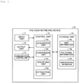
- FIG. 1 is a schematic diagram illustrating an overall configuration of a polygon retrieving device according to an embodiment.
- a polygon retrieving device 10 according to the embodiment is realized by a general-purpose computer such as a PC and includes an input unit 11, an output unit 12, a communication control unit 13, a storage unit 14, and a control unit 15.
- the input unit 11 is realized using an input device such as a keyboard or a mouse and inputs various kinds of instruction information such as a processing start to the control unit 15 in response to an input operation performed by an operator.
- the output unit 12 is realized by a display device such as a liquid crystal display, a printing device such as a printer, or the like. For example, a result of a polygon retrieving process to be described below is displayed on the output unit 12.
- the communication control unit 13 is realized by a network interface card (NIC) or the like and controls communication between the control unit 15 and an external device via an electrical communication line such as a local area network (LAN) or the Internet.
- NIC network interface card
- LAN local area network
- the communication control unit 13 controls communication between the control unit 15 and a management device or the like that manages map information, temporospatial information, and the like to be described below.
- the storage unit 14 is realized by a semiconductor memory element such as a random access memory (RAM) or a flash memory or a storage device such as a hard disk or an optical disc.
- the storage unit 14 stores a processing program for operating the polygon retrieving device 10, data used during execution of the processing program, and the like in advance or temporarily every time processing is performed.
- the storage unit 14 may be configured to communicate with the control unit 15 via the communication control unit 13.
- the storage unit 14 stores map information 14a, polygonal information 14b, temporospatial information 14c, and the like.
- the information is collected or generated and stored in the storage unit 14 earlier than a polygon retrieving process to be described below.
- an acquisition unit 15a to be described below collects the map information 14a from the management device or the like that manages the map information and stores the map information 14a in the storage unit 14.
- the acquisition unit 15a collects the temporospatial information 14c from the management device or the like that manages temporospatial information output from a sensor or the like and stores the temporospatial information 14c in the storage unit 14.
- a conversion unit 15b to be described below generates the polygonal information 14b and stores the polygonal information 14b in the storage unit 14.
- the information is stored in the storage unit 14 of the polygon retrieving device 10.
- the information may be collected or generated when a polygon retrieving process to be described below is performed.
- the map information 14a includes coordinates of a representative point of a polygonal area on a map.
- the map information 14a is information that includes coordinates of a central point of a polygonal area on a road and expresses the shape of the road on a map using a list of the coordinates of a road center, a road width, or the like.
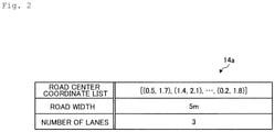
- Fig. 2 is a diagram illustrating a data structure of the map information 14a.
- the map information 14a indicating a shape of a road is exemplified.
- the map information 14a indicating the shape of the road includes a road center coordinate list, a road width, and the number of lanes.
- the road center coordinate list is a list of coordinates of a road center.
- An example illustrated in Fig. 2 expresses a shape of a road in which the coordinates of a central point of a road are (0.5, 1.7), (1.2, 1.4) and the like, a road width is 5 m, and the number of lanes of the road is 3.
- the polygonal information 14b is information indicating that the coordinates of vertexes of a polygonal area are used to express the polygonal area within a predetermined unit area on a map and is information generated by the conversion unit 15b to be described below and associated with the unit area.
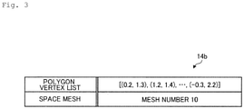
- Fig. 3 is a diagram illustrating a data structure of the polygonal information 14b.
- the polygon vertex list is a set of coordinates of vertexes of a polygonal area on a map.
- coordinates of vertexes of a polygonal area such as (0.2, 1.3), (1.2, 1.4) are enumerated.
- the space mesh is information for identifying the unit area of a rectangle defined on the map (hereinafter referred to as a mesh ID).
- mesh ID mesh ID
- mesh number 10 is exemplified.
- the temporospatial information 14c is information such as sensor values including positional information and temporal information and is, for example, information indicating a travel position of an automobile.
- the temporospatial information is a 1-dimensional bit string including positional information and temporal information.
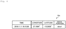
- Fig. 4 is a diagram illustrating a data structure of the temporospatial information 14c.
- the temporospatial information 14c exemplified in Fig. 4 includes a time serving as temporal information, longitude and latitude serving as positional information, and a data portion such as a sensor value.
- the temporospatial information 14c indicating a 1-dimensional bit string of a time "2019/1/1 10:15:30", a longitude "27.1984°", a latitude "-15.2958°”, and a data portion "data1" is exemplified.
- the control unit 15 is realized using a central processing unit (CPU) and the like and executes a processing program stored in a memory.
- the control unit 15 functions as an acquisition unit 15a, a conversion unit 15b, a specifying unit 15c, and an extraction unit 15d. All or some of the functional units may be mounted in different hardware.
- the control unit 15 may include other functional units.
- the acquisition unit 15a collects the map information 14a from the management device or the like that manages the map information via the input unit 11 or the communication control unit 13 and stores the map information 14a in the storage unit 14.
- the acquisition unit 15a collects the temporospatial information 14c from a management device or the like that manages the temporospatial information output from a sensor or the like via the input unit 11 or the communication control unit 13 and stores the temporospatial information 14c in the storage unit 14.
- the acquisition unit 15a may transmit such information to the conversion unit 15b or the specifying unit 15c to be described below without storing the information in the storage unit 14.
- the conversion unit 15b converts a polygonal area within the predetermined unit area on a map into the polygonal information 14b indicated using coordinates of vertexes of the polygonal area and stores the polygonal information in the storage unit 14 in association with the unit area.
- the conversion unit 15b converts the polygonal area into the polygonal information 14b indicating a polygonal area using the map information 14a including coordinates of a representative point of the polygonal area.
- Fig. 5 is a diagram illustrating a process of the conversion unit 15b.
- the conversion unit 15b specifies a central line of a road by connecting coordinates of the center of the road with reference to the map information 14a and specifies coordinates of vertexes of a polygonal area expressed on the road using a road width and the number of lanes.
- polygonal information expressed by coordinates of vertexes of four polygonal areas indicating four lanes on a road is exemplified.
- the conversion unit 15b converts the polygonal area within the unit area into the polygonal information 14b indicated by a set of the coordinates of the vertexes of the polygonal area for each rectangular unit area identified with a mesh ID defined on the map and stores the polygonal information 14b in the storage unit 14 in association with the mesh ID.
- the conversion unit 15b may transmit the polygonal information 14b to the extraction unit 15d to be described below without storing the polygonal information 14b in the storage unit 14.
- the specifying unit 15c specifies the temporospatial information 14c including the positional information corresponding to the coordinates within the predetermined area on the map. Specifically, the specifying unit 15c retrieves and specifies the temporospatial information 14c including the positional information corresponding to the coordinates within the unit area for each mesh ID.
- the extraction unit 15d extracts the temporospatial information 14c including the positional information corresponding to the coordinates inside the polygonal area indicated by the polygonal information 14b associated with the unit area among the temporospatial information 14c specified by the specifying unit 15c.
- the extraction unit 15d extracts the temporospatial information 14c corresponding to the inside of the polygonal area within the unit area among the temporospatial information 14c specified by the specifying unit 15c with reference to the polygonal information 14b for each mesh ID.
- the extraction unit 15d extracts the temporospatial information 14c including the positional information corresponding to the coordinates inside the polygonal area indicated by the polygonal information using the geometric algorithm information.
- the extraction unit 15d applies, for example, points-in-polygon (PIP) processing using a geometric algorithm library and determines whether the coordinates of the temporospatial information 14c on the map are inside the polygonal area indicated by the polygonal information.
- PIP points-in-polygon
- the extraction unit 15d outputs the extracted temporospatial information 14c to, for example, the output unit 12 or an application such as automated driving or route guidance.
- the user can further detect the temporospatial information inside the polygonal area among the temporospatial information within the rectangular unit area defined on the map with high accuracy.
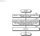
- Fig. 6 is a flowchart illustrating an order of the polygon retrieving process.
- the flowchart of Fig. 6 starts at, for example, a timing at which the user performs an input operation of giving a start instruction.
- the conversion unit 15b converts the polygonal area within the rectangular unit area identified with the mesh ID defined on the map into the polygonal information 14b indicated using the coordinates of the vertexes of the polygonal area.
- the conversion unit 15b converts the polygonal area into the polygonal information 14b indicating the polygonal area using the map information 14a including the coordinates of the representative point of the polygonal area.
- the conversion unit 15b stores the converted polygonal information 14b in the storage unit 14 in association with the mesh ID of the unit area.
- the specifying unit 15c specifies the temporospatial information 14c including the positional information corresponding to the coordinates within the predetermined unit area on the map (step S1). Specifically, for the temporospatial information 14c collected by the acquisition unit 15a, the specifying unit 15c retrieves and specifies the temporospatial information 14c including the positional information corresponding to the coordinates within the unit area for each mesh ID.
- the extraction unit 15d extracts the temporospatial information 14c including the positional information corresponding to the coordinates inside the polygonal area indicated by the polygonal information 14b associated with the unit area among the temporospatial information 14c specified by the specifying unit 15c (step S2). Specifically, the extraction unit 15d extracts the temporospatial information 14c inside the polygonal area within the unit area among the temporospatial information 14c specified by the specifying unit 15c with reference to the polygonal information 14b for each mesh ID.
- the extraction unit 15e outputs the extracted temporospatial information 14c to the output unit 12 or the application such as automated driving or route guidance (step S3) . Then, the series of the polygon retrieving process ends.
- the conversion unit 15b converts the polygonal area within the predetermined unit area on the map into the polygonal information 14b indicated using the coordinates of the vertexes of the polygonal area and stores the polygonal information 14b in the storage unit 14 in association with the unit area. Specifically, the conversion unit 15b converts the polygonal area into the polygonal information 14b indicating the polygonal area using the map information 14a including the coordinates of the representative point of the polygonal area.
- the specifying unit 15c specifies the temporospatial information 14c including the positional information corresponding to the coordinates within the predetermined unit area on the map.
- the extraction unit 15d extracts the temporospatial information 14c including the positional information corresponding to the coordinates inside the polygonal area indicated by the polygonal information 14b associated with the unit area among the specified temporospatial information 14c.
- the extraction unit 15d extracts the temporospatial information 14c including the positional information corresponding to the coordinates inside the polygonal area indicated by the polygonal information 14b using the geometric algorithm information.
- the polygon retrieving device 10 can further detect temporospatial information inside a polygonal area among temporospatial information within a rectangular unit area defined on a map.
- the polygon retrieving device 10 can detect an automobile which is on a specific road. In this way, through the polygon retrieving process of the polygon retrieving device 10, it is possible to retrieve temporospatial information with high accuracy.
- the temporospatial information 14c is a 1-dimensional bit string including positional information and temporal information. Thus, through the polygon retrieving process, it is possible to retrieve temporospatial information at a higher speed.
- the polygon retrieving device 10 can be mounted by installing a polygon retrieving program that performs the foregoing polygon retrieving process on a desired computer as package software or online software.
- a polygon retrieving program that performs the foregoing polygon retrieving process
- the information processing device mentioned here includes a desktop or notebook type personal computer.
- a mobile communication terminal such as a smartphone, a mobile phone, or a personal handyphone system (PHS) and a slate terminal such as a personal digital assistant (PDA) are included in the category of the information processing device.
- PDA personal digital assistant
- a function of the polygon retrieving device 10 may be mounted on a cloud server.
- FIG. 7 is a diagram illustrating an example of a computer that executes the polygon retrieving program.
- a computer 1000 includes, for example, a memory 1010, a CPU 1020, a hard disk drive interface 1030, a disk drive interface 1040, a serial port interface 1050, a video adapter 1060, and a network interface 1070. These units are connected by a bus 1080.
- the memory 1010 includes a read-only memory (ROM) 1011 and a RAM 1012.
- the ROM 1011 stores, for example, a boot program such as a basic input output system (BIOS).
- BIOS basic input output system
- the hard disk drive interface 1030 is connected to a hard disk drive 1031.
- the disk drive interface 1040 is connected to a disk drive 1041.
- a detachably mounted storage medium such as a magnetic disk or an optical disc is inserted into the disk drive 1041.
- a mouse 1051 and a keyboard 1052 are connected to the serial port interface 1050.
- a display 1061 is connected to the video adapter 1060.
- the hard disk drive 1031 stores, for example, an OS 1091, an application program 1092, a program module 1093, and program data 1094.
- the information described in the foregoing embodiment is stored in, for example, the hard disk drive 1031 or the memory 1010.
- the polygon retrieving program is stored as, for example, the program module 1093 in which an instruction performed by the computer 1000 is described in the hard disk drive 1031. Specifically, the program module 1093 in which each process performed by the polygon retrieving device 10 described in the foregoing embodiment is described is stored in the hard disk drive 1031.
- Data used for information processing by the polygon retrieving program is stored as the program data 1094 in, for example, the hard disk drive 1031.
- the CPU 1020 reads the program module 1093 or the program data 1094 stored in the hard disk drive 1031 to the RAM 1012 as necessary to perform each of the above-described procedures.
- the program module 1093 or the program data 1094 related to the polygon retrieving program are not limited to a case in which the program module 1093 or the program data 1094 are stored in the hard disk drive 1031.
- the program module 1093 or the program data 1094 may be stored in, for example, a detachably mounted storage medium to be read by the CPU 1020 via the disk drive 1041 or the like.
- the program module 1093 or the program data 1094 related to the polygon retrieving program may be stored in another computer connected via a network such as a LAN or a wide area network (WAN) to be read by the CPU 1020 via the network interface 1070.
- a network such as a LAN or a wide area network (WAN)
Landscapes
- Engineering & Computer Science (AREA)
- Radar, Positioning & Navigation (AREA)
- Remote Sensing (AREA)
- Physics & Mathematics (AREA)
- General Physics & Mathematics (AREA)
- Automation & Control Theory (AREA)
- Geometry (AREA)
- Theoretical Computer Science (AREA)
- Library & Information Science (AREA)
- Data Mining & Analysis (AREA)
- Databases & Information Systems (AREA)
- General Engineering & Computer Science (AREA)
- Information Retrieval, Db Structures And Fs Structures Therefor (AREA)
- Processing Or Creating Images (AREA)
- Navigation (AREA)
Abstract
Description
- The present invention relates to a polygon retrieving method.
- For example, when temporospatial information including a position and a time of an automobile which is within a predetermined area on a map is retrieved, the map information is partitioned in rectangles (meshes) defined in advance and the temporospatial information of the automobile which is within an area designated with the rectangle is acquired in the related art. At this time, a technology for retrieving temporospatial information as a 1-dimensional bit string at a high speed is disclosed (see NPL 1).
- [NPL 1] "STCode: The Text Encoding Algorithm for Latitude/Longitude/Time", [online] May 2014, Springer, [retrieved on May 20, 2019], Internet <URL:
https://link.springer.com/chapter/10.1007%2F978-3-319-03611-3_ 10> - However, according to the technology of the related art, it is difficult to perform retrieval of temporospatial information with high accuracy in some cases. For example, it is difficult to accurately retrieve temporospatial information of an automobile which is within an area designated with a polygon on a specific road within the area designated by a rectangle.
- The present invention has been devised in view of the foregoing circumstances and an objective of the present invention is to perform retrieval of temporospatial information with high accuracy.
- To solve the above-described problem and achieve the objective, a polygon retrieving method according to the present invention is a method performed by a polygon retrieving device including a storage unit. The polygon retrieving method includes: converting a polygonal area within a predetermined unit area on a map into polygonal information indicated using coordinates of vertexes of the polygonal area and storing the polygonal information in the storage unit in association with a unit area; specifying temporospatial information including positional information corresponding to coordinates within the predetermined unit area on the map; and extracting temporospatial information including positional information corresponding to coordinates inside a polygonal area indicated by the polygonal information associated with the unit area among the specified temporospatial information.
- According to the present invention, it is possible to perform retrieval of temporospatial information with high accuracy.
-
- [
Fig. 1 ]
Fig. 1 is a schematic diagram illustrating an overall configuration of a polygon retrieving device according to an embodiment. - [
Fig. 2 ]
Fig. 2 is a diagram illustrating a data structure of map information. - [
Fig. 3 ]
Fig. 3 is a diagram illustrating a data structure of polygonal information. - [
Fig. 4 ]
Fig. 4 is a diagram illustrating a data structure of temporospatial information. - [
Fig. 5 ]
Fig. 5 is a diagram illustrating a process of a conversion unit. - [
Fig. 6 ]
Fig. 6 is a flowchart illustrating an order of a polygon retrieving process. - [
Fig. 7 ]
Fig. 7 is a diagram illustrating an example of a computer that executes a polygon retrieving program. - Hereinafter, an embodiment of the present invention will be described in detail with reference to the drawings. The present invention is not limited to the embodiment. In the description of the drawings, the same reference numerals are given to the same units.
- [Configuration of polygon retrieving device]
Fig. 1 is a schematic diagram illustrating an overall configuration of a polygon retrieving device according to an embodiment. As exemplified inFig. 1 , apolygon retrieving device 10 according to the embodiment is realized by a general-purpose computer such as a PC and includes an input unit 11, anoutput unit 12, acommunication control unit 13, astorage unit 14, and acontrol unit 15. - The input unit 11 is realized using an input device such as a keyboard or a mouse and inputs various kinds of instruction information such as a processing start to the
control unit 15 in response to an input operation performed by an operator. Theoutput unit 12 is realized by a display device such as a liquid crystal display, a printing device such as a printer, or the like. For example, a result of a polygon retrieving process to be described below is displayed on theoutput unit 12. - The
communication control unit 13 is realized by a network interface card (NIC) or the like and controls communication between thecontrol unit 15 and an external device via an electrical communication line such as a local area network (LAN) or the Internet. For example, thecommunication control unit 13 controls communication between thecontrol unit 15 and a management device or the like that manages map information, temporospatial information, and the like to be described below. - The
storage unit 14 is realized by a semiconductor memory element such as a random access memory (RAM) or a flash memory or a storage device such as a hard disk or an optical disc. Thestorage unit 14 stores a processing program for operating thepolygon retrieving device 10, data used during execution of the processing program, and the like in advance or temporarily every time processing is performed. Thestorage unit 14 may be configured to communicate with thecontrol unit 15 via thecommunication control unit 13. - In the embodiment, the
storage unit 14stores map information 14a,polygonal information 14b,temporospatial information 14c, and the like. The information is collected or generated and stored in thestorage unit 14 earlier than a polygon retrieving process to be described below. - For example, an
acquisition unit 15a to be described below collects themap information 14a from the management device or the like that manages the map information and stores themap information 14a in thestorage unit 14. Theacquisition unit 15a collects thetemporospatial information 14c from the management device or the like that manages temporospatial information output from a sensor or the like and stores thetemporospatial information 14c in thestorage unit 14. Aconversion unit 15b to be described below generates thepolygonal information 14b and stores thepolygonal information 14b in thestorage unit 14. - These various kinds of information are not limited to a case in which the information is stored in the
storage unit 14 of thepolygon retrieving device 10. For example, the information may be collected or generated when a polygon retrieving process to be described below is performed. - The
map information 14a includes coordinates of a representative point of a polygonal area on a map. For example, themap information 14a is information that includes coordinates of a central point of a polygonal area on a road and expresses the shape of the road on a map using a list of the coordinates of a road center, a road width, or the like. - Here,
Fig. 2 is a diagram illustrating a data structure of themap information 14a. InFig. 2 , themap information 14a indicating a shape of a road is exemplified. As illustrated inFig. 2 , themap information 14a indicating the shape of the road includes a road center coordinate list, a road width, and the number of lanes. The road center coordinate list is a list of coordinates of a road center. An example illustrated inFig. 2 expresses a shape of a road in which the coordinates of a central point of a road are (0.5, 1.7), (1.2, 1.4) and the like, a road width is 5 m, and the number of lanes of the road is 3. - The
polygonal information 14b is information indicating that the coordinates of vertexes of a polygonal area are used to express the polygonal area within a predetermined unit area on a map and is information generated by theconversion unit 15b to be described below and associated with the unit area. - Specifically,
Fig. 3 is a diagram illustrating a data structure of thepolygonal information 14b. In thepolygonal information 14b illustrated inFig. 3 , a polygon vertex list and a space mesh are associated with each other. The polygon vertex list is a set of coordinates of vertexes of a polygonal area on a map. InFig. 3 , coordinates of vertexes of a polygonal area such as (0.2, 1.3), (1.2, 1.4) are enumerated. The space mesh is information for identifying the unit area of a rectangle defined on the map (hereinafter referred to as a mesh ID). InFig. 3 ,mesh number 10 is exemplified. - The
temporospatial information 14c is information such as sensor values including positional information and temporal information and is, for example, information indicating a travel position of an automobile. In the embodiment, the temporospatial information is a 1-dimensional bit string including positional information and temporal information. - Specifically,
Fig. 4 is a diagram illustrating a data structure of thetemporospatial information 14c. Thetemporospatial information 14c exemplified inFig. 4 includes a time serving as temporal information, longitude and latitude serving as positional information, and a data portion such as a sensor value. InFig. 4 , thetemporospatial information 14c indicating a 1-dimensional bit string of a time "2019/1/1 10:15:30", a longitude "27.1984°", a latitude "-15.2958°", and a data portion "data1" is exemplified. - The description will now return to
Fig. 1 . Thecontrol unit 15 is realized using a central processing unit (CPU) and the like and executes a processing program stored in a memory. Thus, as exemplified inFig. 1 , thecontrol unit 15 functions as anacquisition unit 15a, aconversion unit 15b, a specifyingunit 15c, and anextraction unit 15d. All or some of the functional units may be mounted in different hardware. Thecontrol unit 15 may include other functional units. - The
acquisition unit 15a collects themap information 14a from the management device or the like that manages the map information via the input unit 11 or thecommunication control unit 13 and stores themap information 14a in thestorage unit 14. Theacquisition unit 15a collects thetemporospatial information 14c from a management device or the like that manages the temporospatial information output from a sensor or the like via the input unit 11 or thecommunication control unit 13 and stores thetemporospatial information 14c in thestorage unit 14. - The
acquisition unit 15a may transmit such information to theconversion unit 15b or the specifyingunit 15c to be described below without storing the information in thestorage unit 14. - The
conversion unit 15b converts a polygonal area within the predetermined unit area on a map into thepolygonal information 14b indicated using coordinates of vertexes of the polygonal area and stores the polygonal information in thestorage unit 14 in association with the unit area. - Specifically, the
conversion unit 15b converts the polygonal area into thepolygonal information 14b indicating a polygonal area using themap information 14a including coordinates of a representative point of the polygonal area. - Here,
Fig. 5 is a diagram illustrating a process of theconversion unit 15b. As illustrated inFig. 5 , theconversion unit 15b specifies a central line of a road by connecting coordinates of the center of the road with reference to themap information 14a and specifies coordinates of vertexes of a polygonal area expressed on the road using a road width and the number of lanes. InFig. 5 , polygonal information expressed by coordinates of vertexes of four polygonal areas indicating four lanes on a road is exemplified. - The
conversion unit 15b converts the polygonal area within the unit area into thepolygonal information 14b indicated by a set of the coordinates of the vertexes of the polygonal area for each rectangular unit area identified with a mesh ID defined on the map and stores thepolygonal information 14b in thestorage unit 14 in association with the mesh ID. Theconversion unit 15b may transmit thepolygonal information 14b to theextraction unit 15d to be described below without storing thepolygonal information 14b in thestorage unit 14. - The description will now return to
Fig. 1 . The specifyingunit 15c specifies thetemporospatial information 14c including the positional information corresponding to the coordinates within the predetermined area on the map. Specifically, the specifyingunit 15c retrieves and specifies thetemporospatial information 14c including the positional information corresponding to the coordinates within the unit area for each mesh ID. - The
extraction unit 15d extracts thetemporospatial information 14c including the positional information corresponding to the coordinates inside the polygonal area indicated by thepolygonal information 14b associated with the unit area among thetemporospatial information 14c specified by the specifyingunit 15c. - Specifically, the
extraction unit 15d extracts thetemporospatial information 14c corresponding to the inside of the polygonal area within the unit area among thetemporospatial information 14c specified by the specifyingunit 15c with reference to thepolygonal information 14b for each mesh ID. For example, theextraction unit 15d extracts thetemporospatial information 14c including the positional information corresponding to the coordinates inside the polygonal area indicated by the polygonal information using the geometric algorithm information. In this case, theextraction unit 15d applies, for example, points-in-polygon (PIP) processing using a geometric algorithm library and determines whether the coordinates of thetemporospatial information 14c on the map are inside the polygonal area indicated by the polygonal information. - The
extraction unit 15d outputs the extractedtemporospatial information 14c to, for example, theoutput unit 12 or an application such as automated driving or route guidance. Thus, the user can further detect the temporospatial information inside the polygonal area among the temporospatial information within the rectangular unit area defined on the map with high accuracy. - [Polygon retrieving process] Next, a polygon retrieving process performed by the
polygon retrieving device 10 according to the embodiment will be described with reference toFig. 6. Fig. 6 is a flowchart illustrating an order of the polygon retrieving process. The flowchart ofFig. 6 starts at, for example, a timing at which the user performs an input operation of giving a start instruction. - First, before the flowchart of
Fig. 6 starts, theconversion unit 15b converts the polygonal area within the rectangular unit area identified with the mesh ID defined on the map into thepolygonal information 14b indicated using the coordinates of the vertexes of the polygonal area. For example, theconversion unit 15b converts the polygonal area into thepolygonal information 14b indicating the polygonal area using themap information 14a including the coordinates of the representative point of the polygonal area. Theconversion unit 15b stores the convertedpolygonal information 14b in thestorage unit 14 in association with the mesh ID of the unit area. - When the flowchart starts, the specifying
unit 15c specifies thetemporospatial information 14c including the positional information corresponding to the coordinates within the predetermined unit area on the map (step S1). Specifically, for thetemporospatial information 14c collected by theacquisition unit 15a, the specifyingunit 15c retrieves and specifies thetemporospatial information 14c including the positional information corresponding to the coordinates within the unit area for each mesh ID. - Subsequently, the
extraction unit 15d extracts thetemporospatial information 14c including the positional information corresponding to the coordinates inside the polygonal area indicated by thepolygonal information 14b associated with the unit area among thetemporospatial information 14c specified by the specifyingunit 15c (step S2). Specifically, theextraction unit 15d extracts thetemporospatial information 14c inside the polygonal area within the unit area among thetemporospatial information 14c specified by the specifyingunit 15c with reference to thepolygonal information 14b for each mesh ID. - The extraction unit 15e outputs the extracted
temporospatial information 14c to theoutput unit 12 or the application such as automated driving or route guidance (step S3) . Then, the series of the polygon retrieving process ends. - As described above, in the
polygon retrieving device 10 according to the embodiment, theconversion unit 15b converts the polygonal area within the predetermined unit area on the map into thepolygonal information 14b indicated using the coordinates of the vertexes of the polygonal area and stores thepolygonal information 14b in thestorage unit 14 in association with the unit area. Specifically, theconversion unit 15b converts the polygonal area into thepolygonal information 14b indicating the polygonal area using themap information 14a including the coordinates of the representative point of the polygonal area. - The specifying
unit 15c specifies thetemporospatial information 14c including the positional information corresponding to the coordinates within the predetermined unit area on the map. Theextraction unit 15d extracts thetemporospatial information 14c including the positional information corresponding to the coordinates inside the polygonal area indicated by thepolygonal information 14b associated with the unit area among the specifiedtemporospatial information 14c. Specifically, theextraction unit 15d extracts thetemporospatial information 14c including the positional information corresponding to the coordinates inside the polygonal area indicated by thepolygonal information 14b using the geometric algorithm information. - Thus, the
polygon retrieving device 10 can further detect temporospatial information inside a polygonal area among temporospatial information within a rectangular unit area defined on a map. For example, thepolygon retrieving device 10 can detect an automobile which is on a specific road. In this way, through the polygon retrieving process of thepolygon retrieving device 10, it is possible to retrieve temporospatial information with high accuracy. - The
temporospatial information 14c is a 1-dimensional bit string including positional information and temporal information. Thus, through the polygon retrieving process, it is possible to retrieve temporospatial information at a higher speed. - [Program] It is also possible to generate a program in which a process performed by the
polygon retrieving device 10 according to the foregoing embodiment is described in a computer-executable language. As an embodiment, thepolygon retrieving device 10 can be mounted by installing a polygon retrieving program that performs the foregoing polygon retrieving process on a desired computer as package software or online software. For example, by causing an information processing device to perform the foregoing polygon retrieving program, it is possible to cause the information processing device to function as thepolygon retrieving device 10. The information processing device mentioned here includes a desktop or notebook type personal computer. In addition, a mobile communication terminal such as a smartphone, a mobile phone, or a personal handyphone system (PHS) and a slate terminal such as a personal digital assistant (PDA) are included in the category of the information processing device. A function of thepolygon retrieving device 10 may be mounted on a cloud server. -
Fig. 7 is a diagram illustrating an example of a computer that executes the polygon retrieving program. Acomputer 1000 includes, for example, amemory 1010, aCPU 1020, a harddisk drive interface 1030, adisk drive interface 1040, aserial port interface 1050, avideo adapter 1060, and anetwork interface 1070. These units are connected by abus 1080. - The
memory 1010 includes a read-only memory (ROM) 1011 and aRAM 1012. TheROM 1011 stores, for example, a boot program such as a basic input output system (BIOS). The harddisk drive interface 1030 is connected to ahard disk drive 1031. Thedisk drive interface 1040 is connected to adisk drive 1041. For example, a detachably mounted storage medium such as a magnetic disk or an optical disc is inserted into thedisk drive 1041. For example, amouse 1051 and akeyboard 1052 are connected to theserial port interface 1050. For example, adisplay 1061 is connected to thevideo adapter 1060. - Here, the
hard disk drive 1031 stores, for example, anOS 1091, anapplication program 1092, aprogram module 1093, andprogram data 1094. The information described in the foregoing embodiment is stored in, for example, thehard disk drive 1031 or thememory 1010. - The polygon retrieving program is stored as, for example, the
program module 1093 in which an instruction performed by thecomputer 1000 is described in thehard disk drive 1031. Specifically, theprogram module 1093 in which each process performed by thepolygon retrieving device 10 described in the foregoing embodiment is described is stored in thehard disk drive 1031. - Data used for information processing by the polygon retrieving program is stored as the
program data 1094 in, for example, thehard disk drive 1031. TheCPU 1020 reads theprogram module 1093 or theprogram data 1094 stored in thehard disk drive 1031 to theRAM 1012 as necessary to perform each of the above-described procedures. - The
program module 1093 or theprogram data 1094 related to the polygon retrieving program are not limited to a case in which theprogram module 1093 or theprogram data 1094 are stored in thehard disk drive 1031. For example, theprogram module 1093 or theprogram data 1094 may be stored in, for example, a detachably mounted storage medium to be read by theCPU 1020 via thedisk drive 1041 or the like. Alternatively, theprogram module 1093 or theprogram data 1094 related to the polygon retrieving program may be stored in another computer connected via a network such as a LAN or a wide area network (WAN) to be read by theCPU 1020 via thenetwork interface 1070. - The embodiments to which the present invention of the present inventors is applied have been described, but the present invention is not limited by the description and the drawings which are part of the disclosure of the present invention. That is, other embodiments, examples, and operational technologies conceived by those skilled in the art based on the embodiments are all included in the scope of the present invention.
-
- 10
- Polygon retrieving device
- 11
- Input unit
- 12
- Output unit
- 13
- Communication control unit
- 14
- Storage unit
- 14a
- Map information
- 14b
- Polygonal information
- 14c
- Temporospatial information
- 15
- Control unit
- 15a
- Acquisition unit
- 15b
- Conversion unit
- 15c
- Specifying unit
- 15d
- Extraction unit
Claims (4)
- A polygon retrieving method performed by a polygon retrieving device including a storage unit, the polygon retrieving method comprising:converting a polygonal area within a predetermined unit area on a map into polygonal information indicated using coordinates of vertexes of the polygonal area and storing the polygonal information in the storage unit in association with a unit area;specifying temporospatial information including positional information corresponding to coordinates within the predetermined unit area on the map; andextracting temporospatial information including positional information corresponding to coordinates inside a polygonal area indicated by the polygonal information associated with the unit area among the specified temporospatial information.
- The polygon retrieving method according to claim 1, wherein the temporospatial information is a 1-dimensional bit string including the positional information and temporal information.
- The polygon retrieving method according to claim 1, wherein, in the converting, the polygonal area is converted into the polygonal information indicating the polygonal area using map information including coordinates of a representative point of the polygonal area.
- The polygon retrieving method according to claim 1, wherein, in the extracting, the temporospatial information including positional information corresponding to coordinates inside the polygonal area indicated by the polygonal information is extracted using geometric algorithm information.
Applications Claiming Priority (1)
| Application Number | Priority Date | Filing Date | Title |
|---|---|---|---|
| PCT/JP2019/023152 WO2020250313A1 (en) | 2019-06-11 | 2019-06-11 | Polygon lookup method |
Publications (3)
| Publication Number | Publication Date |
|---|---|
| EP3971524A1 true EP3971524A1 (en) | 2022-03-23 |
| EP3971524A4 EP3971524A4 (en) | 2023-01-04 |
| EP3971524B1 EP3971524B1 (en) | 2025-05-14 |
Family
ID=73781680
Family Applications (1)
| Application Number | Title | Priority Date | Filing Date |
|---|---|---|---|
| EP19932253.8A Active EP3971524B1 (en) | 2019-06-11 | 2019-06-11 | Polygon lookup method |
Country Status (5)
| Country | Link |
|---|---|
| US (1) | US12372375B2 (en) |
| EP (1) | EP3971524B1 (en) |
| JP (1) | JP7359207B2 (en) |
| CN (1) | CN113939711B (en) |
| WO (1) | WO2020250313A1 (en) |
Families Citing this family (1)
| Publication number | Priority date | Publication date | Assignee | Title |
|---|---|---|---|---|
| CN115329319B (en) * | 2022-08-31 | 2023-05-19 | 重庆市规划和自然资源信息中心 | Space operator searching system based on elastic search technology |
Family Cites Families (12)
| Publication number | Priority date | Publication date | Assignee | Title |
|---|---|---|---|---|
| NL8901695A (en) * | 1989-07-04 | 1991-02-01 | Koninkl Philips Electronics Nv | METHOD FOR DISPLAYING NAVIGATION DATA FOR A VEHICLE IN AN ENVIRONMENTAL IMAGE OF THE VEHICLE, NAVIGATION SYSTEM FOR CARRYING OUT THE METHOD AND VEHICLE FITTING A NAVIGATION SYSTEM. |
| JPH09292254A (en) * | 1996-04-26 | 1997-11-11 | Matsushita Electric Ind Co Ltd | Travel position display device |
| WO2000043953A1 (en) * | 1999-01-25 | 2000-07-27 | Kabushiki Kaisya Zenrin | Device and method for creating and using data on road map expressed by polygons |
| US6581005B2 (en) * | 2000-11-30 | 2003-06-17 | Nissan Motor Co., Ltd. | Vehicle position calculation apparatus and method |
| JP5000965B2 (en) * | 2006-09-29 | 2012-08-15 | ヤフー株式会社 | Area information provision method |
| JP4502335B2 (en) * | 2007-03-30 | 2010-07-14 | 株式会社ナビタイムジャパン | Map display system, terminal device, map display server, and map display method |
| US9406229B2 (en) * | 2009-11-12 | 2016-08-02 | Gm Global Technology Operations, Llc | Travel lane advisor |
| JP2011169631A (en) * | 2010-02-16 | 2011-09-01 | Nomura Research Institute Ltd | Computer program and method for processing map data executed by information processing apparatus, and map display device |
| US20170089717A1 (en) * | 2015-09-29 | 2017-03-30 | Garmin Switzerland Gmbh | Use of road lane data to improve traffic probe accuracy |
| US10762776B2 (en) * | 2016-12-21 | 2020-09-01 | Here Global B.V. | Method, apparatus, and computer program product for determining vehicle lane speed patterns based on received probe data |
| JP6742931B2 (en) * | 2017-02-16 | 2020-08-19 | 株式会社日立製作所 | Map data, map data creation device, map data creation program, map data usage device, map data usage program |
| US11362833B2 (en) * | 2019-09-30 | 2022-06-14 | Here Global B.V. | Method, apparatus, and system for embedding information into probe data |
-
2019
- 2019-06-11 WO PCT/JP2019/023152 patent/WO2020250313A1/en not_active Ceased
- 2019-06-11 JP JP2021525449A patent/JP7359207B2/en active Active
- 2019-06-11 CN CN201980097334.6A patent/CN113939711B/en active Active
- 2019-06-11 EP EP19932253.8A patent/EP3971524B1/en active Active
- 2019-06-11 US US17/617,312 patent/US12372375B2/en active Active
Also Published As
| Publication number | Publication date |
|---|---|
| JP7359207B2 (en) | 2023-10-11 |
| CN113939711A (en) | 2022-01-14 |
| US20220252423A1 (en) | 2022-08-11 |
| WO2020250313A1 (en) | 2020-12-17 |
| JPWO2020250313A1 (en) | 2020-12-17 |
| EP3971524B1 (en) | 2025-05-14 |
| EP3971524A4 (en) | 2023-01-04 |
| CN113939711B (en) | 2024-12-20 |
| US12372375B2 (en) | 2025-07-29 |
Similar Documents
| Publication | Publication Date | Title |
|---|---|---|
| US11669990B2 (en) | Object area measurement method, electronic device and storage medium | |
| EP3916634A2 (en) | Text recognition method and device, and electronic device | |
| CN107832662B (en) | Method and system for acquiring image annotation data | |
| CN110610196A (en) | Desensitization method, system, computer device and computer-readable storage medium | |
| US8160865B1 (en) | Systems and methods for managing coordinate geometry for a user interface template | |
| US12313426B2 (en) | Method of updating map data, electronic device and storage medium | |
| CN112860706A (en) | Service processing method, device, equipment and storage medium | |
| CN113139660A (en) | Model reasoning method and device, electronic equipment and storage medium | |
| KR20220117341A (en) | Training method, apparatus, electronic device and storage medium of lane detection model | |
| CN110866152A (en) | Fault code retrieval method and device, electronic equipment and readable storage medium | |
| JP6252296B2 (en) | Data identification method, data identification program, and data identification apparatus | |
| EP3312740B1 (en) | Data search program, data search device, and data search method | |
| US20220252423A1 (en) | Polygon search method | |
| CN109783745B (en) | Method, device and computer equipment for personalized typesetting of pages | |
| US20250111128A1 (en) | Portable document format (pdf) document processing method, electronic device, and storage medium | |
| CN112988932B (en) | High-precision map labeling method, device, equipment, readable storage medium and product | |
| CN108133029B (en) | Map element adjusting method, device and equipment and computer-readable storage medium | |
| CN111273913B (en) | Method and device for outputting application program interface data represented by specifications | |
| CN113722642A (en) | Webpage conversion method and device, electronic equipment and storage medium | |
| CN113094000A (en) | Vehicle signal storage method and device, storage equipment and storage medium | |
| CN113742002A (en) | Method, device, equipment and storage medium for acquiring dependency relationship of dynamic library | |
| CN115269324B (en) | Log recording method, device, equipment and readable storage medium | |
| CN114841001B (en) | Weighted probability density processing method and related equipment based on time series | |
| CN113821278B (en) | Calling image size method, device, electronic equipment and storage medium | |
| CN113315790B (en) | Intrusion traffic detection method, electronic device and storage medium |
Legal Events
| Date | Code | Title | Description |
|---|---|---|---|
| STAA | Information on the status of an ep patent application or granted ep patent |
Free format text: STATUS: THE INTERNATIONAL PUBLICATION HAS BEEN MADE |
|
| PUAI | Public reference made under article 153(3) epc to a published international application that has entered the european phase |
Free format text: ORIGINAL CODE: 0009012 |
|
| STAA | Information on the status of an ep patent application or granted ep patent |
Free format text: STATUS: REQUEST FOR EXAMINATION WAS MADE |
|
| 17P | Request for examination filed |
Effective date: 20211208 |
|
| AK | Designated contracting states |
Kind code of ref document: A1 Designated state(s): AL AT BE BG CH CY CZ DE DK EE ES FI FR GB GR HR HU IE IS IT LI LT LU LV MC MK MT NL NO PL PT RO RS SE SI SK SM TR |
|
| DAV | Request for validation of the european patent (deleted) | ||
| DAX | Request for extension of the european patent (deleted) | ||
| STAA | Information on the status of an ep patent application or granted ep patent |
Free format text: STATUS: EXAMINATION IS IN PROGRESS |
|
| STAA | Information on the status of an ep patent application or granted ep patent |
Free format text: STATUS: REQUEST FOR EXAMINATION WAS MADE |
|
| A4 | Supplementary search report drawn up and despatched |
Effective date: 20221205 |
|
| RIC1 | Information provided on ipc code assigned before grant |
Ipc: G01C 21/32 20060101ALI20221129BHEP Ipc: G06F 16/587 20190101ALI20221129BHEP Ipc: G01C 21/26 20060101AFI20221129BHEP |
|
| 17Q | First examination report despatched |
Effective date: 20221216 |
|
| STAA | Information on the status of an ep patent application or granted ep patent |
Free format text: STATUS: EXAMINATION IS IN PROGRESS |
|
| 17Q | First examination report despatched |
Effective date: 20230627 |
|
| GRAP | Despatch of communication of intention to grant a patent |
Free format text: ORIGINAL CODE: EPIDOSNIGR1 |
|
| STAA | Information on the status of an ep patent application or granted ep patent |
Free format text: STATUS: GRANT OF PATENT IS INTENDED |
|
| INTG | Intention to grant announced |
Effective date: 20240918 |
|
| GRAJ | Information related to disapproval of communication of intention to grant by the applicant or resumption of examination proceedings by the epo deleted |
Free format text: ORIGINAL CODE: EPIDOSDIGR1 |
|
| STAA | Information on the status of an ep patent application or granted ep patent |
Free format text: STATUS: EXAMINATION IS IN PROGRESS |
|
| INTC | Intention to grant announced (deleted) | ||
| GRAP | Despatch of communication of intention to grant a patent |
Free format text: ORIGINAL CODE: EPIDOSNIGR1 |
|
| STAA | Information on the status of an ep patent application or granted ep patent |
Free format text: STATUS: GRANT OF PATENT IS INTENDED |
|
| INTG | Intention to grant announced |
Effective date: 20250127 |
|
| GRAS | Grant fee paid |
Free format text: ORIGINAL CODE: EPIDOSNIGR3 |
|
| GRAA | (expected) grant |
Free format text: ORIGINAL CODE: 0009210 |
|
| STAA | Information on the status of an ep patent application or granted ep patent |
Free format text: STATUS: THE PATENT HAS BEEN GRANTED |
|
| AK | Designated contracting states |
Kind code of ref document: B1 Designated state(s): AL AT BE BG CH CY CZ DE DK EE ES FI FR GB GR HR HU IE IS IT LI LT LU LV MC MK MT NL NO PL PT RO RS SE SI SK SM TR |
|
| REG | Reference to a national code |
Ref country code: GB Ref legal event code: FG4D |
|
| REG | Reference to a national code |
Ref country code: CH Ref legal event code: EP |
|
| REG | Reference to a national code |
Ref country code: IE Ref legal event code: FG4D |
|
| REG | Reference to a national code |
Ref country code: DE Ref legal event code: R096 Ref document number: 602019070115 Country of ref document: DE |
|
| REG | Reference to a national code |
Ref country code: NL Ref legal event code: MP Effective date: 20250514 |
|
| RAP4 | Party data changed (patent owner data changed or rights of a patent transferred) |
Owner name: NTT, INC. |
|
| PG25 | Lapsed in a contracting state [announced via postgrant information from national office to epo] |
Ref country code: FI Free format text: LAPSE BECAUSE OF FAILURE TO SUBMIT A TRANSLATION OF THE DESCRIPTION OR TO PAY THE FEE WITHIN THE PRESCRIBED TIME-LIMIT Effective date: 20250514 Ref country code: PT Free format text: LAPSE BECAUSE OF FAILURE TO SUBMIT A TRANSLATION OF THE DESCRIPTION OR TO PAY THE FEE WITHIN THE PRESCRIBED TIME-LIMIT Effective date: 20250915 Ref country code: ES Free format text: LAPSE BECAUSE OF FAILURE TO SUBMIT A TRANSLATION OF THE DESCRIPTION OR TO PAY THE FEE WITHIN THE PRESCRIBED TIME-LIMIT Effective date: 20250514 |
|
| PGFP | Annual fee paid to national office [announced via postgrant information from national office to epo] |
Ref country code: DE Payment date: 20250728 Year of fee payment: 7 |
|
| REG | Reference to a national code |
Ref country code: LT Ref legal event code: MG9D |
|
| PG25 | Lapsed in a contracting state [announced via postgrant information from national office to epo] |
Ref country code: NO Free format text: LAPSE BECAUSE OF FAILURE TO SUBMIT A TRANSLATION OF THE DESCRIPTION OR TO PAY THE FEE WITHIN THE PRESCRIBED TIME-LIMIT Effective date: 20250814 Ref country code: GR Free format text: LAPSE BECAUSE OF FAILURE TO SUBMIT A TRANSLATION OF THE DESCRIPTION OR TO PAY THE FEE WITHIN THE PRESCRIBED TIME-LIMIT Effective date: 20250815 |
|
| PG25 | Lapsed in a contracting state [announced via postgrant information from national office to epo] |
Ref country code: NL Free format text: LAPSE BECAUSE OF FAILURE TO SUBMIT A TRANSLATION OF THE DESCRIPTION OR TO PAY THE FEE WITHIN THE PRESCRIBED TIME-LIMIT Effective date: 20250514 Ref country code: PL Free format text: LAPSE BECAUSE OF FAILURE TO SUBMIT A TRANSLATION OF THE DESCRIPTION OR TO PAY THE FEE WITHIN THE PRESCRIBED TIME-LIMIT Effective date: 20250514 |
|
| REG | Reference to a national code |
Ref country code: AT Ref legal event code: MK05 Ref document number: 1795105 Country of ref document: AT Kind code of ref document: T Effective date: 20250514 |
|
| PG25 | Lapsed in a contracting state [announced via postgrant information from national office to epo] |
Ref country code: BG Free format text: LAPSE BECAUSE OF FAILURE TO SUBMIT A TRANSLATION OF THE DESCRIPTION OR TO PAY THE FEE WITHIN THE PRESCRIBED TIME-LIMIT Effective date: 20250514 |
|
| PG25 | Lapsed in a contracting state [announced via postgrant information from national office to epo] |
Ref country code: HR Free format text: LAPSE BECAUSE OF FAILURE TO SUBMIT A TRANSLATION OF THE DESCRIPTION OR TO PAY THE FEE WITHIN THE PRESCRIBED TIME-LIMIT Effective date: 20250514 |
|
| PG25 | Lapsed in a contracting state [announced via postgrant information from national office to epo] |
Ref country code: AT Free format text: LAPSE BECAUSE OF FAILURE TO SUBMIT A TRANSLATION OF THE DESCRIPTION OR TO PAY THE FEE WITHIN THE PRESCRIBED TIME-LIMIT Effective date: 20250514 |
|
| PG25 | Lapsed in a contracting state [announced via postgrant information from national office to epo] |
Ref country code: RS Free format text: LAPSE BECAUSE OF FAILURE TO SUBMIT A TRANSLATION OF THE DESCRIPTION OR TO PAY THE FEE WITHIN THE PRESCRIBED TIME-LIMIT Effective date: 20250814 |
|
| PG25 | Lapsed in a contracting state [announced via postgrant information from national office to epo] |
Ref country code: IS Free format text: LAPSE BECAUSE OF FAILURE TO SUBMIT A TRANSLATION OF THE DESCRIPTION OR TO PAY THE FEE WITHIN THE PRESCRIBED TIME-LIMIT Effective date: 20250914 |
|
| PG25 | Lapsed in a contracting state [announced via postgrant information from national office to epo] |
Ref country code: LV Free format text: LAPSE BECAUSE OF FAILURE TO SUBMIT A TRANSLATION OF THE DESCRIPTION OR TO PAY THE FEE WITHIN THE PRESCRIBED TIME-LIMIT Effective date: 20250514 |
|
| PG25 | Lapsed in a contracting state [announced via postgrant information from national office to epo] |
Ref country code: DK Free format text: LAPSE BECAUSE OF FAILURE TO SUBMIT A TRANSLATION OF THE DESCRIPTION OR TO PAY THE FEE WITHIN THE PRESCRIBED TIME-LIMIT Effective date: 20250514 Ref country code: SM Free format text: LAPSE BECAUSE OF FAILURE TO SUBMIT A TRANSLATION OF THE DESCRIPTION OR TO PAY THE FEE WITHIN THE PRESCRIBED TIME-LIMIT Effective date: 20250514 |
|
| PG25 | Lapsed in a contracting state [announced via postgrant information from national office to epo] |
Ref country code: CZ Free format text: LAPSE BECAUSE OF FAILURE TO SUBMIT A TRANSLATION OF THE DESCRIPTION OR TO PAY THE FEE WITHIN THE PRESCRIBED TIME-LIMIT Effective date: 20250514 |
|
| PG25 | Lapsed in a contracting state [announced via postgrant information from national office to epo] |
Ref country code: EE Free format text: LAPSE BECAUSE OF FAILURE TO SUBMIT A TRANSLATION OF THE DESCRIPTION OR TO PAY THE FEE WITHIN THE PRESCRIBED TIME-LIMIT Effective date: 20250514 |
|
| PG25 | Lapsed in a contracting state [announced via postgrant information from national office to epo] |
Ref country code: SK Free format text: LAPSE BECAUSE OF FAILURE TO SUBMIT A TRANSLATION OF THE DESCRIPTION OR TO PAY THE FEE WITHIN THE PRESCRIBED TIME-LIMIT Effective date: 20250514 Ref country code: RO Free format text: LAPSE BECAUSE OF FAILURE TO SUBMIT A TRANSLATION OF THE DESCRIPTION OR TO PAY THE FEE WITHIN THE PRESCRIBED TIME-LIMIT Effective date: 20250514 |
|
| REG | Reference to a national code |
Ref country code: CH Ref legal event code: H13 Free format text: ST27 STATUS EVENT CODE: U-0-0-H10-H13 (AS PROVIDED BY THE NATIONAL OFFICE) Effective date: 20260127 |
|
| PG25 | Lapsed in a contracting state [announced via postgrant information from national office to epo] |
Ref country code: IT Free format text: LAPSE BECAUSE OF FAILURE TO SUBMIT A TRANSLATION OF THE DESCRIPTION OR TO PAY THE FEE WITHIN THE PRESCRIBED TIME-LIMIT Effective date: 20250514 |
|
| PG25 | Lapsed in a contracting state [announced via postgrant information from national office to epo] |
Ref country code: LU Free format text: LAPSE BECAUSE OF NON-PAYMENT OF DUE FEES Effective date: 20250611 |
|
| REG | Reference to a national code |
Ref country code: DE Ref legal event code: R097 Ref document number: 602019070115 Country of ref document: DE |
|
| PG25 | Lapsed in a contracting state [announced via postgrant information from national office to epo] |
Ref country code: MC Free format text: LAPSE BECAUSE OF FAILURE TO SUBMIT A TRANSLATION OF THE DESCRIPTION OR TO PAY THE FEE WITHIN THE PRESCRIBED TIME-LIMIT Effective date: 20250514 |
|
| REG | Reference to a national code |
Ref country code: BE Ref legal event code: MM Effective date: 20250630 |
|
| PLBE | No opposition filed within time limit |
Free format text: ORIGINAL CODE: 0009261 |
|
| STAA | Information on the status of an ep patent application or granted ep patent |
Free format text: STATUS: NO OPPOSITION FILED WITHIN TIME LIMIT |
|
| REG | Reference to a national code |
Ref country code: CH Ref legal event code: L10 Free format text: ST27 STATUS EVENT CODE: U-0-0-L10-L00 (AS PROVIDED BY THE NATIONAL OFFICE) Effective date: 20260325 |
|
| PG25 | Lapsed in a contracting state [announced via postgrant information from national office to epo] |
Ref country code: IE Free format text: LAPSE BECAUSE OF NON-PAYMENT OF DUE FEES Effective date: 20250611 |
|
| PG25 | Lapsed in a contracting state [announced via postgrant information from national office to epo] |
Ref country code: BE Free format text: LAPSE BECAUSE OF NON-PAYMENT OF DUE FEES Effective date: 20250630 |
|
| PG25 | Lapsed in a contracting state [announced via postgrant information from national office to epo] |
Ref country code: FR Free format text: LAPSE BECAUSE OF NON-PAYMENT OF DUE FEES Effective date: 20250714 |
|
| 26N | No opposition filed |
Effective date: 20260217 |
|
| PG25 | Lapsed in a contracting state [announced via postgrant information from national office to epo] |
Ref country code: CH Free format text: LAPSE BECAUSE OF NON-PAYMENT OF DUE FEES Effective date: 20250630 |
|
| GBPC | Gb: european patent ceased through non-payment of renewal fee |
Effective date: 20250814 |