EP3971510A1 - Module de traitement thermique pour moteur à combustion interne - Google Patents
Module de traitement thermique pour moteur à combustion interne Download PDFInfo
- Publication number
- EP3971510A1 EP3971510A1 EP21195754.3A EP21195754A EP3971510A1 EP 3971510 A1 EP3971510 A1 EP 3971510A1 EP 21195754 A EP21195754 A EP 21195754A EP 3971510 A1 EP3971510 A1 EP 3971510A1
- Authority
- EP
- European Patent Office
- Prior art keywords
- compartment
- heat treatment
- treatment module
- flow
- combustion engine
- Prior art date
- Legal status (The legal status is an assumption and is not a legal conclusion. Google has not performed a legal analysis and makes no representation as to the accuracy of the status listed.)
- Granted
Links
Images




Classifications
-
- F—MECHANICAL ENGINEERING; LIGHTING; HEATING; WEAPONS; BLASTING
- F28—HEAT EXCHANGE IN GENERAL
- F28D—HEAT-EXCHANGE APPARATUS, NOT PROVIDED FOR IN ANOTHER SUBCLASS, IN WHICH THE HEAT-EXCHANGE MEDIA DO NOT COME INTO DIRECT CONTACT
- F28D21/00—Heat-exchange apparatus not covered by any of the groups F28D1/00 - F28D20/00
- F28D21/0001—Recuperative heat exchangers
- F28D21/0003—Recuperative heat exchangers the heat being recuperated from exhaust gases
-
- F—MECHANICAL ENGINEERING; LIGHTING; HEATING; WEAPONS; BLASTING
- F02—COMBUSTION ENGINES; HOT-GAS OR COMBUSTION-PRODUCT ENGINE PLANTS
- F02B—INTERNAL-COMBUSTION PISTON ENGINES; COMBUSTION ENGINES IN GENERAL
- F02B29/00—Engines characterised by provision for charging or scavenging not provided for in groups F02B25/00, F02B27/00 or F02B33/00 - F02B39/00; Details thereof
- F02B29/04—Cooling of air intake supply
- F02B29/0406—Layout of the intake air cooling or coolant circuit
- F02B29/0412—Multiple heat exchangers arranged in parallel or in series
-
- F—MECHANICAL ENGINEERING; LIGHTING; HEATING; WEAPONS; BLASTING
- F02—COMBUSTION ENGINES; HOT-GAS OR COMBUSTION-PRODUCT ENGINE PLANTS
- F02B—INTERNAL-COMBUSTION PISTON ENGINES; COMBUSTION ENGINES IN GENERAL
- F02B29/00—Engines characterised by provision for charging or scavenging not provided for in groups F02B25/00, F02B27/00 or F02B33/00 - F02B39/00; Details thereof
- F02B29/04—Cooling of air intake supply
- F02B29/0406—Layout of the intake air cooling or coolant circuit
- F02B29/0437—Liquid cooled heat exchangers
-
- F—MECHANICAL ENGINEERING; LIGHTING; HEATING; WEAPONS; BLASTING
- F02—COMBUSTION ENGINES; HOT-GAS OR COMBUSTION-PRODUCT ENGINE PLANTS
- F02B—INTERNAL-COMBUSTION PISTON ENGINES; COMBUSTION ENGINES IN GENERAL
- F02B29/00—Engines characterised by provision for charging or scavenging not provided for in groups F02B25/00, F02B27/00 or F02B33/00 - F02B39/00; Details thereof
- F02B29/04—Cooling of air intake supply
- F02B29/0406—Layout of the intake air cooling or coolant circuit
- F02B29/0437—Liquid cooled heat exchangers
- F02B29/0443—Layout of the coolant or refrigerant circuit
-
- F—MECHANICAL ENGINEERING; LIGHTING; HEATING; WEAPONS; BLASTING
- F02—COMBUSTION ENGINES; HOT-GAS OR COMBUSTION-PRODUCT ENGINE PLANTS
- F02B—INTERNAL-COMBUSTION PISTON ENGINES; COMBUSTION ENGINES IN GENERAL
- F02B29/00—Engines characterised by provision for charging or scavenging not provided for in groups F02B25/00, F02B27/00 or F02B33/00 - F02B39/00; Details thereof
- F02B29/04—Cooling of air intake supply
- F02B29/045—Constructional details of the heat exchangers, e.g. pipes, plates, ribs, insulation, materials, or manufacturing and assembly
- F02B29/0462—Liquid cooled heat exchangers
-
- F—MECHANICAL ENGINEERING; LIGHTING; HEATING; WEAPONS; BLASTING
- F02—COMBUSTION ENGINES; HOT-GAS OR COMBUSTION-PRODUCT ENGINE PLANTS
- F02B—INTERNAL-COMBUSTION PISTON ENGINES; COMBUSTION ENGINES IN GENERAL
- F02B29/00—Engines characterised by provision for charging or scavenging not provided for in groups F02B25/00, F02B27/00 or F02B33/00 - F02B39/00; Details thereof
- F02B29/04—Cooling of air intake supply
- F02B29/045—Constructional details of the heat exchangers, e.g. pipes, plates, ribs, insulation, materials, or manufacturing and assembly
- F02B29/0475—Constructional details of the heat exchangers, e.g. pipes, plates, ribs, insulation, materials, or manufacturing and assembly the intake air cooler being combined with another device, e.g. heater, valve, compressor, filter or EGR cooler, or being assembled on a special engine location
-
- F—MECHANICAL ENGINEERING; LIGHTING; HEATING; WEAPONS; BLASTING
- F02—COMBUSTION ENGINES; HOT-GAS OR COMBUSTION-PRODUCT ENGINE PLANTS
- F02M—SUPPLYING COMBUSTION ENGINES IN GENERAL WITH COMBUSTIBLE MIXTURES OR CONSTITUENTS THEREOF
- F02M26/00—Engine-pertinent apparatus for adding exhaust gases to combustion-air, main fuel or fuel-air mixture, e.g. by exhaust gas recirculation [EGR] systems
- F02M26/13—Arrangement or layout of EGR passages, e.g. in relation to specific engine parts or for incorporation of accessories
- F02M26/22—Arrangement or layout of EGR passages, e.g. in relation to specific engine parts or for incorporation of accessories with coolers in the recirculation passage
- F02M26/23—Layout, e.g. schematics
- F02M26/25—Layout, e.g. schematics with coolers having bypasses
-
- F—MECHANICAL ENGINEERING; LIGHTING; HEATING; WEAPONS; BLASTING
- F02—COMBUSTION ENGINES; HOT-GAS OR COMBUSTION-PRODUCT ENGINE PLANTS
- F02M—SUPPLYING COMBUSTION ENGINES IN GENERAL WITH COMBUSTIBLE MIXTURES OR CONSTITUENTS THEREOF
- F02M26/00—Engine-pertinent apparatus for adding exhaust gases to combustion-air, main fuel or fuel-air mixture, e.g. by exhaust gas recirculation [EGR] systems
- F02M26/13—Arrangement or layout of EGR passages, e.g. in relation to specific engine parts or for incorporation of accessories
- F02M26/22—Arrangement or layout of EGR passages, e.g. in relation to specific engine parts or for incorporation of accessories with coolers in the recirculation passage
- F02M26/23—Layout, e.g. schematics
- F02M26/28—Layout, e.g. schematics with liquid-cooled heat exchangers
-
- F—MECHANICAL ENGINEERING; LIGHTING; HEATING; WEAPONS; BLASTING
- F02—COMBUSTION ENGINES; HOT-GAS OR COMBUSTION-PRODUCT ENGINE PLANTS
- F02M—SUPPLYING COMBUSTION ENGINES IN GENERAL WITH COMBUSTIBLE MIXTURES OR CONSTITUENTS THEREOF
- F02M26/00—Engine-pertinent apparatus for adding exhaust gases to combustion-air, main fuel or fuel-air mixture, e.g. by exhaust gas recirculation [EGR] systems
- F02M26/13—Arrangement or layout of EGR passages, e.g. in relation to specific engine parts or for incorporation of accessories
- F02M26/22—Arrangement or layout of EGR passages, e.g. in relation to specific engine parts or for incorporation of accessories with coolers in the recirculation passage
- F02M26/29—Constructional details of the coolers, e.g. pipes, plates, ribs, insulation or materials
- F02M26/30—Connections of coolers to other devices, e.g. to valves, heaters, compressors or filters; Coolers characterised by their location on the engine
-
- F—MECHANICAL ENGINEERING; LIGHTING; HEATING; WEAPONS; BLASTING
- F02—COMBUSTION ENGINES; HOT-GAS OR COMBUSTION-PRODUCT ENGINE PLANTS
- F02M—SUPPLYING COMBUSTION ENGINES IN GENERAL WITH COMBUSTIBLE MIXTURES OR CONSTITUENTS THEREOF
- F02M26/00—Engine-pertinent apparatus for adding exhaust gases to combustion-air, main fuel or fuel-air mixture, e.g. by exhaust gas recirculation [EGR] systems
- F02M26/13—Arrangement or layout of EGR passages, e.g. in relation to specific engine parts or for incorporation of accessories
- F02M26/22—Arrangement or layout of EGR passages, e.g. in relation to specific engine parts or for incorporation of accessories with coolers in the recirculation passage
- F02M26/29—Constructional details of the coolers, e.g. pipes, plates, ribs, insulation or materials
- F02M26/32—Liquid-cooled heat exchangers
-
- F—MECHANICAL ENGINEERING; LIGHTING; HEATING; WEAPONS; BLASTING
- F28—HEAT EXCHANGE IN GENERAL
- F28D—HEAT-EXCHANGE APPARATUS, NOT PROVIDED FOR IN ANOTHER SUBCLASS, IN WHICH THE HEAT-EXCHANGE MEDIA DO NOT COME INTO DIRECT CONTACT
- F28D7/00—Heat-exchange apparatus having stationary tubular conduit assemblies for both heat-exchange media, the media being in contact with different sides of a conduit wall
- F28D7/0066—Multi-circuit heat-exchangers, e.g. integrating different heat exchange sections in the same unit or heat-exchangers for more than two fluids
- F28D7/0083—Multi-circuit heat-exchangers, e.g. integrating different heat exchange sections in the same unit or heat-exchangers for more than two fluids with units having particular arrangement relative to a supplementary heat exchange medium, e.g. with interleaved units or with adjacent units arranged in common flow of supplementary heat exchange medium
- F28D7/0091—Multi-circuit heat-exchangers, e.g. integrating different heat exchange sections in the same unit or heat-exchangers for more than two fluids with units having particular arrangement relative to a supplementary heat exchange medium, e.g. with interleaved units or with adjacent units arranged in common flow of supplementary heat exchange medium the supplementary medium flowing in series through the units
-
- F—MECHANICAL ENGINEERING; LIGHTING; HEATING; WEAPONS; BLASTING
- F28—HEAT EXCHANGE IN GENERAL
- F28D—HEAT-EXCHANGE APPARATUS, NOT PROVIDED FOR IN ANOTHER SUBCLASS, IN WHICH THE HEAT-EXCHANGE MEDIA DO NOT COME INTO DIRECT CONTACT
- F28D7/00—Heat-exchange apparatus having stationary tubular conduit assemblies for both heat-exchange media, the media being in contact with different sides of a conduit wall
- F28D7/16—Heat-exchange apparatus having stationary tubular conduit assemblies for both heat-exchange media, the media being in contact with different sides of a conduit wall the conduits being arranged in parallel spaced relation
- F28D7/1684—Heat-exchange apparatus having stationary tubular conduit assemblies for both heat-exchange media, the media being in contact with different sides of a conduit wall the conduits being arranged in parallel spaced relation the conduits having a non-circular cross-section
-
- F—MECHANICAL ENGINEERING; LIGHTING; HEATING; WEAPONS; BLASTING
- F28—HEAT EXCHANGE IN GENERAL
- F28F—DETAILS OF HEAT-EXCHANGE AND HEAT-TRANSFER APPARATUS, OF GENERAL APPLICATION
- F28F27/00—Control arrangements or safety devices specially adapted for heat-exchange or heat-transfer apparatus
- F28F27/02—Control arrangements or safety devices specially adapted for heat-exchange or heat-transfer apparatus for controlling the distribution of heat-exchange media between different channels
-
- F—MECHANICAL ENGINEERING; LIGHTING; HEATING; WEAPONS; BLASTING
- F28—HEAT EXCHANGE IN GENERAL
- F28D—HEAT-EXCHANGE APPARATUS, NOT PROVIDED FOR IN ANOTHER SUBCLASS, IN WHICH THE HEAT-EXCHANGE MEDIA DO NOT COME INTO DIRECT CONTACT
- F28D21/00—Heat-exchange apparatus not covered by any of the groups F28D1/00 - F28D20/00
- F28D2021/0019—Other heat exchangers for particular applications; Heat exchange systems not otherwise provided for
- F28D2021/008—Other heat exchangers for particular applications; Heat exchange systems not otherwise provided for for vehicles
- F28D2021/0082—Charged air coolers
-
- F—MECHANICAL ENGINEERING; LIGHTING; HEATING; WEAPONS; BLASTING
- F28—HEAT EXCHANGE IN GENERAL
- F28F—DETAILS OF HEAT-EXCHANGE AND HEAT-TRANSFER APPARATUS, OF GENERAL APPLICATION
- F28F2250/00—Arrangements for modifying the flow of the heat exchange media, e.g. flow guiding means; Particular flow patterns
- F28F2250/06—Derivation channels, e.g. bypass
-
- F—MECHANICAL ENGINEERING; LIGHTING; HEATING; WEAPONS; BLASTING
- F28—HEAT EXCHANGE IN GENERAL
- F28F—DETAILS OF HEAT-EXCHANGE AND HEAT-TRANSFER APPARATUS, OF GENERAL APPLICATION
- F28F2270/00—Thermal insulation; Thermal decoupling
-
- Y—GENERAL TAGGING OF NEW TECHNOLOGICAL DEVELOPMENTS; GENERAL TAGGING OF CROSS-SECTIONAL TECHNOLOGIES SPANNING OVER SEVERAL SECTIONS OF THE IPC; TECHNICAL SUBJECTS COVERED BY FORMER USPC CROSS-REFERENCE ART COLLECTIONS [XRACs] AND DIGESTS
- Y02—TECHNOLOGIES OR APPLICATIONS FOR MITIGATION OR ADAPTATION AGAINST CLIMATE CHANGE
- Y02T—CLIMATE CHANGE MITIGATION TECHNOLOGIES RELATED TO TRANSPORTATION
- Y02T10/00—Road transport of goods or passengers
- Y02T10/10—Internal combustion engine [ICE] based vehicles
- Y02T10/12—Improving ICE efficiencies
Definitions
- the present invention relates to a heat treatment module for a vehicle internal combustion engine, in particular a motor vehicle, as well as said internal combustion engine. Also, the present invention relates to a method of operating said internal combustion engine and a vehicle comprising the heat treatment module and/or the internal combustion engine.
- these conventionally comprise a recirculation circuit configured to bring back burnt gases from the exhaust, that is to say say downstream of the combustion in the cylinders of the heat engine, towards the engine intake ducts.
- Said gases are qualified as recirculated gases or EGR gases, from the English acronym “Exhaust Gas Recirculation”, and may, for example, consist of high pressure or low pressure recirculated gases.
- the recirculated gases may or may not pass through a heat treatment module, in particular a cooling module, arranged upstream of the inlet and in which a cooling fluid circulates.
- a bypass flap or "bypass" in English, is arranged in the recirculation circuit upstream of the heat treatment module in order to direct the recirculated gases towards a bypass pipe and selectively bypass said treatment module thermal, for example during cold operating phases of the internal combustion engine.
- the third compartment can be placed in thermal contact with at least the first compartment. Specifically, the third compartment can be interposed between the first compartment and the second compartment.
- the third compartment can comprise a first end and/or a second open end(s), the third compartment being fluidically connected to the second compartment upstream and downstream according to a direction of circulation of the second flow.
- the secondary box may comprise on the one hand a first supply pipe and a first evacuation pipe, fluidly connected to the first compartment, and on the other hand a second supply pipe and a second discharge pipe. evacuation, fluidly connected to the second compartment and the third compartment.
- the second supply pipe can be connected to the second compartment and to the third compartment by a distribution portion and/or the second evacuation pipe can be connected to the second compartment and to the third compartment by a manifold portion.
- the secondary casing can comprise at least a first intermediate internal wall delimiting at least in part on the one hand the first compartment and on the other hand the third compartment.
- the secondary casing can comprise at least a first secondary wall and a second secondary wall, the third compartment extending over all or most of an internal height of the secondary casing comprised between a first internal face and a second internal face of the first secondary wall and of the second secondary wall respectively.
- the secondary casing may comprise at least a first secondary end wall and a second secondary end wall, the third compartment extending over at least the essential part of an internal length of the secondary casing comprised between a first end face internal and a second internal end face of the first secondary end wall and of the second secondary end wall respectively.
- the first compartment, the second compartment and the third compartment can respectively be characterized by a first width, a second width and a third width, measured along a direction Oy, the third width being greater than 30% of the first width and/or of the second width without exceeding said first width and/or second width.
- the first compartment and/or the second compartment can comprise a plurality of passages intended for the circulation of the first stream and of the second stream respectively.
- the control device can be placed in the primary volume, in particular in the secondary box placed in the primary volume.
- the control device may comprise a flap mounted pivoting.
- the invention also relates to an internal combustion engine comprising a heat treatment module as described above.
- the invention also relates to a motor vehicle comprising a heat treatment module and/or an internal combustion engine as described above.
- the figure 1 is a schematic representation of part of a vehicle 100, in particular a motor vehicle 100, comprising an internal combustion engine 1 according to an embodiment intended for a vehicle 100, in particular a motor vehicle 100.
- the internal combustion engine 1 comprises a cylinder block (not shown) and a cylinder head 11 fixed thereto.
- the cylinder head 11 comprises an intake face 111, through which a first flow F1 enters, and an exhaust face 112, for example opposite the intake face 111, from which burnt gases are evacuated after combustion.
- the first flow F1 consists of an intake gas flow, or intake air flow.
- Said air can be taken in from outside the vehicle 100, generally at the level of the front face of the vehicle 100.
- such an air flow can come from a roof of the vehicle 100, from a rear wing or, more generally, from all areas of the vehicle 100 likely to be swept away by a flow of outside air.
- first flow F1 intake gas flow
- intake air flow will be used without distinction throughout the description below.
- the internal combustion engine 1 comprises an intake circuit 2 connected to the intake face 111 of the cylinder head 11 and configured to ensure the circulation of at least the first flow F1.
- the intake circuit 2 can be connected to one or more intake ducts and/or, as shown, to an intake distributor 12 fixed to the cylinder head 11.
- the intake circuit 2 comprises a compression device 21 intended to compress the first flow prior to its entry through the intake face 111.
- the compression device 21 consists of a turbocharger comprising a turbine 22 of which one axis of rotation coincides with an axis of rotation of an intake air compressor 23 .
- the compression device 21 may consist of an electric compressor.
- the intake circuit 2 also includes a heat exchanger 24 configured to implement a heat exchange between the first flow F1 and a water circuit, for example glycol water, not shown.
- the heat exchanger 24 is arranged upstream of the intake face 111 in the direction of circulation of the first flow F1.
- the heat exchanger 24 is arranged between the compression device 21 and the inlet face 111 so as to allow the heat treatment, in particular the cooling, of the compressed first stream F1.
- the heat exchanger 24 is arranged in the circuit intake 2 between the compression device 21 and the intake distributor 12.
- the heat exchanger 24 can comprise the intake distributor 12.
- the heat exchanger 24 can then be fixed on the intake face 111 and connected with intake ducts hollowed out in the cylinder head 11 and leading to a plurality of combustion chambers.
- the burnt gases exiting through the exhaust face 112 can be reinjected into the intake.
- the internal combustion engine 1 comprises a recirculation circuit 3 connected to the exhaust face 112 of the cylinder head 11 and configured to ensure the circulation of a second flow F2.
- the second flow F2 consists of said burnt gases, also indistinctly qualified as recirculated gas or EGR gas, taken from the English “Exhaust Gas Recirculation”. It is understood that, throughout the description below, the terms “upstream” and “downstream” refer to the direction of flow of the first stream F1 and second stream F2 in the internal combustion engine 1.
- the recirculated gases forming the second flow can consist of high pressure and high temperature gases taken directly from an exhaust manifold 13 arranged at the level of the exhaust face 112 of the cylinder head 11.
- the recirculated gases circulate at high temperatures, for example of the order of 700° C. It may therefore be necessary to ensure their cooling prior to their readmission into the air intake ducts.
- the internal combustion engine 1 is configured to put into implements a plurality of distinct operating modes, said operating modes being able to be accompanied by cooling to varying degrees of the second flow F2.
- the heat exchanger 24 as previously described may not be sufficient and/or its operation may be accompanied by significant energy losses. Also, it is conventionally known to integrate a system for pre-cooling the first flow F1, arranged upstream of the heat exchanger 24.
- the internal combustion engine 1 comprises a heat treatment module 4 according to the invention.
- the heat treatment module 4 comprises a primary casing 5 delimiting a primary volume 50, intended for the circulation of a cooling fluid FR such as glycol water.
- the heat treatment module 4 also comprises a secondary casing 6 extending at least partly in the primary volume 50 and comprising a plurality of compartments, in particular at least a first compartment 61, a second compartment 62 and a third compartment 63.
- the secondary casing 6 and the various compartments 61, 62, 63 that it comprises are at least partly housed in the primary casing 5 so as to be immersed in the cooling fluid FR.
- said compartments can be separate and sealed from each other within the secondary box 6.
- at least the first compartment 61 can be separate and sealed from the second compartment 62 and the third compartment 63 within the secondary housing 6.
- the first compartment 61 is intended to implement a heat exchange between the first flow F1 and the cooling fluid FR.
- the first compartment is intended for the circulation and the heat treatment, in particular the pre-cooling, of the first flow F1.
- the second compartment 62 is, for its part, intended to implement a heat exchange between the second flow F2 and the cooling fluid.
- the second compartment 62 is thus intended for the circulation and heat treatment of the second flow F2.
- the third compartment 63 is intended for the circulation of the second flow F2 and is capable of providing thermal insulation of the first compartment 61 vis-à-vis the second compartment 62 on reaching a predetermined temperature threshold, in particular at reaching a predetermined temperature threshold of the internal combustion engine 1.
- a temperature may be a temperature of the cooling fluid of the internal combustion engine.
- such a third compartment 63 is capable of limiting, or even preventing, a heat exchange between the first flow F1, flowing in the first compartment 61, and the second flow F2, flowing then in the second compartment 62.
- the heat treatment module 4 is configured so as to implement such a circulation of the second flow F2 or such isolation consecutively, that is to say that such functions are not executed concomitantly by said module.
- the first compartment 61 is included in the intake circuit 2 and arranged between the compression device 21 and the intake face 111. More particularly, the first compartment 61 is arranged between the compression device 21 and the heat exchanger 24. The second compartment 62 and the third compartment 63 of the heat treatment module 4 are included in the recirculation circuit 3.
- the heat treatment module 4 comprises a control device 41, in particular mobile, for the circulation of the second flow F2 configured to selectively direct the second flow F2 into the third compartment 63 or into the second compartment 62 according to the operating mode set. implemented by the internal combustion engine 1.
- control device 41 is arranged in the primary volume 50.
- control device 41 is housed in the secondary housing 6 itself at the least partly disposed in the primary volume 50.
- control device 41 can comprise a flap mounted pivoting. Said flap is able to block or open a passage of the second gas flow F2 in the second compartment and, simultaneously and inversely, to open or block a passage of the second gas flow F2 in the third compartment.
- the internal combustion engine 1 comprises a control assembly, not shown, configured to direct the movements of the control device 41 according to the mode of operation implemented by the internal combustion engine 1.
- a control assembly can, for example, comprise a sensor such as a temperature and/or pressure sensor, and a computer 101.
- the heat exchange coefficient between the third compartment and the cooling fluid FR is lower than the heat exchange coefficient between the second compartment 62 and the cooling fluid FR.
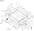
- the figures 2 to 6 illustrate in more detail an embodiment of the heat treatment module 4 according to the invention.
- the primary casing 5 is represented schematically in dotted lines and in transparency in order to make the secondary casing 6 visible and the direction of circulation of the various flows is schematically illustrated by arrows.
- the first direction corresponds to a direction of extension of at least part of a pipe of the module along an axis Ox of a reference mark Oxyz.
- the axis Ox is parallel to a flow axis of the flows, in particular of the gases, within the heat treatment module.
- the second direction is defined by an Oz axis of the coordinate system, orthogonal to the Ox axis.
- the third direction is defined by an axis Oy of the marker, perpendicular to the first and second directions and passing, in the examples illustrated, through each of the different compartments of the heat treatment module 4.
- the primary casing 5 comprises a plurality of primary walls 51 delimiting the primary volume 50 in which, on the one hand, the cooling fluid FR circulates and, on the other hand, the secondary casing 6 is arranged at least partially.
- the primary casing 5 has, in a non-limiting way, a substantially parallelepipedic and oblong structure. It comprises a first primary wall 511 and a second primary wall 512. These are interconnected by a first primary end wall 521 and a second primary end wall 522 which delimit the primary casing 5 along the first direction Ox.
- the primary casing 5 also comprises a first primary side wall 531 and a second primary side wall 532, delimiting the primary casing 5 along the third direction Oy.
- the primary casing 5 comprises a supply pipe 54 and an evacuation pipe 55 ensuring respectively the inlet and the outlet of the cooling fluid FR in the primary volume 50.
- said pipes 54, 55 are respectively carried by the first primary side wall 531 and the second primary side wall 532. It is nevertheless understood that such an arrangement is in no way limiting and that said pipes 54, 55 can be included in the same wall of the housing or in separate walls, whether adjacent or opposite.
- the secondary casing 6 comprises a plurality of secondary walls 64.
- the secondary casing 6 has a substantially parallelepipedic structure.
- the secondary box 6 also comprises a first secondary side wall 661 and a second secondary side wall 662, delimiting the secondary box 6 along the third direction Oy.
- All of these secondary walls 64 delimit a central part 67 of the secondary casing 6 in which essentially extend the first compartment 61, the second compartment 62 and the third compartment 63 as previously explained.
- said compartments are substantially oblong and extend parallel to the axis Ox, ie to the gas flow axis.
- the secondary casing 6 comprises a plurality of pipes emerging from the central part 67 of the secondary casing 6.
- the secondary box 6 comprises on the one hand a first supply line 681 and a first discharge line 682, fluidly connected to the first compartment 61, and on the other hand a second supply line 683 and a second discharge line. evacuation 684, fluidically connected to the second compartment 62 and to the third compartment 63.
- the first supply pipe 681 and the second supply pipe 683 on the one hand and the first evacuation pipe 682 and the second evacuation pipe 684 on the other hand emerge particularly from secondary walls 64 opposite each other within the housing.
- secondary 6 in this case, the first secondary end wall 651 and the second secondary end wall 652 respectively.
- the second supply line 683 can be connected to the second compartment 62 and to the third compartment 63 by a distribution portion 685, that is to say an enlargement allowing the distribution of the second flow F2 in the second compartment 62 and/ or in the third compartment 63.
- the second evacuation pipe 684 can be connected to the second compartment 62 and to the third compartment 63 by a manifold portion 686, that is to say a portion gradually reducing so as to collecting the second flow F2 leaving one and/or the other of said compartments.
- the supply pipes 681, 683 and/or the evacuation pipes 682, 684 are added and fixed mounted, for example by welding, on the central part 67 of the heat treatment module 4.
- At least the central part 67 of the secondary casing 6 forms a one-piece assembly.
- the first compartment 61, the second compartment 62 and the third compartment 63 are included in the same one-piece assembly, that is to say they cannot be separated from each other without resulting in the alteration or destruction of the secondary box 6.
- at least one of the various supply ducts 681, 683 and/or evacuation 682, 684 can form, with the central part 67 of the secondary housing 6, a one-piece assembly.
- the control device 41 is fixed permanently to such a one-piece assembly, the whole forming the heat treatment module 4.
- the primary walls 51 of the primary casing 5 and the secondary walls 65 of the secondary casing 6 extend at least in part at a non-zero distance from each other so as to delimit a space of circulation 40 of the cooling fluid FR within the primary volume 50 which surrounds all or part of the secondary casing 6.
- the primary housing 5 comprises a plurality of openings 56 intended for the passage of the various pipes 681-684 of the secondary housing 6.
- said openings 56 are equipped with a sealing member, not shown, such as a seal .
- said openings 56 are included in primary walls 51 separate from those carrying the pipes 54, 55.
- the openings 56 and the pipes 54, 55 are included in the same pair of primary walls 51 opposite one another.
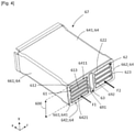
- the figure 3 , 4 and 5 further detail the internal arrangement of the heat treatment module 4.
- the picture 3 illustrates a sectional view taken along a 1000 plane while the figure 4 illustrates a section made along a 2000 plane, said planes being visible at the picture 2 .
- the third compartment 63 is particularly arranged in thermal contact with at least the first compartment 61. In this way, when the second flow F2 is sent into the third compartment 63, the heat treatment module 4 is configured to implement a heat exchange between the first flow F1, flowing in the first compartment 61, and the second flow F2, flowing in the third compartment 63.
- the third compartment 63 is, at least partially, placed between the first compartment 61 and the second compartment 62.
- the third compartment 63 is at least partially interposed between the first compartment 61 and the second compartment 62 along the third direction Oy.
- the heat treatment module is configured to implement a heat exchange between the first flow and the second flow.
- the second flow F2 is exclusively directed towards the second compartment 62, such an arrangement makes it possible to achieve at least partial thermal insulation of the first flow F1, flowing in the first compartment 61, with respect to the second flow F2.
- the third compartment 63 then forms an insulating layer interposed between the first compartment 61 and the second compartment 62.
- the secondary housing 6 comprises at least a first intermediate internal wall 691 delimiting at least in part on the one hand the first compartment 61 and on the other hand the third compartment 63. Otherwise formulated, the first intermediate internal wall 691 is common to the first compartment 61 and to the third compartment 63. In particular, the first intermediate internal wall 691 is configured to allow the thermal contact between the first compartment 61 and the third compartment 63. Thus, preferably, the third compartment 63 is attached to the first compartment by a wall, in particular the first intermediate internal wall 691, extending longitudinally along the axis Ox.
- the secondary casing 6 comprises a second intermediate internal wall 692 which delimits at least in part on the one hand the third compartment 63 and on the other hand the second compartment 62.
- the second internal wall intermediate 292 can be at least partly thermally insulating according to a particular embodiment.
- the first compartment 61 extends between the first secondary side wall 661 and the first intermediate internal wall 691
- the second compartment 62 extends between the second secondary side wall 662 and the second intermediate internal wall 692
- the third compartment 63 extends between the first intermediate internal wall 691 and the second intermediate internal wall 692.
- first intermediate internal wall 691 and the second intermediate internal wall 692 extend substantially parallel to each other, along the first direction Ox.
- the first intermediate internal wall 691 is connected in a sealed manner to an extreme face 680 of the first supply pipe 681 and/or of the second supply pipe 683.
- the second intermediate internal wall 692 extends opposite the distribution portion 685 and/or the collector portion 686.
- the third compartment 63 may comprise a first end 635 and/or a second end 636 open(s) so as to be fluidically connected to the second compartment 62 upstream and downstream in the direction of circulation of the second flow F2.
- control device 41 is then arranged in the secondary box 6 in order to direct the second flow F2 alternately in the second compartment 62 or in the third compartment 63.
- control device 41 is placed in the primary volume 50 so as to ensuring at least partial cooling, by means of the cooling fluid FR circulating in the primary casing 5, and preventing its degradation due to the high temperatures of the second flow F2.
- control device 41 can be placed at least partly in the second supply line 683, in particular in the distribution portion 685.
- the control device 41 can be at least partly placed in the central part 67 of the secondary casing 6, for example near the second intermediate internal wall 692 and the first end 635 of the third compartment 63.
- the control device 41 can be arranged in the second evacuation pipe 684, in particular in the manifold portion 686.
- the third compartment 63 is sized so as to extend over all or most of an internal height 600 of the secondary casing 6 comprised between a first internal face 6411 and a second internal face 6421 of the first secondary wall 641 and of the second secondary wall 642 respectively.
- the internal height 600 thus means the internal dimension of the secondary casing 6 measured along the second direction Oz.
- the third compartment 63 extends at least over an internal height specific to the first compartment 61.
- the third compartment 63 extends over at least most of an internal length 601 of the secondary housing 6.
- the internal length 601 of the secondary housing 6 is measured along the first direction Ox, between a first internal end face 6511 and a second internal end face 6521 of the first secondary end wall 651 and of the second secondary end wall 652 respectively.
- the third compartment 63 extends, along the first direction Ox, at least over the main part of the central part 67 of the secondary casing 6, that is to say over more than 50% of the internal length 601.
- the thermal contact between the first flow F1, circulating in the first compartment 61, and the second flow F2, when it circulates in the third compartment 63, is maximized and, on the other hand , the thermal insulation of the first flow F1, circulating in the first compartment 61, relative to the second flow F2 when the latter circulates in the second compartment 62, and vice versa, is optimized.
- first compartment 61, the second compartment 62 and the third compartment 63 are respectively characterized by a first width 611, a second width 621 and a third width 631.
- first width 611 the dimension measured between the first secondary side wall 661 and the first intermediate internal wall 691
- second width 621 the dimension measured between the second secondary side wall 662 and the second intermediate internal wall 692
- third width 631 the dimension between the first intermediate internal wall 691 and the second intermediate internal wall 692.
- the third compartment 63 is in particular configured so as to allow, depending on the mode of operation implemented, the thermal insulation of the first compartment 61 with respect to the second compartment 62, and vice versa.
- the third compartment 63 has a third width 631 greater than 30% of the first width 611 and/or the second width 621 without exceeding said first width 611 and/or second width 621.
- the first compartment 61 and/or the second compartment 62 comprise(s) (d) a plurality of passages 612, 622 intended for the circulation of the first flow F1 and of the second flow F2 respectively. It is understood that the number, dimensions or orientation of the passages 612, 622 illustrated are in no way limiting.
- the first compartment 61 and the second compartment 62 comprise a plurality of passages 612, 622 which extend longitudinally along the axis Ox.
- internal walls 613 connect the first secondary side wall 661 to the first intermediate internal wall 691 and delimit five passages 612 of the first flow F1. These extend along the third and first directions Oy, Ox for the heat exchange capable of being operated between the first compartment 61 and the third compartment 63.
- internal walls 623 connect the second secondary side wall 662 to the second intermediate internal wall 692 and delimit four passages 622 of the second flow F2.
- the passages 612, 622 are through. They extend over the entire internal length 601 of the central portion 67 of the secondary casing 6 and open into the supply lines 681, 683 and the evacuation lines 682, 684 of the secondary box 6.
- the figure 1 , 6 and 7 illustrate the path of the first flow F1 and second flow F2 in the internal combustion engine 1 and in the heat treatment module 4 according to the different operating modes.
- the first flow F1 is picked up from the outside.
- the first flow F1 is compressed in the compression device 21 and leaves it at high pressure and at a higher temperature. It is then sent to the heat treatment module 4 for its pre-cooling. It yields calories to the cooling fluid FR and emerges from the heat treatment module 4 at high pressure and at a lower temperature.
- the first flow F1 is then sent to the heat exchanger 24 in which colder water captures calories from the first flow F1 so as to lower its temperature further.
- the first flow F1 then enters through the intake face 111 into the cylinder head 11 and, after combustion, burnt gases are evacuated through the exhaust face 112 of the cylinder head 11.
- the burnt gases can be sent to the turbine 22 of the compression device 21 in order to drive it, as well as a compression wheel of the compression device 21, in rotation.
- the burnt gases can be taken from the exhaust manifold 13 and sent to the recirculation circuit 3 in which they constitute the second flow F2.
- This second stream F2 high pressure and at very high temperature, is sent to the heat treatment module 4 in order to be cooled before being returned to the intake circuit 2 to be mixed with the first stream F1.
- the second flow F2 can be admitted within the circuit intake 2 at the level of the intake ducts and/or at the level of the intake distributor 12, that is to say downstream of the heat exchanger 24.
- the second flow F2 can be admitted into the intake circuit at a pipe of the intake circuit 2 between the heat treatment module 4 and the heat exchanger 24, as shown.
- the figure 6 and 7 illustrate the different heat exchanges implemented in the heat treatment module 4 according to different engine operating modes.
- the circulation of the cooling fluid FR is interrupted, in particular at the level of the thermal module 4, so as to ensure the cooling neither of the first flow F1 nor of the second flow F2 within said heat treatment module 4.
- the control device 41 is moved in order to direct the second flow F2 towards the third compartment 63 so that the second flow F2, hotter than the first flow F1 circulating in the first compartment 61, transfers calories to the latter.
- the exchange capacities of the first and second heat exchangers are limited. Only the third heat exchanger is configured to implement an effective heat exchange between the first flow F1 and the second flow F2.
- the first flow F1 thus leaves the heat treatment module 4 at a higher temperature and is sent directly to the intake face 111.
- the second flow F2 is sent to the intake circuit 2, and, similar to the first flow, bypasses the heat exchanger 24 to be sent directly to the intake face 111.
- the figure 7 illustrates a second mode of operation of the internal combustion engine 1.
- the internal combustion engine 1 is hot and it is necessary to cool the first flow F1 and the second flow F2 upstream of the intake face 111.
- Such a mode of operation is in particular implemented during the driving phases of the vehicle 100 as previously described.
- the cooling fluid FR circulates in the primary housing 5.
- the first flow F1 circulates in the first compartment 61 while the control device 41 is moved in order to send the second flow F2 to the second compartment 62.
- the first stream F1 which is hotter, transfers calories to the cooling fluid FR and emerges cooled from the heat treatment module 4.
- the first stream F1 is then directed to the heat exchanger 24 by the cooling device. valve 14.
- the first flow F1 transfers calories to the colder glycol water, then is returned to the inlet face 111.
- the second flow F2 transfers calories to the cooling fluid FR and comes out cooled from the heat treatment module 4.
- the second flow F2 then joins the first flow in the intake circuit 2 at one previously exposed alternatives then is sent to the intake face 111 of the cylinder head 11.
- the third compartment 63 thus interposed, in particular along the third direction Oy, between the first compartment 61 and the second compartment 62 constitutes an at least partially thermally insulating layer.
- the third compartment 63 ensures, at least in part, the thermal insulation of the first compartment 61 with respect to the second compartment 62, and vice versa. In this way, any heat exchange between the first flow F1 and the second flow F2, which is hotter, is limited, or even zero.
- the heat treatment module 4 advantageously limits the thermal contact surface between the second flow F2 circulating in the second compartment 62, that is to say the EGR flow, and the cooling fluid FR, preventing thus the production possible clogging conventionally observed when an EGR flow undergoes excessive cooling.
- the limitation of the thermal contact surface results from the adjoining of the third compartment 63 and the second compartment 62 which share at least one common wall, here the second intermediate internal wall 692.
- the present invention thus proposes a heat treatment module for an internal combustion engine comprising a primary casing in which a cooling fluid circulates and in which extends at least in part a secondary casing including a first compartment intended to implement an exchange between a first flow, in particular an intake gas flow, and said cooling fluid, a second compartment intended to implement a heat exchange between a second flow, in particular an EGR gas flow, and said cooling fluid, and a third compartment intended for the circulation of the second flow and capable of ensuring thermal insulation of the first compartment vis-à-vis the second compartment on reaching a predetermined temperature threshold, in particular on reaching a predetermined temperature threshold of the combustion engine internal.
- the invention also relates to an internal combustion engine comprising said heat treatment module.
- the present invention cannot however be limited to the means and configurations described and illustrated here and it also extends to any equivalent means or configuration and to any technically effective combination of such means.
- the shape and dimensions of the compartments, as well as the number of passages can be modified without harming the invention insofar as they ultimately fulfill the functions described and illustrated in this document.
Landscapes
- Engineering & Computer Science (AREA)
- Mechanical Engineering (AREA)
- General Engineering & Computer Science (AREA)
- Physics & Mathematics (AREA)
- Thermal Sciences (AREA)
- Chemical & Material Sciences (AREA)
- Combustion & Propulsion (AREA)
- Exhaust-Gas Circulating Devices (AREA)
- Exhaust Gas After Treatment (AREA)
Abstract
Description
- La présente invention concerne module de traitement thermique pour un moteur à combustion interne de véhicule, notamment de véhicule automobile, ainsi que ledit moteur à combustion interne. Egalement, la présente invention concerne un procédé de fonctionnement dudit moteur à combustion interne et un véhicule comprenant le module de traitement thermique et/ou le moteur à combustion interne.
- Afin de réduire des rejets de polluants générés par les moteurs thermiques, ou moteurs à combustion interne, lors de la combustion, ceux-ci comprennent classiquement un circuit de recirculation configuré pour ramener des gaz brûlés de l'échappement, c'est-à-dire en aval de la combustion dans des cylindres du moteur thermique, vers des conduits d'admission du moteur. Lesdits gaz sont qualifiés de gaz recirculés ou gaz EGR, de l'acronyme anglais « Exhaust Gaz Recirculation », et peuvent, par exemple, consister en des gaz recirculés haute pression ou basse pression.
- Selon les phases de fonctionnement du moteur, les gaz recirculés peuvent passer ou non par un module de traitement thermique, notamment de refroidissement, disposé en amont de l'admission et dans lequel circule un fluide de refroidissement. De manière connue, un volet de dérivation, ou « by-pass » en anglais, est agencé dans le circuit de recirculation en amont du module de traitement thermique afin de diriger les gaz recirculés vers une conduite de dérivation et contourner sélectivement ledit module de traitement thermique, par exemple lors de phases de fonctionnement à froid du moteur à combustion interne.
- Un tel arrangement s'accompagne d'une augmentation conséquente de l'encombrement du groupe motopropulseur qui comprend le moteur à combustion interne et les divers accessoires nécessaires à son fonctionnement, le rendant peu compatible avec les contraintes, notamment esthétiques, imposées par les constructeurs.
- Additionnellement, il a été constaté que la mise en œuvre d'un échange thermique entre le flux de gaz recirculés et un fluide de refroidissement présentant une température trop basse résulte en la génération d'encrassements colmatant susceptibles d'entraver le bon fonctionnement du module de traitement thermique.
- L'invention s'inscrit dans ce contexte et vise à résoudre ces différents problèmes. A cette fin, l'invention porte sur un module de traitement thermique pour moteur à combustion interne, le module de traitement thermique comprenant un boîtier primaire délimitant un volume primaire, destiné à la circulation d'un fluide de refroidissement, et un boîtier secondaire s'étendant au moins en partie dans le volume primaire et incluant une pluralité de compartiments, le module de traitement thermique étant caractérisé en ce que:
- le boîtier secondaire comprend un premier compartiment destiné à mettre en œuvre un échange thermique entre un premier flux, notamment un flux de gaz d'admission, et le fluide de refroidissement ;
- le boîtier secondaire comprend un deuxième compartiment destiné à mettre en œuvre un échange thermique entre un deuxième flux, notamment un flux de gaz EGR, et le fluide de refroidissement ;
- le boîtier secondaire comprend un troisième compartiment destiné à la circulation du deuxième flux et apte à assurer une isolation thermique du premier compartiment vis-à-vis du deuxième compartiment à l'atteinte d'un seuil de température prédéterminé, notamment à l'atteinte d'un seuil de température prédéterminé du moteur à combustion interne ;
- le module de traitement thermique comprend un dispositif de contrôle de la circulation du deuxième flux configuré pour diriger sélectivement le deuxième flux dans le troisième compartiment ou dans le deuxième compartiment.
- Le troisième compartiment peut être disposé au contact thermique d'au moins le premier compartiment. Particulièrement, le troisième compartiment peut être interposé entre le premier compartiment et le deuxième compartiment.
- Selon une caractéristique optionnelle, le troisième compartiment peut comprendre une première extrémité et/ou une deuxième extrémité ouverte(s), le troisième compartiment étant fluidiquement relié au deuxième compartiment en amont et en aval selon un sens de circulation du deuxième flux.
- Selon une caractéristique optionnelle, le boîtier secondaire peut comprendre d'une part une première conduite d'alimentation et une première conduite d'évacuation, fluidiquement reliées au premier compartiment, et d'autre part une deuxième conduite d'alimentation et une deuxième conduite d'évacuation, fluidiquement reliées au deuxième compartiment et au troisième compartiment.
- Particulièrement, la deuxième conduite d'alimentation peut être reliée au deuxième compartiment et au troisième compartiment par une portion de répartition et/ou la deuxième conduite d'évacuation peut être reliée au deuxième compartiment et au troisième compartiment par une portion de collecteur.
- Optionnellement, le boîtier secondaire peut comprendre au moins une première paroi interne intermédiaire délimitant au moins en partie d'une part le premier compartiment et d'autre part le troisième compartiment.
- Selon une caractéristique optionnelle, le boîtier secondaire peut comprendre au moins une première paroi secondaire et une deuxième paroi secondaire, le troisième compartiment s'étendant sur tout ou l'essentiel d'une hauteur interne du boîtier secondaire comprise entre une première face interne et une deuxième face interne de la première paroi secondaire et de la deuxième paroi secondaire respectivement.
- Selon une caractéristique optionnelle, le boîtier secondaire peut comprendre au moins une première paroi extrêmale secondaire et une deuxième paroi extrémale secondaire, le troisième compartiment s'étendant sur au moins l'essentiel d'une longueur interne du boîtier secondaire comprise entre une première face extrême interne et une deuxième face extrême interne de la première paroi extrêmale secondaire et de la deuxième paroi extrêmale secondaire respectivement.
- Selon une caractéristique optionnelle, le premier compartiment, le deuxième compartiment et le troisième compartiment peuvent respectivement être caractérisés par une première largeur, une deuxième largeur et une troisième largeur, mesurées le long d'une direction Oy, la troisième largeur étant supérieure à 30% de la première largeur et/ou de la deuxième largeur sans excéder ladite/lesdites première largeur et/ou deuxième largeur.
- Selon une caractéristique optionnelle, le premier compartiment et/ou le deuxième compartiment peu(ven)t comprendre une pluralité de passages destinés à la circulation du premier flux et du deuxième flux respectivement.
- Le dispositif de contrôle peut être disposé dans le volume primaire, notamment dans le boîtier secondaire disposé dans le volume primaire. Notamment, le dispositif de contrôle peut comprendre un volet monté pivotant.
- L'invention concerne également un moteur à combustion interne comprenant un module de traitement thermique tel que précédemment exposé.
- L'invention concerne, en outre, un véhicule automobile comprenant un module de traitement thermique et/ou un moteur à combustion interne tel qu'exposé précédemment.
- L'invention concerne enfin un procédé de fonctionnement d'un moteur à combustion interne comprenant un module de traitement thermique selon l'invention, le procédé comprenant au moins :
- une première étape de fonctionnement du moteur à combustion interne dans laquelle le dispositif de contrôle est configuré pour diriger le deuxième flux vers le troisième compartiment, et
- une deuxième étape de fonctionnement du moteur à combustion interne dans laquelle le dispositif de contrôle est configuré pour diriger le deuxième flux vers le deuxième compartiment à l'atteinte d'un seuil de température prédéterminé, notamment à l'atteinte d'un seuil de température prédéterminé du moteur à combustion interne.
- D'autres détails, caractéristiques et avantages ressortiront plus clairement à la lecture de la description détaillée donnée ci-après, à titre indicatif et non limitatif, en relation avec les différents exemples de réalisation illustrés sur les figures suivantes :
- [
Fig. 1 ] Lafigure 1 est une représentation schématique d'une partie d'un mode de réalisation d'un moteur à combustion selon l'invention. - [
Fig. 2 ] Lafigure 2 représente une vue en perspective schématique d'un mode de réalisation d'un module de traitement thermique du moteur à combustion interne. - [
Fig. 3 ] Lafigure 3 est une vue de dessus en coupe longitudinale du module de traitement thermique. - [
Fig. 4 ] Lafigure 4 est une vue en perspective d'une partie centrale du module de traitement thermique. - [
Fig. 5 ] La figure est une vue de face de la partie centrale illustrée à lafigure 4 . - [
Fig. 6 ] Lafigure 6 est une représentation schématique du module de traitement thermique lorsque le moteur à combustion interne met en œuvre un premier mode de fonctionnement. - [
Fig. 7 ] Lafigure 7 est une représentation schématique du module de traitement thermique lorsque le moteur à combustion interne met en œuvre un deuxième mode de fonctionnement. - La
figure 1 est une représentation schématique d'une partie d'un véhicule 100, notamment d'un véhicule 100 automobile, comprenant un moteur 1 à combustion interne selon un mode de réalisation destiné à un véhicule 100, en particulier un véhicule 100 automobile. - Le moteur 1 à combustion interne comprend un carter-cylindres (non représenté) et une culasse 11 fixée à celui-ci. La culasse 11 comprend une face d'admission 111, par laquelle entre un premier flux F1, et une face d'échappement 112, par exemple opposée à la face d'admission 111, de laquelle sont évacués, après combustion, des gaz brûlés.
- Notamment, le premier flux F1 consiste en un flux de gaz d'admission, ou flux d'air d'admission. Ledit air peut être capté depuis l'extérieur du véhicule 100, en général au niveau de la face avant du véhicule 100. De manière alternative, un tel flux d'air peut être issu d'un pavillon du véhicule 100, d'une aile arrière ou, plus généralement, de toutes zones du véhicule 100 susceptibles d'être balayées par un flux d'air extérieur. Il est entendu que les termes « premier flux F1 », « flux de gaz d'admission », ou « flux d'air d'admission » seront utilisés sans distinction dans l'ensemble de la description ci-après.
- Le moteur 1 à combustion interne comprend un circuit d'admission 2 relié à la face d'admission 111 de la culasse 11 et configuré pour assurer la circulation d'au moins le premier flux F1. Particulièrement, le circuit d'admission 2 peut être relié à un ou plusieurs conduits d'admission et/ou, tel qu'illustré, à un répartiteur d'admission 12 fixé à la culasse 11.
- Le circuit d'admission 2 comprend un dispositif de compression 21 destiné à comprimer le premier flux préalablement à son entrée par la face d'admission 111. En l'espèce, le dispositif de compression 21 consiste en un turbocompresseur comprenant une turbine 22 dont un axe de rotation est confondu avec un axe de rotation d'un compresseur 23 d'air d'admission. De manière alternative, le dispositif de compression 21 peut consister en un compresseur électrique.
- Le circuit d'admission 2 comprend également un échangeur de chaleur 24 configuré pour mettre en œuvre un échange thermique entre le premier flux F1 et un circuit d'eau, par exemple de l'eau glycolée, non représenté. L'échangeur de chaleur 24 est disposé en amont de la face d'admission 111 selon le sens de circulation du premier flux F1. Particulièrement, l'échangeur de chaleur 24, est disposé entre le dispositif de compression 21 et la face d'admission 111 de sorte à permettre le traitement thermique, notamment le refroidissement, du premier flux F1 comprimé. De manière préférentielle, l'échangeur de chaleur 24 est agencé dans le circuit d'admission 2 entre le dispositif de compression 21 et le répartiteur d'admission 12.
- De manière alternative, non illustrée, l'échangeur de chaleur 24 peut comprendre le répartiteur d'admission 12. L'échangeur de chaleur 24 peut alors être fixé sur la face d'admission 111 et connecté avec des conduits d'admission creusés dans la culasse 11 et menant à une pluralité de chambres de combustion.
- Pour répondre aux normes actuelles de dépollution, les gaz brulés sortant par la face d'échappement 112 peuvent être réinjectés à l'admission. A cette fin, le moteur 1 à combustion interne selon l'invention comprend un circuit de recirculation 3 relié à la face d'échappement 112 de la culasse 11 et configuré pour assurer la circulation d'un deuxième flux F2. Notamment, le deuxième flux F2 consiste en lesdits gaz brûlés, également indistinctement qualifiés de gaz recirculés ou de gaz EGR, tiré de l'anglais « Exhaust Gas Recirculation ». Il est entendu que, dans l'ensemble de la description ci-après, les termes « amont » et « aval » se réfèrent au sens d'écoulement des premier flux F1 et deuxième flux F2 dans le moteur 1 à combustion interne.
- De manière particulière, les gaz recirculés formant le deuxième flux peuvent consister en des gaz haute pression et haute température prélevés directement depuis un collecteur d'échappement 13 disposé au niveau de la face d'échappement 112 de la culasse 11.
- Lors du fonctionnement du moteur 1 à combustion interne les gaz recirculés circulent à hautes températures, par exemple de l'ordre de 700°C. Il peut donc être nécessaire d'assurer leur refroidissement préalablement à leur réadmission dans les conduits d'admission d'air. Notamment, le moteur 1 à combustion interne est configuré pour mettre en œuvre une pluralité de modes de fonctionnement distincts, lesdits modes de fonctionnement pouvant s'accompagner d'un refroidissement à des degrés variables du deuxième flux F2.
- Similairement, il peut être nécessaire d'assurer le refroidissement du premier flux F1, c'est-à-dire des gaz d'admission, préalablement à son arrivée dans les conduits d'admission. Néanmoins, l'échangeur de chaleur 24 tel que précédemment décrit peut ne pas être suffisant et/ou son fonctionnement peut s'accompagner d'importantes pertes énergétiques. Aussi, il est classiquement connu d'intégrer un système de pré-refroidissement du premier flux F1, disposé en amont de l'échangeur de chaleur 24.
- Afin d'au moins assurer d'une part le pré-refroidissement du premier flux F1 et d'autre part le refroidissement du deuxième flux F2, le moteur 1 à combustion interne comprend un module de traitement thermique 4 selon l'invention.
- Le module de traitement thermique 4 comprend un boîtier primaire 5 délimitant un volume primaire 50, destiné à la circulation d'un fluide de refroidissement FR tel que de l'eau glycolée.
- Le module de traitement thermique 4 comprend également un boîtier secondaire 6 s'étendant au moins en partie dans le volume primaire 50 et comprenant une pluralité de compartiments, notamment au moins un premier compartiment 61, un deuxième compartiment 62 et un troisième compartiment 63. En d'autres termes, le boîtier secondaire 6 et les différents compartiments 61, 62, 63 qu'il comprend sont au moins en partie logés dans le boîtier primaire 5 de sorte à baigner dans le fluide de refroidissement FR. Notamment, lesdits compartiments peuvent être distincts et hermétiques les uns des autres au sein du boîtier secondaire 6. Particulièrement, au moins le premier compartiment 61 peut être distinct et hermétique du deuxième compartiment 62 et du troisième compartiment 63 au sein du boîtier secondaire 6.
- Le premier compartiment 61 est destiné à mettre en œuvre un échange thermique entre le premier flux F1 le fluide de refroidissement FR. Autrement dit, le premier compartiment est destiné à la circulation et au traitement thermique, notamment au pré-refroidissement, du premier flux F1.
- Le deuxième compartiment 62 est, quant à lui, destiné à mettre en œuvre un échange thermique entre le deuxième flux F2 et le fluide de refroidissement. Le deuxième compartiment 62 est ainsi destiné à la circulation et au traitement thermique du deuxième flux F2.
- Enfin, le troisième compartiment 63 est destiné à la circulation du deuxième flux F2 et est apte à assurer une isolation thermique du premier compartiment 61 vis-à-vis du deuxième compartiment 62 à l'atteinte d'un seuil de température prédéterminé, notamment à l'atteinte d'un seuil de température prédéterminé du moteur 1 à combustion interne. A titre d'exemple non limitatif, une telle température peut être une température du fluide de refroidissement du moteur à combustion interne.
- En d'autres termes, tel que davantage exposé ci-après, un tel troisième compartiment 63 est apte à limiter, voire prévenir, un échange thermique entre le premier flux F1, circulant dans le premier compartiment 61, et le deuxième flux F2, circulant alors dans le deuxième compartiment 62.
- Notamment, le module de traitement thermique 4 selon l'invention est configuré de sorte à mettre en œuvre une telle circulation du deuxième flux F2 ou une telle isolation de manière consécutive, c'est-à-dire que de telles fonctions ne sont pas exécutées concomitamment par ledit module.
- Lorsque le module de traitement thermique 4 est installé dans le moteur 1 à combustion interne, le premier compartiment 61 est compris dans le circuit d'admission 2 et disposé entre le dispositif de compression 21 et la face d'admission 111. Plus particulièrement, le premier compartiment 61 est disposé entre le dispositif de compression 21 et l'échangeur de chaleur 24. Le deuxième compartiment 62 et le troisième compartiment 63 du module de traitement thermique 4 sont compris dans le circuit de recirculation 3.
- Avantageusement, le module de traitement thermique 4 comprend un dispositif de contrôle 41, notamment mobile, de la circulation du deuxième flux F2 configuré pour diriger sélectivement le deuxième flux F2 dans le troisième compartiment 63 ou dans le deuxième compartiment 62 selon le mode de fonctionnement mis en œuvre par le moteur 1 à combustion interne.
- Avantageusement et afin de limiter l'encombrement généré par le module de traitement thermique 4, le dispositif de contrôle 41 est disposé dans le volume primaire 50. De manière particulière, le dispositif de contrôle 41 est logé dans le boîtier secondaire 6 lui-même au moins en partie disposé dans le volume primaire 50.
- A titre d'exemple, le dispositif de contrôle 41 peut comprendre un volet monté pivotant. Ledit volet est apte à obturer ou ouvrir un passage du deuxième flux F2 de gaz dans le deuxième compartiment et, de façon simultanée et inverse, à ouvrir ou obturer un passage du deuxième flux F2 de gaz dans le troisième compartiment.
- Additionnellement, le moteur 1 à combustion interne comprend un ensemble de contrôle, non représenté, configuré pour diriger les déplacements du dispositif de contrôle 41 selon le mode de fonctionnement mis en œuvre par le moteur 1 à combustion interne. Un tel ensemble de contrôle peut, par exemple, comprendre un capteur tel qu'un capteur de température et/ou de pression, et un calculateur 101.
- Ainsi, le moteur 1 à combustion interne selon l'invention est configuré pour mettre en œuvre une pluralité de modes de fonctionnements et comprend au moins le circuit d'admission 2 configuré pour assurer la circulation d'au moins le premier flux F1, le circuit de recirculation 3 configuré pour assurer la circulation du deuxième flux, et le module d'échange thermique 4 :
- le premier compartiment 61 étant compris dans le circuit d'admission 2,
- le deuxième compartiment 62 et le troisième compartiment 63 étant compris dans le circuit de recirculation,
- le dispositif de contrôle 41 de la circulation du deuxième flux dirigeant sélectivement le deuxième flux F2 vers le troisième compartiment 63 ou vers le deuxième compartiment 62 selon le mode de fonctionnement mis en œuvre par le moteur 1 à combustion interne.
- De la sorte, le module de traitement thermique 4 est assimilable à une combinaison d'une pluralité d'échangeurs thermiques fonctionnant sélectivement selon le mode de fonctionnement mis en œuvre par le moteur à combustion interne 1. Notamment, il peut être modélisé comme une combinaison:
- d'un premier échangeur thermique, configuré entre le premier compartiment et le fluide de refroidissement FR pour mettre en œuvre un échange thermique entre le premier flux F1 et le fluide de refroidissement FR,
- d'un deuxième échangeur thermique, configuré entre le deuxième compartiment et le fluide de refroidissement FR pour mettre en œuvre un échange thermique entre le deuxième flux F2 et le fluide de refroidissement, et
- d'un troisième échangeur thermique, configuré pour mettre en œuvre un échange thermique entre le premier compartiment et le troisième compartiment.
- Il est à noter que, de préférence, le coefficient d'échange thermique entre le troisième compartiment et le fluide de refroidissement FR est inférieur au coefficient d'échange thermique entre le deuxième compartiment 62 et le fluide de refroidissement FR.
- Les
figures 2 à 6 illustrent plus en détails un mode de réalisation du module de traitement thermique 4 selon l'invention. Dans ces figures, le boîtier primaire 5 est représenté schématiquement en lignes pointillées et en transparence afin de rendre visible le boîtier secondaire 6 et le sens de circulation des différents flux est illustré schématiquement par des flèches. - L'ensemble des figures et de la description ci-après se réfèrent à une orientation du module de traitement thermique 4 définie selon une première direction, une deuxième direction et une troisième direction. La première direction correspond à une direction d'extension d'au moins une partie d'une conduite du module le long d'un axe Ox d'un repère Oxyz. Particulièrement, l'axe Ox est parallèle à un axe d'écoulement des flux notamment des gaz, au sein du module de traitement thermique. La deuxième direction est définie par un axe Oz du repère, orthogonal à l'axe Ox. La troisième direction est définie par un axe Oy du repère, perpendiculaire aux première et deuxième directions et passant, dans les exemples illustrés, par chacun des différents compartiments du module de traitement thermique 4.
- Egalement, il est entendu que les termes « primaire », « secondaire », « premier », « deuxième » visent à distinguer les différents composants de l'invention et n'ont en rien vocation à déterminer une hiérarchie desdits composants.
- Le boîtier primaire 5 comprend une pluralité de paroi primaires 51 délimitant le volume primaire 50 dans lequel, d'une part, circule le fluide de refroidissement FR et, d'autre part, est disposé au moins partiellement le boîtier secondaire 6.
- Particulièrement, dans l'exemple illustré le boîtier primaire 5 présente, de manière non limitative, une structure sensiblement parallélépipédique et oblongue. Il comprend une première paroi primaire 511 et une deuxième paroi primaire 512. Celles-ci sont reliées entre elles par une première paroi extrémale primaire 521 et une deuxième paroi extrémale primaire 522 qui délimitent le boîtier primaire 5 le long de la première direction Ox. Le boîtier primaire 5 comprend également une première paroi latérale primaire 531 et une deuxième paroi latérale primaire 532, délimitant le boîtier primaire 5 le long de la troisième direction Oy.
- Le boîtier primaire 5 comprend une tubulure d'alimentation 54 et une tubulure d'évacuation 55 assurant respectivement l'entrée et la sortie du fluide de refroidissement FR dans le volume primaire 50. Dans le mode de réalisation représenté, lesdites tubulures 54, 55 sont respectivement portées par la première paroi latérale primaire 531 et la deuxième paroi latérale primaire 532. Il est néanmoins entendu qu'un tel agencement n'est en rien limitatif et que lesdites tubulures 54, 55 peuvent être comprises dans une même paroi du boîtier ou dans des parois distinctes, que celles-ci soient adjacentes ou opposées.
- Similairement, le boîtier secondaire 6 comprend une pluralité de parois secondaires 64. Particulièrement, selon l'exemple non limitatif illustré, le boîtier secondaire 6 présente une structure sensiblement parallélépipédique.
- Il comprend une première paroi secondaire 641 et une deuxième paroi secondaire 642, lesquelles sont reliées entre elles par une première paroi extrêmale secondaire 651 et une deuxième paroi extrêmale secondaire 652 qui délimitent le boîtier secondaire 6 le long de la première direction Ox. Le boîtier secondaire 6 comprend également une première paroi latérale secondaire 661 et une deuxième paroi latérale secondaire 662, délimitant le boîtier secondaire 6 le long de la troisième direction Oy.
- L'ensemble de ces parois secondaires 64 délimite une partie centrale 67 du boîtier secondaire 6 dans lequel s'étendent essentiellement le premier compartiment 61, le deuxième compartiment 62 et le troisième compartiment 63 tels que précédemment exposés. Notamment, lesdits compartiments sont sensiblement oblongs et s'étendent parallèlement à l'axe Ox, c'est-à-dire à l'axe d'écoulement des gaz.
- Afin de raccorder fluidiquement le module de traitement thermique 4 au circuit d'admission 2 et au circuit de recirculation 3, le boîtier secondaire 6 comprend une pluralité de conduites émergeant de la partie centrale 67 du boîtier secondaire 6.
- Le boîtier secondaire 6 comprend d'une part une première conduite d'alimentation 681 et une première conduite d'évacuation 682, fluidiquement reliées au premier compartiment 61, et d'autre part une deuxième conduite d'alimentation 683 et une deuxième conduite d'évacuation 684, fluidiquement reliées au deuxième compartiment 62 et au troisième compartiment 63.
- La première conduite d'alimentation 681 et la deuxième conduite d'alimentation 683 d'une part et la première conduite d'évacuation 682 et la deuxième conduite d'évacuation 684 d'autre part émergent particulièrement de parois secondaires 64 opposées au sein du boîtier secondaire 6, en l'espèce, de la première paroi extrêmale secondaire 651 et de la deuxième paroi extrêmale secondaire 652 respectivement.
- Particulièrement, et tel que visible aux
figures 2 ou3 , la deuxième conduite d'alimentation 683 peut être reliée au deuxième compartiment 62 et au troisième compartiment 63 par une portion de répartition 685, c'est-à-dire un élargissement permettant la répartition du deuxième flux F2 dans le deuxième compartiment 62 et/ou dans le troisième compartiment 63. Similairement, la deuxième conduite d'évacuation 684 peut être reliée au deuxième compartiment 62 et au troisième compartiment 63 par une portion de collecteur 686, c'est-à-dire une portion se réduisant progressivement de sorte à collecter le deuxième flux F2 sortant de l'un et/ou de l'autre desdits compartiments. - Tel qu'illustré, les conduites d'alimentation 681, 683 et/ou les conduites d'évacuation 682, 684 sont rapportées et montées fixes, par exemple par soudage, sur la partie centrale 67 du module de traitement thermique 4.
- De manière particulière, au moins la partie centrale 67 du boîtier secondaire 6 forme un ensemble monobloc. En d'autres termes, le premier compartiment 61, le deuxième compartiment 62 et le troisième compartiment 63 sont compris dans un même ensemble monobloc, c'est-à-dire qu'ils ne peuvent être séparés les uns des autres sans résulter en l'altération ou en la destruction du boîtier secondaire 6. De manière optionnelle au moins l'une des différentes conduites d'alimentation 681, 683 et/ou d'évacuation 682, 684 peut former, avec la partie centrale 67 du boîtier secondaire 6, un ensemble monobloc. De préférence encore, le dispositif de contrôle 41 est fixé à demeure à un tel ensemble monobloc, le tout formant le module de traitement thermique 4.
- Ainsi, au sein du module de traitement thermique 4, les parois primaires 51 du boîtier primaire 5 et les parois secondaires 65 du boîtier secondaire 6 s'étendent au moins en partie à distance non nulle les unes des autres de sorte à délimiter un espace de circulation 40 du fluide de refroidissement FR au sein du volume primaire 50 qui entoure tout ou partie du boîtier secondaire 6.
- Egalement, le boîtier primaire 5 comprend une pluralité d'ouvertures 56 destinés au passage des différentes conduites 681-684 du boîtier secondaire 6. Avantageusement, lesdites ouvertures 56 sont équipées d'un organe d'étanchéité, non représenté, tel qu'un joint. De manière préférentielle, lesdites ouvertures 56 sont comprises dans des parois primaires 51 distinctes de celles portant les tubulures 54, 55.
- Selon une alternative non illustrée visant à réduire l'encombrement généré par le module de traitement thermique 4, les ouvertures 56 et les tubulures 54, 55 sont comprises dans une même paire de parois primaires 51 opposées l'une à l'autre.
- Les
figures 3 ,4 et5 détaillent davantage l'arrangement interne du module de traitement thermique 4. Lafigure 3 illustre une vue en coupe réalisée le long d'un plan 1000 tandis que lafigure 4 illustre une coupe réalisée le long d'un plan 2000, lesdits plans étant visibles à lafigure 2 . - Au sein du module de traitement thermique 4, le troisième compartiment 63 est particulièrement disposé au contact thermique d'au moins le premier compartiment 61. De la sorte, lorsque le deuxième flux F2 est envoyé dans le troisième compartiment 63, le module de traitement thermique 4 est configuré pour mettre en œuvre un échange thermique entre le premier flux F1, circulant dans le premier compartiment 61, et le deuxième flux F2, circulant dans le troisième compartiment 63.
- Selon l'exemple particulier de réalisation illustré, le troisième compartiment 63 est, au moins en partie, disposé entre le premier compartiment 61 et le deuxième compartiment 62. En d'autres termes, le troisième compartiment 63 est au moins partiellement interposé entre le premier compartiment 61 et le deuxième compartiment 62 le long de la troisième direction Oy.
- Un tel arrangement s'accompagne de différents avantages selon le mode de fonctionnement mis en œuvre par le moteur 1 à combustion interne. Lorsque le deuxième flux F2 est dirigé vers le troisième compartiment 63 tel que précédemment exposé, le module de traitement thermique est configuré pour mettre en œuvre un échange thermique entre le premier flux et le deuxième flux. En revanche, lorsque le deuxième flux F2 est exclusivement dirigé vers le deuxième compartiment 62, un tel arrangement permet de réaliser une isolation thermique au moins partielle du premier flux F1, circulant dans le premier compartiment 61, par rapport au deuxième flux F2. Le troisième compartiment 63 forme alors une couche isolante interposée entre le premier compartiment 61 et le deuxième compartiment 62. Ces différents modes de fonctionnement seront davantage détaillés ci-après.
- Le boîtier secondaire 6 comprend au moins une première paroi interne intermédiaire 691 délimitant au moins en partie d'une part le premier compartiment 61 et d'autre part le troisième compartiment 63. Autrement formulé, la première paroi interne intermédiaire 691 est commune au premier compartiment 61 et au troisième compartiment 63. Notamment, la première paroi interne intermédiaire 691 est configurée pour permettre le contact thermique entre le premier compartiment 61 et le troisième compartiment 63. Ainsi de manière préférentielle, le troisième compartiment 63 est accolé au premier compartiment par une paroi, notamment la première paroi interne intermédiaire 691, s'étendant longitudinalement selon l'axe Ox.
- Egalement, dans le mode de réalisation illustré, le boîtier secondaire 6 comprend une deuxième paroi interne intermédiaire 692 qui délimite au moins en partie d'une part le troisième compartiment 63 et d'autre part le deuxième compartiment 62. Notamment, la deuxième paroi interne intermédiaire 292 peut être au moins en partie thermiquement isolante selon un mode de réalisation particulier.
- Ainsi, dans l'exemple illustré, le premier compartiment 61 s'étend entre la première paroi latérale secondaire 661 et la première paroi interne intermédiaire 691, le deuxième compartiment 62 s'étend entre la deuxième paroi latérale secondaire 662 et la deuxième paroi interne intermédiaire 692 et le troisième compartiment 63 s'étend entre la première paroi interne intermédiaire 691 et la deuxième paroi interne intermédiaire 692.
- En l'espèce, la première paroi interne intermédiaire 691 et la deuxième paroi interne intermédiaire 692 s'étendent sensiblement parallèlement l'une à l'autre, le long de la première direction Ox. La première paroi interne intermédiaire 691 est connectée de manière étanche à un pan extrême 680 de la première conduite d'alimentation 681 et/ou de la deuxième conduite d'alimentation 683. A l'inverse, la deuxième paroi interne intermédiaire 692 s'étend en regard de la portion de répartition 685 et/ou de la portion de collecteur 686.
- De manière particulière, le troisième compartiment 63 peut comprendre une première extrémité 635 et/ou une deuxième extrémité 636 ouverte(s) de sorte à être fluidiquement relié au deuxième compartiment 62 en amont et en aval selon le sens de circulation du deuxième flux F2.
- Le dispositif de contrôle 41 est alors arrangé dans le boîtier secondaire 6 afin de diriger le deuxième flux F2 alternativement dans le deuxième compartiment 62 ou dans le troisième compartiment 63. Avantageusement, le dispositif de contrôle 41 est disposé dans le volume primaire 50 de sorte à en assurer le refroidissement au moins partiel, par l'intermédiaire du fluide de refroidissement FR circulant dans le boîtier primaire 5, et à prévenir sa dégradation du fait des températures élevées du deuxième flux F2.
- A titre d'exemple, le dispositif de contrôle 41 peut être disposé au moins en partie dans la deuxième conduite d'alimentation 683, notamment dans la portion de répartition 685. De manière alternative, le dispositif de contrôle 41 peut être au moins partiellement disposé dans la partie centrale 67 du boîtier secondaire 6, par exemple aux abords de la deuxième paroi interne intermédiaire 692 et de la première extrémité 635 du troisième compartiment 63. Alternativement encore, le dispositif de contrôle 41 peut être disposé dans la deuxième conduite d'évacuation 684, notamment dans la portion de collecteur 686.
- Le troisième compartiment 63 est dimensionné de sorte à s'étendre sur tout ou l'essentiel d'une hauteur interne 600 du boîtier secondaire 6 comprise entre une première face interne 6411 et une deuxième face interne 6421 de la première paroi secondaire 641 et de la deuxième paroi secondaire 642 respectivement. On entend ainsi par hauteur interne 600 la dimension intérieure du boîtier secondaire 6 mesurée le long de la deuxième direction Oz. De manière particulière, le troisième compartiment 63 s'étend au moins sur une hauteur interne propre au premier compartiment 61.
- Le long de la première direction Ox, le troisième compartiment 63 s'étend sur au moins l'essentiel d'une longueur interne 601 du boîtier secondaire 6. La longueur interne 601 du boîtier secondaire 6 est mesurée le long de la première direction Ox, entre une première face extrême interne 6511 et une deuxième face extrême interne 6521 de la première paroi extrêmale secondaire 651 et de la deuxième paroi extrêmale secondaire 652 respectivement. Particulièrement, le troisième compartiment 63 s'étend, le long de la première direction Ox, au moins sur l'essentiel de la partie centrale 67 du boîtier secondaire 6, c'est-à-dire sur plus de 50% de la longueur interne 601.
- Ainsi, selon le besoin, d'une part le contact thermique entre le premier flux F1, circulant dans le premier compartiment 61, et le deuxième flux F2, lorsqu'il circule dans le troisième compartiment 63, est maximisé et, d'autre part, l'isolation thermique du premier flux F1, circulant dans le premier compartiment 61, par rapport au deuxième flux F2 lorsque ce dernier circule dans le deuxième compartiment 62, et inversement, est optimisée.
- Le long de la troisième direction Oy, le premier compartiment 61, le deuxième compartiment 62 et le troisième compartiment 63 sont respectivement caractérisés par une première largeur 611, une deuxième largeur 621 et une troisième largeur 631. Dans l'exemple illustré, on entend, par « première largeur 611 », la dimension mesurée entre la première paroi latérale secondaire 661 et la première paroi interne intermédiaire 691, par « deuxième largueur 621 », la dimension mesurée entre la deuxième paroi latérale secondaire 662 et la deuxième paroi interne intermédiaire 692 et par « troisième largeur 631 » la dimension comprise entre la première paroi interne intermédiaire 691 et la deuxième paroi interne intermédiaire 692.
- Tel que précédemment exposé, le troisième compartiment 63 est notamment configuré de sorte à permettre, selon le mode de fonctionnement mis en œuvre, l'isolation thermique du premier compartiment 61 par rapport au deuxième compartiment 62, et inversement. A cette fin, le troisième compartiment 63 présente une troisième largeur 631 supérieure à 30% de la première largeur 611 et/ou de la deuxième largeur 621 sans excéder ladite/lesdites première largeur 611 et/ou deuxième largeur 621.
- De manière particulière, tel qu'illustré aux
figures 4 et5 , le premier compartiment 61 et/ou le deuxième compartiment 62 compren(nent)(d) une pluralité de passages 612, 622 destinés à la circulation du premier flux F1 et du deuxième flux F2 respectivement. Il est entendu que le nombre, les dimensions ou l'orientation des passages 612, 622 illustrés ne sont en rien limitatifs. En l'espèce, le premier compartiment 61 et le deuxième compartiment 62 comprennent une pluralité de passages 612, 622 qui s'étendent longitudinalement selon l'axe Ox. - Dans le premier compartiment 61, des parois intérieures 613 relient la première paroi latérale secondaire 661 à la première paroi interne intermédiaire 691 et délimitent cinq passages 612 du premier flux F1. Ceux-ci s'étendent le long des troisième et première directions Oy, Ox pour l'échange thermique susceptible d'être opéré entre le premier compartiment 61 et le troisième compartiment 63.
- Similairement, au sein du deuxième compartiment 62, des parois intérieures 623 relient la deuxième paroi latérale secondaire 662 à la deuxième paroi interne intermédiaire 692 et délimitent quatre passages 622 du deuxième flux F2. Notamment, les passages 612, 622 sont traversant. Ils s'étendent sur l'ensemble de la longueur interne 601 de la portion centrale 67 du boîtier secondaire 6 et débouchent dans les conduites d'alimentation 681, 683 et les conduites d'évacuation 682, 684 du boîtier secondaire 6.
- Les
figures 1 ,6 et7 illustrent le cheminement des premier flux F1 et deuxième flux F2 dans le moteur 1 à combustion interne et dans le module de traitement thermique 4 selon les différents modes de fonctionnement. - De manière générale, en conditions de roulage, dans le circuit d'admission 2, le premier flux F1 est capté depuis l'extérieur. Le premier flux F1 est comprimé dans le dispositif de compression 21 et en sort à haute pression et à une température plus élevée. Il est ensuite envoyé vers le module de traitement thermique 4 en vue de son pré-refroidissement. Il cède des calories au fluide de refroidissement FR et ressort du module de traitement thermique 4 à haute pression et à une température inférieure. Le premier flux F1 est ensuite envoyé vers l'échangeur de chaleur 24 dans lequel de l'eau, plus froide, capte des calories du premier flux F1 de sorte à en abaisser davantage la température. Le premier flux F1 entre ensuite par la face d'admission 111 dans la culasse 11 et, après combustion, des gaz brûlés sont évacués par la face d'échappement 112 de la culasse 11.
- Les gaz brûlés peuvent être envoyés vers la turbine 22 du dispositif de compression 21 afin de l'entraîner, ainsi qu'une roue de compression du dispositif de compression 21, en rotation.
- Egalement, les gaz brûlés peuvent être prélevés dans le collecteur d'échappement 13 et envoyé dans le circuit de recirculation 3 dans lequel ils sont constitutifs du deuxième flux F2. Ce deuxième flux F2, haute pression et à très haute température, est envoyé vers le module de traitement thermique 4 afin d'être refroidi avant d'être renvoyé vers le circuit d'amission 2 pour être mélangé avec le premier flux F1. Par exemple, le deuxième flux F2 peut être admis au sein du circuit d'admission 2 au niveau des conduits d'admission et/ou au niveau du répartiteur d'admission 12, c'est-à-dire en aval de l'échangeur de chaleur 24. De manière alternative, le deuxième flux F2 peut être admis dans le circuit d'admission au niveau d'une conduite du circuit d'admission 2 comprise entre le module de traitement thermique 4 et l'échangeur de chaleur 24, tel qu'illustré.
- Les
figures 6 et7 illustrent les différents échanges thermiques mis en œuvre dans le module de traitement thermique 4 selon différents modes de fonctionnement du moteur. - La
figure 6 illustre un premier mode de fonctionnement du moteur 1 à combustion interne dans lequel celui-ci est froid. Lors du démarrage à froid du véhicule 100, il est requis d'avoir une montée en température rapide du moteur, aussi il est nécessaire d'envoyer dans les conduites d'admission des gaz plus chauds, notamment le premier flux F1 et le deuxième flux F2, afin de favoriser une montée en température plus rapide du carter-cylindres du moteur 1 à combustion interne. - Aussi, la circulation du fluide de refroidissement FR est interrompue, notamment au niveau du module thermique 4, de sorte à n'assurer le refroidissement ni du premier flux F1 ni du deuxième flux F2 au sein dudit module de traitement thermique 4. Egalement, le dispositif de contrôle 41 est déplacé afin de diriger le deuxième flux F2 vers le troisième compartiment 63 afin que le deuxième flux F2, plus chaud que le premier flux F1 circulant dans premier compartiment 61, cède des calories à celui-ci.
- En d'autres termes, selon ce premier mode de fonctionnement au démarrage du moteur dit froid, les capacités d'échange des premier et deuxième échangeurs thermiques sont limitées. Seul le troisième échangeur thermique est configuré pour mettre en œuvre un échange thermique efficace entre le premier flux F1 et le deuxième flux F2.
- Le premier flux F1 sort ainsi du module de traitement thermique 4 à une température plus élevée et est envoyé directement vers la face d'admission 111. Un dispositif de vanne 14 du moteur 1 à combustion interne, compris dans le circuit d'admission 2 et configuré pour envoyer sélectivement le premier flux F1 vers l'échangeur de chaleur 24 ou pour le contourner, assure, dans le présent mode de fonctionnement, le contournement dudit échangeur de chaleur 24. De la sorte, le premier flux n'est ni pré-refroidi ni refroidi, tel que précédemment exposé, dans le module de traitement thermique 4 et dans l'échangeur de chaleur 24 respectivement, et il est envoyé à haute température vers le répartiteur d'admission 12 par exemple.
- Parallèlement, le deuxième flux F2 est envoyé vers le circuit d'admission 2, et, similairement au premier flux, contourne l'échangeur de chaleur 24 pour être directement envoyé vers la face d'admission 111.
- La
figure 7 illustre un deuxième mode de fonctionnement du moteur 1 à combustion interne. Dans un tel mode de fonctionnement, le moteur 1 à combustion interne est chaud et il est nécessaire d'assurer le refroidissement du premier flux F1 et du deuxième flux F2 en amont de la face d'admission 111. Un tel mode de fonctionnement est notamment mis en œuvre lors des phases de roulage du véhicule 100 tel que précédemment décrites. - Dans un tel mode de fonctionnement, le fluide de refroidissement FR circule dans le boîtier primaire 5. Le premier flux F1 circule dans le premier compartiment 61 tandis que le dispositif de contrôle 41 est déplacé afin d'envoyer le deuxième flux F2 vers le deuxième compartiment 62.
- Dans le premier compartiment 61, le premier flux F1, plus chaud, cède des calories au fluide de refroidissement FR et ressort refroidi du module de traitement thermique 4. Le premier flux F1 est ensuite dirigé vers l'échangeur de chaleur 24 par le dispositif de vanne 14. Dans l'échangeur de chaleur 24, le premier flux F1 cède des calories à l'eau glycolée, plus froide, puis est renvoyé vers la face d'admission 111.
- Dans le deuxième compartiment 62, le deuxième flux F2 cède des calories au fluide de refroidissement FR et ressort refroidi du module de traitement thermique 4. Le deuxième flux F2 rejoint ensuite le premier flux dans le circuit d'admission 2 au niveau de l'une des alternatives précédemment exposé puis est envoyé vers la face d'admission 111 de la culasse 11.
- En d'autres termes, dans un tel mode de fonctionnement, les capacités d'échange des premier et deuxième échangeurs thermiques sont maximisées, tandis que le troisième échangeur thermique est inactif.
- De la sorte, le troisième compartiment 63 ainsi interposé, notamment le long de la troisième direction Oy, entre le premier compartiment 61 et le deuxième compartiment 62 constitue une couche au moins partiellement thermiquement isolante. En d'autres termes, le troisième compartiment 63 assure, au moins en partie l'isolation thermique du premier compartiment 61 par rapport au deuxième compartiment 62, et inversement. De la sorte, un éventuel échange thermique entre le premier flux F1 et le deuxième flux F2, plus chaud, est limité, voire nul.
- Egalement, le module de traitement thermique 4 selon l'invention limite avantageusement la surface de contact thermique entre le deuxième flux F2 circulant dans le deuxième compartiment 62, c'est-à-dire le flux EGR, et le fluide de refroidissement FR, prévenant ainsi la production d'éventuels encrassements colmatants classiquement observés lorsqu'un flux EGR subit un refroidissement trop important. En l'espèce, la limitation de la surface de contact thermique résulte de l'accolement du troisième compartiment 63 et du deuxième compartiment 62 qui partagent au moins une paroi commune, ici la deuxième paroi interne intermédiaire 692.
- La présente invention concerne également un procédé de fonctionnement du moteur 1 à combustion interne comprenant le module de traitement thermique 4 selon l'invention, le procédé comprenant au moins :
- une première étape de fonctionnement du moteur 1 à combustion interne dans laquelle le dispositif de contrôle 41 est configuré pour diriger le deuxième flux F2, c'est-à-dire les gaz EGR, vers le troisième compartiment 63, et
- une deuxième étape de fonctionnement du moteur 1 à combustion interne dans laquelle le dispositif de contrôle 41 est configuré pour diriger le deuxième flux F2 vers le deuxième compartiment 62 à l'atteinte d'un seuil de température prédéterminé, notamment à l'atteinte d'un seuil de température prédéterminé du moteur 1 à combustion interne.
- Il est entendu que lesdites étapes s'effectuent successivement l'une à l'autre, et non simultanément.
- La présente invention propose ainsi un module de traitement thermique pour moteur à combustion interne comprenant un boîtier primaire dans lequel circule un fluide de refroidissement et dans lequel s'étend au moins en partie un boîtier secondaire incluant un premier compartiment destiné à mettre en œuvre un échange thermique entre un premier flux, notamment un flux de gaz d'admission, et ledit fluide de refroidissement, un deuxième compartiment destiné à mettre en œuvre un échange thermique entre un deuxième flux, notamment un flux de gaz EGR, et ledit fluide de refroidissement, et un troisième compartiment destiné à la circulation du deuxième flux et apte à assurer une isolation thermique du premier compartiment vis-à-vis du deuxième compartiment à l'atteinte d'un seuil de température prédéterminé, notamment à l'atteinte d'un seuil de température prédéterminé du moteur à combustion interne. L'invention concerne également un moteur à combustion interne comprenant ledit module de traitement thermique.
- La présente invention ne saurait toutefois se limiter aux moyens et configurations décrits et illustrés ici et elle s'étend également à tout moyen ou configuration équivalents et à toute combinaison techniquement opérante de tels moyens. En particulier la forme et les dimensions des compartiments, ainsi que le nombre de passages peuvent être modifiés sans nuire à l'invention dans la mesure où ils remplissent in fine les fonctionnalités décrites et illustrées dans le présent document.
Claims (16)
- Module de traitement thermique (4) pour moteur (1) à combustion interne, le module de traitement thermique (4) comprenant un boîtier primaire (5) délimitant un volume primaire (50), destiné à la circulation d'un fluide de refroidissement (FR), et un boîtier secondaire (6) s'étendant au moins en partie dans le volume primaire (50) et incluant une pluralité de compartiments (61, 62,63), le module de traitement thermique (4) étant caractérisé en ce que:- le boîtier secondaire (6) comprend un premier compartiment (61) destiné à mettre en œuvre un échange thermique entre un premier flux (F1), notamment un flux de gaz d'admission, et le fluide de refroidissement (FR) ;- le boîtier secondaire (6) comprend un deuxième compartiment (62) destiné à mettre en œuvre un échange thermique entre un deuxième flux (F2), notamment un flux de gaz EGR, et le fluide de refroidissement (FR) ;- le boîtier secondaire (6) comprend un troisième compartiment (63) destiné à la circulation du deuxième flux (F2) et apte à assurer une isolation thermique du premier compartiment (61) vis-à-vis du deuxième compartiment (62) à l'atteinte d'un seuil de température prédéterminé, notamment à l'atteinte d'un seuil de température prédéterminé du moteur (1) à combustion interne ;- le module de traitement thermique (4) comprend un dispositif de contrôle (41) de la circulation du deuxième flux (F2) configuré pour diriger sélectivement le deuxième flux (F2) dans le troisième compartiment (63) ou dans le deuxième compartiment (62).
- Module de traitement thermique (4) selon la revendication précédente, dans lequel le troisième compartiment (63) est disposé au contact thermique d'au moins le premier compartiment (61).
- Module de traitement thermique (4) selon l'une des revendications précédentes, dans lequel le troisième compartiment (63) est interposé entre le premier compartiment (61) et le deuxième compartiment (62).
- Module de traitement thermique (4) selon l'une des revendications précédentes, dans lequel le troisième compartiment (63) comprend une première extrémité (635) et/ou une deuxième extrémité (636) ouverte(s), le troisième compartiment (63) étant fluidiquement relié au deuxième compartiment (62) en amont et en aval selon un sens de circulation du deuxième flux (F2).
- Module de traitement thermique (4) selon l'une des revendications précédentes, dans lequel le boîtier secondaire (6) comprend d'une part une première conduite d'alimentation (681) et une première conduite d'évacuation (682), fluidiquement reliées au premier compartiment (61), et d'autre part une deuxième conduite d'alimentation (683) et une deuxième conduite d'évacuation (684), fluidiquement reliées au deuxième compartiment (62) et au troisième compartiment (63).
- Module de traitement thermique (4) selon la revendication précédente, dans lequel la deuxième conduite d'alimentation (683) est reliée au deuxième compartiment (62) et au troisième compartiment (63) par une portion de répartition (685) et/ou la deuxième conduite d'évacuation (684) est reliée au deuxième compartiment (62) et au troisième compartiment (63) par une portion de collecteur (686).
- Module de traitement thermique (4) selon l'une des revendications précédentes, dans lequel le boîtier secondaire (6) comprend au moins une première paroi interne intermédiaire (691) délimitant au moins en partie d'une part le premier compartiment (61) et d'autre part le troisième compartiment (63).
- Module de traitement thermique (4) selon l'une des revendications précédentes, dans lequel le boîtier secondaire (6) comprend au moins une première paroi secondaire (641) et une deuxième paroi secondaire (642), le troisième compartiment (63) s'étendant sur tout ou l'essentiel d'une hauteur interne (600) du boîtier secondaire (6) comprise entre une première face interne (6411) et une deuxième face interne (6421) de la première paroi secondaire (641) et de la deuxième paroi secondaire (642) respectivement.
- Module de traitement thermique (4) selon l'une des revendications précédentes, dans lequel le boîtier secondaire (6) comprend au moins une première paroi extrêmale secondaire (651) et une deuxième paroi extrémale secondaire (652), le troisième compartiment (63) s'étendant sur au moins l'essentiel d'une longueur interne (601) du boîtier secondaire (6) comprise entre une première face extrême interne (6511) et une deuxième face extrême interne (6521) de la première paroi extrêmale secondaire (651) et de la deuxième paroi extrêmale secondaire (652) respectivement.
- Module de traitement thermique (4) selon l'une des revendications précédentes, dans lequel le premier compartiment (61), le deuxième compartiment (62) et le troisième compartiment (63) sont respectivement caractérisés par une première largeur (611), une deuxième largeur (621) et une troisième largeur (631), mesurées le long d'une direction (Oy), la troisième largeur (631) étant supérieure à 30% de la première largeur (611) et/ou de la deuxième largeur (621) sans excéder ladite/lesdites première largeur (611) et/ou deuxième largeur (621).
- Module de traitement thermique (4) selon l'une des revendications précédentes, dans lequel le premier compartiment (61) et/ou le deuxième compartiment (62) comprend une pluralité de passages (612, 622) destinés à la circulation du premier flux (F1) et du deuxième flux (F2) respectivement.
- Module de traitement thermique (4) selon l'une des revendications précédentes, dans lequel le dispositif de contrôle (41) est disposé dans le volume primaire (50), notamment dans le boîtier secondaire (6) disposé dans le volume primaire (50).
- Module de traitement thermique (4) selon l'une des revendications précédentes, dans lequel le dispositif de contrôle (41) comprend un volet monté pivotant.
- Moteur (1) à combustion interne comprenant un module de traitement thermique (4) selon l'une quelconque des revendications précédentes.
- Véhicule (100) automobile comprenant un module de traitement thermique (4) selon l'une des revendications 1 à 13 et/ou un moteur (1) à combustion interne selon la revendication 14.
- Procédé de fonctionnement d'un moteur (1) à combustion interne selon la revendication 14 comprenant un module de traitement thermique (4) selon l'une quelconque des revendications 1 à 13, le procédé comprenant au moins :- une première étape de fonctionnement du moteur (1) à combustion interne dans laquelle le dispositif de contrôle (41) est configuré pour diriger le deuxième flux (F2) vers le troisième compartiment (63), et- une deuxième étape de fonctionnement du moteur (1) à combustion interne dans laquelle le dispositif de contrôle (41) est configuré pour diriger le deuxième flux (F2) vers le deuxième compartiment (62) à l'atteinte d'un seuil de température prédéterminé, notamment à l'atteinte d'un seuil de température prédéterminé du moteur (1) à combustion interne.
Applications Claiming Priority (1)
| Application Number | Priority Date | Filing Date | Title |
|---|---|---|---|
| FR2009610A FR3114383B1 (fr) | 2020-09-22 | 2020-09-22 | Module de traitement thermique pour moteur à combustion interne |
Publications (2)
| Publication Number | Publication Date |
|---|---|
| EP3971510A1 true EP3971510A1 (fr) | 2022-03-23 |
| EP3971510B1 EP3971510B1 (fr) | 2024-05-08 |
Family
ID=73401822
Family Applications (1)
| Application Number | Title | Priority Date | Filing Date |
|---|---|---|---|
| EP21195754.3A Active EP3971510B1 (fr) | 2020-09-22 | 2021-09-09 | Module de traitement thermique pour moteur à combustion interne |
Country Status (2)
| Country | Link |
|---|---|
| EP (1) | EP3971510B1 (fr) |
| FR (1) | FR3114383B1 (fr) |
Cited By (1)
| Publication number | Priority date | Publication date | Assignee | Title |
|---|---|---|---|---|
| IT202200015270A1 (it) * | 2022-07-20 | 2024-01-20 | Nuovo Pignone Tecnologie Srl | Generatore di vapore a recupero di calore a fasci paralleli |
Citations (5)
| Publication number | Priority date | Publication date | Assignee | Title |
|---|---|---|---|---|
| FR2983533A1 (fr) * | 2011-12-05 | 2013-06-07 | Peugeot Citroen Automobiles Sa | Dispositif de regulation thermique de l'air d'admission d'un moteur a combustion interne d'un vehicule automobile et vehicule automobile comprenant un tel dispositif |
| EP3217006A1 (fr) * | 2016-03-09 | 2017-09-13 | PSA Automobiles SA | Moteur thermique à système de recirculation des gaz d'échappement |
| FR3049312A1 (fr) * | 2016-03-25 | 2017-09-29 | Renault Sas | Dispositif et circuit de refroidissement pour gaz d'alimentation d'un moteur a combustion |
| EP3514365A1 (fr) * | 2018-01-17 | 2019-07-24 | FCA Italy S.p.A. | Dispositif de refroidissement d'un débit de recirculation de gaz d'échappement (egr) d'un moteur à combustion interne |
| FR3079880A1 (fr) * | 2018-04-05 | 2019-10-11 | Renault S.A.S | Module d'admission double flux |
-
2020
- 2020-09-22 FR FR2009610A patent/FR3114383B1/fr active Active
-
2021
- 2021-09-09 EP EP21195754.3A patent/EP3971510B1/fr active Active
Patent Citations (5)
| Publication number | Priority date | Publication date | Assignee | Title |
|---|---|---|---|---|
| FR2983533A1 (fr) * | 2011-12-05 | 2013-06-07 | Peugeot Citroen Automobiles Sa | Dispositif de regulation thermique de l'air d'admission d'un moteur a combustion interne d'un vehicule automobile et vehicule automobile comprenant un tel dispositif |
| EP3217006A1 (fr) * | 2016-03-09 | 2017-09-13 | PSA Automobiles SA | Moteur thermique à système de recirculation des gaz d'échappement |
| FR3049312A1 (fr) * | 2016-03-25 | 2017-09-29 | Renault Sas | Dispositif et circuit de refroidissement pour gaz d'alimentation d'un moteur a combustion |
| EP3514365A1 (fr) * | 2018-01-17 | 2019-07-24 | FCA Italy S.p.A. | Dispositif de refroidissement d'un débit de recirculation de gaz d'échappement (egr) d'un moteur à combustion interne |
| FR3079880A1 (fr) * | 2018-04-05 | 2019-10-11 | Renault S.A.S | Module d'admission double flux |
Cited By (1)
| Publication number | Priority date | Publication date | Assignee | Title |
|---|---|---|---|---|
| IT202200015270A1 (it) * | 2022-07-20 | 2024-01-20 | Nuovo Pignone Tecnologie Srl | Generatore di vapore a recupero di calore a fasci paralleli |
Also Published As
| Publication number | Publication date |
|---|---|
| FR3114383B1 (fr) | 2022-11-25 |
| FR3114383A1 (fr) | 2022-03-25 |
| EP3971510B1 (fr) | 2024-05-08 |
Similar Documents
| Publication | Publication Date | Title |
|---|---|---|
| EP1888893B1 (fr) | Refroidisseur d'air d'admission pour un moteur thermique turbocompresse a deux etages de suralimentation et circuit d'air correspondant | |
| FR2901849A1 (fr) | Refroidisseur pour le recyclage de gaz d'echappement a deux boucles de fluide de refroidissement | |
| WO2008061850A1 (fr) | Dispositif d'echange de chaleur et dispositif d'admission de gaz comportant un tel dispositif | |
| EP1527308B1 (fr) | Echangeur de chaleur pour le circuit d'air d'admission d'un moteur thermique | |
| EP2972049B1 (fr) | Echangeur thermique, en particulier refroidisseur d'air de suralimentation | |
| FR2930280A1 (fr) | Ligne d'echappement des gaz pour un moteur a combustion interne et ensemble d'echappement associe. | |
| WO2003102396A1 (fr) | Module d'echange de chaleur conforme pour envelopper un moteur de vehicule automobile | |
| EP3971510B1 (fr) | Module de traitement thermique pour moteur à combustion interne | |
| FR3079880A1 (fr) | Module d'admission double flux | |
| EP1966473B1 (fr) | Dispositif de gestion thermique pour vehicule automobile | |
| FR2914694A1 (fr) | Systeme de gestion des echanges thermiques d'un moteur de vehicule automobile | |
| FR2917124A1 (fr) | Circuit de refroidissement de l'air de suralimentation et des gaz recircules pour un moteur a combustion interne | |
| FR2890699A1 (fr) | Module d'echange de chaleur pour la regulation de la temperature des gaz admis dans un moteur thermique de vehicule a bancs de cylindres en v | |
| WO2005116415A1 (fr) | Refroidisseur d’air d’admission pour moteur thermique dote d’un turbocompresseur | |
| EP1983171A1 (fr) | Echangeur de chaleur pour véhicule automobile | |
| FR2983533A1 (fr) | Dispositif de regulation thermique de l'air d'admission d'un moteur a combustion interne d'un vehicule automobile et vehicule automobile comprenant un tel dispositif | |
| FR2938321A1 (fr) | Echangeur thermique comportant des conduites paralleles | |
| EP3922825B1 (fr) | Moteur thermique avec circuit de refroidissement pour module double flux | |
| FR2968719A1 (fr) | Dispositif de canalisation d'un flux de gaz d'alimentation d'un moteur a combustion interne | |
| FR2895451A1 (fr) | Dispositif de refroidissement de l'air d'admission et des gaz d'echappement recircules | |
| EP3835701B1 (fr) | Échangeur double à flux de gaz orthogonaux | |
| FR3041033A1 (fr) | Ligne d'echappement et circuit d'air pour moteur de vehicule automobile permettant une integration optimisee du circuit de recirculation des gaz d'echappement | |
| EP1135587A1 (fr) | Culasse de moteur a combustion interne refroidie par liquide | |
| EP3550120A1 (fr) | Module d'admission double flux de moteur thermique | |
| FR2978206A1 (fr) | Dispositif de regulation thermique pour vehicule automobile |
Legal Events
| Date | Code | Title | Description |
|---|---|---|---|
| PUAI | Public reference made under article 153(3) epc to a published international application that has entered the european phase |
Free format text: ORIGINAL CODE: 0009012 |
|
| STAA | Information on the status of an ep patent application or granted ep patent |
Free format text: STATUS: THE APPLICATION HAS BEEN PUBLISHED |
|
| AK | Designated contracting states |
Kind code of ref document: A1 Designated state(s): AL AT BE BG CH CY CZ DE DK EE ES FI FR GB GR HR HU IE IS IT LI LT LU LV MC MK MT NL NO PL PT RO RS SE SI SK SM TR |
|
| STAA | Information on the status of an ep patent application or granted ep patent |
Free format text: STATUS: REQUEST FOR EXAMINATION WAS MADE |
|
| 17P | Request for examination filed |
Effective date: 20220328 |
|
| RBV | Designated contracting states (corrected) |
Designated state(s): AL AT BE BG CH CY CZ DE DK EE ES FI FR GB GR HR HU IE IS IT LI LT LU LV MC MK MT NL NO PL PT RO RS SE SI SK SM TR |
|
| RAP3 | Party data changed (applicant data changed or rights of an application transferred) |
Owner name: RENAULT S.A.S |
|
| P01 | Opt-out of the competence of the unified patent court (upc) registered |
Effective date: 20230608 |
|
| GRAP | Despatch of communication of intention to grant a patent |
Free format text: ORIGINAL CODE: EPIDOSNIGR1 |
|
| STAA | Information on the status of an ep patent application or granted ep patent |
Free format text: STATUS: GRANT OF PATENT IS INTENDED |
|
| INTG | Intention to grant announced |
Effective date: 20231108 |
|
| RAP1 | Party data changed (applicant data changed or rights of an application transferred) |
Owner name: NEW H POWERTRAIN HOLDING, S.L.U. |
|
| GRAS | Grant fee paid |
Free format text: ORIGINAL CODE: EPIDOSNIGR3 |
|
| GRAA | (expected) grant |
Free format text: ORIGINAL CODE: 0009210 |
|
| STAA | Information on the status of an ep patent application or granted ep patent |
Free format text: STATUS: THE PATENT HAS BEEN GRANTED |
|
| AK | Designated contracting states |
Kind code of ref document: B1 Designated state(s): AL AT BE BG CH CY CZ DE DK EE ES FI FR GB GR HR HU IE IS IT LI LT LU LV MC MK MT NL NO PL PT RO RS SE SI SK SM TR |
|
| REG | Reference to a national code |
Ref country code: GB Ref legal event code: FG4D Free format text: NOT ENGLISH |
|
| REG | Reference to a national code |
Ref country code: CH Ref legal event code: EP |
|
| REG | Reference to a national code |
Ref country code: DE Ref legal event code: R096 Ref document number: 602021012987 Country of ref document: DE |
|
| REG | Reference to a national code |
Ref country code: IE Ref legal event code: FG4D Free format text: LANGUAGE OF EP DOCUMENT: FRENCH |
|
| REG | Reference to a national code |
Ref country code: LT Ref legal event code: MG9D |
|
| REG | Reference to a national code |
Ref country code: NL Ref legal event code: MP Effective date: 20240508 |
|
| PG25 | Lapsed in a contracting state [announced via postgrant information from national office to epo] |
Ref country code: IS Free format text: LAPSE BECAUSE OF FAILURE TO SUBMIT A TRANSLATION OF THE DESCRIPTION OR TO PAY THE FEE WITHIN THE PRESCRIBED TIME-LIMIT Effective date: 20240908 |
|
| PG25 | Lapsed in a contracting state [announced via postgrant information from national office to epo] |
Ref country code: BG Free format text: LAPSE BECAUSE OF FAILURE TO SUBMIT A TRANSLATION OF THE DESCRIPTION OR TO PAY THE FEE WITHIN THE PRESCRIBED TIME-LIMIT Effective date: 20240508 |
|
| PG25 | Lapsed in a contracting state [announced via postgrant information from national office to epo] |
Ref country code: FI Free format text: LAPSE BECAUSE OF FAILURE TO SUBMIT A TRANSLATION OF THE DESCRIPTION OR TO PAY THE FEE WITHIN THE PRESCRIBED TIME-LIMIT Effective date: 20240508 Ref country code: HR Free format text: LAPSE BECAUSE OF FAILURE TO SUBMIT A TRANSLATION OF THE DESCRIPTION OR TO PAY THE FEE WITHIN THE PRESCRIBED TIME-LIMIT Effective date: 20240508 |
|
| PG25 | Lapsed in a contracting state [announced via postgrant information from national office to epo] |
Ref country code: GR Free format text: LAPSE BECAUSE OF FAILURE TO SUBMIT A TRANSLATION OF THE DESCRIPTION OR TO PAY THE FEE WITHIN THE PRESCRIBED TIME-LIMIT Effective date: 20240809 |
|
| PG25 | Lapsed in a contracting state [announced via postgrant information from national office to epo] |
Ref country code: PT Free format text: LAPSE BECAUSE OF FAILURE TO SUBMIT A TRANSLATION OF THE DESCRIPTION OR TO PAY THE FEE WITHIN THE PRESCRIBED TIME-LIMIT Effective date: 20240909 |
|
| REG | Reference to a national code |
Ref country code: AT Ref legal event code: MK05 Ref document number: 1685305 Country of ref document: AT Kind code of ref document: T Effective date: 20240508 |
|
| PG25 | Lapsed in a contracting state [announced via postgrant information from national office to epo] |
Ref country code: NL Free format text: LAPSE BECAUSE OF FAILURE TO SUBMIT A TRANSLATION OF THE DESCRIPTION OR TO PAY THE FEE WITHIN THE PRESCRIBED TIME-LIMIT Effective date: 20240508 |
|
| PG25 | Lapsed in a contracting state [announced via postgrant information from national office to epo] |
Ref country code: ES Free format text: LAPSE BECAUSE OF FAILURE TO SUBMIT A TRANSLATION OF THE DESCRIPTION OR TO PAY THE FEE WITHIN THE PRESCRIBED TIME-LIMIT Effective date: 20240508 |
|
| PG25 | Lapsed in a contracting state [announced via postgrant information from national office to epo] |
Ref country code: AT Free format text: LAPSE BECAUSE OF FAILURE TO SUBMIT A TRANSLATION OF THE DESCRIPTION OR TO PAY THE FEE WITHIN THE PRESCRIBED TIME-LIMIT Effective date: 20240508 |
|
| PG25 | Lapsed in a contracting state [announced via postgrant information from national office to epo] |
Ref country code: PL Free format text: LAPSE BECAUSE OF FAILURE TO SUBMIT A TRANSLATION OF THE DESCRIPTION OR TO PAY THE FEE WITHIN THE PRESCRIBED TIME-LIMIT Effective date: 20240508 |
|
| PG25 | Lapsed in a contracting state [announced via postgrant information from national office to epo] |
Ref country code: LV Free format text: LAPSE BECAUSE OF FAILURE TO SUBMIT A TRANSLATION OF THE DESCRIPTION OR TO PAY THE FEE WITHIN THE PRESCRIBED TIME-LIMIT Effective date: 20240508 |
|
| PG25 | Lapsed in a contracting state [announced via postgrant information from national office to epo] |
Ref country code: PT Free format text: LAPSE BECAUSE OF FAILURE TO SUBMIT A TRANSLATION OF THE DESCRIPTION OR TO PAY THE FEE WITHIN THE PRESCRIBED TIME-LIMIT Effective date: 20240909 Ref country code: PL Free format text: LAPSE BECAUSE OF FAILURE TO SUBMIT A TRANSLATION OF THE DESCRIPTION OR TO PAY THE FEE WITHIN THE PRESCRIBED TIME-LIMIT Effective date: 20240508 Ref country code: NO Free format text: LAPSE BECAUSE OF FAILURE TO SUBMIT A TRANSLATION OF THE DESCRIPTION OR TO PAY THE FEE WITHIN THE PRESCRIBED TIME-LIMIT Effective date: 20240808 Ref country code: NL Free format text: LAPSE BECAUSE OF FAILURE TO SUBMIT A TRANSLATION OF THE DESCRIPTION OR TO PAY THE FEE WITHIN THE PRESCRIBED TIME-LIMIT Effective date: 20240508 Ref country code: LV Free format text: LAPSE BECAUSE OF FAILURE TO SUBMIT A TRANSLATION OF THE DESCRIPTION OR TO PAY THE FEE WITHIN THE PRESCRIBED TIME-LIMIT Effective date: 20240508 Ref country code: IS Free format text: LAPSE BECAUSE OF FAILURE TO SUBMIT A TRANSLATION OF THE DESCRIPTION OR TO PAY THE FEE WITHIN THE PRESCRIBED TIME-LIMIT Effective date: 20240908 Ref country code: HR Free format text: LAPSE BECAUSE OF FAILURE TO SUBMIT A TRANSLATION OF THE DESCRIPTION OR TO PAY THE FEE WITHIN THE PRESCRIBED TIME-LIMIT Effective date: 20240508 Ref country code: GR Free format text: LAPSE BECAUSE OF FAILURE TO SUBMIT A TRANSLATION OF THE DESCRIPTION OR TO PAY THE FEE WITHIN THE PRESCRIBED TIME-LIMIT Effective date: 20240809 Ref country code: FI Free format text: LAPSE BECAUSE OF FAILURE TO SUBMIT A TRANSLATION OF THE DESCRIPTION OR TO PAY THE FEE WITHIN THE PRESCRIBED TIME-LIMIT Effective date: 20240508 Ref country code: ES Free format text: LAPSE BECAUSE OF FAILURE TO SUBMIT A TRANSLATION OF THE DESCRIPTION OR TO PAY THE FEE WITHIN THE PRESCRIBED TIME-LIMIT Effective date: 20240508 Ref country code: BG Free format text: LAPSE BECAUSE OF FAILURE TO SUBMIT A TRANSLATION OF THE DESCRIPTION OR TO PAY THE FEE WITHIN THE PRESCRIBED TIME-LIMIT Effective date: 20240508 Ref country code: AT Free format text: LAPSE BECAUSE OF FAILURE TO SUBMIT A TRANSLATION OF THE DESCRIPTION OR TO PAY THE FEE WITHIN THE PRESCRIBED TIME-LIMIT Effective date: 20240508 Ref country code: RS Free format text: LAPSE BECAUSE OF FAILURE TO SUBMIT A TRANSLATION OF THE DESCRIPTION OR TO PAY THE FEE WITHIN THE PRESCRIBED TIME-LIMIT Effective date: 20240808 |
|
| PG25 | Lapsed in a contracting state [announced via postgrant information from national office to epo] |
Ref country code: DK Free format text: LAPSE BECAUSE OF FAILURE TO SUBMIT A TRANSLATION OF THE DESCRIPTION OR TO PAY THE FEE WITHIN THE PRESCRIBED TIME-LIMIT Effective date: 20240508 |
|
| PG25 | Lapsed in a contracting state [announced via postgrant information from national office to epo] |
Ref country code: EE Free format text: LAPSE BECAUSE OF FAILURE TO SUBMIT A TRANSLATION OF THE DESCRIPTION OR TO PAY THE FEE WITHIN THE PRESCRIBED TIME-LIMIT Effective date: 20240508 |
|
| PG25 | Lapsed in a contracting state [announced via postgrant information from national office to epo] |
Ref country code: CZ Free format text: LAPSE BECAUSE OF FAILURE TO SUBMIT A TRANSLATION OF THE DESCRIPTION OR TO PAY THE FEE WITHIN THE PRESCRIBED TIME-LIMIT Effective date: 20240508 |
|
| PG25 | Lapsed in a contracting state [announced via postgrant information from national office to epo] |
Ref country code: RO Free format text: LAPSE BECAUSE OF FAILURE TO SUBMIT A TRANSLATION OF THE DESCRIPTION OR TO PAY THE FEE WITHIN THE PRESCRIBED TIME-LIMIT Effective date: 20240508 Ref country code: SK Free format text: LAPSE BECAUSE OF FAILURE TO SUBMIT A TRANSLATION OF THE DESCRIPTION OR TO PAY THE FEE WITHIN THE PRESCRIBED TIME-LIMIT Effective date: 20240508 |
|
| PG25 | Lapsed in a contracting state [announced via postgrant information from national office to epo] |
Ref country code: SM Free format text: LAPSE BECAUSE OF FAILURE TO SUBMIT A TRANSLATION OF THE DESCRIPTION OR TO PAY THE FEE WITHIN THE PRESCRIBED TIME-LIMIT Effective date: 20240508 |
|
| PG25 | Lapsed in a contracting state [announced via postgrant information from national office to epo] |
Ref country code: SM Free format text: LAPSE BECAUSE OF FAILURE TO SUBMIT A TRANSLATION OF THE DESCRIPTION OR TO PAY THE FEE WITHIN THE PRESCRIBED TIME-LIMIT Effective date: 20240508 Ref country code: SK Free format text: LAPSE BECAUSE OF FAILURE TO SUBMIT A TRANSLATION OF THE DESCRIPTION OR TO PAY THE FEE WITHIN THE PRESCRIBED TIME-LIMIT Effective date: 20240508 Ref country code: RO Free format text: LAPSE BECAUSE OF FAILURE TO SUBMIT A TRANSLATION OF THE DESCRIPTION OR TO PAY THE FEE WITHIN THE PRESCRIBED TIME-LIMIT Effective date: 20240508 Ref country code: EE Free format text: LAPSE BECAUSE OF FAILURE TO SUBMIT A TRANSLATION OF THE DESCRIPTION OR TO PAY THE FEE WITHIN THE PRESCRIBED TIME-LIMIT Effective date: 20240508 Ref country code: DK Free format text: LAPSE BECAUSE OF FAILURE TO SUBMIT A TRANSLATION OF THE DESCRIPTION OR TO PAY THE FEE WITHIN THE PRESCRIBED TIME-LIMIT Effective date: 20240508 Ref country code: CZ Free format text: LAPSE BECAUSE OF FAILURE TO SUBMIT A TRANSLATION OF THE DESCRIPTION OR TO PAY THE FEE WITHIN THE PRESCRIBED TIME-LIMIT Effective date: 20240508 |
|
| PG25 | Lapsed in a contracting state [announced via postgrant information from national office to epo] |
Ref country code: IT Free format text: LAPSE BECAUSE OF FAILURE TO SUBMIT A TRANSLATION OF THE DESCRIPTION OR TO PAY THE FEE WITHIN THE PRESCRIBED TIME-LIMIT Effective date: 20240508 |
|
| REG | Reference to a national code |
Ref country code: DE Ref legal event code: R097 Ref document number: 602021012987 Country of ref document: DE |
|
| PLBE | No opposition filed within time limit |
Free format text: ORIGINAL CODE: 0009261 |
|
| STAA | Information on the status of an ep patent application or granted ep patent |
Free format text: STATUS: NO OPPOSITION FILED WITHIN TIME LIMIT |
|
| 26N | No opposition filed |
Effective date: 20250211 |
|
| PG25 | Lapsed in a contracting state [announced via postgrant information from national office to epo] |
Ref country code: SI Free format text: LAPSE BECAUSE OF FAILURE TO SUBMIT A TRANSLATION OF THE DESCRIPTION OR TO PAY THE FEE WITHIN THE PRESCRIBED TIME-LIMIT Effective date: 20240508 Ref country code: MC Free format text: LAPSE BECAUSE OF FAILURE TO SUBMIT A TRANSLATION OF THE DESCRIPTION OR TO PAY THE FEE WITHIN THE PRESCRIBED TIME-LIMIT Effective date: 20240508 |
|
| REG | Reference to a national code |
Ref country code: CH Ref legal event code: PL |
|
| PG25 | Lapsed in a contracting state [announced via postgrant information from national office to epo] |
Ref country code: LU Free format text: LAPSE BECAUSE OF NON-PAYMENT OF DUE FEES Effective date: 20240909 |
|
| REG | Reference to a national code |
Ref country code: BE Ref legal event code: MM Effective date: 20240930 |
|
| PG25 | Lapsed in a contracting state [announced via postgrant information from national office to epo] |
Ref country code: BE Free format text: LAPSE BECAUSE OF NON-PAYMENT OF DUE FEES Effective date: 20240930 |
|
| PG25 | Lapsed in a contracting state [announced via postgrant information from national office to epo] |
Ref country code: CH Free format text: LAPSE BECAUSE OF NON-PAYMENT OF DUE FEES Effective date: 20240930 |
|
| PG25 | Lapsed in a contracting state [announced via postgrant information from national office to epo] |
Ref country code: IE Free format text: LAPSE BECAUSE OF NON-PAYMENT OF DUE FEES Effective date: 20240909 |
|
| PG25 | Lapsed in a contracting state [announced via postgrant information from national office to epo] |
Ref country code: SE Free format text: LAPSE BECAUSE OF FAILURE TO SUBMIT A TRANSLATION OF THE DESCRIPTION OR TO PAY THE FEE WITHIN THE PRESCRIBED TIME-LIMIT Effective date: 20240508 |
|
| PGFP | Annual fee paid to national office [announced via postgrant information from national office to epo] |
Ref country code: DE Payment date: 20250919 Year of fee payment: 5 |
|
| PGFP | Annual fee paid to national office [announced via postgrant information from national office to epo] |
Ref country code: GB Payment date: 20250919 Year of fee payment: 5 |
|
| PGFP | Annual fee paid to national office [announced via postgrant information from national office to epo] |
Ref country code: FR Payment date: 20250922 Year of fee payment: 5 |
|
| PG25 | Lapsed in a contracting state [announced via postgrant information from national office to epo] |
Ref country code: CY Free format text: LAPSE BECAUSE OF FAILURE TO SUBMIT A TRANSLATION OF THE DESCRIPTION OR TO PAY THE FEE WITHIN THE PRESCRIBED TIME-LIMIT; INVALID AB INITIO Effective date: 20210909 |
|
| PG25 | Lapsed in a contracting state [announced via postgrant information from national office to epo] |
Ref country code: HU Free format text: LAPSE BECAUSE OF FAILURE TO SUBMIT A TRANSLATION OF THE DESCRIPTION OR TO PAY THE FEE WITHIN THE PRESCRIBED TIME-LIMIT; INVALID AB INITIO Effective date: 20210909 |