EP3971498A1 - An ice making assembly and a cooling appliance having the same - Google Patents
An ice making assembly and a cooling appliance having the same Download PDFInfo
- Publication number
- EP3971498A1 EP3971498A1 EP21187572.9A EP21187572A EP3971498A1 EP 3971498 A1 EP3971498 A1 EP 3971498A1 EP 21187572 A EP21187572 A EP 21187572A EP 3971498 A1 EP3971498 A1 EP 3971498A1
- Authority
- EP
- European Patent Office
- Prior art keywords
- guide
- front wall
- ice
- cooling appliance
- transfer means
- Prior art date
- Legal status (The legal status is an assumption and is not a legal conclusion. Google has not performed a legal analysis and makes no representation as to the accuracy of the status listed.)
- Granted
Links
Images


Classifications
-
- F—MECHANICAL ENGINEERING; LIGHTING; HEATING; WEAPONS; BLASTING
- F25—REFRIGERATION OR COOLING; COMBINED HEATING AND REFRIGERATION SYSTEMS; HEAT PUMP SYSTEMS; MANUFACTURE OR STORAGE OF ICE; LIQUEFACTION SOLIDIFICATION OF GASES
- F25C—PRODUCING, WORKING OR HANDLING ICE
- F25C5/00—Working or handling ice
- F25C5/20—Distributing ice
- F25C5/24—Distributing ice for storing bins
-
- F—MECHANICAL ENGINEERING; LIGHTING; HEATING; WEAPONS; BLASTING
- F25—REFRIGERATION OR COOLING; COMBINED HEATING AND REFRIGERATION SYSTEMS; HEAT PUMP SYSTEMS; MANUFACTURE OR STORAGE OF ICE; LIQUEFACTION SOLIDIFICATION OF GASES
- F25C—PRODUCING, WORKING OR HANDLING ICE
- F25C2400/00—Auxiliary features or devices for producing, working or handling ice
- F25C2400/04—Ice guide, e.g. for guiding ice blocks to storage tank
-
- F—MECHANICAL ENGINEERING; LIGHTING; HEATING; WEAPONS; BLASTING
- F25—REFRIGERATION OR COOLING; COMBINED HEATING AND REFRIGERATION SYSTEMS; HEAT PUMP SYSTEMS; MANUFACTURE OR STORAGE OF ICE; LIQUEFACTION SOLIDIFICATION OF GASES
- F25C—PRODUCING, WORKING OR HANDLING ICE
- F25C2500/00—Problems to be solved
- F25C2500/08—Sticking or clogging of ice
-
- F—MECHANICAL ENGINEERING; LIGHTING; HEATING; WEAPONS; BLASTING
- F25—REFRIGERATION OR COOLING; COMBINED HEATING AND REFRIGERATION SYSTEMS; HEAT PUMP SYSTEMS; MANUFACTURE OR STORAGE OF ICE; LIQUEFACTION SOLIDIFICATION OF GASES
- F25C—PRODUCING, WORKING OR HANDLING ICE
- F25C5/00—Working or handling ice
- F25C5/18—Storing ice
- F25C5/182—Ice bins therefor
Definitions
- the present invention relates to a cooling appliance, in particular to a cooling appliance having an ice making assembly.
- the modern cooling appliances are provided with various side functions to increase their marketability.
- One of these functions is automated ice making assemblies.
- Said assemblies are generally located inside the compartment of the cooling appliances having an internal temperature lower than that of the freezing point of water.
- the ice making assemblies comprises an ice mold having multiple cavity used to store and freeze the water.
- the ice molds are located above a container that is used to store ice pieces produced by means of the ice molds. Inside the container, various means are used to transfer and move the ice pieces towards a chute provided in between the ice making assembly and the dispenser responsible for delivering the ice pieces to the user.
- the user activates the dispenser by pressing a button or simply by putting a glass in a designated area.
- Such cooling appliances come with the option and means that allows the user to change the size of the ice pieces.
- the cooling appliance delivers crushed ice pieces.
- the users generally require bigger pieces of ice to cool their drinks.
- delivery of ice pieces that are crushed is unwanted and decreases the quality of the cooling appliance. Said problem is mainly caused by unintentional crushing of ice pieces inside container during activation of the transfer means and other operational parts of the cooling appliance in related to ice making.
- a prior art publication in the technical field of the present invention may be referred to as US6952936B2 among others, the document disclosing a cooling appliance having an ice maker with an ice storage container wherein the said container comprises plurality of ribs utilized to guide the ice pieces.
- An objective of the present invention is to provide a cooling appliance with an ice making assembly that does not crush the ice pieces unintentionally.
- Another objective of the present invention is to provide a cooling appliance having an ice making assembly with improved container and transfer means life time.
- the method realized to achieve the aim of the present invention and disclosed in the first claim and the dependent claims comprises a cooling appliance.
- the cooling appliance comprises an ice maker assembly wherein the ice making assembly comprises an ice mold and a container located underneath the ice mold.
- the container is used to store ice pieces produced by the ice mold.
- the ice mold has an elongated shape and comprises plurality of cavities into which water is filled by means of a water feeding system.
- the ice mold on predetermined time intervals, is configured to be twisted by means of a motor, therefore releasing ice pieces.
- the container comprises a bottom wall, two side walls vertically extending form the sides of the bottom wall, a back wall and a front wall interconnecting the side walls, thereby defining a volume into where the ice pieces are stacked.
- the container also comprises a transfer means that is used to move the ice pieces towards the front wall.
- the transfer means is activated by means of another motor. Upon activation, the transfer means starts to transfer ice pieces towards the front wall onto where an opening is provided to expel ice pieces out of the container.
- the container further comprises a guide provided on the front wall and in close vicinity of the opening. The guide comprises a cut out wherein the shape of the cutout is configured to match the shape of the opening.
- the guide is placed onto the front wall such that the opening and the cut out is aligned and forms a channel via which ice pieces are expelled upon activation of the transfer means.
- the guide guides the ice pieces towards the channel.
- the ice pieces are smoothly directed towards the channel, therefore decreasing the possibility of the ice pieces being crushed between the transfer means and the front wall. This helps in providing the user with ice pieces that are intact, increasing quality of the ice pieces and therefore that of the cooling appliance.
- the guide forms a flush surface with the front wall.
- a container having curved lines is required.
- a flush surface By means of the said flush surface, a curved and a continuous front wall to guide surface is achieved. This helps decrease the possibility of bridge formation among the ice pieces as well as ice pieces getting stuck and crushed between transfer means and the guide.
- the guide is in the form of a polygon and protrudes towards the transfer means.
- Polygons have plurality of surface which helps decrease the possibility of ice pieces getting stuck between the transfer means and the guide.
- the guide comprises plurality of planar surfaces.
- the normal vectors of said surfaces point different directions. Meaning that each surface faces a different direction than the rest.
- each surface is configured to be engaged with at least a neighboring surface along a linear line.
- the guide comprises an apex point where at least some of the said linear lines converge.
- the transfer means comprises a shaft.
- the shaft is fixed onto a motor from one end and penetrates the guide from the other end.
- the transfer means penetrates and is seated into the guide which helps create structural integrity.
- the angle between the surfaces of the guide and the front wall is an acute angle. This creates a curved line along the length of the front wall and helps to transfer ice pieces towards the channel in an easy manner.
- the guide is produced as an integral part of the front wall. This helps create structural integrity for the container. Another advantageous effect is that the mold related costs are decreased.
- the guide is removable placed onto the front wall.
- the guide comprises plurality of protrusions that are linear in shape and extend away from the apex on the surfaces.
- the protrusions help guide the ice pieces towards the channel and towards the volume of the container when and if the transfer means is activated.
- the ice pieces are prevented from getting stuck and in turn crushed between the transfer means and the front wall which in turn increases the size and therefore the quality of the ice pieces received by the user.
- Another advantageous effect provided by means of this invention is that the mechanical stress caused by ice pieces being stuck in between the transfer means and the front wall during operation of the motor that activates the transfer means is minimized.
- the guide will simply divert the ice pieces towards the channel decreasing the stress on the said parts.
- the present invention relates to a cooling appliance comprising an ice maker assembly (1) wherein the ice maker assembly (1) comprises an ice mold (2) including plurality of cavities and configured to freeze water to produce ice pieces; a container (3) placed underneath the ice maker (2) and is configured to store the ice pieces, comprising; a bottom wall (4), a pair of side walls reciprocally extending from the bottom wall (4); a front wall (5) and a back wall configured to interconnect the said side walls; an transfer means (6) extending between the front wall (5) and the back wall which upon being activated, is configured to transfer ice pieces towards the front wall (5), wherein the front wall (5) comprises an opening.
- the cooling appliance comprises a guide (7) provided on the front wall (5), and comprising a cutout in line with the opening, forming a channel (8), and wherein the guide (7) is configured to guide ice pieces towards the channel (8) upon activation of the transfer means (6).
- the ice maker assembly (1) comprises at least one ice mold (2).
- the ice mold (2) comprises plurality of cavity filled by water by means of a water transfer means.
- the ice maker assembly (1) also comprises a motor that is utilized to twist the ice mold (2), forcing the ice pieces out of the ice mold (2) and into the container (3).
- the container (3) is in the form of an open top box and comprises; the bottom wall, two side walls, the front wall (5) and the back wall defining a storage volume.
- the transfer means (6) is placed inside the container (3) and longitudinally extends in between the front wall (5) and the back wall.
- the transfer means (6) is activated by means of a secondary motor and upon being activated, starts to transfer ice pieces stored inside the container (3) towards the front wall (5).
- the transfer means (6) is an auger.
- the front wall (5) comprises the opening wherein the opening transfers the ice pieces out of the container (3).
- the ice pieces are then transmitted to an ice dispenser provided on a door of the cooling appliance
- the guide (7) is provided on the front wall (5) and comprises the cutout.
- the guide (7) is provided on the front wall (5) such that the cutout and the opening are configured to be in line with each other, therefore forming the channel (8) for ice pieces that are transferred by means of the transfer means (6) to be transferred out of the container (3).
- the guide (7) at least partly surrounds the opening and therefore the channel (8) and is utilized to guide the ice pieces towards the channel (8).
- the ice pieces are prevented from getting stuck and crushed between the front wall (5) and the transfer means (6). This helps obtaining larger ice pieces and at the same time, mechanical stress on the transfer means (6) and the front wall (5) is significantly decreased, which in turn increases life time of the ice maker assembly (1).
- the guide (7) is configured to form a continuous surface with the front wall (5).
- ice pieces are prevented to jam in between an otherwise indented surface.
- Having a continuous surface also increases the flow of ice through the channel (8), increasing ice out take.
- the guide (7) is in the form a polygon, protruding towards the transfer means (6).
- the guide (7) having a polygon geometry helps deflect the ice pieces sideways upon activation of the transfer means (6). The ones that are deflected towards the channel (8) are then transmitted to the consumer. The rest remain inside the container (3) and are stored for future use.
- the guide (7) having polygonal form helps increase the ice out take of the ice maker assembly (1).
- the guide (7) comprises a plurality of surfaces (9) having normal vectors pointing different directions, wherein each surface (9) is configured to be engaged with at least a neighboring surface (9) along a linear line and to converge at an apex (10).
- each surface (9) is configured to be engaged with at least a neighboring surface (9) along a linear line and to converge at an apex (10).
- the apex (10) has a convex geometry and further decreases the possibility of ice pieces getting stuck in between the guide (7) and the transfer means (6).
- the transfer means (6) is configured to penetrate the guide (7).
- the transfer means (6) penetrates the guide (7) in close vicinity of the apex (10). By means of which, ice pieces are further prevented from getting crushed in between the guide (7) and the transfer means (6).
- the surfaces (9) and the front wall (5) form an acute angle in-between.
- the angle between the front wall (5) and the surfaces (9) lies in the range of 5 degrees to 30 degrees.
- the guide (7) is integral with the front wall (5).
- the guide (7) integral with the front wall (5) provides a robust structure.
- Another advantageous effect provided by means of producing the guide (7) integral with the front wall (5) is that the mold related costs are decreased.
- the guide (7) is removable placed on to the front wall (5).
- the guide (7) allows the user to replace a broken guide (7) easily, therefore decreasing maintenance related costs.
- the surfaces (9) comprise plurality of linear protrusions pointing away from the apex (10).
- Each surface (9) comprises plurality of linear protrusions, starting in close vicinity of the apex (10) and stretch out as the distance to the apex (10) increases.
- An advantageous effect provided by means of the invention is that the ice pieces stored inside container (3) are prevented to get stuck in between the transfer means (6) and the front wall (5) upon activation of the transfer means (6) by means of the guide (7). This prevents the ice pieces from getting crushed, thus increasing the quality and size of ice pieces.
- Another advantageous effect provided by means of the ice pieces being prevented to get stuck in between the transfer means (6) and the front wall (5) is that the load on the motor activating the transfer means (6) is decreased, which in turn helps increase life time of the motor.
- Another advantageous effect provided by means of the ice pieces being prevented to get stuck in between the transfer means (6) and the front wall (5) is that the mechanical stress on the transfer means (6) and the front wall (5) is decreased. This helps reduce structural cracks on the transfer means (6) and the front wall (5) increasing life time of the said parts.
Landscapes
- Engineering & Computer Science (AREA)
- Physics & Mathematics (AREA)
- Mechanical Engineering (AREA)
- Thermal Sciences (AREA)
- General Engineering & Computer Science (AREA)
- Production, Working, Storing, Or Distribution Of Ice (AREA)
- Devices That Are Associated With Refrigeration Equipment (AREA)
Abstract
Description
- The present invention relates to a cooling appliance, in particular to a cooling appliance having an ice making assembly.
- The modern cooling appliances are provided with various side functions to increase their marketability. One of these functions is automated ice making assemblies. Said assemblies are generally located inside the compartment of the cooling appliances having an internal temperature lower than that of the freezing point of water. The ice making assemblies comprises an ice mold having multiple cavity used to store and freeze the water. The ice molds are located above a container that is used to store ice pieces produced by means of the ice molds. Inside the container, various means are used to transfer and move the ice pieces towards a chute provided in between the ice making assembly and the dispenser responsible for delivering the ice pieces to the user. The user activates the dispenser by pressing a button or simply by putting a glass in a designated area. Such cooling appliances come with the option and means that allows the user to change the size of the ice pieces. In some cases, wherein the user plans to use ice for preparing a cocktail, the cooling appliance delivers crushed ice pieces. On the other hand, the users generally require bigger pieces of ice to cool their drinks. When and if the user requires bigger pieces of ice, delivery of ice pieces that are crushed is unwanted and decreases the quality of the cooling appliance. Said problem is mainly caused by unintentional crushing of ice pieces inside container during activation of the transfer means and other operational parts of the cooling appliance in related to ice making.
- A prior art publication in the technical field of the present invention may be referred to as
US6952936B2 among others, the document disclosing a cooling appliance having an ice maker with an ice storage container wherein the said container comprises plurality of ribs utilized to guide the ice pieces. - An objective of the present invention is to provide a cooling appliance with an ice making assembly that does not crush the ice pieces unintentionally.
- Another objective of the present invention is to provide a cooling appliance having an ice making assembly with improved container and transfer means life time.
- The method realized to achieve the aim of the present invention and disclosed in the first claim and the dependent claims comprises a cooling appliance. The cooling appliance comprises an ice maker assembly wherein the ice making assembly comprises an ice mold and a container located underneath the ice mold. The container is used to store ice pieces produced by the ice mold. The ice mold has an elongated shape and comprises plurality of cavities into which water is filled by means of a water feeding system. The ice mold, on predetermined time intervals, is configured to be twisted by means of a motor, therefore releasing ice pieces. The container comprises a bottom wall, two side walls vertically extending form the sides of the bottom wall, a back wall and a front wall interconnecting the side walls, thereby defining a volume into where the ice pieces are stacked. The container also comprises a transfer means that is used to move the ice pieces towards the front wall. The transfer means is activated by means of another motor. Upon activation, the transfer means starts to transfer ice pieces towards the front wall onto where an opening is provided to expel ice pieces out of the container. In addition to the part mentioned before, the container further comprises a guide provided on the front wall and in close vicinity of the opening. The guide comprises a cut out wherein the shape of the cutout is configured to match the shape of the opening. The guide is placed onto the front wall such that the opening and the cut out is aligned and forms a channel via which ice pieces are expelled upon activation of the transfer means. The guide guides the ice pieces towards the channel. By means of the guide, the ice pieces are smoothly directed towards the channel, therefore decreasing the possibility of the ice pieces being crushed between the transfer means and the front wall. This helps in providing the user with ice pieces that are intact, increasing quality of the ice pieces and therefore that of the cooling appliance.
- In an embodiment of the invention, the guide forms a flush surface with the front wall. In order to facilitate movement of the ice pieces inside the container, a container having curved lines is required. By means of the said flush surface, a curved and a continuous front wall to guide surface is achieved. This helps decrease the possibility of bridge formation among the ice pieces as well as ice pieces getting stuck and crushed between transfer means and the guide.
- In an embodiment of the invention, the guide is in the form of a polygon and protrudes towards the transfer means. Polygons have plurality of surface which helps decrease the possibility of ice pieces getting stuck between the transfer means and the guide.
- In an embodiment of the invention, the guide comprises plurality of planar surfaces. The normal vectors of said surfaces point different directions. Meaning that each surface faces a different direction than the rest. Additionally, each surface is configured to be engaged with at least a neighboring surface along a linear line. The guide comprises an apex point where at least some of the said linear lines converge.
- In an embodiment of the invention, the transfer means comprises a shaft. The shaft is fixed onto a motor from one end and penetrates the guide from the other end. The transfer means penetrates and is seated into the guide which helps create structural integrity.
- In an embodiment of the invention, the angle between the surfaces of the guide and the front wall is an acute angle. This creates a curved line along the length of the front wall and helps to transfer ice pieces towards the channel in an easy manner.
- In an embodiment of the invention, the guide is produced as an integral part of the front wall. This helps create structural integrity for the container. Another advantageous effect is that the mold related costs are decreased.
- In an embodiment of the invention, the guide is removable placed onto the front wall.
- In an embodiment of the invention, the guide comprises plurality of protrusions that are linear in shape and extend away from the apex on the surfaces. The protrusions help guide the ice pieces towards the channel and towards the volume of the container when and if the transfer means is activated.
- By means of the present invention, the ice pieces are prevented from getting stuck and in turn crushed between the transfer means and the front wall which in turn increases the size and therefore the quality of the ice pieces received by the user.
- Another advantageous effect provided by means of this invention is that the mechanical stress caused by ice pieces being stuck in between the transfer means and the front wall during operation of the motor that activates the transfer means is minimized. The guide will simply divert the ice pieces towards the channel decreasing the stress on the said parts.
- The drawings are not meant to delimit the scope of protection as identified in the claims nor should they be referred to alone in an effort to interpret the scope identified in the claims without recourse to the technical disclosure in the description of the present invention.
-
Figure 1 - is a side cross sectional view of the ice maker assembly -
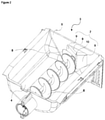
Figure 2 - is a side view of the container -
Figure 3 - is a side view of the container with the transfer means being removed - The following numerals are assigned to different parts demonstrated in the drawings and referred to in the present detailed description of the invention:
- 1. Ice maker assembly
- 2. Ice mold
- 3. Container
- 4. Bottom wall
- 5. Front wall
- 6. Transfer means
- 7. Guide
- 8. Channel
- 9. Surface
- 10. Apex
- The present invention relates to a cooling appliance comprising an ice maker assembly (1) wherein the ice maker assembly (1) comprises an ice mold (2) including plurality of cavities and configured to freeze water to produce ice pieces; a container (3) placed underneath the ice maker (2) and is configured to store the ice pieces, comprising; a bottom wall (4), a pair of side walls reciprocally extending from the bottom wall (4); a front wall (5) and a back wall configured to interconnect the said side walls; an transfer means (6) extending between the front wall (5) and the back wall which upon being activated, is configured to transfer ice pieces towards the front wall (5), wherein the front wall (5) comprises an opening.
- In the preferred embodiment of the invention, the cooling appliance comprises a guide (7) provided on the front wall (5), and comprising a cutout in line with the opening, forming a channel (8), and wherein the guide (7) is configured to guide ice pieces towards the channel (8) upon activation of the transfer means (6). The ice maker assembly (1) comprises at least one ice mold (2). The ice mold (2) comprises plurality of cavity filled by water by means of a water transfer means. The ice maker assembly (1) also comprises a motor that is utilized to twist the ice mold (2), forcing the ice pieces out of the ice mold (2) and into the container (3). The container (3) is in the form of an open top box and comprises; the bottom wall, two side walls, the front wall (5) and the back wall defining a storage volume. The transfer means (6) is placed inside the container (3) and longitudinally extends in between the front wall (5) and the back wall. The transfer means (6) is activated by means of a secondary motor and upon being activated, starts to transfer ice pieces stored inside the container (3) towards the front wall (5). In an embodiment, the transfer means (6) is an auger. The front wall (5) comprises the opening wherein the opening transfers the ice pieces out of the container (3). The ice pieces are then transmitted to an ice dispenser provided on a door of the cooling appliance The guide (7) is provided on the front wall (5) and comprises the cutout. The guide (7) is provided on the front wall (5) such that the cutout and the opening are configured to be in line with each other, therefore forming the channel (8) for ice pieces that are transferred by means of the transfer means (6) to be transferred out of the container (3). The guide (7) at least partly surrounds the opening and therefore the channel (8) and is utilized to guide the ice pieces towards the channel (8). By means of the guide (7), the ice pieces are prevented from getting stuck and crushed between the front wall (5) and the transfer means (6). This helps obtaining larger ice pieces and at the same time, mechanical stress on the transfer means (6) and the front wall (5) is significantly decreased, which in turn increases life time of the ice maker assembly (1).
- In the preferred embodiment of the invention, the guide (7) is configured to form a continuous surface with the front wall (5). By means of providing a continuous surface between the guide (7) and the front wall (5), ice pieces are prevented to jam in between an otherwise indented surface. Having a continuous surface also increases the flow of ice through the channel (8), increasing ice out take.
- In the preferred embodiment of the invention, the guide (7) is in the form a polygon, protruding towards the transfer means (6). The guide (7) having a polygon geometry helps deflect the ice pieces sideways upon activation of the transfer means (6). The ones that are deflected towards the channel (8) are then transmitted to the consumer. The rest remain inside the container (3) and are stored for future use. The guide (7) having polygonal form helps increase the ice out take of the ice maker assembly (1).
- In the preferred embodiment of the invention, the guide (7) comprises a plurality of surfaces (9) having normal vectors pointing different directions, wherein each surface (9) is configured to be engaged with at least a neighboring surface (9) along a linear line and to converge at an apex (10). By means of plurality of surfaces (9) having normal vectors pointing different directions, the ice pieces are prevented to get stuck on the surfaces (9) and instead the ice pieces are deflected according to the directions of the normal vectors. The apex (10) has a convex geometry and further decreases the possibility of ice pieces getting stuck in between the guide (7) and the transfer means (6).
- In the preferred embodiment of the invention, the transfer means (6) is configured to penetrate the guide (7). The transfer means (6) penetrates the guide (7) in close vicinity of the apex (10). By means of which, ice pieces are further prevented from getting crushed in between the guide (7) and the transfer means (6).
- In the preferred embodiment of the invention, the surfaces (9) and the front wall (5) form an acute angle in-between. The angle between the front wall (5) and the surfaces (9) lies in the range of 5 degrees to 30 degrees.
- In the preferred embodiment of the invention, the guide (7) is integral with the front wall (5). By producing the guide (7) integral with the front wall (5) provides a robust structure. Another advantageous effect provided by means of producing the guide (7) integral with the front wall (5) is that the mold related costs are decreased.
- In the preferred embodiment of the invention, the guide (7) is removable placed on to the front wall (5). By means of producing guide (7) as a separate part, allows the user to replace a broken guide (7) easily, therefore decreasing maintenance related costs.
- In the preferred embodiment of the invention, the surfaces (9) comprise plurality of linear protrusions pointing away from the apex (10). Each surface (9) comprises plurality of linear protrusions, starting in close vicinity of the apex (10) and stretch out as the distance to the apex (10) increases.
- An advantageous effect provided by means of the invention is that the ice pieces stored inside container (3) are prevented to get stuck in between the transfer means (6) and the front wall (5) upon activation of the transfer means (6) by means of the guide (7). This prevents the ice pieces from getting crushed, thus increasing the quality and size of ice pieces.
- Another advantageous effect provided by means of the ice pieces being prevented to get stuck in between the transfer means (6) and the front wall (5) is that the load on the motor activating the transfer means (6) is decreased, which in turn helps increase life time of the motor.
- Another advantageous effect provided by means of the ice pieces being prevented to get stuck in between the transfer means (6) and the front wall (5) is that the mechanical stress on the transfer means (6) and the front wall (5) is decreased. This helps reduce structural cracks on the transfer means (6) and the front wall (5) increasing life time of the said parts.
Claims (9)
- A cooling appliance comprising an ice maker assembly (1); the ice maker assembly () comprising;an ice mold (2) including plurality of cavities and configured to freeze water to produce ice pieces;a container (3) placed underneath the ice maker (2) and is configured to store the ice pieces, comprising;a bottom wall (4), a pair of side walls reciprocally extending from the bottom wall (4); a front wall (5) and a back wall configured to interconnect the said side walls;an transfer means (6) extending between the front wall (5) and the back wall which upon being activated, is configured to transfer ice pieces towards the front wall (5), wherein the front wall (5) comprises an opening,characterized bya guide (7) provided on the front wall (5), and comprising a cutout in line with the opening, forming a channel (8), and wherein the guide (7) is configured to guide ice pieces towards the channel (8) upon activation of the transfer means (6).
- A cooling appliance according to claim 1, characterized in that the guide (7) is configured to form a continuous surface with the front wall (5).
- A cooling appliance according to any preceding claim, characterized in that the guide (7) is in the form a polygon, protruding towards the transfer means (6).
- A cooling appliance according to any preceding claim, characterized in that the guide (7) comprises a plurality of surfaces (9) having normal vectors pointing different directions, wherein each surface (9) is configured to be engaged with at least a neighboring surface (9) along a linear line and to converge at an apex (10).
- A cooling appliance according to any preceding claim, characterized in that the transfer means (6) is configured to penetrate the guide (7).
- A cooling appliance according to claims 4 to 5, characterized in that the surfaces (9) and the front wall (5) form an acute angle in-between.
- A cooling appliance according to any preceding claim, characterized in that the guide (7) is integral with the front wall (5).
- A cooling appliance according to claims 1 to 7, characterized in that the guide (7) is removable placed on to the front wall (5).
- A cooling appliance according to claims 4 to 8, characterized in that the surfaces (9) comprise plurality of linear protrusions pointing away from the apex (10).
Applications Claiming Priority (1)
| Application Number | Priority Date | Filing Date | Title |
|---|---|---|---|
| TR2020/14680A TR202014680A2 (en) | 2020-09-16 | 2020-09-16 | Ice making system and the cooling device used |
Publications (2)
| Publication Number | Publication Date |
|---|---|
| EP3971498A1 true EP3971498A1 (en) | 2022-03-23 |
| EP3971498B1 EP3971498B1 (en) | 2024-06-26 |
Family
ID=77050866
Family Applications (1)
| Application Number | Title | Priority Date | Filing Date |
|---|---|---|---|
| EP21187572.9A Active EP3971498B1 (en) | 2020-09-16 | 2021-07-25 | A cooling appliance comprising an ice making assembly |
Country Status (2)
| Country | Link |
|---|---|
| EP (1) | EP3971498B1 (en) |
| TR (1) | TR202014680A2 (en) |
Citations (3)
| Publication number | Priority date | Publication date | Assignee | Title |
|---|---|---|---|---|
| US6952936B2 (en) | 2003-12-22 | 2005-10-11 | General Electric Company | Refrigerator and ice maker apparatus |
| US20110126576A1 (en) * | 2009-11-30 | 2011-06-02 | Lg Electronics Inc. | Ice storage device and refrigerator including the same and an water purifier including the same |
| US20190204001A1 (en) * | 2017-12-08 | 2019-07-04 | Midea Group Co., Ltd. | Refrigerator icemaking system with tandem storage bins and/or removable dispenser recess |
-
2020
- 2020-09-16 TR TR2020/14680A patent/TR202014680A2/en unknown
-
2021
- 2021-07-25 EP EP21187572.9A patent/EP3971498B1/en active Active
Patent Citations (3)
| Publication number | Priority date | Publication date | Assignee | Title |
|---|---|---|---|---|
| US6952936B2 (en) | 2003-12-22 | 2005-10-11 | General Electric Company | Refrigerator and ice maker apparatus |
| US20110126576A1 (en) * | 2009-11-30 | 2011-06-02 | Lg Electronics Inc. | Ice storage device and refrigerator including the same and an water purifier including the same |
| US20190204001A1 (en) * | 2017-12-08 | 2019-07-04 | Midea Group Co., Ltd. | Refrigerator icemaking system with tandem storage bins and/or removable dispenser recess |
Also Published As
| Publication number | Publication date |
|---|---|
| TR202014680A2 (en) | 2022-03-21 |
| EP3971498B1 (en) | 2024-06-26 |
Similar Documents
| Publication | Publication Date | Title |
|---|---|---|
| EP3293473B2 (en) | Refrigerator | |
| US10006689B2 (en) | Modular bucket and door architecture to deliver three ice functions | |
| EP1835244A2 (en) | Refrigerator having an ice maker and ice dispenser | |
| US20110146324A1 (en) | Refrigerator | |
| WO2019242375A1 (en) | Ice storage box and refrigerator having same | |
| KR20080065435A (en) | Ice Guide for Refrigerator | |
| EP3971498B1 (en) | A cooling appliance comprising an ice making assembly | |
| US3021035A (en) | Ice dispenser for beverage vending machines | |
| US20200300528A1 (en) | Ice bucket assembly for producing nugget ice for refrigerator appliance | |
| US20060065008A1 (en) | Refrigerator | |
| US9212840B2 (en) | Apparatus for pelletizing ice within a refrigerator | |
| EP2333462B1 (en) | Three forms of ice from a single well | |
| US7387507B2 (en) | Scoop for ice cream and the like | |
| US9903632B2 (en) | Ice well diverter wedge for ice container | |
| CN109312972B (en) | Ice storage device | |
| US7257962B2 (en) | Ice transfer device for refrigerator | |
| KR101632214B1 (en) | An ice container comprising a rotating blade with an reinforced structure and a refrigerator comprising the same | |
| US20100011797A1 (en) | Refrigerator and ice reservoir container for it | |
| CN111829239A (en) | Ice crusher and refrigerator | |
| US3690120A (en) | Stationary mold ice maker with the bottom ejector | |
| KR20080016370A (en) | Refrigerator | |
| CN111829236A (en) | Ice crusher and refrigerator | |
| WO2012062583A2 (en) | Refrigerating device having an ice dispenser | |
| KR100775118B1 (en) | Refrigerator ice maker | |
| KR20070115003A (en) | Refrigerator ice maker |
Legal Events
| Date | Code | Title | Description |
|---|---|---|---|
| PUAI | Public reference made under article 153(3) epc to a published international application that has entered the european phase |
Free format text: ORIGINAL CODE: 0009012 |
|
| STAA | Information on the status of an ep patent application or granted ep patent |
Free format text: STATUS: REQUEST FOR EXAMINATION WAS MADE |
|
| 17P | Request for examination filed |
Effective date: 20210725 |
|
| AK | Designated contracting states |
Kind code of ref document: A1 Designated state(s): AL AT BE BG CH CY CZ DE DK EE ES FI FR GB GR HR HU IE IS IT LI LT LU LV MC MK MT NL NO PL PT RO RS SE SI SK SM TR |
|
| STAA | Information on the status of an ep patent application or granted ep patent |
Free format text: STATUS: EXAMINATION IS IN PROGRESS |
|
| 17Q | First examination report despatched |
Effective date: 20221031 |
|
| GRAP | Despatch of communication of intention to grant a patent |
Free format text: ORIGINAL CODE: EPIDOSNIGR1 |
|
| STAA | Information on the status of an ep patent application or granted ep patent |
Free format text: STATUS: GRANT OF PATENT IS INTENDED |
|
| RIC1 | Information provided on ipc code assigned before grant |
Ipc: F25C 5/182 20180101ALN20240212BHEP Ipc: F25C 5/20 20180101AFI20240212BHEP |
|
| RIC1 | Information provided on ipc code assigned before grant |
Ipc: F25C 5/182 20180101ALN20240218BHEP Ipc: F25C 5/20 20180101AFI20240218BHEP |
|
| INTG | Intention to grant announced |
Effective date: 20240305 |
|
| GRAS | Grant fee paid |
Free format text: ORIGINAL CODE: EPIDOSNIGR3 |
|
| GRAA | (expected) grant |
Free format text: ORIGINAL CODE: 0009210 |
|
| STAA | Information on the status of an ep patent application or granted ep patent |
Free format text: STATUS: THE PATENT HAS BEEN GRANTED |
|
| AK | Designated contracting states |
Kind code of ref document: B1 Designated state(s): AL AT BE BG CH CY CZ DE DK EE ES FI FR GB GR HR HU IE IS IT LI LT LU LV MC MK MT NL NO PL PT RO RS SE SI SK SM TR |
|
| REG | Reference to a national code |
Ref country code: GB Ref legal event code: FG4D |
|
| REG | Reference to a national code |
Ref country code: CH Ref legal event code: EP |
|
| REG | Reference to a national code |
Ref country code: DE Ref legal event code: R096 Ref document number: 602021014730 Country of ref document: DE |
|
| PG25 | Lapsed in a contracting state [announced via postgrant information from national office to epo] |
Ref country code: BG Free format text: LAPSE BECAUSE OF FAILURE TO SUBMIT A TRANSLATION OF THE DESCRIPTION OR TO PAY THE FEE WITHIN THE PRESCRIBED TIME-LIMIT Effective date: 20240626 |
|
| PG25 | Lapsed in a contracting state [announced via postgrant information from national office to epo] |
Ref country code: FI Free format text: LAPSE BECAUSE OF FAILURE TO SUBMIT A TRANSLATION OF THE DESCRIPTION OR TO PAY THE FEE WITHIN THE PRESCRIBED TIME-LIMIT Effective date: 20240626 Ref country code: HR Free format text: LAPSE BECAUSE OF FAILURE TO SUBMIT A TRANSLATION OF THE DESCRIPTION OR TO PAY THE FEE WITHIN THE PRESCRIBED TIME-LIMIT Effective date: 20240626 |
|
| REG | Reference to a national code |
Ref country code: LT Ref legal event code: MG9D |
|
| PG25 | Lapsed in a contracting state [announced via postgrant information from national office to epo] |
Ref country code: GR Free format text: LAPSE BECAUSE OF FAILURE TO SUBMIT A TRANSLATION OF THE DESCRIPTION OR TO PAY THE FEE WITHIN THE PRESCRIBED TIME-LIMIT Effective date: 20240927 |
|
| PG25 | Lapsed in a contracting state [announced via postgrant information from national office to epo] |
Ref country code: LV Free format text: LAPSE BECAUSE OF FAILURE TO SUBMIT A TRANSLATION OF THE DESCRIPTION OR TO PAY THE FEE WITHIN THE PRESCRIBED TIME-LIMIT Effective date: 20240626 |
|
| REG | Reference to a national code |
Ref country code: NL Ref legal event code: MP Effective date: 20240626 |
|
| PG25 | Lapsed in a contracting state [announced via postgrant information from national office to epo] |
Ref country code: NO Free format text: LAPSE BECAUSE OF FAILURE TO SUBMIT A TRANSLATION OF THE DESCRIPTION OR TO PAY THE FEE WITHIN THE PRESCRIBED TIME-LIMIT Effective date: 20240926 Ref country code: LV Free format text: LAPSE BECAUSE OF FAILURE TO SUBMIT A TRANSLATION OF THE DESCRIPTION OR TO PAY THE FEE WITHIN THE PRESCRIBED TIME-LIMIT Effective date: 20240626 Ref country code: HR Free format text: LAPSE BECAUSE OF FAILURE TO SUBMIT A TRANSLATION OF THE DESCRIPTION OR TO PAY THE FEE WITHIN THE PRESCRIBED TIME-LIMIT Effective date: 20240626 Ref country code: GR Free format text: LAPSE BECAUSE OF FAILURE TO SUBMIT A TRANSLATION OF THE DESCRIPTION OR TO PAY THE FEE WITHIN THE PRESCRIBED TIME-LIMIT Effective date: 20240927 Ref country code: FI Free format text: LAPSE BECAUSE OF FAILURE TO SUBMIT A TRANSLATION OF THE DESCRIPTION OR TO PAY THE FEE WITHIN THE PRESCRIBED TIME-LIMIT Effective date: 20240626 Ref country code: BG Free format text: LAPSE BECAUSE OF FAILURE TO SUBMIT A TRANSLATION OF THE DESCRIPTION OR TO PAY THE FEE WITHIN THE PRESCRIBED TIME-LIMIT Effective date: 20240626 Ref country code: RS Free format text: LAPSE BECAUSE OF FAILURE TO SUBMIT A TRANSLATION OF THE DESCRIPTION OR TO PAY THE FEE WITHIN THE PRESCRIBED TIME-LIMIT Effective date: 20240926 |
|
| PG25 | Lapsed in a contracting state [announced via postgrant information from national office to epo] |
Ref country code: NL Free format text: LAPSE BECAUSE OF FAILURE TO SUBMIT A TRANSLATION OF THE DESCRIPTION OR TO PAY THE FEE WITHIN THE PRESCRIBED TIME-LIMIT Effective date: 20240626 |
|
| REG | Reference to a national code |
Ref country code: AT Ref legal event code: MK05 Ref document number: 1698020 Country of ref document: AT Kind code of ref document: T Effective date: 20240626 |
|
| PG25 | Lapsed in a contracting state [announced via postgrant information from national office to epo] |
Ref country code: NL Free format text: LAPSE BECAUSE OF FAILURE TO SUBMIT A TRANSLATION OF THE DESCRIPTION OR TO PAY THE FEE WITHIN THE PRESCRIBED TIME-LIMIT Effective date: 20240626 |
|
| PG25 | Lapsed in a contracting state [announced via postgrant information from national office to epo] |
Ref country code: PT Free format text: LAPSE BECAUSE OF FAILURE TO SUBMIT A TRANSLATION OF THE DESCRIPTION OR TO PAY THE FEE WITHIN THE PRESCRIBED TIME-LIMIT Effective date: 20241028 |
|
| PG25 | Lapsed in a contracting state [announced via postgrant information from national office to epo] |
Ref country code: PT Free format text: LAPSE BECAUSE OF FAILURE TO SUBMIT A TRANSLATION OF THE DESCRIPTION OR TO PAY THE FEE WITHIN THE PRESCRIBED TIME-LIMIT Effective date: 20241028 |
|
| PG25 | Lapsed in a contracting state [announced via postgrant information from national office to epo] |
Ref country code: PL Free format text: LAPSE BECAUSE OF FAILURE TO SUBMIT A TRANSLATION OF THE DESCRIPTION OR TO PAY THE FEE WITHIN THE PRESCRIBED TIME-LIMIT Effective date: 20240626 |
|
| PG25 | Lapsed in a contracting state [announced via postgrant information from national office to epo] |
Ref country code: EE Free format text: LAPSE BECAUSE OF FAILURE TO SUBMIT A TRANSLATION OF THE DESCRIPTION OR TO PAY THE FEE WITHIN THE PRESCRIBED TIME-LIMIT Effective date: 20240626 |
|
| PG25 | Lapsed in a contracting state [announced via postgrant information from national office to epo] |
Ref country code: IS Free format text: LAPSE BECAUSE OF FAILURE TO SUBMIT A TRANSLATION OF THE DESCRIPTION OR TO PAY THE FEE WITHIN THE PRESCRIBED TIME-LIMIT Effective date: 20241026 Ref country code: AT Free format text: LAPSE BECAUSE OF FAILURE TO SUBMIT A TRANSLATION OF THE DESCRIPTION OR TO PAY THE FEE WITHIN THE PRESCRIBED TIME-LIMIT Effective date: 20240626 |
|
| PG25 | Lapsed in a contracting state [announced via postgrant information from national office to epo] |
Ref country code: CZ Free format text: LAPSE BECAUSE OF FAILURE TO SUBMIT A TRANSLATION OF THE DESCRIPTION OR TO PAY THE FEE WITHIN THE PRESCRIBED TIME-LIMIT Effective date: 20240626 |
|
| PG25 | Lapsed in a contracting state [announced via postgrant information from national office to epo] |
Ref country code: RO Free format text: LAPSE BECAUSE OF FAILURE TO SUBMIT A TRANSLATION OF THE DESCRIPTION OR TO PAY THE FEE WITHIN THE PRESCRIBED TIME-LIMIT Effective date: 20240626 Ref country code: SK Free format text: LAPSE BECAUSE OF FAILURE TO SUBMIT A TRANSLATION OF THE DESCRIPTION OR TO PAY THE FEE WITHIN THE PRESCRIBED TIME-LIMIT Effective date: 20240626 |
|
| PG25 | Lapsed in a contracting state [announced via postgrant information from national office to epo] |
Ref country code: SM Free format text: LAPSE BECAUSE OF FAILURE TO SUBMIT A TRANSLATION OF THE DESCRIPTION OR TO PAY THE FEE WITHIN THE PRESCRIBED TIME-LIMIT Effective date: 20240626 Ref country code: ES Free format text: LAPSE BECAUSE OF FAILURE TO SUBMIT A TRANSLATION OF THE DESCRIPTION OR TO PAY THE FEE WITHIN THE PRESCRIBED TIME-LIMIT Effective date: 20240626 |
|
| PG25 | Lapsed in a contracting state [announced via postgrant information from national office to epo] |
Ref country code: SM Free format text: LAPSE BECAUSE OF FAILURE TO SUBMIT A TRANSLATION OF THE DESCRIPTION OR TO PAY THE FEE WITHIN THE PRESCRIBED TIME-LIMIT Effective date: 20240626 Ref country code: SK Free format text: LAPSE BECAUSE OF FAILURE TO SUBMIT A TRANSLATION OF THE DESCRIPTION OR TO PAY THE FEE WITHIN THE PRESCRIBED TIME-LIMIT Effective date: 20240626 Ref country code: RO Free format text: LAPSE BECAUSE OF FAILURE TO SUBMIT A TRANSLATION OF THE DESCRIPTION OR TO PAY THE FEE WITHIN THE PRESCRIBED TIME-LIMIT Effective date: 20240626 Ref country code: PL Free format text: LAPSE BECAUSE OF FAILURE TO SUBMIT A TRANSLATION OF THE DESCRIPTION OR TO PAY THE FEE WITHIN THE PRESCRIBED TIME-LIMIT Effective date: 20240626 Ref country code: IS Free format text: LAPSE BECAUSE OF FAILURE TO SUBMIT A TRANSLATION OF THE DESCRIPTION OR TO PAY THE FEE WITHIN THE PRESCRIBED TIME-LIMIT Effective date: 20241026 Ref country code: ES Free format text: LAPSE BECAUSE OF FAILURE TO SUBMIT A TRANSLATION OF THE DESCRIPTION OR TO PAY THE FEE WITHIN THE PRESCRIBED TIME-LIMIT Effective date: 20240626 Ref country code: EE Free format text: LAPSE BECAUSE OF FAILURE TO SUBMIT A TRANSLATION OF THE DESCRIPTION OR TO PAY THE FEE WITHIN THE PRESCRIBED TIME-LIMIT Effective date: 20240626 Ref country code: CZ Free format text: LAPSE BECAUSE OF FAILURE TO SUBMIT A TRANSLATION OF THE DESCRIPTION OR TO PAY THE FEE WITHIN THE PRESCRIBED TIME-LIMIT Effective date: 20240626 Ref country code: AT Free format text: LAPSE BECAUSE OF FAILURE TO SUBMIT A TRANSLATION OF THE DESCRIPTION OR TO PAY THE FEE WITHIN THE PRESCRIBED TIME-LIMIT Effective date: 20240626 |
|
| PG25 | Lapsed in a contracting state [announced via postgrant information from national office to epo] |
Ref country code: IT Free format text: LAPSE BECAUSE OF FAILURE TO SUBMIT A TRANSLATION OF THE DESCRIPTION OR TO PAY THE FEE WITHIN THE PRESCRIBED TIME-LIMIT Effective date: 20240626 |
|
| REG | Reference to a national code |
Ref country code: CH Ref legal event code: PL |
|
| PG25 | Lapsed in a contracting state [announced via postgrant information from national office to epo] |
Ref country code: LU Free format text: LAPSE BECAUSE OF NON-PAYMENT OF DUE FEES Effective date: 20240725 |
|
| PG25 | Lapsed in a contracting state [announced via postgrant information from national office to epo] |
Ref country code: MC Free format text: LAPSE BECAUSE OF FAILURE TO SUBMIT A TRANSLATION OF THE DESCRIPTION OR TO PAY THE FEE WITHIN THE PRESCRIBED TIME-LIMIT Effective date: 20240626 |
|
| REG | Reference to a national code |
Ref country code: DE Ref legal event code: R097 Ref document number: 602021014730 Country of ref document: DE |
|
| PG25 | Lapsed in a contracting state [announced via postgrant information from national office to epo] |
Ref country code: MC Free format text: LAPSE BECAUSE OF FAILURE TO SUBMIT A TRANSLATION OF THE DESCRIPTION OR TO PAY THE FEE WITHIN THE PRESCRIBED TIME-LIMIT Effective date: 20240626 Ref country code: LU Free format text: LAPSE BECAUSE OF NON-PAYMENT OF DUE FEES Effective date: 20240725 |
|
| PG25 | Lapsed in a contracting state [announced via postgrant information from national office to epo] |
Ref country code: DK Free format text: LAPSE BECAUSE OF FAILURE TO SUBMIT A TRANSLATION OF THE DESCRIPTION OR TO PAY THE FEE WITHIN THE PRESCRIBED TIME-LIMIT Effective date: 20240626 |
|
| PG25 | Lapsed in a contracting state [announced via postgrant information from national office to epo] |
Ref country code: BE Free format text: LAPSE BECAUSE OF NON-PAYMENT OF DUE FEES Effective date: 20240731 Ref country code: CH Free format text: LAPSE BECAUSE OF NON-PAYMENT OF DUE FEES Effective date: 20240731 |
|
| PLBE | No opposition filed within time limit |
Free format text: ORIGINAL CODE: 0009261 |
|
| STAA | Information on the status of an ep patent application or granted ep patent |
Free format text: STATUS: NO OPPOSITION FILED WITHIN TIME LIMIT |
|
| 26N | No opposition filed |
Effective date: 20250327 |
|
| REG | Reference to a national code |
Ref country code: BE Ref legal event code: MM Effective date: 20240731 |
|
| PG25 | Lapsed in a contracting state [announced via postgrant information from national office to epo] |
Ref country code: IE Free format text: LAPSE BECAUSE OF NON-PAYMENT OF DUE FEES Effective date: 20240725 |
|
| PG25 | Lapsed in a contracting state [announced via postgrant information from national office to epo] |
Ref country code: SE Free format text: LAPSE BECAUSE OF FAILURE TO SUBMIT A TRANSLATION OF THE DESCRIPTION OR TO PAY THE FEE WITHIN THE PRESCRIBED TIME-LIMIT Effective date: 20240626 |
|
| PGFP | Annual fee paid to national office [announced via postgrant information from national office to epo] |
Ref country code: DE Payment date: 20250722 Year of fee payment: 5 |
|
| PGFP | Annual fee paid to national office [announced via postgrant information from national office to epo] |
Ref country code: TR Payment date: 20250704 Year of fee payment: 5 |
|
| PGFP | Annual fee paid to national office [announced via postgrant information from national office to epo] |
Ref country code: FR Payment date: 20250725 Year of fee payment: 5 |
|
| PG25 | Lapsed in a contracting state [announced via postgrant information from national office to epo] |
Ref country code: CY Free format text: LAPSE BECAUSE OF FAILURE TO SUBMIT A TRANSLATION OF THE DESCRIPTION OR TO PAY THE FEE WITHIN THE PRESCRIBED TIME-LIMIT; INVALID AB INITIO Effective date: 20210725 |
|
| PG25 | Lapsed in a contracting state [announced via postgrant information from national office to epo] |
Ref country code: HU Free format text: LAPSE BECAUSE OF FAILURE TO SUBMIT A TRANSLATION OF THE DESCRIPTION OR TO PAY THE FEE WITHIN THE PRESCRIBED TIME-LIMIT; INVALID AB INITIO Effective date: 20210725 |
|
| GBPC | Gb: european patent ceased through non-payment of renewal fee |
Effective date: 20250725 |
|
| PG25 | Lapsed in a contracting state [announced via postgrant information from national office to epo] |
Ref country code: GB Free format text: LAPSE BECAUSE OF NON-PAYMENT OF DUE FEES Effective date: 20250725 |
|
| PG25 | Lapsed in a contracting state [announced via postgrant information from national office to epo] |
Ref country code: SI Free format text: LAPSE BECAUSE OF FAILURE TO SUBMIT A TRANSLATION OF THE DESCRIPTION OR TO PAY THE FEE WITHIN THE PRESCRIBED TIME-LIMIT Effective date: 20240626 |
|
| PG25 | Lapsed in a contracting state [announced via postgrant information from national office to epo] |
Ref country code: LT Free format text: LAPSE BECAUSE OF FAILURE TO SUBMIT A TRANSLATION OF THE DESCRIPTION OR TO PAY THE FEE WITHIN THE PRESCRIBED TIME-LIMIT Effective date: 20240626 |