EP3971491A1 - Driving device for air deflector of air conditioner and air conditioner - Google Patents
Driving device for air deflector of air conditioner and air conditioner Download PDFInfo
- Publication number
- EP3971491A1 EP3971491A1 EP21153973.9A EP21153973A EP3971491A1 EP 3971491 A1 EP3971491 A1 EP 3971491A1 EP 21153973 A EP21153973 A EP 21153973A EP 3971491 A1 EP3971491 A1 EP 3971491A1
- Authority
- EP
- European Patent Office
- Prior art keywords
- transmission shaft
- gear
- air conditioner
- shaft
- link plate
- Prior art date
- Legal status (The legal status is an assumption and is not a legal conclusion. Google has not performed a legal analysis and makes no representation as to the accuracy of the status listed.)
- Granted
Links
Images





Classifications
-
- F—MECHANICAL ENGINEERING; LIGHTING; HEATING; WEAPONS; BLASTING
- F24—HEATING; RANGES; VENTILATING
- F24F—AIR-CONDITIONING; AIR-HUMIDIFICATION; VENTILATION; USE OF AIR CURRENTS FOR SCREENING
- F24F13/00—Details common to, or for air-conditioning, air-humidification, ventilation or use of air currents for screening
- F24F13/08—Air-flow control members, e.g. louvres, grilles, flaps or guide plates
- F24F13/10—Air-flow control members, e.g. louvres, grilles, flaps or guide plates movable, e.g. dampers
- F24F13/14—Air-flow control members, e.g. louvres, grilles, flaps or guide plates movable, e.g. dampers built up of tilting members, e.g. louvre
- F24F13/1426—Air-flow control members, e.g. louvres, grilles, flaps or guide plates movable, e.g. dampers built up of tilting members, e.g. louvre characterised by actuating means
-
- F—MECHANICAL ENGINEERING; LIGHTING; HEATING; WEAPONS; BLASTING
- F24—HEATING; RANGES; VENTILATING
- F24F—AIR-CONDITIONING; AIR-HUMIDIFICATION; VENTILATION; USE OF AIR CURRENTS FOR SCREENING
- F24F13/00—Details common to, or for air-conditioning, air-humidification, ventilation or use of air currents for screening
- F24F13/08—Air-flow control members, e.g. louvres, grilles, flaps or guide plates
- F24F13/10—Air-flow control members, e.g. louvres, grilles, flaps or guide plates movable, e.g. dampers
- F24F13/14—Air-flow control members, e.g. louvres, grilles, flaps or guide plates movable, e.g. dampers built up of tilting members, e.g. louvre
- F24F13/1426—Air-flow control members, e.g. louvres, grilles, flaps or guide plates movable, e.g. dampers built up of tilting members, e.g. louvre characterised by actuating means
- F24F2013/1433—Air-flow control members, e.g. louvres, grilles, flaps or guide plates movable, e.g. dampers built up of tilting members, e.g. louvre characterised by actuating means with electric motors
-
- F—MECHANICAL ENGINEERING; LIGHTING; HEATING; WEAPONS; BLASTING
- F24—HEATING; RANGES; VENTILATING
- F24F—AIR-CONDITIONING; AIR-HUMIDIFICATION; VENTILATION; USE OF AIR CURRENTS FOR SCREENING
- F24F13/00—Details common to, or for air-conditioning, air-humidification, ventilation or use of air currents for screening
- F24F13/08—Air-flow control members, e.g. louvres, grilles, flaps or guide plates
- F24F13/10—Air-flow control members, e.g. louvres, grilles, flaps or guide plates movable, e.g. dampers
- F24F13/14—Air-flow control members, e.g. louvres, grilles, flaps or guide plates movable, e.g. dampers built up of tilting members, e.g. louvre
- F24F13/1426—Air-flow control members, e.g. louvres, grilles, flaps or guide plates movable, e.g. dampers built up of tilting members, e.g. louvre characterised by actuating means
- F24F2013/1446—Air-flow control members, e.g. louvres, grilles, flaps or guide plates movable, e.g. dampers built up of tilting members, e.g. louvre characterised by actuating means with gearings
Definitions
- the present disclosure relates to the technical field of an air conditioner, and more particularly, to a driving device for an air deflector of an air conditioner and an air conditioner.
- an air outlet of an air conditioner on the market is provided with an air deflector of the air conditioner.
- the air deflector of the air conditioner will seal the air outlet, thus effectively preventing dust and water vapor from entering the air conditioner and also ensuring an aesthetic appearance of the air conditioner.
- the air deflector of the air conditioner may adjust an air direction to avoid a direct blowing. That is, the air deflector of the air conditioner may change an air blowing direction to avoid blowing directly to a human body, so as to reduce adverse effects on a human health due to the direct blowing.
- the air deflector of the existing air outlet of the air conditioner mounted on a wall is mostly an integral structure, and is driven by a motor to rotate and change the air blowing direction, which however has a limited effect on a degree of a change in the air direction. Therefore, the whole air deflector of the air conditioner is divided into two separate air deflectors, and the two air deflectors rotate simultaneously, which may better change the air blowing direction of the air outlet of the air conditioner.
- two motors are selected to drive the two air deflectors, respectively, the cost and the power consumption are relatively high, which is not conducive to the protection of environment.
- it is necessary to propose a driving device for an air deflector of an air conditioner and an air conditioner so as to at least partially solve the problems existing in the prior art.
- a driving device for an air deflector of an air conditioner including: a motor, a fixing plate, a first transmission shaft and a second transmission shaft.
- the motor is connected with a side of the fixing plate, the first transmission shaft and the second transmission shaft are arranged at a side of the fixing plate away from the motor, and the second transmission shaft is arranged above the first transmission shaft.
- the first transmission shaft is fixedly connected with the motor, the second transmission shaft is rotatably connected with the fixing plate, and the first transmission shaft is connected with the second transmission shaft through a linkage mechanism.
- the linkage mechanism includes a first gear, a second gear and a gear shaft, the first gear and the first transmission shaft are arranged coaxially, the second gear and the second transmission shaft are arranged coaxially, the gear shaft is arranged between the first gear and the second gear, the gear shaft is rotatably connected with the fixing plate, a third gear is arranged to the gear shaft, and the first gear and the second gear are meshed and connected with the third gear, respectively.
- an end face of the third gear adjacent to the fixing plate is fixedly connected with a first shaft body, an end face of the first shaft body away from the third gear is fixedly connected with a first connecting portion, the fixing plate is provided with a first round hole corresponding to the first connecting portion, an end face of the first connecting portion away from the first shaft body is fixedly connected with a first tapered head, and a first U-shaped groove is formed in the first tapered head.
- the linkage mechanism includes a first link plate, a second link plate and a third link plate, the first link plate is arranged to the first transmission shaft, the second link plate is arranged to the second transmission shaft, the third link plate is arranged between the first link plate and the second link plate, one end of the third link plate is hinged with an end of the first link plate away from the first transmission shaft, and the other end thereof is hinged with an end of the second link plate away from the second transmission shaft.
- the third link plate includes a main plate provided with a first reinforcing rib thereon.
- a second round hole is formed in the end of the first link plate away from the first transmission shaft
- a third round hole is formed in the end of the second link plate away from the second transmission shaft
- one end of the main plate is provided with a first boss corresponding to the second round hole
- the other end of the main plate is provided with a second boss corresponding to the third round hole
- an end face of the first boss away from the main plate is fixedly connected with a second tapered head
- a second U-shaped groove is formed in the second tapered head
- an end face of the second boss away from the main plate is fixedly connected with a third tapered head
- a third U-shaped groove is formed in the third tapered head.
- the motor includes a motor main body and an output shaft, the output shaft is connected with the motor main body, the motor main body is fixedly connected with the fixing plate, the output shaft is fixedly connected with the first transmission shaft, and the fixing plate is provided with a fourth round hole corresponding to the output shaft.
- the first transmission shaft includes a second shaft body, and a center portion of one end face of the second shaft body adjacent to the fixing plate is provided with an aperture corresponding to the output shaft, and the other end face of the second shaft body is fixedly connected with a second connecting portion.
- a fifth round hole is arranged above the fourth round hole, the fifth round hole is formed in the fixing plate, the second transmission shaft is provided with a third connecting portion corresponding to the fifth round hole, one end face of the third connecting portion away from the motor is fixedly connected with a third shaft body, the other end face thereof is fixedly connected with a fourth tapered head, a fourth U-shaped groove is formed in the fourth tapered head, and an end face of the third shaft body away from the third connecting portion is fixedly connected with a fourth connecting portion.
- the fixing plate is provided with a second reinforcing rib thereon.
- the present disclosure provides according to a second aspect an air conditioner, including the driving device according to the first aspect of the present disclosure for the air deflector of the air conditioner.
- the present disclosure at least includes following significant effects.
- the present disclosure drives the first transmission shaft and the second transmission shaft to rotate through the one motor, and thus drives two air deflectors of the air conditioner respectively connected with the first transmission shaft and the second transmission shaft to rotate, so as to more effectively adjust the air blowing direction of the air outlet of the air conditioner, such that the present disclosure has the advantages of a low cost, a low power consumption, a contribution to environmental protection, a simple structure and a reliable power transmission.
- the present disclosure provides a driving device for an air deflector of an air conditioner, which includes a motor 1, a fixing plate 2, a first transmission shaft 3 and a second transmission shaft 4.
- the motor 1 is connected to a side of the fixing plate 2, the first transmission shaft 3 and the second transmission shaft 4 are arranged to another side of the fixing plate 2 away from the motor 1, and the second transmission shaft 4 is arranged above the first transmission shaft 3.
- the first transmission shaft 3 is fixedly connected with the motor 1
- the second transmission shaft 4 is rotatably connected with the fixing plate 2
- the first transmission shaft 3 is connected with the second transmission shaft 4 through a linkage mechanism.
- the motor 1 drives the first transmission shaft 3 to rotate
- the first transmission shaft 3 drives the second transmission shaft 4 to rotate through the linkage mechanism
- an end of the first transmission shaft 3 away from the fixing plate 2 is connected with one of two air deflectors 11 of the air conditioner, and drives this air deflector 11 of the air conditioner to rotate
- an end of the second transmission shaft 4 away from the fixing plate 2 is connected with the other one of the two air deflectors 11 of the air conditioner, and drives this air deflector 11 of the air conditioner to rotate.
- the present disclosure drives the first transmission shaft 3 to rotate through the one motor 1, and drives the second transmission shaft 4 to rotate through the linkage mechanism, so as to drive the two air deflectors 11 of the air conditioner respectively connected with the first transmission shaft 3 and the second transmission shaft 4 to rotate, thus more effectively adjusting an air blowing direction of an air outlet 13 of the air conditioner, such that the present disclosure has the advantages of a low cost, a low power consumption, a contribution to environmental protection, a simple structure and a reliable power transmission.
- Figs. 1-6 and 13-14 illustrate a first technical solution for the connection of the first transmission shaft and the second transmission shaft.
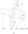
- the linkage mechanism includes a first gear 5, a second gear 6 and a gear shaft 7, the first gear 5 and the first transmission shaft 3 are arranged coaxially, the second gear 6 and the second transmission shaft 4 are arranged coaxially, the gear shaft 7 is arranged between the first gear 5 and the second gear 6, the gear shaft 7 is rotatably connected with the fixing plate 2, a third gear 7-1 is arranged on the gear shaft 7, and the first gear 5 and the second gear 6 are meshed and connected with the third gear 7-1, respectively.
- the working principle of the above technical solution is described as follows.
- the first gear 5, the second gear 6, and the third gear 7-1 have the same thickness and are spaced from the fixing plate 2 by the same clearance.
- the first transmission shaft 3 drives the first gear 5 to rotate, the first gear 5 is meshed with the third gear 7-1, and thus the first gear 5 drives the gear shaft 7 to rotate.
- the second gear 6 is meshed with the third gear 7-1, and thus the second gear 6 is driven to rotate.
- the second gear 6 drives the second transmission shaft 4 to rotate.
- the first gear 5, the second gear 6 and the gear shaft 7 may be arranged on a straight line or in a triangle according to actual needs.
- the first transmission shaft 3 effectively drives the second transmission shaft 4 to rotate through the first gear 5, the second gear 6 and the gear shaft 7.
- an end face of the third gear 7-1 adjacent to the fixing plate 2 is fixedly connected with a first shaft body 7-2, an end face of the first shaft body 7-2 away from the third gear 7-1 is fixedly connected with a first connecting portion 7-3, the fixing plate 2 is provided with a first round hole 2-1 corresponding to the first connecting portion 7-3, an end face of the first connecting portion 7-3 away from the first shaft body 7-2 is fixedly connected with a first tapered head 7-4, and a first U-shaped groove 7-4-1 is formed in the first tapered head 7-4.
- the fixing plate 2 is provided with the first round hole 2-1 corresponding to the first connecting portion 7-3, that is, a diameter and a hole depth of the first round hole 2-1 correspond to a diameter and a length of the first connecting portion 7-3, respectively, and the first connecting portion 7-3 is fitted in the first round hole 2-1 with a clearance, such that the first connecting portion 7-3 may rotate in the first round hole 2-1.
- the first round hole 2-1 limits the degree of freedom of the first connecting portion 7-3 moving forward and back as well as up and down.
- the third gear 7-1, the first shaft body 7-2, the first connecting portion 7-3 and the first tapered head 7-4 are coaxially arranged, a diameter of the first shaft body 7-2 is greater than that of the first connecting portion 7-3, and a sectional diameter of the first tapered head 7-4 adjacent to the fixing plate 2 is greater than the diameter of the first connecting portion 7-3.
- the degree of freedom of the first connecting portion 7-3 translating left and right is limited, and the degree of freedom of the first connecting portion 7-3 moving forward and back as well as up and down is also limited by the first round hole 2-1, such that the first connecting portion 7-3 may only rotate freely in the first round hole 2-1.
- a sectional diameter of the first tapered head 7-4 away from the fixing plate 2 is smaller than the diameter of the first connecting portion 7-3, a first U-shaped groove 7-4-1 is formed the first tapered head 7-4, an opening of the first U-shaped groove 7-4-1 faces towards a side away from the fixing plate 2, a bottom of the first U-shaped groove 7-4-1 extends to an end of the first connecting portion 7-3 adjacent to the first tapered head 7-4, and the first tapered head 7-4 deforms to have a smaller diameter while the first tapered head 7-4 is extending into or out of the first round hole 2-1, so as to facilitate the assembling and disassembling of the gear shaft 7 and the fixing plate 2.
- the above technical solution has following beneficial effects.
- the gear shaft 7 rotates freely in the first round hole 2-1 of the fixing plate 2 along its axial direction, the first transmission shaft 3 drives the first gear 5 to rotate, the first gear 5 drives the gear shaft 7 to rotate through the third gear 7-1, the gear shaft 7 drives the second gear 6 to rotate through the third gear 7-1, and the second gear 6 drives the second transmission shaft 4 to rotate, such that the first transmission shaft 3 effectively transfers the power to the second transmission shaft 4, and the gear shaft 7 and the fixing plate 2 are easy to disassemble and assemble.
- Figs. 7-14 illustrate a second technical solution for the connection of the first transmission shaft 3 and the second transmission shaft 4.
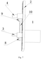
- the linkage mechanism includes a first link plate 8, a second link plate 9 and a third link plate 10, the first link plate 8 is arranged to the first transmission shaft 3, the second link plate 9 is arranged to the second transmission shaft 4, and the third link plate 10 is arranged between the first link plate 8 and the second link plate 9.
- One end of the third link plate 10 is hinged with an end of the first link plate 8 away from the first transmission shaft 3, and the other end thereof is hinged with an end of the second link plate 9 away from the second transmission shaft 4.
- the first link plate 8 and the second link plate 9 have the same thickness and are spaced from the fixing plate 2 by the same clearance.
- the first transmission shaft 3 drives the first link plate 8 to rotate.
- One end of the third link plate 10 is hinged with the end of the first link plate 8 away from the first transmission shaft 3, and the other end thereof is hinged with the end of the second link plate 9 away from the second transmission shaft 4, such that the first link plate 8 drives the second link plate 9 to rotate through the third link plate 10, and the second link plate 9 drives the second transmission shaft 4 to rotate.
- the first transmission shaft 3 effectively drives the second transmission shaft 4 to rotate through the first link plate 8, the third link plate 10 and the second link plate 9.
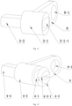
- the third link plate 10 includes a main plate 10-1 provided with a first reinforcing rib 10-1-1 thereon.
- first reinforcing ribs 10-1-1 are arranged on each of a left side face and a right side face of the main plate 10-1, and the first reinforcing rib 10-1-1 and the third link plate 10 are formed integrally.
- the first reinforcing ribs 10-1-1 may be arranged horizontally, vertically, or obliquely, and also may be arranged to cross each other, so as to increase the strength of the main plate 10-1. Further, it should be noted to avoid the first reinforcing rib 10-1-1 from affecting the action or assembling of the first transmission shaft 3, the second transmission shaft 4, the first link plate 8, the second link plate 9, and the third link plate 10.
- the above technical solution has following beneficial effects.
- the strength of the third link plate 10 is strengthened, and the third link plate 10 tends not to deform, so as to ensure the stability of the hinging of the two ends of the third link plate 10 with the first link plate 8 and the second link plate 9, such that it is ensured that the motor 1 transfers the power to the second transmission shaft 4 through the first transmission shaft 3, the first link plate 8, the third link plate 10 and the second link plate 9, and thus the first transmission shaft 3 and the second transmission shaft 4 drive the two air deflectors 11 of the air conditioner to rotate, respectively, thus better adjusting the air blowing direction of the air outlet 13 of the air conditioner.
- a second round hole 8-1 is formed in the end of the first link plate 8 away from the first transmission shaft 3
- a third round hole 9-1 is formed in the end of the second link plate 9 away from the second transmission shaft 4
- one end of the main plate 10-1 is provided with a first boss 10-2 corresponding to the second round hole 8-1
- the other end of the main plate 10-1 is provided with a second boss 10-3 corresponding to the third round hole 9-1.
- An end face of the first boss 10-2 away from the main plate 10-1 is fixedly connected with a second tapered head 10-2-1, a second U-shaped groove 10-2-1-1 is formed in the second tapered head 10-2-1, an end face of the second boss 10-3 away from the main plate 10-1 is fixedly connected with a third tapered head 10-3-1, and a third U-shaped groove 10-3-1 is formed in the third tapered head 10-3-1.
- One end of the main plate 10-1 is provided with the first boss 10-2 corresponding to the second round hole 8-1, that is, a diameter and a hole depth of the second round hole 8-1 correspond to a diameter and a length of the first boss 10-2, respectively, and the first boss 10-2 is fitted in the second round hole 8-1 with a clearance.
- the first boss 10-2 may rotate in the second round hole 8-1, and also, the second round hole 8-1 limits the degree of freedom of the first boss moving forward and back as well as up and down.
- first boss 10-2 and the second tapered head 10-2-1 are coaxially arranged, and a sectional diameter of the second tapered head 10-2-1 adjacent to the main plate 10-1 is greater than a diameter of the first boss 10-2.
- the main plate 10-1 has a limitation to the first boss 10-2, and thus the degree of freedom of the first boss 10-2 translating left and right is limited, such that the first boss 10-2 may only rotate freely in the second round hole 8-1, thereby completing the hinging of the first link plate 8 and the third link plate 10.
- a sectional diameter of the second tapered head 10-2-1 away from the main plate 10-1 is smaller than the diameter of the first boss 10-2, the second U-shaped groove 10-2-1-1 is formed in the second tapered head 10-2-1, an opening of the second U-shaped groove 10-2-1-1 faces towards a side away from the main plate 10-1, a bottom of the second U-shaped groove 10-2-1-1 extends to an end of the first boss 10-2 adjacent to the second tapered head 10-2-1, and the second tapered head 10-2-1 deforms to have a smaller diameter while the second tapered head 10-2-1 is extending into or out of the second round hole 8-1, so as to facilitate the assembling and disassembling of the first link plate 8 and the third link plate 10.
- the other end of the main plate 10-1 is provided with the second boss 10-3 corresponding to the third round hole 9-1, that is, a diameter and a hole depth of the third round hole 9-1 correspond to a diameter and a length of the second boss 10-3, respectively, and the second boss 10-3 is fitted in the third round hole 9-1 with a clearance.
- the second boss 10-3 may rotate in the third round hole 9-1, and also, the third round hole 9-1 limits the degree of freedom of the second boss 10-3 moving forward and back as well as up and down.
- the second boss 10-3 and the third tapered head 10-3-1 are coaxially arranged, and a sectional diameter of the third tapered head 10-3-1 adjacent to the main plate 10-1 is greater than a diameter of the second boss 10-3.
- the main plate 10-1 has a limitation to the second boss 10-3, and thus the degree of freedom of the second boss 10-3 translating left and right is limited, such that the second boss 10-3 may only rotate freely in the third round hole 9-1, thus completing the hinging of the second link plate 9 and the third link plate 10.
- a sectional diameter of the third tapered head 10-3-1 away from the main plate 10-1 is smaller than a diameter of the second boss 10-3
- the third U-shaped groove 10-3-1-1 is formed in the third tapered head 10-3-1
- an opening of the third U-shaped groove 10-3-1-1 faces towards a side away from the main plate 10-1
- a bottom of the third U-shaped groove 10-3-1-1 extends to an end of the second boss 10-3 adjacent to the third tapered head 10-3-1
- the third tapered head 10-3-1 deforms to have a smaller diameter while the third tapered head 10-3-1 is extending into or out of the third round hole 9-1, so as to facilitate the assembling and disassembling of the second link plate 9 and the third link plate 10.
- the above technical solution has following beneficial effects.
- the first transmission shaft 3 drives the first link plate 8 to rotate, the first link plate 8 drives the second link plate 9 to rotate through the third link plate 10, and the second link plate 9 drives the second transmission shaft 4 to rotate, such that the first transmission shaft 3 may effectively transfer the power to the second transmission shaft 4, and the third link plate 10, the first link plate 8 and the second link plate 9 are easy to disassemble and assemble.
- the motor 1 includes a motor main body 1-1 and an output shaft 1-2, the output shaft 1-2 is connected with the motor main body 1-1, the motor main body 1-1 is fixedly connected with the fixing plate 2, the output shaft 1-2 is fixedly connected with the first transmission shaft 3, and the fixing plate 2 is provided with a fourth round hole 2-2 corresponding to the output shaft 1-2.
- the motor main body 1-1 cannot pass through the fourth round hole 2-2, and may be firmly fixed with the fixing plate 2 by means of a threaded connection, adhering or the like.
- the fixing plate 2 may be provided with a hole through which a screw passes, and the motor main body 1-1 is provided with a threaded hole corresponding to the hole through which the screw passes, so as to achieve a threaded connection.
- the motor main body 1-1 may be connected with a plurality of wires (not illustrated in the drawings), and the plurality of wires are configured to be connected with a power supply device (not illustrated in the drawings) and a control device (not illustrated in the drawings) of the air conditioner.
- a diameter of the fourth round hole 2-2 is greater than that of the output shaft 1-2, and a cross-section of an end of the output shaft 1-2 away from the motor main body 1-1 may have a shape of an indented circle, a triangle or a polygon.
- the indented circle refers to a circle whose one or more portions are removed.
- the above technical solution has following beneficial effects.
- the motor main body 1-1 is firmly fixed with the fixing plate 2 to ensure that the output shaft 1-2 and the fourth round hole 2-2 are in a coaxial position. Further, the diameter of the fourth round hole 2-2 is greater than that of the output shaft 1-2, such that the fourth round hole 2-2 will not be scratched during the rotation of the output shaft 1-2, and the motor main body 1-1 drives the output shaft 1-2 to rotate, so as to stably output the power.
- the plurality of wires connected with the motor main body 1-1 are connected with the power supply device and the control device of the air conditioner, so as to control the start and stop of the motor 1, and further to control a rotation angle of the air deflector 11 of the air conditioner, thus better adjusting the air blowing direction of the air outlet 13 of the air conditioner.
- the cross-section of the end of the output shaft 1-2 away from the motor main body 1-1 may have a shape of an indented circle, a triangle or a polygon, so as to better transfer the power of the motor 1 to the first transmission shaft 3.
- the first transmission shaft 3 includes a second shaft body 3-1, and a center portion of one end face of the second shaft body 3-1 adjacent to the fixing plate 2 is provided with an aperture 3-1-1 corresponding to the output shaft 1-2, and the other end face of the second shaft body 3-1 is fixedly connected with a second connecting portion 3-2.
- the aperture 3-1-1 corresponds to the output shaft 1-2, that is, the two are coaxially arranged. Further, when a section of an end of the output shaft 1-2 away from the motor main body 1-1 has a shape of an indented circle, a triangle or a polygon, a section of the aperture 3-1-1 is correspondingly arranged to have a shape of the indented circle, the triangle or the polygon, so as to facilitate that the second shaft body 3-1 and the output shaft 1-2 are fixedly connected through the interference fit and the gluing, such that the degree of freedom of the second shaft body 3-1 moving relative to the output shaft 1-2 is limited.
- the output shaft 1-2 may drive the second shaft body 3-1 to rotate freely.
- the first gear 5 or the first link plate 8 is arranged to the second shaft body 3-1 and is spaced from the fixing plate 2 by a clearance, so as not to affect the rotation of the first gear 5 or the first link plate 8.
- the second connecting portion 3-2 and the second shaft body 3-1 are coaxially arranged, the second connecting portion 3-2 is configured to be fixedly connected with the one of the two air deflectors 11 of the air conditioner, so as to drive this air deflector 11 of the air conditioner to rotate.
- the output shaft 1-2 drives the first transmission shaft 3 to rotate, the first transmission shaft 3 drives the one of the two air deflectors 11 of the air conditioner to rotate through the second connecting portion 3-2, so as to further adjust the air blowing direction of the air outlet 13 of the air conditioner through this air deflector 11 of the air conditioner.
- a fifth round hole 2-3 is arranged above the fourth round hole 2-2, and the fifth round hole 2-3 is formed in the fixing plate 2.
- the second transmission shaft 4 is provided with a third connecting portion 4-1 corresponding to the fifth round hole 2-3, one end face of the third connecting portion 4-1 away from the motor 1 is fixedly connected with a third shaft body 4-2, and the other end face thereof is fixedly connected with a fourth tapered head 4-3.
- a fourth U-shaped groove 4-3-1 is formed in the fourth tapered head 4-3, and an end face of the third shaft body 4-2 away from the third connecting portion 4-1 is fixedly connected with a fourth connecting portion 4-4.
- the working principle of the above technical solution is described as follows.
- the fifth round hole 2-3 is arranged above the fourth round hole 2-2, the second transmission shaft 4 is provided with the third connecting portion 4-1 corresponding to the fifth round hole 2-3, that is, a diameter and a hole depth of the fifth round hole 2-3 correspond to a diameter and a length of the third connecting portion 4-1, respectively, and the third connecting portion 4-1 is fitted in the fifth round hole 2-3 with a clearance.
- the third connecting portion 4-1 may rotate in the fifth round hole 2-3, and also, the fifth round hole 2-3 limits the degree of freedom of the third connecting portion 4-1 moving forward and back as well as up and down.
- the third connecting portion 4-1, the third shaft body 4-2, the fourth tapered head 4-3 and the fourth connecting portion 4-4 are coaxially arranged.
- a diameter of the third shaft body 4-2 is greater than that of the third connecting portion 4-1, and a sectional diameter of the fourth tapered head 4-3 adjacent to the fixing plate 2 is greater than a diameter of the third connecting portion 4-1, such that the degree of freedom of the third connecting portion 4-1 translating left and right is limited.
- the degree of freedom of the third connecting portion 4-1 moving forward and back as well as up and down is limited by the fifth round hole 2-3, and thus the third connecting portion 4-1 may only rotate freely in the fifth round hole 2-3.
- a sectional diameter of the fourth tapered head 4-3 away from the fixing plate 2 is smaller than the diameter of the third connecting portion 4-1
- the fourth U-shaped groove 4-3-1 is formed in the fourth tapered head 4-3
- an opening of the fourth U-shaped groove 4-3-1 faces towards a side away from the fixing plate 2
- a bottom of the fourth U-shaped groove 4-3-1 extends to an end of the third connecting portion 4-1 adjacent to the fourth tapered head 4-3
- the fourth tapered head 4-3 deforms to have a smaller diameter while extending into or out of the fifth round hole 2-3, so as to facilitate the assembling and disassembling of the second transmission shaft 4 and the fixing plate 2.
- the fourth connecting portion 4-4 is configured to be fixedly connected with the other one of the two air deflectors 11 of the air conditioner, so as to drive this air deflector 11 of the air conditioner to rotate.
- the second gear 6 or the second link plate 9 is arranged to the third shaft body 4-2, and is spaced from the fixing plate 2 by a clearance, so as not to affect the rotation of the second gear 6 or the second link plate 9.
- the first transmission shaft 3 drives the second transmission shaft 4 to rotate through the linkage mechanism
- the second transmission shaft 4 drives the other one of the two air deflectors 11 of the air conditioner to rotate through the fourth connecting portion 4-4, so as to further adjust the air blowing direction of the air outlet 13 of the air conditioner through this air deflector 11 of the air conditioner.
- the fixing plate 2 is provided with a second reinforcing rib 2-4.
- the second reinforcing ribs 2-4 are arranged on each of a left side and a right side of the fixing plate 2, and the second reinforcing rib 2-4 and the fixing plate 2 are formed integrally.
- the second reinforcing ribs 2-4 may be arranged horizontally, vertically, or obliquely, and also may be arranged to cross each other, so as to strengthen the strength of the fixing plate 2.
- the above technical solution has following beneficial effects.
- the strength of the fixing plate 2 is increased, and the fixing plate 2 tends not to deform, so as to ensure the stability of the connection of the first transmission shaft 3, the second transmission shaft 4, the gear shaft 7 with the fixing plate 2, such that it is ensured that the motor 1 transfers the power to the second transmission shaft 4 through the first transmission shaft 3 and the linkage mechanism, and thus the first transmission shaft 3 and the second transmission shaft 4 drive the two air deflectors 11 of the air conditioner to rotate, respectively, thus better adjusting the air blowing direction of the air outlet 13 of the air conditioner.
- An air conditioner includes the above driving device for the air deflector of the air condi ti oner.
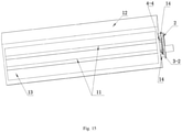
- the air deflector 11 of the air conditioner is arranged to a shell 12 of an indoor unit of the air conditioner, the indoor unit of the air conditioner is provided with an air outlet 13, one end of each of the two air deflectors 11 of the air conditioner is rotatably connected to a left side wall of the air outlet 13, the driving device for the air deflector of the air conditioner of the present disclosure is connected to a right side wall of the air outlet 13, a cushion block 14 is arranged between the fixing plate 2 and the right side wall to keep a clearance therebetween, and the side walls of the air outlet 13 do not affect the power output of the driving device for the air deflector of the air conditioner of the present disclosure.
- Two round holes are formed in the right side wall, diameters of the two round holes are greater than the diameters of the second connecting portion 3-2 and the fourth connecting portion 4-4, the second connecting portion 3-2 and the fourth connecting portion 4-4 are respectively connected with the other ends of the two air deflectors 11 of the air conditioner after passing through the two round holes, and thus the first transmission shaft 3 and the second transmission shaft 4 drive the two air deflectors 11 of the air conditioner to rotate.
- the present disclosure drives the first transmission shaft 3 to rotate through the one motor 1, and drives the second transmission shaft 4 to rotate through the linkage mechanism, so as to drive the two air deflectors 11 of the air conditioner respectively connected with the first transmission shaft 3 and the second transmission shaft 4 to rotate, thus more effectively adjusting the air blowing direction of the air outlet 13 of the air conditioner, such that the present disclosure has the advantages of a low cost, a low power consumption, a contribution to environmental protection, a simple structure and a reliable power transmission.
Landscapes
- Engineering & Computer Science (AREA)
- Chemical & Material Sciences (AREA)
- Combustion & Propulsion (AREA)
- Mechanical Engineering (AREA)
- General Engineering & Computer Science (AREA)
- Air-Flow Control Members (AREA)
Abstract
Description
- The present disclosure relates to the technical field of an air conditioner, and more particularly, to a driving device for an air deflector of an air conditioner and an air conditioner.
- At present, an air outlet of an air conditioner on the market is provided with an air deflector of the air conditioner. When the air conditioner is not working, the air deflector of the air conditioner will seal the air outlet, thus effectively preventing dust and water vapor from entering the air conditioner and also ensuring an aesthetic appearance of the air conditioner. When the air conditioner is in a working state, the air deflector of the air conditioner may adjust an air direction to avoid a direct blowing. That is, the air deflector of the air conditioner may change an air blowing direction to avoid blowing directly to a human body, so as to reduce adverse effects on a human health due to the direct blowing.
- The air deflector of the existing air outlet of the air conditioner mounted on a wall is mostly an integral structure, and is driven by a motor to rotate and change the air blowing direction, which however has a limited effect on a degree of a change in the air direction. Therefore, the whole air deflector of the air conditioner is divided into two separate air deflectors, and the two air deflectors rotate simultaneously, which may better change the air blowing direction of the air outlet of the air conditioner. However, if two motors are selected to drive the two air deflectors, respectively, the cost and the power consumption are relatively high, which is not conducive to the protection of environment. Thus, it is necessary to propose a driving device for an air deflector of an air conditioner and an air conditioner, so as to at least partially solve the problems existing in the prior art.
- Concepts of a serial of simplified forms are introduced in the summary of the present disclosure, which will be further explained in the specific embodiments. The summary of the present disclosure does not mean to try to define the key features and the necessary technical features of the claimed technical solution, nor does it mean to try to determine the protection scope of the claimed technical solution.
- In order to at least partially solve the above problems, the present disclosure provides according to a first aspect a driving device for an air deflector of an air conditioner, including: a motor, a fixing plate, a first transmission shaft and a second transmission shaft. The motor is connected with a side of the fixing plate, the first transmission shaft and the second transmission shaft are arranged at a side of the fixing plate away from the motor, and the second transmission shaft is arranged above the first transmission shaft. The first transmission shaft is fixedly connected with the motor, the second transmission shaft is rotatably connected with the fixing plate, and the first transmission shaft is connected with the second transmission shaft through a linkage mechanism.
- Preferably, the linkage mechanism includes a first gear, a second gear and a gear shaft, the first gear and the first transmission shaft are arranged coaxially, the second gear and the second transmission shaft are arranged coaxially, the gear shaft is arranged between the first gear and the second gear, the gear shaft is rotatably connected with the fixing plate, a third gear is arranged to the gear shaft, and the first gear and the second gear are meshed and connected with the third gear, respectively.
- Preferably, an end face of the third gear adjacent to the fixing plate is fixedly connected with a first shaft body, an end face of the first shaft body away from the third gear is fixedly connected with a first connecting portion, the fixing plate is provided with a first round hole corresponding to the first connecting portion, an end face of the first connecting portion away from the first shaft body is fixedly connected with a first tapered head, and a first U-shaped groove is formed in the first tapered head.
- Preferably, the linkage mechanism includes a first link plate, a second link plate and a third link plate, the first link plate is arranged to the first transmission shaft, the second link plate is arranged to the second transmission shaft, the third link plate is arranged between the first link plate and the second link plate, one end of the third link plate is hinged with an end of the first link plate away from the first transmission shaft, and the other end thereof is hinged with an end of the second link plate away from the second transmission shaft.
- Preferably, the third link plate includes a main plate provided with a first reinforcing rib thereon.
- Preferably, a second round hole is formed in the end of the first link plate away from the first transmission shaft, a third round hole is formed in the end of the second link plate away from the second transmission shaft, one end of the main plate is provided with a first boss corresponding to the second round hole, the other end of the main plate is provided with a second boss corresponding to the third round hole, an end face of the first boss away from the main plate is fixedly connected with a second tapered head, a second U-shaped groove is formed in the second tapered head, an end face of the second boss away from the main plate is fixedly connected with a third tapered head, and a third U-shaped groove is formed in the third tapered head.
- Preferably, the motor includes a motor main body and an output shaft, the output shaft is connected with the motor main body, the motor main body is fixedly connected with the fixing plate, the output shaft is fixedly connected with the first transmission shaft, and the fixing plate is provided with a fourth round hole corresponding to the output shaft.
- Preferably, the first transmission shaft includes a second shaft body, and a center portion of one end face of the second shaft body adjacent to the fixing plate is provided with an aperture corresponding to the output shaft, and the other end face of the second shaft body is fixedly connected with a second connecting portion.
- Preferably, a fifth round hole is arranged above the fourth round hole, the fifth round hole is formed in the fixing plate, the second transmission shaft is provided with a third connecting portion corresponding to the fifth round hole, one end face of the third connecting portion away from the motor is fixedly connected with a third shaft body, the other end face thereof is fixedly connected with a fourth tapered head, a fourth U-shaped groove is formed in the fourth tapered head, and an end face of the third shaft body away from the third connecting portion is fixedly connected with a fourth connecting portion.
- Preferably, the fixing plate is provided with a second reinforcing rib thereon.
- The present disclosure provides according to a second aspect an air conditioner, including the driving device according to the first aspect of the present disclosure for the air deflector of the air conditioner.
- Compared to the prior art, the present disclosure at least includes following significant effects.
- The present disclosure drives the first transmission shaft and the second transmission shaft to rotate through the one motor, and thus drives two air deflectors of the air conditioner respectively connected with the first transmission shaft and the second transmission shaft to rotate, so as to more effectively adjust the air blowing direction of the air outlet of the air conditioner, such that the present disclosure has the advantages of a low cost, a low power consumption, a contribution to environmental protection, a simple structure and a reliable power transmission.
- Other advantages, objectives and features of the driving device for the air deflector of the air conditioner and the air conditioner described in the present disclosure will be partially reflected by the following descriptions, and also will be understood by those skilled in the related art according to the research and practice of the present disclosure.
- The accompanying drawings provide a further understanding of the present disclosure and constitute as part of the present disclosure. The accompanying drawings are used to explain the present disclosure with the embodiments of the present disclosure, which do not constitute as a limitation of the present disclosure.
-
Fig. 1 is a schematic view of a first kind of a connection structure of a first transmission shaft and a second transmission shaft in a driving device for an air deflector of an air conditioner according to the present disclosure. -
Fig. 2 is a left view ofFig. 1 . -
Fig. 3 is a right view ofFig. 1 . -
Fig. 4 is a schematic view of a gear shaft inFig. 1 . -
Fig. 5 is a schematic view of an assembly of a first gear and a first transmission shaft inFig. 1 . -
Fig. 6 is a schematic view of an assembly of a second gear and a second transmission shaft inFig. 1 . -
Fig. 7 is a schematic view of a second kind of a connection structure of a first transmission shaft and a second transmission shaft in a driving device for an air deflector of an air conditioner according to the present disclosure. -
Fig. 8 is a left view ofFig. 7 . -
Fig. 9 is a right view ofFig. 7 . -
Fig. 10 is a schematic view of a third link plate inFig. 7 . -
Fig. 11 is a schematic view of an assembly of a first link plate and a first transmission shaft inFig. 7 . -
Fig. 12 is a schematic view of an assembly of a second link plate and a second transmission shaft inFig. 7 . -
Fig. 13 is a schematic view of a motor of a driving device for an air deflector of an air conditioner. -
Fig. 14 is a schematic view of a fixing plate of a driving device for an air deflector of an air conditioner. -
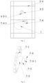
Fig. 15 is a schematic view of mounting and use of a driving device for an air deflector of an air conditioner. - The present disclosure is further described detailed below in combination with the accompanying drawings and embodiments, such that those skilled in the related art can implement the present disclosure with reference to the literal content of the description.
- It should be understood that terms such as "having," "including," and "comprising" as used herein do not exclude an existence or addition of one or more other elements or combinations thereof.
- As illustrated in
Figs. 1- 15 , the present disclosure provides a driving device for an air deflector of an air conditioner, which includes amotor 1, afixing plate 2, afirst transmission shaft 3 and asecond transmission shaft 4. Themotor 1 is connected to a side of thefixing plate 2, thefirst transmission shaft 3 and thesecond transmission shaft 4 are arranged to another side of thefixing plate 2 away from themotor 1, and thesecond transmission shaft 4 is arranged above thefirst transmission shaft 3. Thefirst transmission shaft 3 is fixedly connected with themotor 1, thesecond transmission shaft 4 is rotatably connected with thefixing plate 2, and thefirst transmission shaft 3 is connected with thesecond transmission shaft 4 through a linkage mechanism. - The working principle of the above technical solution is described as follows. The
motor 1 drives thefirst transmission shaft 3 to rotate, thefirst transmission shaft 3 drives thesecond transmission shaft 4 to rotate through the linkage mechanism, an end of thefirst transmission shaft 3 away from thefixing plate 2 is connected with one of twoair deflectors 11 of the air conditioner, and drives thisair deflector 11 of the air conditioner to rotate, and an end of thesecond transmission shaft 4 away from thefixing plate 2 is connected with the other one of the twoair deflectors 11 of the air conditioner, and drives thisair deflector 11 of the air conditioner to rotate. - The above technical solution has following beneficial effects. The present disclosure drives the
first transmission shaft 3 to rotate through the onemotor 1, and drives thesecond transmission shaft 4 to rotate through the linkage mechanism, so as to drive the twoair deflectors 11 of the air conditioner respectively connected with thefirst transmission shaft 3 and thesecond transmission shaft 4 to rotate, thus more effectively adjusting an air blowing direction of anair outlet 13 of the air conditioner, such that the present disclosure has the advantages of a low cost, a low power consumption, a contribution to environmental protection, a simple structure and a reliable power transmission. -
Figs. 1-6 and13-14 illustrate a first technical solution for the connection of the first transmission shaft and the second transmission shaft. - In an embodiment, the linkage mechanism includes a first gear 5, a
second gear 6 and agear shaft 7, the first gear 5 and thefirst transmission shaft 3 are arranged coaxially, thesecond gear 6 and thesecond transmission shaft 4 are arranged coaxially, thegear shaft 7 is arranged between the first gear 5 and thesecond gear 6, thegear shaft 7 is rotatably connected with thefixing plate 2, a third gear 7-1 is arranged on thegear shaft 7, and the first gear 5 and thesecond gear 6 are meshed and connected with the third gear 7-1, respectively. - The working principle of the above technical solution is described as follows. The first gear 5, the
second gear 6, and the third gear 7-1 have the same thickness and are spaced from thefixing plate 2 by the same clearance. Thefirst transmission shaft 3 drives the first gear 5 to rotate, the first gear 5 is meshed with the third gear 7-1, and thus the first gear 5 drives thegear shaft 7 to rotate. Thesecond gear 6 is meshed with the third gear 7-1, and thus thesecond gear 6 is driven to rotate. Thesecond gear 6 drives thesecond transmission shaft 4 to rotate. The first gear 5, thesecond gear 6 and thegear shaft 7 may be arranged on a straight line or in a triangle according to actual needs. - The above technical solution has following beneficial effects. The
first transmission shaft 3 effectively drives thesecond transmission shaft 4 to rotate through the first gear 5, thesecond gear 6 and thegear shaft 7. - In an embodiment, an end face of the third gear 7-1 adjacent to the fixing
plate 2 is fixedly connected with a first shaft body 7-2, an end face of the first shaft body 7-2 away from the third gear 7-1 is fixedly connected with a first connecting portion 7-3, the fixingplate 2 is provided with a first round hole 2-1 corresponding to the first connecting portion 7-3, an end face of the first connecting portion 7-3 away from the first shaft body 7-2 is fixedly connected with a first tapered head 7-4, and a first U-shaped groove 7-4-1 is formed in the first tapered head 7-4. - The working principle of the above technical solution is described as follows. The fixing
plate 2 is provided with the first round hole 2-1 corresponding to the first connecting portion 7-3, that is, a diameter and a hole depth of the first round hole 2-1 correspond to a diameter and a length of the first connecting portion 7-3, respectively, and the first connecting portion 7-3 is fitted in the first round hole 2-1 with a clearance, such that the first connecting portion 7-3 may rotate in the first round hole 2-1. Also, the first round hole 2-1 limits the degree of freedom of the first connecting portion 7-3 moving forward and back as well as up and down. Further, the third gear 7-1, the first shaft body 7-2, the first connecting portion 7-3 and the first tapered head 7-4 are coaxially arranged, a diameter of the first shaft body 7-2 is greater than that of the first connecting portion 7-3, and a sectional diameter of the first tapered head 7-4 adjacent to the fixingplate 2 is greater than the diameter of the first connecting portion 7-3. The degree of freedom of the first connecting portion 7-3 translating left and right is limited, and the degree of freedom of the first connecting portion 7-3 moving forward and back as well as up and down is also limited by the first round hole 2-1, such that the first connecting portion 7-3 may only rotate freely in the first round hole 2-1. Additionally, a sectional diameter of the first tapered head 7-4 away from the fixingplate 2 is smaller than the diameter of the first connecting portion 7-3, a first U-shaped groove 7-4-1 is formed the first tapered head 7-4, an opening of the first U-shaped groove 7-4-1 faces towards a side away from the fixingplate 2, a bottom of the first U-shaped groove 7-4-1 extends to an end of the first connecting portion 7-3 adjacent to the first tapered head 7-4, and the first tapered head 7-4 deforms to have a smaller diameter while the first tapered head 7-4 is extending into or out of the first round hole 2-1, so as to facilitate the assembling and disassembling of thegear shaft 7 and the fixingplate 2. - The above technical solution has following beneficial effects. The
gear shaft 7 rotates freely in the first round hole 2-1 of the fixingplate 2 along its axial direction, thefirst transmission shaft 3 drives the first gear 5 to rotate, the first gear 5 drives thegear shaft 7 to rotate through the third gear 7-1, thegear shaft 7 drives thesecond gear 6 to rotate through the third gear 7-1, and thesecond gear 6 drives thesecond transmission shaft 4 to rotate, such that thefirst transmission shaft 3 effectively transfers the power to thesecond transmission shaft 4, and thegear shaft 7 and the fixingplate 2 are easy to disassemble and assemble. -
Figs. 7-14 illustrate a second technical solution for the connection of thefirst transmission shaft 3 and thesecond transmission shaft 4. - In an embodiment, the linkage mechanism includes a
first link plate 8, asecond link plate 9 and athird link plate 10, thefirst link plate 8 is arranged to thefirst transmission shaft 3, thesecond link plate 9 is arranged to thesecond transmission shaft 4, and thethird link plate 10 is arranged between thefirst link plate 8 and thesecond link plate 9. One end of thethird link plate 10 is hinged with an end of thefirst link plate 8 away from thefirst transmission shaft 3, and the other end thereof is hinged with an end of thesecond link plate 9 away from thesecond transmission shaft 4. - The working principle of the above technical solution is described as follows. The
first link plate 8 and thesecond link plate 9 have the same thickness and are spaced from the fixingplate 2 by the same clearance. Thefirst transmission shaft 3 drives thefirst link plate 8 to rotate. One end of thethird link plate 10 is hinged with the end of thefirst link plate 8 away from thefirst transmission shaft 3, and the other end thereof is hinged with the end of thesecond link plate 9 away from thesecond transmission shaft 4, such that thefirst link plate 8 drives thesecond link plate 9 to rotate through thethird link plate 10, and thesecond link plate 9 drives thesecond transmission shaft 4 to rotate. - The above technical solution has following beneficial effects. The
first transmission shaft 3 effectively drives thesecond transmission shaft 4 to rotate through thefirst link plate 8, thethird link plate 10 and thesecond link plate 9. - In an embodiment, the
third link plate 10 includes a main plate 10-1 provided with a first reinforcing rib 10-1-1 thereon. - The working principle of the above technical solution is described as follows. One or a plurality of the first reinforcing ribs 10-1-1 are arranged on each of a left side face and a right side face of the main plate 10-1, and the first reinforcing rib 10-1-1 and the
third link plate 10 are formed integrally. When a plurality of the first reinforcing ribs 10-1-1 are provided, the first reinforcing ribs 10-1-1 may be arranged horizontally, vertically, or obliquely, and also may be arranged to cross each other, so as to increase the strength of the main plate 10-1. Further, it should be noted to avoid the first reinforcing rib 10-1-1 from affecting the action or assembling of thefirst transmission shaft 3, thesecond transmission shaft 4, thefirst link plate 8, thesecond link plate 9, and thethird link plate 10. - The above technical solution has following beneficial effects. The strength of the
third link plate 10 is strengthened, and thethird link plate 10 tends not to deform, so as to ensure the stability of the hinging of the two ends of thethird link plate 10 with thefirst link plate 8 and thesecond link plate 9, such that it is ensured that themotor 1 transfers the power to thesecond transmission shaft 4 through thefirst transmission shaft 3, thefirst link plate 8, thethird link plate 10 and thesecond link plate 9, and thus thefirst transmission shaft 3 and thesecond transmission shaft 4 drive the twoair deflectors 11 of the air conditioner to rotate, respectively, thus better adjusting the air blowing direction of theair outlet 13 of the air conditioner. - In an embodiment, a second round hole 8-1 is formed in the end of the
first link plate 8 away from thefirst transmission shaft 3, a third round hole 9-1 is formed in the end of thesecond link plate 9 away from thesecond transmission shaft 4, one end of the main plate 10-1 is provided with a first boss 10-2 corresponding to the second round hole 8-1, and the other end of the main plate 10-1 is provided with a second boss 10-3 corresponding to the third round hole 9-1. An end face of the first boss 10-2 away from the main plate 10-1 is fixedly connected with a second tapered head 10-2-1, a second U-shaped groove 10-2-1-1 is formed in the second tapered head 10-2-1, an end face of the second boss 10-3 away from the main plate 10-1 is fixedly connected with a third tapered head 10-3-1, and a third U-shaped groove 10-3-1 is formed in the third tapered head 10-3-1. - The working principle of the above technical solution is described as follows. One end of the main plate 10-1 is provided with the first boss 10-2 corresponding to the second round hole 8-1, that is, a diameter and a hole depth of the second round hole 8-1 correspond to a diameter and a length of the first boss 10-2, respectively, and the first boss 10-2 is fitted in the second round hole 8-1 with a clearance. The first boss 10-2 may rotate in the second round hole 8-1, and also, the second round hole 8-1 limits the degree of freedom of the first boss moving forward and back as well as up and down. Further, the first boss 10-2 and the second tapered head 10-2-1 are coaxially arranged, and a sectional diameter of the second tapered head 10-2-1 adjacent to the main plate 10-1 is greater than a diameter of the first boss 10-2. In addition, the main plate 10-1 has a limitation to the first boss 10-2, and thus the degree of freedom of the first boss 10-2 translating left and right is limited, such that the first boss 10-2 may only rotate freely in the second round hole 8-1, thereby completing the hinging of the
first link plate 8 and thethird link plate 10. Further, a sectional diameter of the second tapered head 10-2-1 away from the main plate 10-1 is smaller than the diameter of the first boss 10-2, the second U-shaped groove 10-2-1-1 is formed in the second tapered head 10-2-1, an opening of the second U-shaped groove 10-2-1-1 faces towards a side away from the main plate 10-1, a bottom of the second U-shaped groove 10-2-1-1 extends to an end of the first boss 10-2 adjacent to the second tapered head 10-2-1, and the second tapered head 10-2-1 deforms to have a smaller diameter while the second tapered head 10-2-1 is extending into or out of the second round hole 8-1, so as to facilitate the assembling and disassembling of thefirst link plate 8 and thethird link plate 10. - The other end of the main plate 10-1 is provided with the second boss 10-3 corresponding to the third round hole 9-1, that is, a diameter and a hole depth of the third round hole 9-1 correspond to a diameter and a length of the second boss 10-3, respectively, and the second boss 10-3 is fitted in the third round hole 9-1 with a clearance. The second boss 10-3 may rotate in the third round hole 9-1, and also, the third round hole 9-1 limits the degree of freedom of the second boss 10-3 moving forward and back as well as up and down. Further, the second boss 10-3 and the third tapered head 10-3-1 are coaxially arranged, and a sectional diameter of the third tapered head 10-3-1 adjacent to the main plate 10-1 is greater than a diameter of the second boss 10-3. In addition, the main plate 10-1 has a limitation to the second boss 10-3, and thus the degree of freedom of the second boss 10-3 translating left and right is limited, such that the second boss 10-3 may only rotate freely in the third round hole 9-1, thus completing the hinging of the
second link plate 9 and thethird link plate 10. Further, a sectional diameter of the third tapered head 10-3-1 away from the main plate 10-1 is smaller than a diameter of the second boss 10-3, the third U-shaped groove 10-3-1-1 is formed in the third tapered head 10-3-1, an opening of the third U-shaped groove 10-3-1-1 faces towards a side away from the main plate 10-1, a bottom of the third U-shaped groove 10-3-1-1 extends to an end of the second boss 10-3 adjacent to the third tapered head 10-3-1, and the third tapered head 10-3-1 deforms to have a smaller diameter while the third tapered head 10-3-1 is extending into or out of the third round hole 9-1, so as to facilitate the assembling and disassembling of thesecond link plate 9 and thethird link plate 10. - The above technical solution has following beneficial effects. The
first transmission shaft 3 drives thefirst link plate 8 to rotate, thefirst link plate 8 drives thesecond link plate 9 to rotate through thethird link plate 10, and thesecond link plate 9 drives thesecond transmission shaft 4 to rotate, such that thefirst transmission shaft 3 may effectively transfer the power to thesecond transmission shaft 4, and thethird link plate 10, thefirst link plate 8 and thesecond link plate 9 are easy to disassemble and assemble. - In an embodiment, the
motor 1 includes a motor main body 1-1 and an output shaft 1-2, the output shaft 1-2 is connected with the motor main body 1-1, the motor main body 1-1 is fixedly connected with the fixingplate 2, the output shaft 1-2 is fixedly connected with thefirst transmission shaft 3, and the fixingplate 2 is provided with a fourth round hole 2-2 corresponding to the output shaft 1-2. - The working principle of the above technical solution is described as follows. The motor main body 1-1 cannot pass through the fourth round hole 2-2, and may be firmly fixed with the fixing
plate 2 by means of a threaded connection, adhering or the like. When the motor main body 1-1 is threadedly connected and fixed with the fixingplate 2, the fixingplate 2 may be provided with a hole through which a screw passes, and the motor main body 1-1 is provided with a threaded hole corresponding to the hole through which the screw passes, so as to achieve a threaded connection. The motor main body 1-1 may be connected with a plurality of wires (not illustrated in the drawings), and the plurality of wires are configured to be connected with a power supply device (not illustrated in the drawings) and a control device (not illustrated in the drawings) of the air conditioner. A diameter of the fourth round hole 2-2 is greater than that of the output shaft 1-2, and a cross-section of an end of the output shaft 1-2 away from the motor main body 1-1 may have a shape of an indented circle, a triangle or a polygon. The indented circle refers to a circle whose one or more portions are removed. - The above technical solution has following beneficial effects. The motor main body 1-1 is firmly fixed with the fixing
plate 2 to ensure that the output shaft 1-2 and the fourth round hole 2-2 are in a coaxial position. Further, the diameter of the fourth round hole 2-2 is greater than that of the output shaft 1-2, such that the fourth round hole 2-2 will not be scratched during the rotation of the output shaft 1-2, and the motor main body 1-1 drives the output shaft 1-2 to rotate, so as to stably output the power. The plurality of wires connected with the motor main body 1-1 are connected with the power supply device and the control device of the air conditioner, so as to control the start and stop of themotor 1, and further to control a rotation angle of theair deflector 11 of the air conditioner, thus better adjusting the air blowing direction of theair outlet 13 of the air conditioner. The cross-section of the end of the output shaft 1-2 away from the motor main body 1-1 may have a shape of an indented circle, a triangle or a polygon, so as to better transfer the power of themotor 1 to thefirst transmission shaft 3. - In an embodiment, the
first transmission shaft 3 includes a second shaft body 3-1, and a center portion of one end face of the second shaft body 3-1 adjacent to the fixingplate 2 is provided with an aperture 3-1-1 corresponding to the output shaft 1-2, and the other end face of the second shaft body 3-1 is fixedly connected with a second connecting portion 3-2. - The working principle of the above technical solution is described as follows. The aperture 3-1-1 corresponds to the output shaft 1-2, that is, the two are coaxially arranged. Further, when a section of an end of the output shaft 1-2 away from the motor main body 1-1 has a shape of an indented circle, a triangle or a polygon, a section of the aperture 3-1-1 is correspondingly arranged to have a shape of the indented circle, the triangle or the polygon, so as to facilitate that the second shaft body 3-1 and the output shaft 1-2 are fixedly connected through the interference fit and the gluing, such that the degree of freedom of the second shaft body 3-1 moving relative to the output shaft 1-2 is limited. Further, there is a clearance between the second shaft body 3-1 and the fixing
plate 2, and thus the output shaft 1-2 may drive the second shaft body 3-1 to rotate freely. The first gear 5 or thefirst link plate 8 is arranged to the second shaft body 3-1 and is spaced from the fixingplate 2 by a clearance, so as not to affect the rotation of the first gear 5 or thefirst link plate 8. The second connecting portion 3-2 and the second shaft body 3-1 are coaxially arranged, the second connecting portion 3-2 is configured to be fixedly connected with the one of the twoair deflectors 11 of the air conditioner, so as to drive thisair deflector 11 of the air conditioner to rotate. - The above technical solution has following beneficial effects. The output shaft 1-2 drives the
first transmission shaft 3 to rotate, thefirst transmission shaft 3 drives the one of the twoair deflectors 11 of the air conditioner to rotate through the second connecting portion 3-2, so as to further adjust the air blowing direction of theair outlet 13 of the air conditioner through thisair deflector 11 of the air conditioner. - In an embodiment, a fifth round hole 2-3 is arranged above the fourth round hole 2-2, and the fifth round hole 2-3 is formed in the fixing
plate 2. Thesecond transmission shaft 4 is provided with a third connecting portion 4-1 corresponding to the fifth round hole 2-3, one end face of the third connecting portion 4-1 away from themotor 1 is fixedly connected with a third shaft body 4-2, and the other end face thereof is fixedly connected with a fourth tapered head 4-3. A fourth U-shaped groove 4-3-1 is formed in the fourth tapered head 4-3, and an end face of the third shaft body 4-2 away from the third connecting portion 4-1 is fixedly connected with a fourth connecting portion 4-4. - The working principle of the above technical solution is described as follows. The fifth round hole 2-3 is arranged above the fourth round hole 2-2, the
second transmission shaft 4 is provided with the third connecting portion 4-1 corresponding to the fifth round hole 2-3, that is, a diameter and a hole depth of the fifth round hole 2-3 correspond to a diameter and a length of the third connecting portion 4-1, respectively, and the third connecting portion 4-1 is fitted in the fifth round hole 2-3 with a clearance. The third connecting portion 4-1 may rotate in the fifth round hole 2-3, and also, the fifth round hole 2-3 limits the degree of freedom of the third connecting portion 4-1 moving forward and back as well as up and down. The third connecting portion 4-1, the third shaft body 4-2, the fourth tapered head 4-3 and the fourth connecting portion 4-4 are coaxially arranged. A diameter of the third shaft body 4-2 is greater than that of the third connecting portion 4-1, and a sectional diameter of the fourth tapered head 4-3 adjacent to the fixingplate 2 is greater than a diameter of the third connecting portion 4-1, such that the degree of freedom of the third connecting portion 4-1 translating left and right is limited. In addition, the degree of freedom of the third connecting portion 4-1 moving forward and back as well as up and down is limited by the fifth round hole 2-3, and thus the third connecting portion 4-1 may only rotate freely in the fifth round hole 2-3. Additionally, a sectional diameter of the fourth tapered head 4-3 away from the fixingplate 2 is smaller than the diameter of the third connecting portion 4-1, the fourth U-shaped groove 4-3-1 is formed in the fourth tapered head 4-3, an opening of the fourth U-shaped groove 4-3-1 faces towards a side away from the fixingplate 2, a bottom of the fourth U-shaped groove 4-3-1 extends to an end of the third connecting portion 4-1 adjacent to the fourth tapered head 4-3, and the fourth tapered head 4-3 deforms to have a smaller diameter while extending into or out of the fifth round hole 2-3, so as to facilitate the assembling and disassembling of thesecond transmission shaft 4 and the fixingplate 2. Furthermore, the fourth connecting portion 4-4 is configured to be fixedly connected with the other one of the twoair deflectors 11 of the air conditioner, so as to drive thisair deflector 11 of the air conditioner to rotate. Thesecond gear 6 or thesecond link plate 9 is arranged to the third shaft body 4-2, and is spaced from the fixingplate 2 by a clearance, so as not to affect the rotation of thesecond gear 6 or thesecond link plate 9. - The above technical solution has following beneficial effects. The
first transmission shaft 3 drives thesecond transmission shaft 4 to rotate through the linkage mechanism, thesecond transmission shaft 4 drives the other one of the twoair deflectors 11 of the air conditioner to rotate through the fourth connecting portion 4-4, so as to further adjust the air blowing direction of theair outlet 13 of the air conditioner through thisair deflector 11 of the air conditioner. - In an embodiment, the fixing
plate 2 is provided with a second reinforcing rib 2-4. - The working principle of the above technical solution is described as follows. One or a plurality of the second reinforcing ribs 2-4 are arranged on each of a left side and a right side of the fixing
plate 2, and the second reinforcing rib 2-4 and the fixingplate 2 are formed integrally. When a plurality of the second reinforcing ribs 2-4 are provided, the second reinforcing ribs 2-4 may be arranged horizontally, vertically, or obliquely, and also may be arranged to cross each other, so as to strengthen the strength of the fixingplate 2. Further, it should be noted to avoid the second reinforcing rib 2-4 from affecting the action or the assembling of themotor 1, thefirst transmission shaft 3, thesecond transmission shaft 4, the first gear 5, thesecond gear 6, thegear shaft 7, thefirst link plate 8, thesecond link plate 9, and thethird link plate 10. - The above technical solution has following beneficial effects. The strength of the fixing
plate 2 is increased, and the fixingplate 2 tends not to deform, so as to ensure the stability of the connection of thefirst transmission shaft 3, thesecond transmission shaft 4, thegear shaft 7 with the fixingplate 2, such that it is ensured that themotor 1 transfers the power to thesecond transmission shaft 4 through thefirst transmission shaft 3 and the linkage mechanism, and thus thefirst transmission shaft 3 and thesecond transmission shaft 4 drive the twoair deflectors 11 of the air conditioner to rotate, respectively, thus better adjusting the air blowing direction of theair outlet 13 of the air conditioner. - An air conditioner includes the above driving device for the air deflector of the air condi ti oner.
- The working principle of the above technical solution is described as follows. The
air deflector 11 of the air conditioner is arranged to ashell 12 of an indoor unit of the air conditioner, the indoor unit of the air conditioner is provided with anair outlet 13, one end of each of the twoair deflectors 11 of the air conditioner is rotatably connected to a left side wall of theair outlet 13, the driving device for the air deflector of the air conditioner of the present disclosure is connected to a right side wall of theair outlet 13, acushion block 14 is arranged between the fixingplate 2 and the right side wall to keep a clearance therebetween, and the side walls of theair outlet 13 do not affect the power output of the driving device for the air deflector of the air conditioner of the present disclosure. Two round holes (not illustrated in the drawings) are formed in the right side wall, diameters of the two round holes are greater than the diameters of the second connecting portion 3-2 and the fourth connecting portion 4-4, the second connecting portion 3-2 and the fourth connecting portion 4-4 are respectively connected with the other ends of the twoair deflectors 11 of the air conditioner after passing through the two round holes, and thus thefirst transmission shaft 3 and thesecond transmission shaft 4 drive the twoair deflectors 11 of the air conditioner to rotate. - The above technical solution has following beneficial effects. The present disclosure drives the
first transmission shaft 3 to rotate through the onemotor 1, and drives thesecond transmission shaft 4 to rotate through the linkage mechanism, so as to drive the twoair deflectors 11 of the air conditioner respectively connected with thefirst transmission shaft 3 and thesecond transmission shaft 4 to rotate, thus more effectively adjusting the air blowing direction of theair outlet 13 of the air conditioner, such that the present disclosure has the advantages of a low cost, a low power consumption, a contribution to environmental protection, a simple structure and a reliable power transmission. - In the description of the present disclosure, it should be understood that, terms such as "central," "longitudinal," "lateral," "length," "width," "thickness," "upper," "lower," "front," "rear," "left," "right," "vertical," "horizontal," "top," "bottom," "inner," "outer," "clockwise", "counter clockwise", "axial," "radial", and "circumferential" indicate an orientation or a position relationship based on an orientation or a position relationship illustrated in the accompanying drawings, which is only for convenience of descriptions or for simplifying descriptions of the present disclosure, and does not indicate or imply that the device or element referred to must have a particular orientation or be constructed and operated in a specific orientation, and hence cannot be construed as limitation to the present disclosure.
- In the present disclosure, it should be noted that, unless specified otherwise, terms "mounted," "coupled," "connected," and "fixed," should be understood broadly, the terms may indicate, for example, fixed connections, detachable connections, or integral connections, may also indicate mechanical or electrical connections or mutual communications, may also indicate direct connections or indirect connections via intermediate mediums, and may also indicate an inner communication of two elements or an interaction between two elements. The specific meanings of the terms in embodiments of the present disclosure may be understood by those skilled in the art according to particular circumstances.
- Although disclosed as above, the implementation solutions of the present disclosure are not limited to the applications listed in the description and the embodiments, and can fully be applied to various fields suitable for the present disclosure. For those familiar with the related art, other modifications can be easily achieved. Therefore, without departing from a general concept defined by claims and an equivalent scope, the present disclosure is not limited to specific details and legends illustrated and described herein.
Claims (11)
- A driving device for an air deflector of an air conditioner, comprising a motor (1), a fixing plate (2), a first transmission shaft (3) and a second transmission shaft (4), the motor (1) being connected with a side of the fixing plate (2), the first transmission shaft (3) and the second transmission shaft (4) being arranged at a side of the fixing plate (2) away from the motor (1), the second transmission shaft (4) being arranged above the first transmission shaft (3), the first transmission shaft (3) being fixedly connected with the motor (1), the second transmission shaft (4) being rotatably connected with the fixing plate (2), and the first transmission shaft (3) being connected with the second transmission shaft (4) through a linkage mechanism.
- The driving device for the air deflector of the air conditioner according to claim 1, wherein the linkage mechanism comprises a first gear (5), a second gear (6) and a gear shaft (7), the first gear (5) and the first transmission shaft (3) are arranged coaxially, the second gear (6) and the second transmission shaft (4) are arranged coaxially, the gear shaft (7) is arranged between the first gear (5) and the second gear (6), the gear shaft (7) is rotatably connected with the fixing plate (2), a third gear (7-1) is arranged to the gear shaft (7), and the first gear (5) and the second gear (6) are meshed and connected with the third gear (7-1), respectively.
- The driving device for the air deflector of the air conditioner according to claim 2, wherein an end face of the third gear (7-1) adjacent to the fixing plate (2) is fixedly connected with a first shaft body (7-2), an end face of the first shaft body (7-2) away from the third gear (7-1) is fixedly connected with a first connecting portion (7-3), the fixing plate (2) is provided with a first round hole (2-1) corresponding to the first connecting portion (7-3), an end face of the first connecting portion (7-3) away from the first shaft body (7-2) is fixedly connected with a first tapered head (7-4), and a first U-shaped groove (7-4-1) is formed in the first tapered head (7-4).
- The driving device for the air deflector of the air conditioner according to claim 1, wherein the linkage mechanism comprises a first link plate (8), a second link plate (9) and a third link plate (10), the first link plate (8) is arranged to the first transmission shaft (3), the second link plate (9) is arranged to the second transmission shaft (4), the third link plate (10) is arranged between the first link plate (8) and the second link plate (9), one end of the third link plate (10) is hinged with an end of the first link plate (8) away from the first transmission shaft (3), and the other end thereof is hinged with an end of the second link plate (9) away from the second transmission shaft (4).
- The driving device for the air deflector of the air conditioner according to claim 4, wherein the third link plate (10) comprises a main plate (10-1) provided with a first reinforcing rib (10-1-1) thereon.
- The driving device for the air deflector of the air conditioner according to claim 5, wherein a second round hole (8-1) is formed in the end of the first link plate (8) away from the first transmission shaft (3), a third round hole (9-1) is formed in the end of the second link plate (9) away from the second transmission shaft (4), one end of the main plate (10-1) is provided with a first boss (10-2) corresponding to the second round hole (8-1), the other end of the main plate (10-1) is provided with a second boss (10-3) corresponding to the third round hole (9-1), an end face of the first boss (10-2) away from the main plate (10-1) is fixedly connected with a second tapered head (10-2-1), a second U-shaped groove (10-2-1-1) is formed in the second tapered head (10-2-1), an end face of the second boss (10-3) away from the main plate (10-1) is fixedly connected with a third tapered head (10-3-1), and the third U-shaped groove (10-3-1-1) is formed in the third tapered head (10-3-1).
- The driving device for the air deflector of the air conditioner according to any one of claims 1 to 6, wherein the motor (1) comprises a motor main body (1-1) and an output shaft (1-2), the output shaft (1-2) is connected with the motor main body (1-1), the motor main body (1-1) is fixedly connected with the fixing plate (2), the output shaft (1-2) is fixedly connected with the first transmission shaft (3), and the fixing plate (2) is provided with a fourth round hole (2-2) corresponding to the output shaft (1-2).
- The driving device for the air deflector of the air conditioner according to claim 7, wherein the first transmission shaft (3) comprises a second shaft body (3-1), and a center portion of one end face of the second shaft body (3-1) adjacent to the fixing plate (2) is provided with an aperture (3-1-1) corresponding to the output shaft (1-2), and the other end face of the second shaft body (3-1) is fixedly connected with a second connecting portion (3-2).
- The driving device for the air deflector of the air conditioner according to claim 7 or 8, wherein a fifth round hole (2-3) is arranged above the fourth round hole (2-2), the fifth round hole (2-3) is formed in the fixing plate (2), the second transmission shaft (4) is provided with a third connecting portion (4-1) corresponding to the fifth round hole (2-3), one end face of the third connecting portion (4-1) away from the motor (1) is fixedly connected with a third shaft body (4-2), the other end face thereof is fixedly connected with a fourth tapered head (4-3), a fourth U-shaped groove (4-3-1) is formed in the fourth tapered head (4-3), and an end face of the third shaft body (4-2) away from the third connecting portion (4-1) is fixedly connected with a fourth connecting portion (4-4).
- The driving device for the air deflector of the air conditioner according to any one of claims 1 to 9, wherein the fixing plate (2) is provided with a second reinforcing rib (2-4) thereon.
- An air conditioner, comprising a driving device for an air deflector of an air conditioner according to any one of claims 1-10.
Applications Claiming Priority (1)
| Application Number | Priority Date | Filing Date | Title |
|---|---|---|---|
| CN202022075827.2U CN213020250U (en) | 2020-09-21 | 2020-09-21 | A drive device for an air-conditioning windshield and an air conditioner |
Publications (2)
| Publication Number | Publication Date |
|---|---|
| EP3971491A1 true EP3971491A1 (en) | 2022-03-23 |
| EP3971491B1 EP3971491B1 (en) | 2025-10-01 |
Family
ID=74346941
Family Applications (1)
| Application Number | Title | Priority Date | Filing Date |
|---|---|---|---|
| EP21153973.9A Active EP3971491B1 (en) | 2020-09-21 | 2021-01-28 | Air conditioner |
Country Status (4)
| Country | Link |
|---|---|
| EP (1) | EP3971491B1 (en) |
| CN (1) | CN213020250U (en) |
| DE (1) | DE202021100346U1 (en) |
| ES (1) | ES3057185T3 (en) |
Cited By (1)
| Publication number | Priority date | Publication date | Assignee | Title |
|---|---|---|---|---|
| CN115899814A (en) * | 2021-09-22 | 2023-04-04 | 北京小米移动软件有限公司 | Air deflector movement mechanism and air conditioner indoor unit |
Families Citing this family (1)
| Publication number | Priority date | Publication date | Assignee | Title |
|---|---|---|---|---|
| CN115628540A (en) * | 2022-09-29 | 2023-01-20 | 珠海格力电器股份有限公司 | Air guide assembly, air conditioner indoor unit and air conditioner |
Citations (6)
| Publication number | Priority date | Publication date | Assignee | Title |
|---|---|---|---|---|
| WO2014063296A1 (en) * | 2012-10-22 | 2014-05-01 | 美的集团股份有限公司 | Air conditioner and control method thereof |
| CN105371466A (en) * | 2015-12-07 | 2016-03-02 | 珠海格力电器股份有限公司 | Air guide mechanism and air conditioner indoor unit |
| CN106352520A (en) * | 2016-11-29 | 2017-01-25 | 芜湖美智空调设备有限公司 | Air guide device and air conditioner |
| CN108266803A (en) * | 2018-03-01 | 2018-07-10 | 广东美的制冷设备有限公司 | Wind deflector driving structure and wall-hanging air conditioner indoor unit |
| CN108981126A (en) * | 2018-08-16 | 2018-12-11 | 珠海格力电器股份有限公司 | An air conditioner wind deflector assembly, an air conditioner indoor unit and an air conditioner |
| CN111306767A (en) * | 2017-11-23 | 2020-06-19 | Tcl空调器(中山)有限公司 | A kind of sweeping mechanism and its air conditioner |
-
2020
- 2020-09-21 CN CN202022075827.2U patent/CN213020250U/en active Active
-
2021
- 2021-01-26 DE DE202021100346.4U patent/DE202021100346U1/en active Active
- 2021-01-28 ES ES21153973T patent/ES3057185T3/en active Active
- 2021-01-28 EP EP21153973.9A patent/EP3971491B1/en active Active
Patent Citations (6)
| Publication number | Priority date | Publication date | Assignee | Title |
|---|---|---|---|---|
| WO2014063296A1 (en) * | 2012-10-22 | 2014-05-01 | 美的集团股份有限公司 | Air conditioner and control method thereof |
| CN105371466A (en) * | 2015-12-07 | 2016-03-02 | 珠海格力电器股份有限公司 | Air guide mechanism and air conditioner indoor unit |
| CN106352520A (en) * | 2016-11-29 | 2017-01-25 | 芜湖美智空调设备有限公司 | Air guide device and air conditioner |
| CN111306767A (en) * | 2017-11-23 | 2020-06-19 | Tcl空调器(中山)有限公司 | A kind of sweeping mechanism and its air conditioner |
| CN108266803A (en) * | 2018-03-01 | 2018-07-10 | 广东美的制冷设备有限公司 | Wind deflector driving structure and wall-hanging air conditioner indoor unit |
| CN108981126A (en) * | 2018-08-16 | 2018-12-11 | 珠海格力电器股份有限公司 | An air conditioner wind deflector assembly, an air conditioner indoor unit and an air conditioner |
Cited By (1)
| Publication number | Priority date | Publication date | Assignee | Title |
|---|---|---|---|---|
| CN115899814A (en) * | 2021-09-22 | 2023-04-04 | 北京小米移动软件有限公司 | Air deflector movement mechanism and air conditioner indoor unit |
Also Published As
| Publication number | Publication date |
|---|---|
| ES3057185T3 (en) | 2026-02-26 |
| CN213020250U (en) | 2021-04-20 |
| EP3971491B1 (en) | 2025-10-01 |
| DE202021100346U1 (en) | 2021-02-10 |
Similar Documents
| Publication | Publication Date | Title |
|---|---|---|
| EP3971491B1 (en) | Air conditioner | |
| CN102853520B (en) | Air guide mechanism of air conditioner and air conditioner with same | |
| CN105258227A (en) | Double-fan-blade air supply system and air conditioner | |
| CN107270513A (en) | A kind of wind deflector connecting rod driving structure, air-supply arrangement and air conditioner room unit | |
| CN217715390U (en) | Air deflector structure and air conditioner indoor unit | |
| CN219063705U (en) | Coupling, air conditioner indoor unit and air conditioner | |
| CN205579910U (en) | Aviation baffle rod drive structure, air supply arrangement and air conditioner | |
| CN215929802U (en) | Air conditioner | |
| CN205417165U (en) | Electric automobile driving axle assembly | |
| CN108626802A (en) | Air conditioner with 360 ° of rotation air exhausting structures | |
| CN209987716U (en) | Electric air outlet and automobile | |
| CN215929805U (en) | Air conditioner | |
| CN205156145U (en) | Double-fan-blade air supply system and air conditioner | |
| CN208871815U (en) | Air conditioner air deflector | |
| CN223263384U (en) | A socket-type tennis ball machine rotating disc structure | |
| CN116760227A (en) | Non-parallel shaft type motor driving mechanism of ice maker evaporator and ice maker | |
| CN106403226A (en) | Air conditioner and connecting structure of driving shaft and air deflector thereof | |
| CN207740355U (en) | Dissection type fast assembling-disassembling shaft coupling | |
| CN217209564U (en) | Wind sweeping structure and air conditioner with same | |
| CN206755352U (en) | Air conditioner room unit and air conditioner | |
| CN214523343U (en) | Tractor with direct-connected transfer case | |
| CN205980219U (en) | Actuating mechanism , air -out panel tilting mechanism and tuber pipe machine formula indoor set | |
| CN205625824U (en) | Floor sweeping robot | |
| CN221897867U (en) | Air conditioner | |
| CN223376022U (en) | Air intake assembly and air conditioner |
Legal Events
| Date | Code | Title | Description |
|---|---|---|---|
| PUAI | Public reference made under article 153(3) epc to a published international application that has entered the european phase |
Free format text: ORIGINAL CODE: 0009012 |
|
| STAA | Information on the status of an ep patent application or granted ep patent |
Free format text: STATUS: THE APPLICATION HAS BEEN PUBLISHED |
|
| AK | Designated contracting states |
Kind code of ref document: A1 Designated state(s): AL AT BE BG CH CY CZ DE DK EE ES FI FR GB GR HR HU IE IS IT LI LT LU LV MC MK MT NL NO PL PT RO RS SE SI SK SM TR |
|
| STAA | Information on the status of an ep patent application or granted ep patent |
Free format text: STATUS: REQUEST FOR EXAMINATION WAS MADE |
|
| 17P | Request for examination filed |
Effective date: 20220920 |
|
| RBV | Designated contracting states (corrected) |
Designated state(s): AL AT BE BG CH CY CZ DE DK EE ES FI FR GB GR HR HU IE IS IT LI LT LU LV MC MK MT NL NO PL PT RO RS SE SI SK SM TR |
|
| STAA | Information on the status of an ep patent application or granted ep patent |
Free format text: STATUS: EXAMINATION IS IN PROGRESS |
|
| 17Q | First examination report despatched |
Effective date: 20230712 |
|
| GRAP | Despatch of communication of intention to grant a patent |
Free format text: ORIGINAL CODE: EPIDOSNIGR1 |
|
| STAA | Information on the status of an ep patent application or granted ep patent |
Free format text: STATUS: GRANT OF PATENT IS INTENDED |
|
| RIC1 | Information provided on ipc code assigned before grant |
Ipc: F24F 13/14 20060101AFI20250415BHEP |
|
| INTG | Intention to grant announced |
Effective date: 20250507 |
|
| GRAS | Grant fee paid |
Free format text: ORIGINAL CODE: EPIDOSNIGR3 |
|
| P01 | Opt-out of the competence of the unified patent court (upc) registered |
Free format text: CASE NUMBER: UPC_APP_0537_3971491/2025 Effective date: 20250717 |
|
| GRAA | (expected) grant |
Free format text: ORIGINAL CODE: 0009210 |
|
| STAA | Information on the status of an ep patent application or granted ep patent |
Free format text: STATUS: THE PATENT HAS BEEN GRANTED |
|
| P02 | Opt-out of the competence of the unified patent court (upc) changed |
Free format text: CASE NUMBER: UPC_APP_0945_3971491/2025 Effective date: 20250724 |
|
| AK | Designated contracting states |
Kind code of ref document: B1 Designated state(s): AL AT BE BG CH CY CZ DE DK EE ES FI FR GB GR HR HU IE IS IT LI LT LU LV MC MK MT NL NO PL PT RO RS SE SI SK SM TR |
|
| REG | Reference to a national code |
Ref country code: GB Ref legal event code: FG4D Ref country code: CH Ref legal event code: F10 Free format text: ST27 STATUS EVENT CODE: U-0-0-F10-F00 (AS PROVIDED BY THE NATIONAL OFFICE) Effective date: 20251001 |
|
| REG | Reference to a national code |
Ref country code: DE Ref legal event code: R096 Ref document number: 602021039371 Country of ref document: DE |
|
| REG | Reference to a national code |
Ref country code: IE Ref legal event code: FG4D |
|
| REG | Reference to a national code |
Ref country code: NL Ref legal event code: FP |
|
| PGFP | Annual fee paid to national office [announced via postgrant information from national office to epo] |
Ref country code: GB Payment date: 20251204 Year of fee payment: 6 |
|
| PGFP | Annual fee paid to national office [announced via postgrant information from national office to epo] |
Ref country code: NL Payment date: 20251215 Year of fee payment: 6 Ref country code: FR Payment date: 20251128 Year of fee payment: 6 |
|
| REG | Reference to a national code |
Ref country code: ES Ref legal event code: FG2A Ref document number: 3057185 Country of ref document: ES Kind code of ref document: T3 Effective date: 20260226 |
|
| REG | Reference to a national code |
Ref country code: AT Ref legal event code: MK05 Ref document number: 1842832 Country of ref document: AT Kind code of ref document: T Effective date: 20251001 |
|
| PGFP | Annual fee paid to national office [announced via postgrant information from national office to epo] |
Ref country code: ES Payment date: 20260209 Year of fee payment: 6 |
|
| REG | Reference to a national code |
Ref country code: LT Ref legal event code: MG9D |
|
| PG25 | Lapsed in a contracting state [announced via postgrant information from national office to epo] |
Ref country code: NO Free format text: LAPSE BECAUSE OF FAILURE TO SUBMIT A TRANSLATION OF THE DESCRIPTION OR TO PAY THE FEE WITHIN THE PRESCRIBED TIME-LIMIT Effective date: 20260101 |
|
| PGFP | Annual fee paid to national office [announced via postgrant information from national office to epo] |
Ref country code: DE Payment date: 20251203 Year of fee payment: 6 |
|
| PG25 | Lapsed in a contracting state [announced via postgrant information from national office to epo] |
Ref country code: AT Free format text: LAPSE BECAUSE OF FAILURE TO SUBMIT A TRANSLATION OF THE DESCRIPTION OR TO PAY THE FEE WITHIN THE PRESCRIBED TIME-LIMIT Effective date: 20251001 Ref country code: HR Free format text: LAPSE BECAUSE OF FAILURE TO SUBMIT A TRANSLATION OF THE DESCRIPTION OR TO PAY THE FEE WITHIN THE PRESCRIBED TIME-LIMIT Effective date: 20251001 Ref country code: FI Free format text: LAPSE BECAUSE OF FAILURE TO SUBMIT A TRANSLATION OF THE DESCRIPTION OR TO PAY THE FEE WITHIN THE PRESCRIBED TIME-LIMIT Effective date: 20251001 |
|
| PG25 | Lapsed in a contracting state [announced via postgrant information from national office to epo] |
Ref country code: RS Free format text: LAPSE BECAUSE OF FAILURE TO SUBMIT A TRANSLATION OF THE DESCRIPTION OR TO PAY THE FEE WITHIN THE PRESCRIBED TIME-LIMIT Effective date: 20260101 |
|
| PG25 | Lapsed in a contracting state [announced via postgrant information from national office to epo] |
Ref country code: IS Free format text: LAPSE BECAUSE OF FAILURE TO SUBMIT A TRANSLATION OF THE DESCRIPTION OR TO PAY THE FEE WITHIN THE PRESCRIBED TIME-LIMIT Effective date: 20260201 |
|
| PG25 | Lapsed in a contracting state [announced via postgrant information from national office to epo] |
Ref country code: PT Free format text: LAPSE BECAUSE OF FAILURE TO SUBMIT A TRANSLATION OF THE DESCRIPTION OR TO PAY THE FEE WITHIN THE PRESCRIBED TIME-LIMIT Effective date: 20260202 Ref country code: CZ Free format text: LAPSE BECAUSE OF FAILURE TO SUBMIT A TRANSLATION OF THE DESCRIPTION OR TO PAY THE FEE WITHIN THE PRESCRIBED TIME-LIMIT Effective date: 20251001 |
|
| PG25 | Lapsed in a contracting state [announced via postgrant information from national office to epo] |
Ref country code: PL Free format text: LAPSE BECAUSE OF FAILURE TO SUBMIT A TRANSLATION OF THE DESCRIPTION OR TO PAY THE FEE WITHIN THE PRESCRIBED TIME-LIMIT Effective date: 20251001 |
|
| PG25 | Lapsed in a contracting state [announced via postgrant information from national office to epo] |
Ref country code: LV Free format text: LAPSE BECAUSE OF FAILURE TO SUBMIT A TRANSLATION OF THE DESCRIPTION OR TO PAY THE FEE WITHIN THE PRESCRIBED TIME-LIMIT Effective date: 20251001 |
|
| PG25 | Lapsed in a contracting state [announced via postgrant information from national office to epo] |
Ref country code: BG Free format text: LAPSE BECAUSE OF FAILURE TO SUBMIT A TRANSLATION OF THE DESCRIPTION OR TO PAY THE FEE WITHIN THE PRESCRIBED TIME-LIMIT Effective date: 20251001 |