EP3971487A1 - Air humidification and purification device - Google Patents
Air humidification and purification device Download PDFInfo
- Publication number
- EP3971487A1 EP3971487A1 EP20826869.8A EP20826869A EP3971487A1 EP 3971487 A1 EP3971487 A1 EP 3971487A1 EP 20826869 A EP20826869 A EP 20826869A EP 3971487 A1 EP3971487 A1 EP 3971487A1
- Authority
- EP
- European Patent Office
- Prior art keywords
- air
- humidification
- flow path
- regulating member
- water
- Prior art date
- Legal status (The legal status is an assumption and is not a legal conclusion. Google has not performed a legal analysis and makes no representation as to the accuracy of the status listed.)
- Granted
Links
Images


Classifications
-
- F—MECHANICAL ENGINEERING; LIGHTING; HEATING; WEAPONS; BLASTING
- F24—HEATING; RANGES; VENTILATING
- F24F—AIR-CONDITIONING; AIR-HUMIDIFICATION; VENTILATION; USE OF AIR CURRENTS FOR SCREENING
- F24F6/00—Air-humidification, e.g. cooling by humidification
- F24F6/02—Air-humidification, e.g. cooling by humidification by evaporation of water in the air
- F24F6/04—Air-humidification, e.g. cooling by humidification by evaporation of water in the air using stationary unheated wet elements
-
- F—MECHANICAL ENGINEERING; LIGHTING; HEATING; WEAPONS; BLASTING
- F24—HEATING; RANGES; VENTILATING
- F24F—AIR-CONDITIONING; AIR-HUMIDIFICATION; VENTILATION; USE OF AIR CURRENTS FOR SCREENING
- F24F8/00—Treatment, e.g. purification, of air supplied to human living or working spaces otherwise than by heating, cooling, humidifying or drying
- F24F8/10—Treatment, e.g. purification, of air supplied to human living or working spaces otherwise than by heating, cooling, humidifying or drying by separation, e.g. by filtering
-
- B—PERFORMING OPERATIONS; TRANSPORTING
- B01—PHYSICAL OR CHEMICAL PROCESSES OR APPARATUS IN GENERAL
- B01D—SEPARATION
- B01D46/00—Filters or filtering processes specially modified for separating dispersed particles from gases or vapours
- B01D46/0039—Filters or filtering processes specially modified for separating dispersed particles from gases or vapours with flow guiding by feed or discharge devices
- B01D46/0047—Filters or filtering processes specially modified for separating dispersed particles from gases or vapours with flow guiding by feed or discharge devices for discharging the filtered gas
- B01D46/0049—Filters or filtering processes specially modified for separating dispersed particles from gases or vapours with flow guiding by feed or discharge devices for discharging the filtered gas containing fixed gas displacement elements or cores
-
- B—PERFORMING OPERATIONS; TRANSPORTING
- B01—PHYSICAL OR CHEMICAL PROCESSES OR APPARATUS IN GENERAL
- B01D—SEPARATION
- B01D46/00—Filters or filtering processes specially modified for separating dispersed particles from gases or vapours
- B01D46/42—Auxiliary equipment or operation thereof
- B01D46/44—Auxiliary equipment or operation thereof controlling filtration
-
- F—MECHANICAL ENGINEERING; LIGHTING; HEATING; WEAPONS; BLASTING
- F24—HEATING; RANGES; VENTILATING
- F24F—AIR-CONDITIONING; AIR-HUMIDIFICATION; VENTILATION; USE OF AIR CURRENTS FOR SCREENING
- F24F11/00—Control or safety arrangements
- F24F11/0008—Control or safety arrangements for air-humidification
-
- F—MECHANICAL ENGINEERING; LIGHTING; HEATING; WEAPONS; BLASTING
- F24—HEATING; RANGES; VENTILATING
- F24F—AIR-CONDITIONING; AIR-HUMIDIFICATION; VENTILATION; USE OF AIR CURRENTS FOR SCREENING
- F24F11/00—Control or safety arrangements
- F24F11/62—Control or safety arrangements characterised by the type of control or by internal processing, e.g. using fuzzy logic, adaptive control or estimation of values
- F24F11/63—Electronic processing
- F24F11/65—Electronic processing for selecting an operating mode
-
- F—MECHANICAL ENGINEERING; LIGHTING; HEATING; WEAPONS; BLASTING
- F24—HEATING; RANGES; VENTILATING
- F24F—AIR-CONDITIONING; AIR-HUMIDIFICATION; VENTILATION; USE OF AIR CURRENTS FOR SCREENING
- F24F13/00—Details common to, or for air-conditioning, air-humidification, ventilation or use of air currents for screening
- F24F13/08—Air-flow control members, e.g. louvres, grilles, flaps or guide plates
- F24F13/10—Air-flow control members, e.g. louvres, grilles, flaps or guide plates movable, e.g. dampers
-
- F—MECHANICAL ENGINEERING; LIGHTING; HEATING; WEAPONS; BLASTING
- F24—HEATING; RANGES; VENTILATING
- F24F—AIR-CONDITIONING; AIR-HUMIDIFICATION; VENTILATION; USE OF AIR CURRENTS FOR SCREENING
- F24F13/00—Details common to, or for air-conditioning, air-humidification, ventilation or use of air currents for screening
- F24F13/08—Air-flow control members, e.g. louvres, grilles, flaps or guide plates
- F24F13/10—Air-flow control members, e.g. louvres, grilles, flaps or guide plates movable, e.g. dampers
- F24F13/14—Air-flow control members, e.g. louvres, grilles, flaps or guide plates movable, e.g. dampers built up of tilting members, e.g. louvre
-
- F—MECHANICAL ENGINEERING; LIGHTING; HEATING; WEAPONS; BLASTING
- F24—HEATING; RANGES; VENTILATING
- F24F—AIR-CONDITIONING; AIR-HUMIDIFICATION; VENTILATION; USE OF AIR CURRENTS FOR SCREENING
- F24F13/00—Details common to, or for air-conditioning, air-humidification, ventilation or use of air currents for screening
- F24F13/20—Casings or covers
-
- F—MECHANICAL ENGINEERING; LIGHTING; HEATING; WEAPONS; BLASTING
- F24—HEATING; RANGES; VENTILATING
- F24F—AIR-CONDITIONING; AIR-HUMIDIFICATION; VENTILATION; USE OF AIR CURRENTS FOR SCREENING
- F24F6/00—Air-humidification, e.g. cooling by humidification
- F24F6/02—Air-humidification, e.g. cooling by humidification by evaporation of water in the air
- F24F6/04—Air-humidification, e.g. cooling by humidification by evaporation of water in the air using stationary unheated wet elements
- F24F6/043—Air-humidification, e.g. cooling by humidification by evaporation of water in the air using stationary unheated wet elements with self-sucking action, e.g. wicks
-
- F—MECHANICAL ENGINEERING; LIGHTING; HEATING; WEAPONS; BLASTING
- F24—HEATING; RANGES; VENTILATING
- F24F—AIR-CONDITIONING; AIR-HUMIDIFICATION; VENTILATION; USE OF AIR CURRENTS FOR SCREENING
- F24F8/00—Treatment, e.g. purification, of air supplied to human living or working spaces otherwise than by heating, cooling, humidifying or drying
- F24F8/10—Treatment, e.g. purification, of air supplied to human living or working spaces otherwise than by heating, cooling, humidifying or drying by separation, e.g. by filtering
- F24F8/108—Treatment, e.g. purification, of air supplied to human living or working spaces otherwise than by heating, cooling, humidifying or drying by separation, e.g. by filtering using dry filter elements
-
- F—MECHANICAL ENGINEERING; LIGHTING; HEATING; WEAPONS; BLASTING
- F24—HEATING; RANGES; VENTILATING
- F24F—AIR-CONDITIONING; AIR-HUMIDIFICATION; VENTILATION; USE OF AIR CURRENTS FOR SCREENING
- F24F8/00—Treatment, e.g. purification, of air supplied to human living or working spaces otherwise than by heating, cooling, humidifying or drying
- F24F8/80—Self-contained air purifiers
-
- B—PERFORMING OPERATIONS; TRANSPORTING
- B01—PHYSICAL OR CHEMICAL PROCESSES OR APPARATUS IN GENERAL
- B01D—SEPARATION
- B01D2273/00—Operation of filters specially adapted for separating dispersed particles from gases or vapours
- B01D2273/30—Means for generating a circulation of a fluid in a filtration system, e.g. using a pump or a fan
-
- F—MECHANICAL ENGINEERING; LIGHTING; HEATING; WEAPONS; BLASTING
- F24—HEATING; RANGES; VENTILATING
- F24F—AIR-CONDITIONING; AIR-HUMIDIFICATION; VENTILATION; USE OF AIR CURRENTS FOR SCREENING
- F24F6/00—Air-humidification, e.g. cooling by humidification
- F24F2006/008—Air-humidifier with water reservoir
-
- F—MECHANICAL ENGINEERING; LIGHTING; HEATING; WEAPONS; BLASTING
- F24—HEATING; RANGES; VENTILATING
- F24F—AIR-CONDITIONING; AIR-HUMIDIFICATION; VENTILATION; USE OF AIR CURRENTS FOR SCREENING
- F24F13/00—Details common to, or for air-conditioning, air-humidification, ventilation or use of air currents for screening
- F24F13/20—Casings or covers
- F24F2013/205—Mounting a ventilator fan therein
Definitions
- the present disclosure relates to an air humidification and purification device having an air purification function and a humidification function, and more particularly, an air humidification and purification device which may regulate a flow path to perform an air purification function and a humidification function.
- An air purifier is a device purifying polluted air into fresh air, and may perform a function of removing dust and germs along with odors by allowing incoming air to pass through an air purification filter.
- a general air humidification and purification device may include a blowing fan (a blowing part) for suctioning air to be purified and a purification filter for purifying air.
- the air purifier may include a humidification member (humidification filter) to supply humidified air in addition to the air purification filter.
- a humidification member humidity filter
- an air humidification and purification device having a humidification function may control indoor humidity by discharging air containing moisture.
- a general air humidification and purification device may use vaporization-type (blowing-type) humidification as in a method of vaporizing by blowing water absorbed by a humidification member after the humidification member is immersed in a water tank or vaporizing by blowing water on a plurality of disks by rotating the disks while a portion of the disks are immersed in a water tank.
- vaporization-type blowing-type
- a water container may be mounted on a water tank, and water may be supplied from the water container to the water tank regardless of whether the humidification mode is performed, such that the water tank may maintain a constant water level. Accordingly, the water supply from the water container to the water tank may be stopped only when the entire water contained in the water container is emptied, and the water in the water tank may be completely removed only when the entire water contained in the water tank is evaporated.
- a humidification member may be installed side by side with the air purification filter on the rear end of the air purification filter, and a blowing fan for suctioning air may be installed on the rear end of the humidification member.
- some of the air passing through the air purification filter may flow into the blowing fan through the humidification member, but the other air may flow directly into the blowing fan without passing through the humidification member. Therefore, since the general air humidification and purification device does not have a structure in which the entirety of air passing through the air purification filter may pass through the humidification member, the humidification efficiency may be lowered when a humidifying mode is performed.
- a flow path regulating member for controlling the flowing direction of air may be used to increase the flow rate of the air passing through the air purification filter is supplied to the humidification member in the humidification mode.
- the entirety of air passing through the air purification filter is not supplied to the humidification member, such that there may be a limitation in improving the humidification efficiency.
- some of the air filtered through the air purification filter may be supplied to the humidification member even in a purification-only mode in which humidification is not performed, such that the air purification efficiency may degrade, which may be problematic. That is, in the purification-only mode, an unnecessary humidification member may act as a flow resistance against air passing through the air purification filter. Therefore, in a general air humidification and purification device, to achieve the same amount of air discharge as in the case in which air does not pass through a humidification member, the driving RPM of the blowing fan may need to be increased, such that power consumption and noise may increase, which may be problematic.
- One aspect of the present disclosure is to provide an air humidification and purification device which may efficiently block a water supply from a water container to a water tank unit.
- one aspect of the present disclosure is to provide an air humidification and purification device which may significantly reduce contamination or bacterial generation in a water tank unit and/or a humidification member (a humidification filter).
- one aspect of the present disclosure is to provide an air humidification and purification device which may supply water to a water tank unit only in a humidification mode.
- one aspect of the present disclosure is to provide an air humidification and purification device which may supply water to a water tank unit according to flow path regulation without using a driving means to supply water to a water tank unit.
- one aspect of the present disclosure is to provide an air humidification and purification device which may easily implement a humidification mode and a purification mode.
- one aspect of the present disclosure is to provide an air humidification and purification device which may improve humidification efficiency and air purification efficiency.
- an air humidification and purification device includes a housing having a suction port through which air is suctioned, and a discharge port through which air is discharged; a blowing part provided in the housing, and providing blowing force to allow air flowing in from the suction port to flow to the discharge port; an air purification filter disposed in the housing and filtering air flowing in from the suction port; a water container provided in the housing; a water tank unit for receiving water from the water container; a humidification member for performing humidification using water supplied to the water tank unit; an air flow path part formed between the suction port and the discharge port, and in which air flowing from the suction port flows; a flow path regulating member rotatably disposed in the air flow path part; and a driving part for providing rotational force to the flow path regulating member, wherein the water container includes a water supply valve member opening and closing to allow water contained therein to be discharged, wherein the flow path regulating member includes a rotary shaft part formed as a center of
- the discharge port may include a humidified air discharge port through which air flowing in from the suction port is discharged through the air purification filter and the humidification member, and a purified air discharge port through which air is discharged without passing through the humidification member.
- the flow path regulating member may switch a flow path such that air flowing through the air flow path part may be discharged through at least one of the humidified air discharge port and the purified air discharge port.
- the flow path regulating member may have a purification mode position in which air flowing through the air flow path part is discharged through the purified air discharge port, and a humidification mode position in which air is discharged through the humidified air discharge port.
- the flow path regulating member may be configured to open the water supply valve member in the humidification mode position.
- the flow path regulating member may further include a third position disposed between the purification mode position and the humidification mode position such that air flowing through the air flow path part may be discharged through the purified air discharge port and the humidified air discharge port.
- the air humidification and purification device may further include a control part for controlling driving of the flow path regulating member and the blowing part, and the control part may move the flow path regulating member to the third position such that the humidification member may be dried after the humidification ends.
- the air humidification and purification device may further include a water supply regulating member installed in the water tank unit and operating to open and close the water supply valve member, and the flow path regulating member may open the water supply valve member by pressurizing the water supply regulating member.
- the water tank unit may include a water tank body for accommodating water therein, and a water tank cover for covering at least a portion of an upper portion of the water tank body, and the water supply regulating member is installed on the water tank cover.
- the water supply regulating member may include a body part, a contact part formed on one side of the body part and pressed by the flow path regulating member, a pressing part formed on the other side of the body part and pressurizing the water supply valve member, and a rotary shaft part disposed between the contact part and the pressing part and coupled to an installation groove formed in the water tank cover.
- the water supply regulating member may be configured to be able to perform seesaw movement with respect to the rotating shaft, and wherein, when the flow regulating member pressurizes the contact part downwardly, the pressing part may move upwardly and may open the water supply valve member.
- the water supply regulating member may include a weight part for adding weight to one side of the body part such that the contact part side may be inclined downwardly with respect to the rotary shaft part in a state in which the water supply regulating member is installed in the water tank cover.
- the installation groove may be configured as a groove in which the contact part side is opened and the pressing part side is closed in a state in which the water supply regulating member is installed on the water tank cover.
- the housing may include an opening in which the water container is installed and a partition for dividing the air flow path part therein, and the water supply regulating member may be disposed in the opening, and the pressing part of the flow path regulating member may be exposed to the opening through a through-hole formed in the partition so as to pressurize the contact part.
- the water tank unit and the humidification member may be installed to be separated from the housing by sliding while the water container is separated from the housing.
- the humidification member may be disposed on a rear end of the blowing part and may be configured to humidify air discharged from the blowing part.
- the suction port may be formed in a front lower portion of the housing, the humidified air discharge port is formed on a front upper portion of the housing, the purified air discharge port is formed on an upper surface of the housing, and the humidification member is installed side by side with a front surface of the housing.
- the flow path regulating member may be disposed in a vertical direction when air is discharged through the purified air discharge port, and an upper end thereof may be inclined toward the humidified air discharge port when air is discharged through the humidified air discharge port.
- an air humidification and purification device includes housing having a suction port through which air is suctioned, and a discharge port through which air is discharged; an air purification filter disposed in the housing and filtering air flowing in from the suction port; a humidification member for performing humidification using water supplied to the water tank unit; a blowing part providing blowing force to allow air flowing in from the suction port to flow to the discharge port via an air flow path part formed between the suction port and the discharge port; a flow path regulating member rotatably disposed in the air flow path part, and rotating between a humidification mode position in which air flowing through the air flow path part is discharged via the humidification member, and a purification mode position in which air is discharged without passing through the humidification member, wherein the flow path regulating member is configured to open the water supply valve member provided in the water container such that water is supplied from the water container to the water tank unit in the humidification mode position.
- the flow path regulating member may be disposed in a third position disposed between the purification mode position and the humidification mode position, and the water supply valve member may have a closed state in the purification mode position and the third mode position.
- water may be supplied to the water tank unit only when a flow path regulating member is in a humidification mode position, and water supply to the water tank unit may be blocked in a drying mode position, such that an effect that moisture present in the water tank unit and/or the humidification member may be removed by the drying mode performed when the humidification mode ends and that contamination or bacterial generation in the water tank unit and/or the humidification member may thus be significantly reduced may be obtained.
- an effect that a driving means for supplying water to the water tank unit may not be necessary as water supply to the water tank unit and blocking of the water supply may be possible only by rotation of the flow path regulating member rotating between the purification mode position and the humidification mode position may be obtained.
- an effect that the water tank unit may be stably installed by avoiding the interference between the water supply regulating member and the flow path regulating member when the water tank unit is installed in a housing may be obtained.
- an effect that the humidification mode and the purification mode may be easily implemented by a simple manipulation of rotating the flow path regulating member may be obtained.
- the air purification filter may be disposed on the front end of the blowing part and the humidification member may be disposed on the rear end of the blowing part, such that, when the purification mode is performed, the flow of air filtered by the air purification filter to the humidification member may be limited, which may increase air purifying efficiency, and accordingly, even when the blowing fan provided in the blowing part is driven at a relatively low RPM and low power, the sufficient amount of discharge may be secured and noise be reduced. Further, an effect that, by allowing the discharged air to flow toward the humidification member when the humidification mode is performed, humidification efficiency may increase may be obtained.
- FIGS. 1 to 8 an air humidification and purification device 100 will be described with reference to FIGS. 1 to 8 according to an embodiment of the present disclosure.
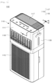
- FIG. 1 is a perspective diagram illustrating an air humidification and purification device 100 according to an embodiment of the present disclosure.
- FIG. 2 is a perspective diagram illustrating a state in which a water container 130 is separated from a water tank unit 140 in the air humidification and purification device 100 illustrated in FIG. 1 .
- FIG. 3 is a perspective diagram illustrating the water tank unit 140 and the humidification member 160 illustrated in FIG. 2 .
- FIG. 4 is an exploded perspective diagram illustrating the water tank unit 135 and the humidification member 135 illustrated in FIG. 3 .
- FIG. 4 further illustrates the water tank unit 135 for ease of description.
- FIG. 5 is a cross-sectional diagram illustrating the air humidification and purification device 100 illustrated in FIG.
- FIG. 6 is a perspective diagram illustrating a flow path regulating member 180 provided in an air humidification and purification device 100 according to an embodiment of the present disclosure.
- FIG. 7 is a perspective diagram illustrating a water supply regulating member 150 illustrated in FIG. 4 .
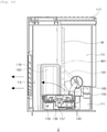
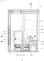
- FIG. 8 is diagrams illustrating the air humidification and purification device 100 illustrated in FIG. 1 , where the lower portion is a longitudinal cross-sectional diagram illustrating a central portion, and the upper portion is a longitudinal cross-sectional diagram illustrating in a state in which a water container 130 is removed, taken along line A-A' in FIG. 1 .
- the air humidification and purification device 100 may include a housing 110 forming the exterior of the product, an air purification filter 120 for filtering and purifying air, a water container 130 accommodating water for humidification and having a water supply valve member 135, a water tank unit 140 receiving water from the water container 130, a humidification member 160 performing humidification, a blowing part 170 providing blowing power, air flow path part F1, F2, and F3 formed between the suction port 115 and the discharge port 116, a flow path regulating member 180 for regulating the air flow, and a driving part M for providing a rotational force.
- the air humidification and purification device 100 may include a control part C for controlling the driving of the air humidification and purification device 100 and a water supply regulating member 150 operating to open and close the water supply valve member 135.
- the air humidification and purification device 100 may include a housing body 111 forming the exterior, a suction port 115 through which external air is suctioned into the housing body 111, and an discharge port 116 through which air passing through the housing body 111 is discharged externally of the housing body 111.
- the discharge port 116 may be divided into a humidified air discharge port 118 through which air flowing in from the suction port 115 is discharged through the air purification filter 120 and the humidification member 160 described later, and a purified air discharge port 117 through which air is discharged without passing through the humidification member 160.
- the suction port 115 may be formed in the lower front portion of the housing 110
- the humidified air discharge port 118 may be formed in the upper front portion of the housing 110
- the purified air discharge port 117 may be formed on the upper surface of the housing 110.
- the installation positions of the suction port 115 and the discharge port 116 (117, and 118) and the number of the suction port 115 and the discharge port 116, 117, and 118 may be varied.
- the suction port 115 may be installed on a plurality of surfaces among the front, rear, left, and right surfaces of the housing 110 so as to suction air in various directions, and the installation positions of the humidified air discharge port 118 and the purified air discharge port 117 and the number of the humidified air discharge port 118 and the purified air discharge port 117 may also be varied.
- the air purification filter 120 may be provided within the housing 110 and may be configured to filter (purify) air flowing in from the suction port 115, and may be disposed on the rear end of the suction port 115. Also, the air purification filter 120 may be installed on the front end of the blowing part 170 such that air flowing in from the suction port 115 may be filtered by the air purification filter 120 and may flow into the blowing part 170.
- the air purification filter 120 may be configured in a rectangular shape corresponding to the shape and cross-sectional area of the air flow path on the rear end of the suction port 115, and accordingly, the entire air flowing in through the suction port 115 of the housing 110 may pass through the air purification filter 120.
- the shape of the air purification filter 120 is not limited to the above-described rectangular shape, and various types of known filters may be used.
- the air purification filter 120 may be configured as a three-dimensional filter having a circular or angular cross-sectional surface and having a space (hollow) formed therein.
- the air purification filter 120 may be selected from among filters having various shapes and functions, and the type of the air purification filter 120, the number of the air purification filter 120, the shape of the air purification filter 120 are not limited to the example illustrated in FIG. 8 , and may be varied.
- the water container 130 may include a water container body 131 for accommodating water for humidification therein, and a water supply valve member 135 opening and closing to allow water accommodated in the water container body 131 to be discharged.
- the water container 130 may be configured to be separated from the air humidification and purification device 100 so as to easily fill the water container body 131 with water.
- the water container body 131 of the water container 130 may be configured to form a portion of the exterior of the housing 110 and may be separated from the housing 110, but an example embodiment thereof is not limited thereto.
- the water supply valve member 135 may be installed in a cap structure screwed to an inlet (an inlet port) of the water container body 131.
- the water supply valve member 135 may include an opening/closing part 136 elastically supported by an elastic means (a spring), and may have a mechanical valve structure in which a closed state is maintained while the opening/closing part 136 is not pressed, and an open state is maintained while the opening/closing part 136 is pressed.
- the water supply valve member 135 may be generally used for the water container 130 of a general humidifier, and thus, a detailed description thereof will not be provided.
- the water tank unit 140 may be installed within the housing 110 and may accommodate water supplied from the water container 130 by opening the water supply valve member 135.
- the water tank unit 140 may include a water tank body 141 for accommodating water, and a water tank cover 145 for covering at least a portion of the upper portion of the water tank body 141. Also, an opening cover 143 for blocking the through-hole 112b (in FIG. 2 ) when the water tank unit 140 is mounted on the opening 113 of the housing 110 may be installed on the upper side of the water tank cover 145.
- the water tank cover 145 may include a humidification member mounting opening 146 for mounting the humidification member 160, a water tank seating part 148 on which the water container 130 is seated, and an installation groove 147 in which the water supply regulating member 150 described later is installed.
- the water tank unit 140 may be installed to be separated from the housing 110 by sliding while the water container 130 is separated from the housing 110.
- the humidification member (humidification filter) 160 may perform humidification by vaporization (by blowing) using water supplied to the water tank body 141 of the water tank unit 140, and may be installed adjacent to the humidified air discharge port 118 and disposed side by side with the front of the housing 110
- the humidification member 160 may be disposed on the rear end of the blowing part 170 on the air flow path, and accordingly, air flowing by operation of the blowing part 170 may be humidified while passing through the humidification member 160, and may be discharged through the humidified air discharge port 118.
- the air purification filter 120 is disposed on the front end of the blowing part 170 and the humidification member 160 is disposed on the rear end of the blowing part 170, when only an air purifying function is performed, the flowing of air filtered in the air purification filter 120 to the humidification member 160 may be limited, and accordingly, air purifying efficiency may increase. Also, even when the blowing fan provided in the blowing part 170 is driven even at a relatively low RPM and low power, a sufficient amount of discharge may be secured and noise may be reduced. Further, when humidification is performed in the blowing part 170 the flow path switching of the flow path regulating member 180 described later, as the entire discharged air flows toward the humidification member 160, the humidification efficiency may increase.
- the humidification member 160 may be configured to have a material having excellent hygroscopicity or a shape so as to sufficiently absorb water contained in the water tank unit 140.
- the humidification member 160 may be configured to be immersed in water accommodated in the water tank body 141 as illustrated in FIGS. 2 to 4 .
- the humidification member 160 is not limited to the above-described structure, and when humidification by vaporization is possible, various known vaporization-based humidification structures such as a rotating disk-shaped humidification member may be used.
- the humidification member 160 may be mounted on and separated from the water tank unit 140 through the humidification member mounting opening 146 formed in the water tank cover 145. Also, the humidification member 160 may be separated from the housing 110 by sliding while the water container 130 is separated from the housing 110 and is mounted on the water tank unit 140.
- the blowing part 170 may provide blowing force to allow air flowing in from the suction port 115 to flow to the discharge port 116 (117 and 118) via the air flow path part F1, F2, and F3 formed between the suction port 115 and the discharge port 116 (117 and 118).
- the air flow path part F1, F2, and F3 may include a blowing flow path F1 disposed on the discharge port side of the blowing part 170, a purification flow path F2 through which air from the blowing flow path F1 flows to the purified air discharge port 117, and a humidification flow path F3 which air from the blowing flow path F1 flows to the humidified air discharge port 118.
- the specific air flow path of the air flow path part F1, F2, and F3 may be varied depending on the positions of the suction port 115 and the discharge port 116 (117 and 118), and the suction/discharge position and direction of the blowing part 170.
- the blowing part 170 may include a blowing fan for flowing air, and a fan motor for driving the blowing fan, similarly to a general blowing device used in an air purifier.
- the blowing part 170 may be disposed on the rear of the air purification filter 120 with respect to the air flow path and may have a structure in which air is suctioned from one side of the blowing part 170, but the installation position and the suctioning structure of the blowing part 170 is not limited to the examples illustrated in FIG. 8 and may be varied.
- the blowing fan provided in the blowing part 170 may have a double suction structure in which air is suctioned from both sides of the blowing part.
- the flow path regulating member 180 may be disposed to be able to rotate in the air flow path portion F1, F2, and F3, and may regulate the air flow to the discharge port 116 (117 and 118).
- the flow path regulating member 180 may switch the flow path such that air flowing through the air flow path part F1, F2, and F3 to pass through at least one of the humidified air discharge port 118 and the purified air discharge port 117.
- the flow path regulating member 180 may be configured to rotate between the purification mode position (see FIG. 9 ) in which air filtered by the air purification filter 120 and discharged from the blowing part 170 may flow to the purified air discharge port 117 via the purification flow path F2, and a humidification mode position (see FIG. 10 ) in which air from the blowing part 170 may flow to the humidified air discharge port 118 via the humidification flow path F3. That is, air purified through the air purification filter 120 may pass through the humidification member 160 and may be discharged through the humidified air discharge port 118 in a humidified state when the flow path regulating member 180 is in the humidification mode position illustrated in FIG. 10 , and when the flow path regulating member 180 is in the purification mode position illustrated in FIG. 9 , air may be discharged through the purified air discharge port 117 without passing through the humidification member 160.
- the flow path regulating member 180 may be disposed in a third position (a drying mode position) disposed between the purification mode position and the humidification mode position (see FIG. 11 ), and in the case, air from the blowing part 170 may be branched into the purification flow path F2 and the humidification flow path F3 and may flow to both the purified air discharge port 117 and the humidified air discharge port 118.
- the flow path regulating member 180 may include a body part 181 configured to cross the air flow path part F1, F2, and F3 to open and close at least a portion of the air flow path part F1, F2, and F3, and a pressing part 185 configured to pressurize the water supply regulating member 150 described later as the body part 181 rotates around the rotary shaft part 183.
- the flow path regulating member 180 may be configured to rotate by a driving part M including a motor and other components. Accordingly, by controlling the driving part M by the control part C, the flow path regulating member 180 may rotate between the purification mode position and the humidification mode position.
- the opening and closing of the water supply valve member 135 provided in the water container 130 may be configured to be performed by rotation of the flow path regulating member 180.
- the flow path regulating member 180 may be configured to open the water supply valve member 135 provided in the water container 130 such that water may be supplied from the water container 130 to the water tank unit 140.
- the opening and closing of the water supply valve member 135 provided in the water container 130 is performed by rotation of the flow path regulating member 180, the water supply from the water container 130 to the water tank unit 140 may be efficiently blocked, and a driving means for supplying water to the water tank unit 140 may not be necessary.
- the air humidification and purification device 100 may further include a water supply regulating member 150 installed in the water tank unit 140 and operating to open and close the water supply valve member 135 provided in the water container 130
- the flow path regulating member 180 may be configured to pressurize the water supply regulating member 150 to open the water supply valve member 135 provided in the water container 130.
- the water supply regulating member 150 may be installed in the water tank cover 145 of the water tank unit 140 as illustrated in FIGS. 3 and 4 .
- the water supply regulating member 150 may include a body part 151, a contact part 155 disposed on one side of the body part 151 and able to be pressed by the pressing part 185 of the flow path regulating member 180, a pushing part 157 formed on the other side of the body part 151 and able to pressurize the water supply valve member 135 of the water container 130, and a rotary shaft part 153 disposed between the contact part 155 and the pushing part 157 and coupled to the installation groove 147 formed in the water tank cover 145.
- the water supply regulating member 150 may be configured to be perform seesaw movement with respect to the rotary shaft part 153 (see the arrow in FIG. 3 ). Also, referring to FIGS. 3 , 5 , 8 and 10 , when the pressing part 185 of the flow path regulating member 180 pressurizes the contact part 155 downwardly, the pushing part 157 may move upwardly with respect to the rotary shaft part 153, such that the water supply valve member 135 may be opened. That is, as illustrated in FIG.
- the opening/closing part 136 provided in the water supply valve member 135 may move upwardly, such that the space into which water may flow may be formed around the opening/closing part 136, and accordingly, water may be supplied from the water container 130 to the water tank unit 140.
- the installation groove 147 of the water tank cover 145 in which the water supply regulating member 150 is installed may be configured as a groove in which, while the water supply regulating member 150 is installed in the water tank cover 145, the contact part 155 side (upper side) may be opened and the pushing part 157 side (lower side) may be closed. Accordingly, the water supply regulating member 150 may maintain a stable position without being separated from the installation groove 147 even when the pressing part 185 of the flow path regulating member 180 pressurizes the contact part 155 of the water supply regulating member 150.
- the housing 110 may include an opening 113 in which the water container 130 is installed, and a partition 112 for partitioning the air flow path part F1, F2, and F3.
- the water supply regulating member 150 may be disposed in the opening 113 which may be the outer side of the partition 112, and the flow regulating member 180 may be disposed in the air flow path part F1, F2, and F3 which may be the inner side of the partition 112.
- the pressing part 185 of the flow path regulating member 180 may be exposed to the opening 113 through the through-hole 112a formed in the partition 112 to pressurize the contact part 155 of the water supply regulating member 150 disposed in the opening 113.
- the humidification member 160 is also disposed in the humidification flow path F3 of the air flow path part F1, F2, and F3 which may be the inner side of the partition 112, another through-hole 112b may be formed in the partition 112 to allow the water tank unit 140 on which the humidification member 160 is mounted may be disposed in the humidification path F3, and an opening cover 143 may be provided on the water tank unit 140 to close the through-hole 112b.
- the contact part 155 of the water supply regulating member 150 when the water tank unit 140 is installed in the housing 110, when the contact part 155 of the water supply regulating member 150 is lifted upwardly, the contact part 155 may be in contact with and may interfere with the side surface of the pressing part 185 of the flow path regulating member 180. In the case, the water tank unit 140 may not be properly installed, such that water may not be supplied from the water container 130, which may be problematic.
- the contact part 155 side may be inclined in a downward direction with respect to the rotary shaft part 153 while the water supply regulating member 150 is installed on the water tank cover 145.
- the water supply regulating member 150 may be configured to include a weight part 159 for adding weight to one side of the body part 151, that is, the contact part 155 side. Accordingly, when the water tank unit 140 is separated from the housing 110, the contact part 155 may be inclined downwardly by the weight of the weight part 159. Therefore, even when the water tank unit 140 is mounted on the housing 110, the contact part 155 of the water supply regulating member 150 may not be interfered with the pressing part 185 of the flow path regulating member 180, such that the water tank unit 140 may be stably installed.
- the air humidification and purification device 100 may further include a control part C (in FIG. 6 ) for controlling operation of the flow path regulating member 180 and the blowing part 170.
- the control part C may regulate the rotational position of the flow path regulating member 180 in response to the purification mode and the humidification mode and may drive the blowing part 170.
- the controller C may move the flow path regulating member 180 to the drying mode position (the third position) disposed between the humidification mode position and the purification mode position, such that the humidification member 160 is dried after the humidification ends.
- the blowing part 170 may be driven to dry water absorbed in the humidification member 160 and/or water contained in the water tank unit 140.
- the drying mode may be performed for a predetermined period of time required for drying the humidification member 160 and/or the water tank unit 140 through time control, but an example embodiment thereof is not limited thereto.
- the flow path regulating member 180 may be disposed in the vertical direction to open the purification flow path F2 of the air flow path part F1, F2, and F3.
- the air blown from the blowing part 170 may be discharged through the purified air discharge port 117 via the open purification flow path F2 due to flow resistance of the humidification member 160 installed in the humidification flow path F3.
- the pressing part 185 of the flow path regulating member 180 may be spaced apart from the contact part 155 of the water supply regulating member 150, such that the pushing part 157 of the flow path regulating member 180 may not pressurize the water supply valve member 135. Accordingly, the opening/closing part 136 provided in the water supply valve member 135 may maintain a closed state by the elastic force of the elastic means (the spring), and water may not be supplied from the water container 130 to the water tank unit 140.
- the flow path regulating member 180 may be disposed in a direction of crossing the transverse cross-sectional surface of the purification flow path F2, such as, for example, in an oblique direction, to close the purification flow path F2 of the air flow path part F1, F2, and F3. That is, the flow path regulating member 180 may be disposed such that the upper end of the body part 181 may be inclined toward the humidified air discharge port 118.
- the upper end of the body part 181 of the flow path regulating member 180 may be adjacent to a partition wall W and the lower end may be adjacent to the opposite side of the partition wall W, such that the air flow to the purification flow path F2 may be blocked and air flowing through the air flow path part may flow into the humidification path F3 through the through-hole WH formed in the partition wall W. Accordingly, the air blown from the blowing part 170 may be humidified through the humidification member 160 and discharged externally of the housing 110 through the humidified air discharge port 118.
- the pressing part 185 of the flow path regulating member 180 may be in contact with the contact part 155 of the water supply regulating member 150 and may pressurize the contact part 155, the contact part 155 of the water supply regulating member 150 may move in a downward direction with respect to the rotary shaft part 153, and the pushing part 157 of the water supply regulating member 150 may move in the upward direction with respect to the rotary shaft part 153. Accordingly, the pushing part 157 of the flow path regulating member 180 may pressurize the opening/closing part 136 of the water supply valve member 135 upwardly, such that the opening/closing part 136 may move upwardly. Accordingly, the opening/closing part 136 may be opened, such that water may be supplied from the water container 130 to the water tank unit 140.
- the flow path regulating member 180 may have the third position (the drying mode position) disposed between the purification mode position and the humidification mode position.
- the third position the drying mode position
- the humidification member 160 and/or the water tank unit 140 may be dried.
- the inclination angle of the flow path regulating member 180 in the vertical direction may be smaller than the inclination angle in the vertical direction in the humidification mode position in FIG. 10 .
- the upper end of the flow path regulating member 180 may be slightly spaced apart from the partition wall W and the lower end may be slightly spaced apart from the opposite wall of the partition wall W, such that some air may flow into the purification flow path F2 and some air may flow into the humidification path F3 through the through-hole WH formed in the partition wall W.
- the humidification member 160 may be dried.
- the humidification member 160 may be configured to absorb moisture of the water contained in the water tank unit 140, and in the case, water contained in the water tank unit 140 may be dried according to the drying of the humidification member 160.
- the opening/closing part 136 provided in the water supply valve member 135 may be closed by the elastic force of the elastic means (spring), and the water supply from the water container 130 to the water tank unit 140 may be blocked.
- the position of the flow path regulating member 180 in the drying mode may be determined to sufficiently secure the amount of air blown into the humidification flow path F3.
- the position of the flow path regulating member 180 in the drying mode may slightly rotate from the humidification mode position such that the contact between the pressing part 185 and the contact part 155 of the water supply regulating member 150 may be released and the opening/closing part 136 may be closed.
- the controller C may move the flow path regulating member 180 from the humidification mode position to the drying mode position between the humidification mode position and the purification mode position after the humidification mode ends, such that the humidification member 160 may be dried.
- the blowing part 170 may be driven to dry the water absorbed in the humidification member 160 and/or the water contained in the water tank unit 140.
- the drying mode may be performed not only after the humidification mode ends, and the drying mode may be performed by a user selection or may be performed after the purification mode ends.
- the drying mode may be performed for a predetermined period of time necessary for drying the humidification member 160 and/or the water tank unit 140 through time control, but an example embodiment thereof is not limited thereto.
- the humidification mode in which water is supplied by a simple manipulation of rotating the flow path regulating member 180 and the purification mode in which humidification is not performed may be easily implemented, and the drying mode for drying the humidification member 160 may also be easily performed.
- water may be supplied to the water tank unit 140 only when the flow path regulating member 180 is in the humidification mode position, and water supply to the water tank unit 140 may be blocked in the purification mode and the drying mode position, such that, by performing the drying mode, moisture present in the water tank unit 140 and/or the humidification member 160 may be removed. Accordingly, contamination and bacterial generation in the water tank unit 140 and/or the humidification member 160 may be significantly reduced.
Landscapes
- Engineering & Computer Science (AREA)
- Chemical & Material Sciences (AREA)
- Combustion & Propulsion (AREA)
- Mechanical Engineering (AREA)
- General Engineering & Computer Science (AREA)
- Chemical Kinetics & Catalysis (AREA)
- Signal Processing (AREA)
- Physics & Mathematics (AREA)
- Fuzzy Systems (AREA)
- Mathematical Physics (AREA)
- Air Humidification (AREA)
Abstract
Description
- The present disclosure relates to an air humidification and purification device having an air purification function and a humidification function, and more particularly, an air humidification and purification device which may regulate a flow path to perform an air purification function and a humidification function.
- An air purifier is a device purifying polluted air into fresh air, and may perform a function of removing dust and germs along with odors by allowing incoming air to pass through an air purification filter.
- A general air humidification and purification device may include a blowing fan (a blowing part) for suctioning air to be purified and a purification filter for purifying air.
- Meanwhile, the air purifier may include a humidification member (humidification filter) to supply humidified air in addition to the air purification filter. As described above, an air humidification and purification device having a humidification function may control indoor humidity by discharging air containing moisture.
- A general air humidification and purification device may use vaporization-type (blowing-type) humidification as in a method of vaporizing by blowing water absorbed by a humidification member after the humidification member is immersed in a water tank or vaporizing by blowing water on a plurality of disks by rotating the disks while a portion of the disks are immersed in a water tank.
- In the case of such a general humidifying purifier, a water container may be mounted on a water tank, and water may be supplied from the water container to the water tank regardless of whether the humidification mode is performed, such that the water tank may maintain a constant water level. Accordingly, the water supply from the water container to the water tank may be stopped only when the entire water contained in the water container is emptied, and the water in the water tank may be completely removed only when the entire water contained in the water tank is evaporated.
- Accordingly, in the general air humidification and purification device, since water may remain at a predetermined water level in the water tank even after humidification ends, mold, scale, scale, odor, or bacteria may proliferate in the water tank and/or the humidification member.
- Meanwhile, in an air humidification and purification device, a humidification member may be installed side by side with the air purification filter on the rear end of the air purification filter, and a blowing fan for suctioning air may be installed on the rear end of the humidification member. In the case, some of the air passing through the air purification filter may flow into the blowing fan through the humidification member, but the other air may flow directly into the blowing fan without passing through the humidification member. Therefore, since the general air humidification and purification device does not have a structure in which the entirety of air passing through the air purification filter may pass through the humidification member, the humidification efficiency may be lowered when a humidifying mode is performed.
- To resolve the problem, a flow path regulating member for controlling the flowing direction of air may be used to increase the flow rate of the air passing through the air purification filter is supplied to the humidification member in the humidification mode. However, even when the flow path regulating member is used, the entirety of air passing through the air purification filter is not supplied to the humidification member, such that there may be a limitation in improving the humidification efficiency.
- Also, in a general air humidification and purification device, some of the air filtered through the air purification filter may be supplied to the humidification member even in a purification-only mode in which humidification is not performed, such that the air purification efficiency may degrade, which may be problematic. That is, in the purification-only mode, an unnecessary humidification member may act as a flow resistance against air passing through the air purification filter. Therefore, in a general air humidification and purification device, to achieve the same amount of air discharge as in the case in which air does not pass through a humidification member, the driving RPM of the blowing fan may need to be increased, such that power consumption and noise may increase, which may be problematic.
- One aspect of the present disclosure is to provide an air humidification and purification device which may efficiently block a water supply from a water container to a water tank unit.
- Also, one aspect of the present disclosure is to provide an air humidification and purification device which may significantly reduce contamination or bacterial generation in a water tank unit and/or a humidification member (a humidification filter).
- Further, one aspect of the present disclosure is to provide an air humidification and purification device which may supply water to a water tank unit only in a humidification mode.
- Also, one aspect of the present disclosure is to provide an air humidification and purification device which may supply water to a water tank unit according to flow path regulation without using a driving means to supply water to a water tank unit.
- Also, one aspect of the present disclosure is to provide an air humidification and purification device which may easily implement a humidification mode and a purification mode.
- Also, one aspect of the present disclosure is to provide an air humidification and purification device which may improve humidification efficiency and air purification efficiency.
- According to one aspect of the present disclosure, an air humidification and purification device includes a housing having a suction port through which air is suctioned, and a discharge port through which air is discharged; a blowing part provided in the housing, and providing blowing force to allow air flowing in from the suction port to flow to the discharge port; an air purification filter disposed in the housing and filtering air flowing in from the suction port; a water container provided in the housing; a water tank unit for receiving water from the water container; a humidification member for performing humidification using water supplied to the water tank unit; an air flow path part formed between the suction port and the discharge port, and in which air flowing from the suction port flows; a flow path regulating member rotatably disposed in the air flow path part; and a driving part for providing rotational force to the flow path regulating member, wherein the water container includes a water supply valve member opening and closing to allow water contained therein to be discharged, wherein the flow path regulating member includes a rotary shaft part formed as a center of rotation, a body part rotating integrally with the rotary shaft part, and configured to cross the air flow path part to open and close at least a portion of the air flow path part, and a pressing part rotating integrally with the rotary shaft part, and providing pressing force to open water supply valve member, and wherein, when the flow path regulating member rotates, a direction of air flow in the air flow path part changes by the body part, and the water supply valve member opens and closes by the pressing part.
- The discharge port may include a humidified air discharge port through which air flowing in from the suction port is discharged through the air purification filter and the humidification member, and a purified air discharge port through which air is discharged without passing through the humidification member.
- The flow path regulating member may switch a flow path such that air flowing through the air flow path part may be discharged through at least one of the humidified air discharge port and the purified air discharge port.
- The flow path regulating member may have a purification mode position in which air flowing through the air flow path part is discharged through the purified air discharge port, and a humidification mode position in which air is discharged through the humidified air discharge port. The flow path regulating member may be configured to open the water supply valve member in the humidification mode position.
- The flow path regulating member may further include a third position disposed between the purification mode position and the humidification mode position such that air flowing through the air flow path part may be discharged through the purified air discharge port and the humidified air discharge port.
- The air humidification and purification device may further include a control part for controlling driving of the flow path regulating member and the blowing part, and the control part may move the flow path regulating member to the third position such that the humidification member may be dried after the humidification ends.
- The air humidification and purification device may further include a water supply regulating member installed in the water tank unit and operating to open and close the water supply valve member, and the flow path regulating member may open the water supply valve member by pressurizing the water supply regulating member.
- The water tank unit may include a water tank body for accommodating water therein, and a water tank cover for covering at least a portion of an upper portion of the water tank body, and the water supply regulating member is installed on the water tank cover.
- The water supply regulating member may include a body part, a contact part formed on one side of the body part and pressed by the flow path regulating member, a pressing part formed on the other side of the body part and pressurizing the water supply valve member, and a rotary shaft part disposed between the contact part and the pressing part and coupled to an installation groove formed in the water tank cover.
- The water supply regulating member may be configured to be able to perform seesaw movement with respect to the rotating shaft, and wherein, when the flow regulating member pressurizes the contact part downwardly, the pressing part may move upwardly and may open the water supply valve member.
- The water supply regulating member may include a weight part for adding weight to one side of the body part such that the contact part side may be inclined downwardly with respect to the rotary shaft part in a state in which the water supply regulating member is installed in the water tank cover.
- The installation groove may be configured as a groove in which the contact part side is opened and the pressing part side is closed in a state in which the water supply regulating member is installed on the water tank cover.
- The housing may include an opening in which the water container is installed and a partition for dividing the air flow path part therein, and the water supply regulating member may be disposed in the opening, and the pressing part of the flow path regulating member may be exposed to the opening through a through-hole formed in the partition so as to pressurize the contact part.
- The water tank unit and the humidification member may be installed to be separated from the housing by sliding while the water container is separated from the housing.
- The humidification member may be disposed on a rear end of the blowing part and may be configured to humidify air discharged from the blowing part.
- The suction port may be formed in a front lower portion of the housing, the humidified air discharge port is formed on a front upper portion of the housing, the purified air discharge port is formed on an upper surface of the housing, and the humidification member is installed side by side with a front surface of the housing. In this case, the flow path regulating member may be disposed in a vertical direction when air is discharged through the purified air discharge port, and an upper end thereof may be inclined toward the humidified air discharge port when air is discharged through the humidified air discharge port.
- According to one aspect of the present disclosure, an air humidification and purification device includes housing having a suction port through which air is suctioned, and a discharge port through which air is discharged; an air purification filter disposed in the housing and filtering air flowing in from the suction port; a humidification member for performing humidification using water supplied to the water tank unit; a blowing part providing blowing force to allow air flowing in from the suction port to flow to the discharge port via an air flow path part formed between the suction port and the discharge port; a flow path regulating member rotatably disposed in the air flow path part, and rotating between a humidification mode position in which air flowing through the air flow path part is discharged via the humidification member, and a purification mode position in which air is discharged without passing through the humidification member, wherein the flow path regulating member is configured to open the water supply valve member provided in the water container such that water is supplied from the water container to the water tank unit in the humidification mode position.
- The flow path regulating member may be disposed in a third position disposed between the purification mode position and the humidification mode position, and the water supply valve member may have a closed state in the purification mode position and the third mode position.
- According to an embodiment of the present disclosure, since the opening and closing of a water supply valve member provided in a water container is performed by rotation of the flow path regulating member, an effect of effectively blocking water supply from a water container to a water tank unit may be obtained.
- Also, according to an embodiment of the present disclosure, water may be supplied to the water tank unit only when a flow path regulating member is in a humidification mode position, and water supply to the water tank unit may be blocked in a drying mode position, such that an effect that moisture present in the water tank unit and/or the humidification member may be removed by the drying mode performed when the humidification mode ends and that contamination or bacterial generation in the water tank unit and/or the humidification member may thus be significantly reduced may be obtained.
- Further, according to an embodiment of the present disclosure, an effect that a driving means for supplying water to the water tank unit may not be necessary as water supply to the water tank unit and blocking of the water supply may be possible only by rotation of the flow path regulating member rotating between the purification mode position and the humidification mode position may be obtained.
- Also, according to an embodiment of the present disclosure, an effect that the water tank unit may be stably installed by avoiding the interference between the water supply regulating member and the flow path regulating member when the water tank unit is installed in a housing may be obtained.
- Also, according to an embodiment of the present disclosure, an effect that the humidification mode and the purification mode may be easily implemented by a simple manipulation of rotating the flow path regulating member may be obtained.
- Also, according to an embodiment of the present disclosure, the air purification filter may be disposed on the front end of the blowing part and the humidification member may be disposed on the rear end of the blowing part, such that, when the purification mode is performed, the flow of air filtered by the air purification filter to the humidification member may be limited, which may increase air purifying efficiency, and accordingly, even when the blowing fan provided in the blowing part is driven at a relatively low RPM and low power, the sufficient amount of discharge may be secured and noise be reduced. Further, an effect that, by allowing the discharged air to flow toward the humidification member when the humidification mode is performed, humidification efficiency may increase may be obtained.
-
-
FIG. 1 is a perspective diagram illustrating an air humidification and purification device according to an embodiment of the present disclosure; -
FIG. 2 is a perspective diagram illustrating a state in which a water container is separated from a water tank unit in the air humidification and purification device illustrated inFIG. 1 ; -
FIG. 3 is a perspective diagram illustrating the water tank unit and the humidification member illustrated inFIG. 2 ; -
FIG. 4 is an exploded perspective diagram illustrating the water tank unit and the humidification member illustrated inFIG. 3 ; -
FIG. 5 is a cross-sectional diagram illustrating the air humidification and purification device illustrated inFIG. 1 from which a water container body is removed, taken along line A-A' inFIG. 1 ; -
FIG. 6 is a perspective diagram illustrating a flow path regulating member provided in an air humidification and purification device according to an embodiment of the present disclosure; -
FIG. 7 is a perspective diagram illustrating a water supply regulating member illustrated inFIG. 4 ; -
FIG. 8 is diagrams illustrating the air humidification and purification device illustrated inFIG. 1 , where the lower portion is a longitudinal cross-sectional diagram illustrating a central portion, and the upper portion is a longitudinal cross-sectional diagram in a state in which a water container is removed, taken along line A-A' inFIG. 1 ; -
FIG. 9 is an enlarged diagram illustrating a state in a purification mode with respect to portion B inFIG. 8 ; -
FIG. 10 is an enlarged diagram illustrating a state in a humidification mode with respect to portion B inFIG. 8 ; and -
FIG. 11 is an enlarged diagram illustrating a state in a drying mode with respect to portion B inFIG. 8 . - Hereinafter, preferable embodiments of the present disclosure will be described with reference to the accompanying drawings. However, the embodiments of the present disclosure may be modified in various other forms, and the scope of the present disclosure is not limited to the embodiments described below. Also, the embodiments of the present disclosure are provided to more completely describe the present disclosure to a person having ordinary skill in the art. The shapes and sizes of the elements in the drawings may be exaggerated for clearer description.
- Also, in the present specification, a singular term may include a plural form unless otherwise indicated, and the same reference numerals refer to the same element or a corresponding element throughout the embodiments.
- In the description below, the embodiments of the present disclosure will be described with reference to the drawings.
- First, an air humidification and
purification device 100 will be described with reference toFIGS. 1 to 8 according to an embodiment of the present disclosure. -
FIG. 1 is a perspective diagram illustrating an air humidification andpurification device 100 according to an embodiment of the present disclosure.FIG. 2 is a perspective diagram illustrating a state in which awater container 130 is separated from awater tank unit 140 in the air humidification andpurification device 100 illustrated inFIG. 1 .FIG. 3 is a perspective diagram illustrating thewater tank unit 140 and thehumidification member 160 illustrated inFIG. 2 .FIG. 4 is an exploded perspective diagram illustrating thewater tank unit 135 and thehumidification member 135 illustrated inFIG. 3 .FIG. 4 further illustrates thewater tank unit 135 for ease of description.FIG. 5 is a cross-sectional diagram illustrating the air humidification andpurification device 100 illustrated inFIG. 1 from which awater container body 131 is removed, taken along line A-A' inFIG. 1 .FIG. 6 is a perspective diagram illustrating a flowpath regulating member 180 provided in an air humidification andpurification device 100 according to an embodiment of the present disclosure.FIG. 7 is a perspective diagram illustrating a watersupply regulating member 150 illustrated inFIG. 4 .FIG. 8 is diagrams illustrating the air humidification andpurification device 100 illustrated inFIG. 1 , where the lower portion is a longitudinal cross-sectional diagram illustrating a central portion, and the upper portion is a longitudinal cross-sectional diagram illustrating in a state in which awater container 130 is removed, taken along line A-A' inFIG. 1 . - As illustrated in
FIGS. 1 to 8 , the air humidification andpurification device 100 according to an embodiment of the present disclosure may include ahousing 110 forming the exterior of the product, anair purification filter 120 for filtering and purifying air, awater container 130 accommodating water for humidification and having a watersupply valve member 135, awater tank unit 140 receiving water from thewater container 130, ahumidification member 160 performing humidification, a blowingpart 170 providing blowing power, air flow path part F1, F2, and F3 formed between thesuction port 115 and thedischarge port 116, a flowpath regulating member 180 for regulating the air flow, and a driving part M for providing a rotational force. Also, the air humidification andpurification device 100 according to an embodiment of the present disclosure may include a control part C for controlling the driving of the air humidification andpurification device 100 and a watersupply regulating member 150 operating to open and close the watersupply valve member 135. - First, as illustrated in
FIGS. 1 and2 , the air humidification andpurification device 100 according to an embodiment of the present disclosure may include ahousing body 111 forming the exterior, asuction port 115 through which external air is suctioned into thehousing body 111, and andischarge port 116 through which air passing through thehousing body 111 is discharged externally of thehousing body 111. - Also, the
discharge port 116 may be divided into a humidifiedair discharge port 118 through which air flowing in from thesuction port 115 is discharged through theair purification filter 120 and thehumidification member 160 described later, and a purifiedair discharge port 117 through which air is discharged without passing through thehumidification member 160. - As illustrated in
FIG. 1 , thesuction port 115 may be formed in the lower front portion of thehousing 110, the humidifiedair discharge port 118 may be formed in the upper front portion of thehousing 110, and the purifiedair discharge port 117 may be formed on the upper surface of thehousing 110. However, the installation positions of thesuction port 115 and the discharge port 116 (117, and 118) and the number of thesuction port 115 and thedischarge port suction port 115 may be installed on a plurality of surfaces among the front, rear, left, and right surfaces of thehousing 110 so as to suction air in various directions, and the installation positions of the humidifiedair discharge port 118 and the purifiedair discharge port 117 and the number of the humidifiedair discharge port 118 and the purifiedair discharge port 117 may also be varied. - Referring to
FIG. 8 , theair purification filter 120 may be provided within thehousing 110 and may be configured to filter (purify) air flowing in from thesuction port 115, and may be disposed on the rear end of thesuction port 115. Also, theair purification filter 120 may be installed on the front end of the blowingpart 170 such that air flowing in from thesuction port 115 may be filtered by theair purification filter 120 and may flow into the blowingpart 170. - The
air purification filter 120 may be configured in a rectangular shape corresponding to the shape and cross-sectional area of the air flow path on the rear end of thesuction port 115, and accordingly, the entire air flowing in through thesuction port 115 of thehousing 110 may pass through theair purification filter 120. However, the shape of theair purification filter 120 is not limited to the above-described rectangular shape, and various types of known filters may be used. For example, theair purification filter 120 may be configured as a three-dimensional filter having a circular or angular cross-sectional surface and having a space (hollow) formed therein. - Also, the
air purification filter 120 may be selected from among filters having various shapes and functions, and the type of theair purification filter 120, the number of theair purification filter 120, the shape of theair purification filter 120 are not limited to the example illustrated inFIG. 8 , and may be varied. - The
water container 130 may include awater container body 131 for accommodating water for humidification therein, and a watersupply valve member 135 opening and closing to allow water accommodated in thewater container body 131 to be discharged. - The
water container 130 may be configured to be separated from the air humidification andpurification device 100 so as to easily fill thewater container body 131 with water. For example, as illustrated inFIGS. 1 and2 , thewater container body 131 of thewater container 130 may be configured to form a portion of the exterior of thehousing 110 and may be separated from thehousing 110, but an example embodiment thereof is not limited thereto. - The water
supply valve member 135 may be installed in a cap structure screwed to an inlet (an inlet port) of thewater container body 131. The watersupply valve member 135 may include an opening/closing part 136 elastically supported by an elastic means (a spring), and may have a mechanical valve structure in which a closed state is maintained while the opening/closing part 136 is not pressed, and an open state is maintained while the opening/closing part 136 is pressed. The watersupply valve member 135 may be generally used for thewater container 130 of a general humidifier, and thus, a detailed description thereof will not be provided. - Also, the
water tank unit 140 may be installed within thehousing 110 and may accommodate water supplied from thewater container 130 by opening the watersupply valve member 135. - Referring to
FIGS. 3 and4 , thewater tank unit 140 may include awater tank body 141 for accommodating water, and awater tank cover 145 for covering at least a portion of the upper portion of thewater tank body 141. Also, anopening cover 143 for blocking the through-hole 112b (inFIG. 2 ) when thewater tank unit 140 is mounted on theopening 113 of thehousing 110 may be installed on the upper side of thewater tank cover 145. - The
water tank cover 145 may include a humidificationmember mounting opening 146 for mounting thehumidification member 160, a watertank seating part 148 on which thewater container 130 is seated, and aninstallation groove 147 in which the watersupply regulating member 150 described later is installed. - As illustrated in
FIG. 2 , thewater tank unit 140 may be installed to be separated from thehousing 110 by sliding while thewater container 130 is separated from thehousing 110. - Also, the humidification member (humidification filter) 160 may perform humidification by vaporization (by blowing) using water supplied to the
water tank body 141 of thewater tank unit 140, and may be installed adjacent to the humidifiedair discharge port 118 and disposed side by side with the front of thehousing 110 - The
humidification member 160 may be disposed on the rear end of the blowingpart 170 on the air flow path, and accordingly, air flowing by operation of the blowingpart 170 may be humidified while passing through thehumidification member 160, and may be discharged through the humidifiedair discharge port 118. - As described above, since the
air purification filter 120 is disposed on the front end of the blowingpart 170 and thehumidification member 160 is disposed on the rear end of the blowingpart 170, when only an air purifying function is performed, the flowing of air filtered in theair purification filter 120 to thehumidification member 160 may be limited, and accordingly, air purifying efficiency may increase. Also, even when the blowing fan provided in the blowingpart 170 is driven even at a relatively low RPM and low power, a sufficient amount of discharge may be secured and noise may be reduced. Further, when humidification is performed in the blowingpart 170 the flow path switching of the flowpath regulating member 180 described later, as the entire discharged air flows toward thehumidification member 160, the humidification efficiency may increase. - The
humidification member 160 may be configured to have a material having excellent hygroscopicity or a shape so as to sufficiently absorb water contained in thewater tank unit 140. As an example, thehumidification member 160 may be configured to be immersed in water accommodated in thewater tank body 141 as illustrated inFIGS. 2 to 4 . However, thehumidification member 160 is not limited to the above-described structure, and when humidification by vaporization is possible, various known vaporization-based humidification structures such as a rotating disk-shaped humidification member may be used. - As illustrated in
FIGS. 3 and4 , thehumidification member 160 may be mounted on and separated from thewater tank unit 140 through the humidificationmember mounting opening 146 formed in thewater tank cover 145. Also, thehumidification member 160 may be separated from thehousing 110 by sliding while thewater container 130 is separated from thehousing 110 and is mounted on thewater tank unit 140. - Thereafter, the blowing
part 170 may provide blowing force to allow air flowing in from thesuction port 115 to flow to the discharge port 116 (117 and 118) via the air flow path part F1, F2, and F3 formed between thesuction port 115 and the discharge port 116 (117 and 118). - Referring to
FIG. 8 , the air flow path part F1, F2, and F3 may include a blowing flow path F1 disposed on the discharge port side of the blowingpart 170, a purification flow path F2 through which air from the blowing flow path F1 flows to the purifiedair discharge port 117, and a humidification flow path F3 which air from the blowing flow path F1 flows to the humidifiedair discharge port 118. - The specific air flow path of the air flow path part F1, F2, and F3 may be varied depending on the positions of the
suction port 115 and the discharge port 116 (117 and 118), and the suction/discharge position and direction of the blowingpart 170. - Also, the blowing
part 170 may include a blowing fan for flowing air, and a fan motor for driving the blowing fan, similarly to a general blowing device used in an air purifier. InFIG. 8 , the blowingpart 170 may be disposed on the rear of theair purification filter 120 with respect to the air flow path and may have a structure in which air is suctioned from one side of the blowingpart 170, but the installation position and the suctioning structure of the blowingpart 170 is not limited to the examples illustrated inFIG. 8 and may be varied. For example, the blowing fan provided in the blowingpart 170 may have a double suction structure in which air is suctioned from both sides of the blowing part. - The flow
path regulating member 180 may be disposed to be able to rotate in the air flow path portion F1, F2, and F3, and may regulate the air flow to the discharge port 116 (117 and 118). - Referring to
FIG. 8 , the flowpath regulating member 180 may switch the flow path such that air flowing through the air flow path part F1, F2, and F3 to pass through at least one of the humidifiedair discharge port 118 and the purifiedair discharge port 117. - For example, the flow
path regulating member 180 may be configured to rotate between the purification mode position (seeFIG. 9 ) in which air filtered by theair purification filter 120 and discharged from the blowingpart 170 may flow to the purifiedair discharge port 117 via the purification flow path F2, and a humidification mode position (seeFIG. 10 ) in which air from the blowingpart 170 may flow to the humidifiedair discharge port 118 via the humidification flow path F3. That is, air purified through theair purification filter 120 may pass through thehumidification member 160 and may be discharged through the humidifiedair discharge port 118 in a humidified state when the flowpath regulating member 180 is in the humidification mode position illustrated inFIG. 10 , and when the flowpath regulating member 180 is in the purification mode position illustrated inFIG. 9 , air may be discharged through the purifiedair discharge port 117 without passing through thehumidification member 160. - The flow
path regulating member 180 may be disposed in a third position (a drying mode position) disposed between the purification mode position and the humidification mode position (seeFIG. 11 ), and in the case, air from the blowingpart 170 may be branched into the purification flow path F2 and the humidification flow path F3 and may flow to both the purifiedair discharge port 117 and the humidifiedair discharge port 118. - Referring to
FIGS. 6 and8 , the flowpath regulating member 180 may include abody part 181 configured to cross the air flow path part F1, F2, and F3 to open and close at least a portion of the air flow path part F1, F2, and F3, and apressing part 185 configured to pressurize the watersupply regulating member 150 described later as thebody part 181 rotates around therotary shaft part 183. - Also, the flow
path regulating member 180 may be configured to rotate by a driving part M including a motor and other components. Accordingly, by controlling the driving part M by the control part C, the flowpath regulating member 180 may rotate between the purification mode position and the humidification mode position. - The opening and closing of the water
supply valve member 135 provided in thewater container 130 may be configured to be performed by rotation of the flowpath regulating member 180. - For example, when humidification is performed through the
humidification member 160, that is, when the flowpath regulating member 180 is in the humidification mode position, the flowpath regulating member 180 may be configured to open the watersupply valve member 135 provided in thewater container 130 such that water may be supplied from thewater container 130 to thewater tank unit 140. - As such, according to an embodiment of the present disclosure, since the opening and closing of the water
supply valve member 135 provided in thewater container 130 is performed by rotation of the flowpath regulating member 180, the water supply from thewater container 130 to thewater tank unit 140 may be efficiently blocked, and a driving means for supplying water to thewater tank unit 140 may not be necessary. - The air humidification and
purification device 100 according to an embodiment of the present disclosure may further include a watersupply regulating member 150 installed in thewater tank unit 140 and operating to open and close the watersupply valve member 135 provided in thewater container 130 - In the case, the flow
path regulating member 180 may be configured to pressurize the watersupply regulating member 150 to open the watersupply valve member 135 provided in thewater container 130. - The water
supply regulating member 150 may be installed in thewater tank cover 145 of thewater tank unit 140 as illustrated inFIGS. 3 and4 . - Referring to
FIGS. 3 to 5 and7 , the watersupply regulating member 150 may include abody part 151, acontact part 155 disposed on one side of thebody part 151 and able to be pressed by thepressing part 185 of the flowpath regulating member 180, a pushingpart 157 formed on the other side of thebody part 151 and able to pressurize the watersupply valve member 135 of thewater container 130, and arotary shaft part 153 disposed between thecontact part 155 and the pushingpart 157 and coupled to theinstallation groove 147 formed in thewater tank cover 145. - Accordingly, the water
supply regulating member 150 may be configured to be perform seesaw movement with respect to the rotary shaft part 153 (see the arrow inFIG. 3 ). Also, referring toFIGS. 3 ,5 ,8 and10 , when thepressing part 185 of the flowpath regulating member 180 pressurizes thecontact part 155 downwardly, the pushingpart 157 may move upwardly with respect to therotary shaft part 153, such that the watersupply valve member 135 may be opened. That is, as illustrated inFIG. 10 , when the pushingpart 157 moves upwardly, the opening/closing part 136 provided in the watersupply valve member 135 may move upwardly, such that the space into which water may flow may be formed around the opening/closing part 136, and accordingly, water may be supplied from thewater container 130 to thewater tank unit 140. - Referring to
FIGS. 3 and4 , theinstallation groove 147 of thewater tank cover 145 in which the watersupply regulating member 150 is installed may be configured as a groove in which, while the watersupply regulating member 150 is installed in thewater tank cover 145, thecontact part 155 side (upper side) may be opened and the pushingpart 157 side (lower side) may be closed. Accordingly, the watersupply regulating member 150 may maintain a stable position without being separated from theinstallation groove 147 even when thepressing part 185 of the flowpath regulating member 180 pressurizes thecontact part 155 of the watersupply regulating member 150. - Referring to
FIGS. 2 and5 , thehousing 110 may include anopening 113 in which thewater container 130 is installed, and apartition 112 for partitioning the air flow path part F1, F2, and F3. - In the case, the water
supply regulating member 150 may be disposed in theopening 113 which may be the outer side of thepartition 112, and theflow regulating member 180 may be disposed in the air flow path part F1, F2, and F3 which may be the inner side of thepartition 112. However, thepressing part 185 of the flowpath regulating member 180 may be exposed to theopening 113 through the through-hole 112a formed in thepartition 112 to pressurize thecontact part 155 of the watersupply regulating member 150 disposed in theopening 113. - Also, since the
humidification member 160 is also disposed in the humidification flow path F3 of the air flow path part F1, F2, and F3 which may be the inner side of thepartition 112, another through-hole 112b may be formed in thepartition 112 to allow thewater tank unit 140 on which thehumidification member 160 is mounted may be disposed in the humidification path F3, and anopening cover 143 may be provided on thewater tank unit 140 to close the through-hole 112b. - Referring to
FIGS. 3 and7 , when thewater tank unit 140 is installed in thehousing 110, when thecontact part 155 of the watersupply regulating member 150 is lifted upwardly, thecontact part 155 may be in contact with and may interfere with the side surface of thepressing part 185 of the flowpath regulating member 180. In the case, thewater tank unit 140 may not be properly installed, such that water may not be supplied from thewater container 130, which may be problematic. - To address the above problem, in the air humidification and
purification device 100 according to an embodiment of the present disclosure, thecontact part 155 side may be inclined in a downward direction with respect to therotary shaft part 153 while the watersupply regulating member 150 is installed on thewater tank cover 145. To the end, the watersupply regulating member 150 may be configured to include aweight part 159 for adding weight to one side of thebody part 151, that is, thecontact part 155 side. Accordingly, when thewater tank unit 140 is separated from thehousing 110, thecontact part 155 may be inclined downwardly by the weight of theweight part 159. Therefore, even when thewater tank unit 140 is mounted on thehousing 110, thecontact part 155 of the watersupply regulating member 150 may not be interfered with thepressing part 185 of the flowpath regulating member 180, such that thewater tank unit 140 may be stably installed. - The air humidification and
purification device 100 according to an embodiment of the present disclosure may further include a control part C (inFIG. 6 ) for controlling operation of the flowpath regulating member 180 and the blowingpart 170. The control part C may regulate the rotational position of the flowpath regulating member 180 in response to the purification mode and the humidification mode and may drive the blowingpart 170. Also, the controller C may move the flowpath regulating member 180 to the drying mode position (the third position) disposed between the humidification mode position and the purification mode position, such that thehumidification member 160 is dried after the humidification ends. In this state, the blowingpart 170 may be driven to dry water absorbed in thehumidification member 160 and/or water contained in thewater tank unit 140. - The drying mode may be performed for a predetermined period of time required for drying the
humidification member 160 and/or thewater tank unit 140 through time control, but an example embodiment thereof is not limited thereto. - Next, the operations in the purification mode, the humidification mode and the drying mode will be described with reference to
FIGS. 9 to 11 . - As illustrated in
FIG. 9 , in the purification mode, the flowpath regulating member 180 may be disposed in the vertical direction to open the purification flow path F2 of the air flow path part F1, F2, and F3. As such, when thebody part 181 of the flowpath regulating member 180 is installed in parallel to the purification flow path F2, the air blown from the blowingpart 170 may be discharged through the purifiedair discharge port 117 via the open purification flow path F2 due to flow resistance of thehumidification member 160 installed in the humidification flow path F3. - In the case, the
pressing part 185 of the flowpath regulating member 180 may be spaced apart from thecontact part 155 of the watersupply regulating member 150, such that the pushingpart 157 of the flowpath regulating member 180 may not pressurize the watersupply valve member 135. Accordingly, the opening/closing part 136 provided in the watersupply valve member 135 may maintain a closed state by the elastic force of the elastic means (the spring), and water may not be supplied from thewater container 130 to thewater tank unit 140. - Thereafter, as illustrated in
FIG. 10 , in the humidification mode, the flowpath regulating member 180 may be disposed in a direction of crossing the transverse cross-sectional surface of the purification flow path F2, such as, for example, in an oblique direction, to close the purification flow path F2 of the air flow path part F1, F2, and F3. That is, the flowpath regulating member 180 may be disposed such that the upper end of thebody part 181 may be inclined toward the humidifiedair discharge port 118. In the case, the upper end of thebody part 181 of the flowpath regulating member 180 may be adjacent to a partition wall W and the lower end may be adjacent to the opposite side of the partition wall W, such that the air flow to the purification flow path F2 may be blocked and air flowing through the air flow path part may flow into the humidification path F3 through the through-hole WH formed in the partition wall W. Accordingly, the air blown from the blowingpart 170 may be humidified through thehumidification member 160 and discharged externally of thehousing 110 through the humidifiedair discharge port 118. - In the case, since the
pressing part 185 of the flowpath regulating member 180 may be in contact with thecontact part 155 of the watersupply regulating member 150 and may pressurize thecontact part 155, thecontact part 155 of the watersupply regulating member 150 may move in a downward direction with respect to therotary shaft part 153, and the pushingpart 157 of the watersupply regulating member 150 may move in the upward direction with respect to therotary shaft part 153. Accordingly, the pushingpart 157 of the flowpath regulating member 180 may pressurize the opening/closing part 136 of the watersupply valve member 135 upwardly, such that the opening/closing part 136 may move upwardly. Accordingly, the opening/closing part 136 may be opened, such that water may be supplied from thewater container 130 to thewater tank unit 140. - Meanwhile, as illustrated in
FIG. 11 , the flowpath regulating member 180 may have the third position (the drying mode position) disposed between the purification mode position and the humidification mode position. When the flowpath regulating member 180 is disposed in the third position, thehumidification member 160 and/or thewater tank unit 140 may be dried. - Specifically, as illustrated in
FIG. 11 , the inclination angle of the flowpath regulating member 180 in the vertical direction may be smaller than the inclination angle in the vertical direction in the humidification mode position inFIG. 10 . In the case, the upper end of the flowpath regulating member 180 may be slightly spaced apart from the partition wall W and the lower end may be slightly spaced apart from the opposite wall of the partition wall W, such that some air may flow into the purification flow path F2 and some air may flow into the humidification path F3 through the through-hole WH formed in the partition wall W. As such, as some air passes through thehumidification member 160, thehumidification member 160 may be dried. Also, thehumidification member 160 may be configured to absorb moisture of the water contained in thewater tank unit 140, and in the case, water contained in thewater tank unit 140 may be dried according to the drying of thehumidification member 160. - Also, when the flow
path regulating member 180 rotates from the humidification mode position to the third position, the contact between thepressing part 185 of the flowpath regulating member 180 and thecontact part 155 of the watersupply regulating member 150 may be released Accordingly, the opening/closing part 136 provided in the watersupply valve member 135 may be closed by the elastic force of the elastic means (spring), and the water supply from thewater container 130 to thewater tank unit 140 may be blocked. - In the case, to increase drying efficiency, the position of the flow
path regulating member 180 in the drying mode may be determined to sufficiently secure the amount of air blown into the humidification flow path F3. For example, the position of the flowpath regulating member 180 in the drying mode may slightly rotate from the humidification mode position such that the contact between thepressing part 185 and thecontact part 155 of the watersupply regulating member 150 may be released and the opening/closing part 136 may be closed. - To perform the drying mode, the controller C may move the flow
path regulating member 180 from the humidification mode position to the drying mode position between the humidification mode position and the purification mode position after the humidification mode ends, such that thehumidification member 160 may be dried. In this state, the blowingpart 170 may be driven to dry the water absorbed in thehumidification member 160 and/or the water contained in thewater tank unit 140. - However, the drying mode may be performed not only after the humidification mode ends, and the drying mode may be performed by a user selection or may be performed after the purification mode ends.
- The drying mode may be performed for a predetermined period of time necessary for drying the
humidification member 160 and/or thewater tank unit 140 through time control, but an example embodiment thereof is not limited thereto. - As such, according to an embodiment of the present disclosure, the humidification mode in which water is supplied by a simple manipulation of rotating the flow
path regulating member 180 and the purification mode in which humidification is not performed may be easily implemented, and the drying mode for drying thehumidification member 160 may also be easily performed. - Also, according to an embodiment of the present disclosure, water may be supplied to the
water tank unit 140 only when the flowpath regulating member 180 is in the humidification mode position, and water supply to thewater tank unit 140 may be blocked in the purification mode and the drying mode position, such that, by performing the drying mode, moisture present in thewater tank unit 140 and/or thehumidification member 160 may be removed. Accordingly, contamination and bacterial generation in thewater tank unit 140 and/or thehumidification member 160 may be significantly reduced. - While the embodiments have been illustrated and described above, it will be apparent to those skilled in the art that modifications and variations could be made without departing from the scope in the embodiment as defined by the appended claims.
-
- 100.. AIR HUMIDIFICATION AND
PURIFICATION DEVICE 110..HOUSING 111.. HOUSING BODY - 112.. PARTITION 112A, 112B.. THROUGH-
HOLE 113.. OPENING - 115..
SUCTION PORT 116..DISCHARGE PORT 117.. PURIFIED AIR DISCHARGE PORT - 118.. HUMIDIFIED
AIR DISCHARGE PORT 120.. AIR PURIFICATION FILTER - 130.. WATER CONTAINER
- 131..
WATER CONTAINER BODY 135.. WATERSUPPLY VALVE MEMBER 136.. OPENING/CLOSING PART - 140..
WATER TANK UNIT 141..WATER TANK BODY 143.. OPENING COVER - 145..
WATER TANK COVER 146.. HUMIDIFICATION MEMBER MOUNTING OPENING - 147.. INSTALLATION GROOVE
- 148.. WATER
TANK SEATING PART 150.. WATER SUPPLY REGULATING MEMBER - 151.. BODY PART
- 153..
ROTARY SHAFT PART 155..CONTACT PART 157.. PUSHING PART - 159..
WEIGHT PART 160..HUMIDIFICATION MEMBER 170.. BLOWING PART - 180.. FLOW
PATH REGULATING MEMBER 181..BODY PART 183.. ROTARY SHAFT PART - 185.. PRESSING PART C.. CONTROL PART F1.. BLOWING FLOW PATH
- F2.. PURIFICATION FLOW PATH F3.. HUMIDIFICATION FLOW PATH M.. DRIVING PART
- W.. PARTITION WALL WH.. THROUGH-HOLE
Claims (20)
- An air humidification and purification device, comprising:a housing having a suction port through which air is suctioned, and a discharge port through which air is discharged;a blowing part provided in the housing, and providing blowing force to allow air flowing in from the suction port to flow to the discharge port;an air purification filter disposed in the housing and filtering air flowing in from the suction port;a water container provided in the housing;a water tank unit for receiving water from the water container;a humidification member for performing humidification using water supplied to the water tank unit;an air flow path part formed between the suction port and the discharge port, and in which air flowing from the suction port flows;a flow path regulating member rotatably disposed in the air flow path part; anda driving part for providing rotational force to the flow path regulating member,wherein the water container includes a water supply valve member opening and closing to allow water contained therein to be discharged,wherein the flow path regulating member includes:a rotary shaft part formed as a center of rotation;a body part rotating integrally with the rotary shaft part, and configured to cross the air flow path part to open and close at least a portion of the air flow path part; anda pressing part rotating integrally with the rotary shaft part, and providing pressing force to open water supply valve member, andwherein, when the flow path regulating member rotates, a direction of air flow in the air flow path part changes by the body part, and the water supply valve member opens and closes by the pressing part.
- The air humidification and purification device of claim 1, wherein the discharge port includes a humidified air discharge port through which air flowing in from the suction port is discharged through the air purification filter and the humidification member, and a purified air discharge port through which air is discharged without passing through the humidification member.
- The air humidification and purification device of claim 2, wherein the flow path regulating member switches a flow path such that air flowing through the air flow path part is discharged through at least one of the humidified air discharge port and the purified air discharge port.
- The air humidification and purification device of claim 3, wherein the flow path regulating member has a purification mode position in which air flowing through the air flow path part is discharged through the purified air discharge port, and a humidification mode position in which air is discharged through the humidified air discharge port.
- The air humidification and purification device of claim 4, wherein the flow path regulating member is configured to open the water supply valve member in the humidification mode position.
- The air humidification and purification device of claim 4, wherein the flow path regulating member further includes a third position disposed between the purification mode position and the humidification mode position such that air flowing through the air flow path part is discharged through the purified air discharge port and the humidified air discharge port.
- The air humidification and purification device of claim 6, further comprising:a control part for controlling driving of the flow path regulating member and the blowing part,wherein the control part moves the flow path regulating member to the third position such that the humidification member is dried after the humidification ends.
- The air humidification and purification device of one of claims 1 to 7, further comprising:a water supply regulating member installed in the water tank unit and operating to open and close the water supply valve member,wherein the flow path regulating member opens the water supply valve member by pressurizing the water supply regulating member.
- The air humidification and purification device of claim 8,wherein the water tank unit includes a water tank body for accommodating water therein, and a water tank cover for covering at least a portion of an upper portion of the water tank body, andwherein the water supply regulating member is installed on the water tank cover.
- The air humidification and purification device of claim 9, wherein the water supply regulating member includes a body part, a contact part formed on one side of the body part and pressed by the flow path regulating member, a pressing part formed on the other side of the body part and pressurizing the water supply valve member, and a rotary shaft part disposed between the contact part and the pressing part and coupled to an installation groove formed in the water tank cover.
- The air humidification and purification device of claim 10, wherein the water supply regulating member is configured to be able to perform seesaw movement with respect to the rotating shaft, and
wherein, when the flow regulating member pressurizes the contact part downwardly, the pressing part moves upwardly and opens the water supply valve member. - The air humidification and purification device of claim 10, wherein the water supply regulating member includes a weight part for adding weight to one side of the body part such that the contact part side is inclined downwardly with respect to the rotary shaft part in a state in which the water supply regulating member is installed in the water tank cover.
- The air humidification and purification device of claim 10, wherein the installation groove is configured as a groove in which the contact part side is opened and the pressing part side is closed in a state in which the water supply regulating member is installed on the water tank cover.
- The air humidification and purification device of claim 13,wherein the housing includes an opening in which the water container is installed and a partition for dividing the air flow path part therein,wherein the water supply regulating member is disposed in the opening, andwherein the pressing part of the flow path regulating member is exposed to the opening through a through-hole formed in the partition so as to pressurize the contact part.
- The air humidification and purification device of one of claims 1 to 7, wherein the water tank unit and the humidification member are installed to be separated from the housing by sliding while the water container is separated from the housing.
- The air humidification and purification device of one of claims 1 to 7, wherein the humidification member is disposed on a rear end of the blowing part and is configured to humidify air discharged from the blowing part.
- The air humidification and purification device of claim 16,wherein the suction port is formed in a front lower portion of the housing,wherein the humidified air discharge port is formed on a front upper portion of the housing,wherein the purified air discharge port is formed on an upper surface of the housing, andwherein the humidification member is installed side by side with a front surface of the housing.
- The air humidification and purification device of claim 17, wherein the flow path regulating member is disposed in a vertical direction when air is discharged through the purified air discharge port, and an upper end thereof is inclined toward the humidified air discharge port when air is discharged through the humidified air discharge port.
- An air humidification and purification device, comprising:a housing having a suction port through which air is suctioned, and a discharge port through which air is discharged;an air purification filter disposed in the housing and filtering air flowing in from the suction port;a humidification member for performing humidification using water supplied to the water tank unit;a blowing part providing blowing force to allow air flowing in from the suction port to flow to the discharge port via an air flow path part formed between the suction port and the discharge port;a flow path regulating member rotatably disposed in the air flow path part, and rotating between a humidification mode position in which air flowing through the air flow path part is discharged via the humidification member, and a purification mode position in which air is discharged without passing through the humidification member,wherein the flow path regulating member is configured to open the water supply valve member provided in the water container such that water is supplied from the water container to the water tank unit in the humidification mode position.
- The air humidification and purification device of claim 19,wherein the flow path regulating member is able to be disposed in a third position disposed between the purification mode position and the humidification mode position, andwherein the water supply valve member has a closed state in the purification mode position and the third mode position.
Applications Claiming Priority (2)
| Application Number | Priority Date | Filing Date | Title |
|---|---|---|---|
| KR1020190071805A KR102838131B1 (en) | 2019-06-17 | 2019-06-17 | Air Cleaner Having Humidifying Function |
| PCT/KR2020/007657 WO2020256354A1 (en) | 2019-06-17 | 2020-06-12 | Air humidification and purification device |
Publications (4)
| Publication Number | Publication Date |
|---|---|
| EP3971487A1 true EP3971487A1 (en) | 2022-03-23 |
| EP3971487A4 EP3971487A4 (en) | 2022-07-27 |
| EP3971487B1 EP3971487B1 (en) | 2025-04-09 |
| EP3971487C0 EP3971487C0 (en) | 2025-04-09 |
Family
ID=74037343
Family Applications (1)
| Application Number | Title | Priority Date | Filing Date |
|---|---|---|---|
| EP20826869.8A Active EP3971487B1 (en) | 2019-06-17 | 2020-06-12 | Air humidification and purification device |
Country Status (6)
| Country | Link |
|---|---|
| US (1) | US12013150B2 (en) |
| EP (1) | EP3971487B1 (en) |
| JP (1) | JP7519922B2 (en) |
| KR (1) | KR102838131B1 (en) |
| CN (1) | CN113994153B (en) |
| WO (1) | WO2020256354A1 (en) |
Cited By (1)
| Publication number | Priority date | Publication date | Assignee | Title |
|---|---|---|---|---|
| EP3904774A4 (en) * | 2018-12-28 | 2022-09-07 | Coway Co., Ltd. | AIR PURIFIER COMPRISING A FLOW PATH CONTROL MEMBER |
Families Citing this family (24)
| Publication number | Priority date | Publication date | Assignee | Title |
|---|---|---|---|---|
| KR102340052B1 (en) * | 2019-01-03 | 2021-12-16 | 코웨이 주식회사 | Humidifier |
| KR102838131B1 (en) * | 2019-06-17 | 2025-07-25 | 코웨이 주식회사 | Air Cleaner Having Humidifying Function |
| KR102953558B1 (en) * | 2020-03-27 | 2026-04-17 | 코웨이 주식회사 | Humidifier |
| USD1012257S1 (en) * | 2020-12-01 | 2024-01-23 | Coway Co., Ltd. | Air purifier |
| USD1013136S1 (en) * | 2020-12-07 | 2024-01-30 | Coway Co., Ltd. | Air purifier |
| USD1012258S1 (en) * | 2020-12-11 | 2024-01-23 | Coway Co., Ltd. | Air purifier |
| JP1718767S (en) * | 2021-04-13 | 2022-07-01 | humidifier | |
| USD1057917S1 (en) * | 2021-05-10 | 2025-01-14 | Sharkninja Operating Llc | Air purifier |
| USD1004067S1 (en) * | 2021-05-11 | 2023-11-07 | Shenzhen Airtok Technology Co., Ltd. | Air cleaner |
| USD1051318S1 (en) * | 2021-06-04 | 2024-11-12 | Shenzhen JISU Technology Co., Ltd | Humidifier |
| USD1057918S1 (en) * | 2021-06-23 | 2025-01-14 | Sharkninja Operating Llc | Air purifier |
| USD986398S1 (en) * | 2021-07-20 | 2023-05-16 | Shenzhen Airtok Technology Co., Ltd. | Air cleaner |
| USD1042774S1 (en) * | 2021-07-29 | 2024-09-17 | Shenzhen Chenbei Technology Co., Ltd. | Air purifier |
| USD1023266S1 (en) * | 2021-08-09 | 2024-04-16 | Winix Inc. | Air cleaner |
| USD1031959S1 (en) * | 2021-12-15 | 2024-06-18 | Samsung Electronics Co., Ltd. | Air purifier |
| USD1047107S1 (en) * | 2022-07-18 | 2024-10-15 | Shenzhen Puremate Technology Co., Ltd. | Air purifier |
| JP1735492S (en) * | 2022-08-23 | 2023-01-26 | Air cleaner | |
| USD1004063S1 (en) * | 2023-02-20 | 2023-11-07 | Shenzhen Qianyan Technology LTD | Humidifier |
| CN117029172B (en) * | 2023-08-31 | 2025-10-03 | 爱源(厦门)电子有限公司 | air purifier humidifier |
| CN117598629B (en) * | 2023-12-27 | 2025-08-22 | 临沂市东旭塑料科技有限公司 | Odor purification toilet lid |
| USD1051324S1 (en) * | 2024-07-10 | 2024-11-12 | Foshan Shunde Zhuotai Hardware Products Co., Ltd. | Pet air purifier |
| USD1051323S1 (en) * | 2024-07-10 | 2024-11-12 | Foshan Shunde Zhuotai Hardware Products Co., Ltd. | Pet air purifier |
| USD1054007S1 (en) * | 2024-09-13 | 2024-12-10 | Haomin Ruan | Air purifier |
| USD1085383S1 (en) * | 2024-11-05 | 2025-07-22 | Foshan Shunde Mengsai Information Technology Consulting Service Center | Pet air purifier |
Family Cites Families (64)
| Publication number | Priority date | Publication date | Assignee | Title |
|---|---|---|---|---|
| US3361415A (en) * | 1965-09-30 | 1968-01-02 | Donald F. Lane | Demineralizer control system |
| JPH01139489U (en) | 1988-03-18 | 1989-09-22 | ||
| JPH0380230U (en) * | 1989-11-30 | 1991-08-16 | ||
| US5368784A (en) * | 1993-10-08 | 1994-11-29 | American Metal Products Co. | Scoop humidifier |
| US6053482A (en) * | 1997-01-31 | 2000-04-25 | Holmes Products Corp. | Humidifier including a water filtration device |
| US5857350A (en) * | 1997-04-14 | 1999-01-12 | Johnson; Robert Edwin | Evaporative cooling device |
| US6427984B1 (en) * | 2000-08-11 | 2002-08-06 | Hamilton Beach/Proctor-Silex, Inc. | Evaporative humidifier |
| US6805336B2 (en) * | 2002-03-04 | 2004-10-19 | Emerson Electric Co. | Self-sealing dispensing valve for humidifier water bottles |
| JP3776373B2 (en) | 2002-04-12 | 2006-05-17 | 株式会社コロナ | humidifier |
| US6945519B2 (en) * | 2003-09-25 | 2005-09-20 | Sunbeam Products, Inc. | Microorganism-resistant humidifier |
| JP4683985B2 (en) * | 2005-04-13 | 2011-05-18 | 三菱電機株式会社 | Humidifier |
| JP4368367B2 (en) * | 2006-08-03 | 2009-11-18 | シャープ株式会社 | Air cleaner |
| WO2008015851A1 (en) | 2006-08-03 | 2008-02-07 | Sharp Kabushiki Kaisha | Air cleaner |
| US20080093750A1 (en) * | 2006-10-18 | 2008-04-24 | Zhijing Wang | Dual inlet water tank for a humidifier |
| US8313569B2 (en) * | 2006-11-20 | 2012-11-20 | Winiamando Inc. | Air washer having humidifying function |
| JP5130805B2 (en) | 2007-07-04 | 2013-01-30 | パナソニック株式会社 | Humidifier |
| KR100988441B1 (en) * | 2007-12-04 | 2010-10-18 | 웅진코웨이주식회사 | Air cleaning and humidification unit |
| EP2072921B1 (en) | 2007-12-04 | 2017-04-19 | Woongjin Coway Co., Ltd. | Apparatus for purifying and humidifying air |
| JP2010276296A (en) * | 2009-05-29 | 2010-12-09 | Sharp Corp | Humidifier |
| KR20110092928A (en) * | 2010-02-11 | 2011-08-18 | 최송휘 | humidifier |
| KR101765663B1 (en) * | 2010-06-24 | 2017-08-23 | 코웨이 주식회사 | Aircleaner and controll method for the same |
| JP2012052699A (en) | 2010-08-31 | 2012-03-15 | Sanyo Electric Co Ltd | Humidifier |
| JP5621547B2 (en) * | 2010-11-26 | 2014-11-12 | パナソニック株式会社 | Air purifier with humidification function |
| US9285130B2 (en) * | 2010-12-23 | 2016-03-15 | Lg Electronics Inc. | Air conditioner |
| KR20120101788A (en) | 2011-03-07 | 2012-09-17 | 웅진코웨이주식회사 | Humidification apparatus |
| KR20120113026A (en) | 2011-04-04 | 2012-10-12 | 웅진코웨이주식회사 | Humidifier |
| JP5959334B2 (en) * | 2011-07-15 | 2016-08-02 | シャープ株式会社 | Humidifier |
| KR101276044B1 (en) * | 2012-01-18 | 2013-06-20 | 이인영 | Humidifier with automatic drying function |
| KR102046476B1 (en) * | 2012-02-29 | 2019-11-19 | 웅진코웨이 주식회사 | Humidification apparatus capable of preventing water leak |
| US8701701B2 (en) * | 2012-09-25 | 2014-04-22 | Chin-Cheng Huang | Float switch of a humidifier |
| JP5953196B2 (en) * | 2012-09-26 | 2016-07-20 | シャープ株式会社 | Humidifier |
| US9360227B2 (en) * | 2013-03-15 | 2016-06-07 | Helen Of Troy Limited | Removable top fill tank |
| KR102287262B1 (en) * | 2014-05-13 | 2021-08-06 | 삼성전자주식회사 | Evaporative humidifier and control method of evaporative humidifier |
| CN203964241U (en) * | 2014-05-30 | 2014-11-26 | 广东松下环境系统有限公司 | Damping device |
| KR102337161B1 (en) * | 2014-11-26 | 2021-12-08 | 삼성전자주식회사 | Air conditioning equipment |
| KR102466276B1 (en) * | 2015-04-16 | 2022-11-11 | 삼성전자주식회사 | Humidifier and domestic appliance |
| EP3093567B1 (en) * | 2015-05-12 | 2017-08-16 | VENTA-Luftwäscher GmbH | Filter cartridge, roller and air humidifier |
| KR101973644B1 (en) * | 2015-10-30 | 2019-08-26 | 엘지전자 주식회사 | apparatus for both humidification and air cleaning |
| WO2017138718A1 (en) * | 2016-02-12 | 2017-08-17 | 주식회사 경동나비엔 | Air conditioner and method for controlling same |
| JP6699963B2 (en) * | 2016-02-29 | 2020-05-27 | シャープ株式会社 | Humidifier |
| KR102582102B1 (en) * | 2016-05-11 | 2023-09-22 | 에스케이매직 주식회사 | Water leak prevented humidifier |
| CN107676908A (en) * | 2016-08-02 | 2018-02-09 | 3M创新有限公司 | A kind of humidification device, a kind of air purifier and a kind of household electrical appliance |
| KR102664148B1 (en) | 2016-12-22 | 2024-05-10 | 코웨이 주식회사 | Humidification type air cleaner |
| CN206310047U (en) * | 2016-12-23 | 2017-07-07 | 陈祎芸 | A kind of lower water controller of humidifier |
| JP6998501B2 (en) * | 2017-03-27 | 2022-02-10 | パナソニックIpマネジメント株式会社 | Dehumidifier |
| KR20190001334A (en) * | 2017-06-27 | 2019-01-04 | 코웨이 주식회사 | Humidification air purifier that can perform both one of humidification function and air cleaning function |
| CN109425071B (en) * | 2017-09-04 | 2024-09-10 | 深圳市联创电器实业有限公司 | Automatic control drain device and humidifier thereof |
| KR101893533B1 (en) | 2017-09-04 | 2018-08-30 | 주식회사 에스앤아이 | Ice maker |
| DE202019100292U1 (en) * | 2018-01-19 | 2019-05-09 | Lg Electronics Inc. | air cleaner |
| KR102186444B1 (en) * | 2018-01-19 | 2020-12-04 | 엘지전자 주식회사 | Apparatus for both humidification and air cleaning |
| CN111868454B (en) * | 2018-03-16 | 2021-08-06 | Lg电子株式会社 | Indoor unit of air conditioner |
| CN108870615B (en) * | 2018-05-17 | 2020-09-11 | 安徽工程大学 | Humidifier with aromatherapy function |
| US10168064B1 (en) * | 2018-07-13 | 2019-01-01 | Zhongshan Titan Arts & Crafts Co., Ltd. | Ultrasonic humidifier |
| CN108825804B (en) * | 2018-08-27 | 2023-08-15 | 珠海格力电器股份有限公司 | Water outlet valve structure and humidifier comprising same |
| CN108825803B (en) * | 2018-08-27 | 2024-06-04 | 珠海格力电器股份有限公司 | Water outlet valve structure and humidifier comprising same |
| KR102340052B1 (en) * | 2019-01-03 | 2021-12-16 | 코웨이 주식회사 | Humidifier |
| CN110186139B (en) * | 2019-05-29 | 2025-03-21 | 深圳市晨北科技有限公司 | Waterproof device and humidifier |
| KR102838131B1 (en) * | 2019-06-17 | 2025-07-25 | 코웨이 주식회사 | Air Cleaner Having Humidifying Function |
| JP7252867B2 (en) * | 2019-09-13 | 2023-04-05 | シャープ株式会社 | air conditioner |
| KR102770051B1 (en) * | 2019-12-10 | 2025-02-21 | 삼성전자주식회사 | Humidifier |
| KR102953558B1 (en) * | 2020-03-27 | 2026-04-17 | 코웨이 주식회사 | Humidifier |
| KR102955715B1 (en) * | 2020-05-22 | 2026-04-21 | 코웨이 주식회사 | Air purifier |
| CN113154576B (en) * | 2021-05-31 | 2025-06-24 | 爱源(厦门)电子有限公司 | A float type humidifier |
| CR20240143A (en) * | 2021-09-02 | 2024-06-25 | Ryan Redford | VENTILATION SYSTEM WITH IMPROVED VALVE SYSTEM |
-
2019
- 2019-06-17 KR KR1020190071805A patent/KR102838131B1/en active Active
-
2020
- 2020-06-12 US US17/618,719 patent/US12013150B2/en active Active
- 2020-06-12 JP JP2020572778A patent/JP7519922B2/en active Active
- 2020-06-12 WO PCT/KR2020/007657 patent/WO2020256354A1/en not_active Ceased
- 2020-06-12 CN CN202080044004.3A patent/CN113994153B/en active Active
- 2020-06-12 EP EP20826869.8A patent/EP3971487B1/en active Active
Cited By (1)
| Publication number | Priority date | Publication date | Assignee | Title |
|---|---|---|---|---|
| EP3904774A4 (en) * | 2018-12-28 | 2022-09-07 | Coway Co., Ltd. | AIR PURIFIER COMPRISING A FLOW PATH CONTROL MEMBER |
Also Published As
| Publication number | Publication date |
|---|---|
| EP3971487B1 (en) | 2025-04-09 |
| CN113994153A (en) | 2022-01-28 |
| KR102838131B1 (en) | 2025-07-25 |
| US20220243934A1 (en) | 2022-08-04 |
| CN113994153B (en) | 2024-02-13 |
| JP7519922B2 (en) | 2024-07-22 |
| US12013150B2 (en) | 2024-06-18 |
| JP2022537852A (en) | 2022-08-31 |
| KR20200144003A (en) | 2020-12-28 |
| EP3971487A4 (en) | 2022-07-27 |
| EP3971487C0 (en) | 2025-04-09 |
| WO2020256354A1 (en) | 2020-12-24 |
Similar Documents
| Publication | Publication Date | Title |
|---|---|---|
| EP3971487B1 (en) | Air humidification and purification device | |
| US12492830B2 (en) | Humidifier | |
| KR100988441B1 (en) | Air cleaning and humidification unit | |
| JP7438149B2 (en) | humidifier | |
| JP7252867B2 (en) | air conditioner | |
| KR20110001624A (en) | Humidifier and air purifier with same | |
| CN108700313A (en) | Air-conditioning and its control method | |
| EP3904774B1 (en) | Air purifier comprising flow path control member | |
| KR20190001334A (en) | Humidification air purifier that can perform both one of humidification function and air cleaning function | |
| KR101240123B1 (en) | Air washer | |
| JP2010002155A (en) | Air conditioning apparatus | |
| KR20120101788A (en) | Humidification apparatus | |
| KR20210085452A (en) | Humidifier and Controling Method Thereof | |
| JP4752862B2 (en) | Air cleaner | |
| KR101403010B1 (en) | Apparatus for humidification and dehumidification | |
| KR100352430B1 (en) | air-wnditional system and air-wnditional control methode having both indoors dehumidificalion system and indoors humidificatian system | |
| JP7682629B2 (en) | Humidifier and control method thereof | |
| RU2797492C1 (en) | Humidifier | |
| KR102714762B1 (en) | An air cleaner capable of drying humidification filter | |
| KR101403012B1 (en) | Air path structure of an apparatus for humidification and dehumidification | |
| KR20200078042A (en) | Air Cleaner Having Humidifying Function | |
| KR20130029692A (en) | Control method of apparatus for humidification and dehumidification | |
| JP2025149708A (en) | air purifier | |
| KR20200078041A (en) | Air Cleaner Having Humidifying Function |
Legal Events
| Date | Code | Title | Description |
|---|---|---|---|
| STAA | Information on the status of an ep patent application or granted ep patent |
Free format text: STATUS: THE INTERNATIONAL PUBLICATION HAS BEEN MADE |
|
| PUAI | Public reference made under article 153(3) epc to a published international application that has entered the european phase |
Free format text: ORIGINAL CODE: 0009012 |
|
| STAA | Information on the status of an ep patent application or granted ep patent |
Free format text: STATUS: REQUEST FOR EXAMINATION WAS MADE |
|
| 17P | Request for examination filed |
Effective date: 20211216 |
|
| AK | Designated contracting states |
Kind code of ref document: A1 Designated state(s): AL AT BE BG CH CY CZ DE DK EE ES FI FR GB GR HR HU IE IS IT LI LT LU LV MC MK MT NL NO PL PT RO RS SE SI SK SM TR |
|
| A4 | Supplementary search report drawn up and despatched |
Effective date: 20220627 |
|
| RIC1 | Information provided on ipc code assigned before grant |
Ipc: F24F 13/20 20060101ALI20220621BHEP Ipc: F24F 13/10 20060101ALI20220621BHEP Ipc: F24F 11/65 20180101ALI20220621BHEP Ipc: F24F 8/80 20210101ALI20220621BHEP Ipc: F24F 6/00 20060101ALI20220621BHEP Ipc: F24F 13/14 20060101ALI20220621BHEP Ipc: F24F 11/00 20180101ALI20220621BHEP Ipc: F24F 3/16 20210101ALI20220621BHEP Ipc: F24F 6/04 20060101AFI20220621BHEP Ipc: F24F 8/108 20210101ALI20220621BHEP |
|
| DAV | Request for validation of the european patent (deleted) | ||
| DAX | Request for extension of the european patent (deleted) | ||
| GRAP | Despatch of communication of intention to grant a patent |
Free format text: ORIGINAL CODE: EPIDOSNIGR1 |
|
| STAA | Information on the status of an ep patent application or granted ep patent |
Free format text: STATUS: GRANT OF PATENT IS INTENDED |
|
| RIC1 | Information provided on ipc code assigned before grant |
Ipc: F24F 8/108 20210101ALI20241028BHEP Ipc: F24F 13/20 20060101ALI20241028BHEP Ipc: F24F 13/10 20060101ALI20241028BHEP Ipc: F24F 11/65 20180101ALI20241028BHEP Ipc: F24F 8/80 20210101ALI20241028BHEP Ipc: F24F 6/00 20060101ALI20241028BHEP Ipc: F24F 13/14 20060101ALI20241028BHEP Ipc: F24F 11/00 20180101ALI20241028BHEP Ipc: F24F 3/16 20210101ALI20241028BHEP Ipc: F24F 6/04 20060101AFI20241028BHEP |
|
| INTG | Intention to grant announced |
Effective date: 20241114 |
|
| GRAS | Grant fee paid |
Free format text: ORIGINAL CODE: EPIDOSNIGR3 |
|
| GRAA | (expected) grant |
Free format text: ORIGINAL CODE: 0009210 |
|
| STAA | Information on the status of an ep patent application or granted ep patent |
Free format text: STATUS: THE PATENT HAS BEEN GRANTED |
|
| AK | Designated contracting states |
Kind code of ref document: B1 Designated state(s): AL AT BE BG CH CY CZ DE DK EE ES FI FR GB GR HR HU IE IS IT LI LT LU LV MC MK MT NL NO PL PT RO RS SE SI SK SM TR |
|
| REG | Reference to a national code |
Ref country code: GB Ref legal event code: FG4D |
|
| REG | Reference to a national code |
Ref country code: CH Ref legal event code: EP |
|
| REG | Reference to a national code |
Ref country code: DE Ref legal event code: R096 Ref document number: 602020049228 Country of ref document: DE |
|
| REG | Reference to a national code |
Ref country code: IE Ref legal event code: FG4D |
|
| U01 | Request for unitary effect filed |
Effective date: 20250409 |
|
| U07 | Unitary effect registered |
Designated state(s): AT BE BG DE DK EE FI FR IT LT LU LV MT NL PT RO SE SI Effective date: 20250416 |
|
| U20 | Renewal fee for the european patent with unitary effect paid |
Year of fee payment: 6 Effective date: 20250606 |
|
| PG25 | Lapsed in a contracting state [announced via postgrant information from national office to epo] |
Ref country code: ES Free format text: LAPSE BECAUSE OF FAILURE TO SUBMIT A TRANSLATION OF THE DESCRIPTION OR TO PAY THE FEE WITHIN THE PRESCRIBED TIME-LIMIT Effective date: 20250409 |
|
| PG25 | Lapsed in a contracting state [announced via postgrant information from national office to epo] |
Ref country code: NO Free format text: LAPSE BECAUSE OF FAILURE TO SUBMIT A TRANSLATION OF THE DESCRIPTION OR TO PAY THE FEE WITHIN THE PRESCRIBED TIME-LIMIT Effective date: 20250709 Ref country code: GR Free format text: LAPSE BECAUSE OF FAILURE TO SUBMIT A TRANSLATION OF THE DESCRIPTION OR TO PAY THE FEE WITHIN THE PRESCRIBED TIME-LIMIT Effective date: 20250710 |
|
| PG25 | Lapsed in a contracting state [announced via postgrant information from national office to epo] |
Ref country code: PL Free format text: LAPSE BECAUSE OF FAILURE TO SUBMIT A TRANSLATION OF THE DESCRIPTION OR TO PAY THE FEE WITHIN THE PRESCRIBED TIME-LIMIT Effective date: 20250409 |
|
| PG25 | Lapsed in a contracting state [announced via postgrant information from national office to epo] |
Ref country code: HR Free format text: LAPSE BECAUSE OF FAILURE TO SUBMIT A TRANSLATION OF THE DESCRIPTION OR TO PAY THE FEE WITHIN THE PRESCRIBED TIME-LIMIT Effective date: 20250409 |
|
| PG25 | Lapsed in a contracting state [announced via postgrant information from national office to epo] |
Ref country code: RS Free format text: LAPSE BECAUSE OF FAILURE TO SUBMIT A TRANSLATION OF THE DESCRIPTION OR TO PAY THE FEE WITHIN THE PRESCRIBED TIME-LIMIT Effective date: 20250709 |
|
| PG25 | Lapsed in a contracting state [announced via postgrant information from national office to epo] |
Ref country code: IS Free format text: LAPSE BECAUSE OF FAILURE TO SUBMIT A TRANSLATION OF THE DESCRIPTION OR TO PAY THE FEE WITHIN THE PRESCRIBED TIME-LIMIT Effective date: 20250809 |
|
| PG25 | Lapsed in a contracting state [announced via postgrant information from national office to epo] |
Ref country code: SM Free format text: LAPSE BECAUSE OF FAILURE TO SUBMIT A TRANSLATION OF THE DESCRIPTION OR TO PAY THE FEE WITHIN THE PRESCRIBED TIME-LIMIT Effective date: 20250409 |
|
| PG25 | Lapsed in a contracting state [announced via postgrant information from national office to epo] |
Ref country code: CZ Free format text: LAPSE BECAUSE OF FAILURE TO SUBMIT A TRANSLATION OF THE DESCRIPTION OR TO PAY THE FEE WITHIN THE PRESCRIBED TIME-LIMIT Effective date: 20250409 |
|
| PG25 | Lapsed in a contracting state [announced via postgrant information from national office to epo] |
Ref country code: SK Free format text: LAPSE BECAUSE OF FAILURE TO SUBMIT A TRANSLATION OF THE DESCRIPTION OR TO PAY THE FEE WITHIN THE PRESCRIBED TIME-LIMIT Effective date: 20250409 |
|
| REG | Reference to a national code |
Ref country code: CH Ref legal event code: H13 Free format text: ST27 STATUS EVENT CODE: U-0-0-H10-H13 (AS PROVIDED BY THE NATIONAL OFFICE) Effective date: 20260127 |
|
| PG25 | Lapsed in a contracting state [announced via postgrant information from national office to epo] |
Ref country code: MC Free format text: LAPSE BECAUSE OF FAILURE TO SUBMIT A TRANSLATION OF THE DESCRIPTION OR TO PAY THE FEE WITHIN THE PRESCRIBED TIME-LIMIT Effective date: 20250409 |
|
| PLBE | No opposition filed within time limit |
Free format text: ORIGINAL CODE: 0009261 |
|
| STAA | Information on the status of an ep patent application or granted ep patent |
Free format text: STATUS: NO OPPOSITION FILED WITHIN TIME LIMIT |
|
| REG | Reference to a national code |
Ref country code: CH Ref legal event code: L10 Free format text: ST27 STATUS EVENT CODE: U-0-0-L10-L00 (AS PROVIDED BY THE NATIONAL OFFICE) Effective date: 20260218 |
|
| 26N | No opposition filed |
Effective date: 20260112 |
|
| GBPC | Gb: european patent ceased through non-payment of renewal fee |
Effective date: 20250709 |
|
| PG25 | Lapsed in a contracting state [announced via postgrant information from national office to epo] |
Ref country code: GB Free format text: LAPSE BECAUSE OF NON-PAYMENT OF DUE FEES Effective date: 20250709 |
|
| PG25 | Lapsed in a contracting state [announced via postgrant information from national office to epo] |
Ref country code: IE Free format text: LAPSE BECAUSE OF NON-PAYMENT OF DUE FEES Effective date: 20250612 |
|
| PG25 | Lapsed in a contracting state [announced via postgrant information from national office to epo] |
Ref country code: CH Free format text: LAPSE BECAUSE OF NON-PAYMENT OF DUE FEES Effective date: 20250630 |