EP3971486A1 - Dehumidifier - Google Patents
Dehumidifier Download PDFInfo
- Publication number
- EP3971486A1 EP3971486A1 EP20886203.7A EP20886203A EP3971486A1 EP 3971486 A1 EP3971486 A1 EP 3971486A1 EP 20886203 A EP20886203 A EP 20886203A EP 3971486 A1 EP3971486 A1 EP 3971486A1
- Authority
- EP
- European Patent Office
- Prior art keywords
- stopper
- water tank
- pressing block
- guide
- machine body
- Prior art date
- Legal status (The legal status is an assumption and is not a legal conclusion. Google has not performed a legal analysis and makes no representation as to the accuracy of the status listed.)
- Granted
Links
Images





Classifications
-
- F—MECHANICAL ENGINEERING; LIGHTING; HEATING; WEAPONS; BLASTING
- F24—HEATING; RANGES; VENTILATING
- F24F—AIR-CONDITIONING; AIR-HUMIDIFICATION; VENTILATION; USE OF AIR CURRENTS FOR SCREENING
- F24F3/00—Air-conditioning systems in which conditioned primary air is supplied from one or more central stations to distributing units in the rooms or spaces where it may receive secondary treatment; Apparatus specially designed for such systems
- F24F3/12—Air-conditioning systems in which conditioned primary air is supplied from one or more central stations to distributing units in the rooms or spaces where it may receive secondary treatment; Apparatus specially designed for such systems characterised by the treatment of the air otherwise than by heating and cooling
- F24F3/14—Air-conditioning systems in which conditioned primary air is supplied from one or more central stations to distributing units in the rooms or spaces where it may receive secondary treatment; Apparatus specially designed for such systems characterised by the treatment of the air otherwise than by heating and cooling by humidification; by dehumidification
-
- F—MECHANICAL ENGINEERING; LIGHTING; HEATING; WEAPONS; BLASTING
- F24—HEATING; RANGES; VENTILATING
- F24F—AIR-CONDITIONING; AIR-HUMIDIFICATION; VENTILATION; USE OF AIR CURRENTS FOR SCREENING
- F24F1/00—Room units for air-conditioning, e.g. separate or self-contained units or units receiving primary air from a central station
- F24F1/02—Self-contained room units for air-conditioning, i.e. with all apparatus for treatment installed in a common casing
- F24F1/0358—Self-contained room units for air-conditioning, i.e. with all apparatus for treatment installed in a common casing with dehumidification means
-
- F—MECHANICAL ENGINEERING; LIGHTING; HEATING; WEAPONS; BLASTING
- F24—HEATING; RANGES; VENTILATING
- F24F—AIR-CONDITIONING; AIR-HUMIDIFICATION; VENTILATION; USE OF AIR CURRENTS FOR SCREENING
- F24F13/00—Details common to, or for air-conditioning, air-humidification, ventilation or use of air currents for screening
- F24F13/22—Means for preventing condensation or evacuating condensate
-
- F—MECHANICAL ENGINEERING; LIGHTING; HEATING; WEAPONS; BLASTING
- F24—HEATING; RANGES; VENTILATING
- F24F—AIR-CONDITIONING; AIR-HUMIDIFICATION; VENTILATION; USE OF AIR CURRENTS FOR SCREENING
- F24F13/00—Details common to, or for air-conditioning, air-humidification, ventilation or use of air currents for screening
- F24F13/22—Means for preventing condensation or evacuating condensate
- F24F13/222—Means for preventing condensation or evacuating condensate for evacuating condensate
-
- F—MECHANICAL ENGINEERING; LIGHTING; HEATING; WEAPONS; BLASTING
- F24—HEATING; RANGES; VENTILATING
- F24F—AIR-CONDITIONING; AIR-HUMIDIFICATION; VENTILATION; USE OF AIR CURRENTS FOR SCREENING
- F24F6/00—Air-humidification, e.g. cooling by humidification
- F24F2006/008—Air-humidifier with water reservoir
-
- F—MECHANICAL ENGINEERING; LIGHTING; HEATING; WEAPONS; BLASTING
- F24—HEATING; RANGES; VENTILATING
- F24F—AIR-CONDITIONING; AIR-HUMIDIFICATION; VENTILATION; USE OF AIR CURRENTS FOR SCREENING
- F24F2221/00—Details or features not otherwise provided for
- F24F2221/12—Details or features not otherwise provided for transportable
Definitions
- This application relates to the technical field of air dehumidification, in particular to a dehumidifier.
- the water tanks are arranged outside the machine bodies.
- the machine bodies are placed above the water tanks.
- the dehumidification water in the water tanks needs to be completely discharged and then the machine bodies are stored in the water tanks.
- the users are prone to forget to discharge the water in the water tanks, and directly put the machine bodies in the water tanks with dehumidification water, thus causing water inflow to the machine bodies and damaging the machine bodies.
- the main purpose of this application is to provide a dehumidifier, which aims to reduce the possibility that a user mistakenly puts the machine body into the water tank and causes water inflow to the machine body and damage the machine body when there is water in the water tank.
- this application provides a dehumidifier including:
- the machine body further has a working state, the machine body is raised relative to the water tank through the mounting opening in the working state.
- an inner wall of the water tank is formed with a support protrusion, and a side of the machine body is defined with an avoidance groove, and the avoidance groove is extended and penetrated through a bottom of the machine body, the support protrusion is extended into the avoidance groove in the idle state, and the bottom of the machine body is supported by an upper end of the support protrusion in the working state.
- a mounting position is arranged below the support protrusion, the stopper is slidably installed at the mounting position, a sliding direction of the stopper is along a transverse direction, at the first position, the stopper is extended laterally toward the support protrusion to restrict the machine body from moving toward the water tank, and at the second position, the stopper is retracted to the mounting position for the machine body to be accommodated in the water tank.
- the position limiting structure further includes a pressing block slidably installed on the water tank, and a sliding direction of the pressing block is along an up and down direction, a linkage structure is arranged between the pressing block and the stopper, thereby when the pressing block is slid downward, the stopper is slid from the second position to the first position.
- the pressing block is slidably installed at the mounting position, at the second position, an upper end of the pressing block is higher than the upper end of the support protrusion, and at the first position, the upper end of the pressing block is not higher than the upper end of the support protrusion.
- the linkage structure includes a first sliding portion provided on the pressing block and a second sliding portion provided on the stopper, at least one of the first sliding portion and the second sliding portion is extended obliquely upward in a direction in which the stopper slides out of the mounting position.
- the first sliding portion defines a sliding groove extending obliquely upward in the direction in which the stopper slides out of the mounting position
- the second sliding portion includes a sliding protrusion slidably installed in the sliding groove; and/or, the first sliding portion has a first surface facing downward and the second sliding portion has a second surface facing the first surface, at least one of the first surface and the second surface is extended obliquely upward in the direction in which the stopper slides out of the mounting position.
- the position limiting structure further includes a shield covering the mounting position, and the stopper and the pressing block are located between the shield and the inner wall of the water tank.
- a first guide structure is provided between the shield and the stopper, and configured to restrict a movement of the stopper in the up and down direction.
- the first guide structure includes a first guide groove defined on the shield, extended transversally and having a first exiting opening, the stop member is slidably installed in the first guide groove and capable of being protruded from the first exiting opening.
- the first guide structure includes a first guide hole defined on the stopper and a first guide post provided on the shield, the first guide hole is extended transversally in a long strip shape, and the first guide post is slidably installed in the first guide hole.
- the first guide post is provided with a first limiting protrusion located at a free end of the first guide post and protruded toward a lateral direction of the first guide post, the stopper is slidably installed between the first limiting protrusion and the shield.
- the stopper is defined with first material reduction holes arranged outside the first guide hole at intervals and extended along an extension direction of the first guide hole.
- the first guide hole is internally provided with a necking portion, a width of the first guide hole at the necking portion is smaller than a size of the first guide post, at the second position, the first guide post is located on a side of the necking portion away from the pressing block.
- the stopper has at least one first sliding surface facing the shield or the inner wall of the water tank, and the first sliding surface is provided with a first sliding rib extended along the sliding direction of the stopper.
- a second guide structure is provide between the shield and the pressing block, and configured for restricting a movement of the pressing block in the transverse direction.
- the second guide structure includes a second guide groove defined on the shield, extended in the up and down direction and having a second existing opening facing upward, the pressing block is slidably installed in the second guide groove and capable of being protruded from the second protruding opening; and/or, the second guide structure includes a second guide hole defined on the pressing block and a second guide post configured on the shield, the second guide hole is extended along the up and down direction in a long strip shape, and the second guide post is slidably installed in the second guide hole.
- the pressing block is configured with an elastic buckle
- a surface of the shield facing the mounting position is defined with a stop hole
- the stop hole is extended and penetrated through a surface of the shield facing away from the mounting position, and at the first position, the elastic buckle is snapped in the stop hole.
- the surface of the shield facing the mounting position is defined with an avoidance slot extended in the up and down direction, the avoidance slot is arranged above the stop hole and spaced from the stop hole, at the second position, the elastic buckle is located in the avoidance slot.
- the support protrusion includes an upper support plate and a lower support plate arranged below the upper support plate and spaced from the upper support plate, the mounting position is formed between the upper support plate and the lower support plate, both the upper support plate and the lower support plate are extended transversely, the upper support plate has a fracture, and the pressing block is extended upward from the fracture.
- the shield is detachably connected to the support protrusion
- a stopper is arranged movably entering and leaving the mounting opening on the water tank.
- the stopper When the stopper is moved to a first position and being entered in the mounting opening, the stopper can be located on a movement path of the machine body moving toward the water tank, so that when the machine body moves toward the water tank, the stopper can abut against a bottom of the machine body, and the movement of the machine body toward the water tank can be restricted. Therefore, the situation that the machine body directly falls into dehumidification water in the water tank and is damaged can be avoided, that is, the possibility that the machine body is damaged by water inflow caused by a user mistakenly putting the machine body into the water tank when the water tank has dehumidification water is reduced.
- Label Name Label Name 10 Water tank 44 First sliding rib 11 mounting opening 50 Pressing block 12 Support protrusion 51 Second guide hole 121 Upper support plate 52 Second material reduction hole 122 Lower support plate 53 Second sliding rib 123 First reinforcing rib 54 Elastic buckle 124 Second reinforcing rib 60 Shield 125 Buckle 61 First guide groove 20 machine body 62 First exiting opening 21 Avoidance groove 63 First guide post 31 Sliding groove 631 First limiting protrusion 32 First surface 64 Second guide groove 33 Sliding protrusion 641 Second exiting opening 34 Second surface 65 Second guide post 40 Stopper 651 Second limiting protrusion 41 First guide hole 66 Stop hole 42 Necking portion 67 Avoidance slot 43 First material reduction hole 68 Buckle hole
- This application provides a dehumidifier.
- the dehumidifier includes a water tank 10, a machine body 20 and a position limiting structure.
- the water tank 10 has an upward mounting opening 11, and the machine body 20 has an idle state in which the machine body 20 is at least partially housed in the water tank 10 through the mounting opening 11.
- the position limiting structure includes a stopper 40, which can move into and out of the mounting opening 11, and has a first position and a second position. In the first position, the stopper 40 is entered in the mounting opening 11 and is located on a movement path of the machine body 20 moving toward inside of the water tank 10. In the second position, the stopper 40 is exited out of the mounting opening 11 for the machine body 20 to be accommodated in the water tank 10.
- dehumidification water generated when the machine body 20 performs dehumidification can enter the water tank 10.
- the machine body 20 and the water tank 10 are both square in shape, however those are the shapes of the machine body 20 and the water tank 10 in only one embodiment. In other embodiments, the machine body 20 and the water tank 10 may be, but are not limited to, circular, polygonal, or even irregular in shape, and the machine body 20 can be at least partially received within the water tank 10 through the mounting opening 11.
- the stopper 40 When the machine body 20 is taken out of the water tank 10 for dehumidification, the stopper 40 can be moved to the first position where the stopper 40 enters the mounting opening 11 (The stopper 40 can be switched to the first position when the machine body 20 is taken out of the water tank 10, or when there is a certain amount of dehumidification water in the water tank 10 after the machine body 20 has been operated for a certain period of time, or when the machine body 20 is lifted again after the machine body 20 has been operated for a certain period of time).
- the stopper 40 is located on the movement path of the machine body 20 moving toward inside of the water tank 10, so that when the machine body 20 moves toward inside of the water tank 10, the stopper 40 can abut against a bottom of the machine body 20, and can restrict the machine body 20 from moving toward inside the water tank 10.
- the stopper 40 is switched to the second position out of the mounting opening 11, so that the machine body 20 can move toward inside the water tank 10 and be accommodated in the water tank 10.
- a stopper 40 is provided to movably enter and exit a mounting opening 11 on the water tank 10, when the stopper 40 moves to a first position and being entered in the mounting opening 11, the stopper 40 can be located on a movement path of the machine body 20 moving toward inside of the water tank 10, so that when the machine body 20 moves toward inside of the water tank 10, the stopper 40 can abut against a bottom of the machine body 20, and can restrict the machine body 20 from moving toward inside of the water tank 10.
- a volume of the water tank 10 is larger, a storage capacity of the water tank 10 is increased, the number of times a user pours water is reduced, and the weight of the machine body 20 is also reduced which facilitates the user to carry the machine body 20.
- the center of gravity of the dehumidifier can be lowered, so that the dehumidifier can be placed stably and is not easy to fall, and an overall occupied space of the dehumidifier is reduced and the user can place the dehumidifier conveniently.
- the machine body 20 also has a working state, in which the machine body 20 is raised related to the water tank 10 through the mounting opening 11. Specifically, in the working state, the machine body 20 at least partially protrudes above the water tank 10, for example, a portion of the machine body 20 provided with an air inlet and an air outlet is located above the water tank to be exposed outside the water tank 10, which substantially elevates a position of the air outlet of the machine body 20, so that the dehumidified air can be blown to a further position, and it is beneficial to improve a range of indoor air flow. Moreover, the dehumidification water generated by the machine body 20 can naturally fall into the water tank 10, and it is convenient for collecting the dehumidification water. Of course, in other embodiments, the machine body 20 may be disposed entirely outside the water tank 10.
- an inner wall of the water tank 10 is provided with a support protrusion 12, and a side of the machine body 20 is provided with an avoidance groove 21.
- the avoidance groove 21 is extended and penetrated through the bottom of the machine body 20.
- the support protrusion 12 is extended into the avoidance groove 21.
- an upper end of the support protrusion 12 supports the bottom of the machine body 20.
- the water tank 10 is provided outside the machine body 20, the support protrusion 12 is provided spaced from a bottom wall of the water tank 10, and the support protrusion 12 is provided spaced from an edge of the mounting opening 11. That is, the upper end of the support protrusion 12 is lower than an upper end edge of the water tank 10, and the avoidance groove 21 extends in a height direction (an up and down direction) of the machine body 20.
- the machine body 20 When the dehumidifier is used, the machine body 20 is rotated until the avoidance groove 21 is staggered with the supporting protrusion 12 of the water tank 10, so that the bottom of the machine body 20 abuts against the upper end of the supporting protrusion 12, the machine body 20 is supported by the supporting protrusion 12 and raised from the water tank 10. At this time, the machine body 20 is in the working state, and the dehumidification water generated during working of the machine body 20 can be discharged into the water tank 10.
- the machine body 20 When the machine body 20 finishes working and the water is discharged from the water tank 10, the machine body 20 is rotated to a state where the avoidance groove 21 faces the support protrusion 12, so that the support protrusion 12 is extended into the avoidance groove 21, and the machine body 20 is accommodated in the water tank 10 an stands in the idle state.
- the support protrusion 12 may be a convex structure integrally formed on an inner wall of the water tank 10, or may be a support structure movably installed on the inner wall of the water tank 10 (the support structure may refer to a mounting mode of the stopper 40).
- the bottom of the machine body 20 may abut against an upper edge of the water tank 10.
- a mounting position is provided below the support protrusion 12, and the stopper 40 is slidably installed at the mounting position.
- a sliding direction of the stopper 40 is a transverse direction.
- the stopper 40 is extended toward a lateral side of the support protrusion 12 to restrict the machine body 20 from moving toward the water tank 10.
- the stopper 40 is retracted to the mounting position for the machine body 20 to be accommodated in the water tank 10.
- a lateral direction of the support projection 12 is the transverse direction (i. e., a horizontal direction).
- the sliding direction of the stopper 40 may be along a horizontal extension direction of the inner wall of the water tank 10.
- a length of the stopper 40 protruding from the support protrusion 12 is greater than an engagement gap between the support protrusion 12 and the avoidance groove 21, that is, a total length of the stopper 40 and the support protrusion 12 along the horizontal extension direction of the inner wall of the water tank 10 is greater than a width of the avoidance groove 21 along the horizontal extension direction of an outer wall of the machine body 20.
- a protruding end of the stopper 40 can support the bottom of the machine body 20, thereby restricting the machine body 20 from continuously entering the water tank 10 downward.
- the stopper 40 can be retracted to the mounting position, that is, the length of the stopper 40 protruding relative to the support protrusion 12 is smaller than the engagement gap between the support protrusion 12 and the avoidance groove 21, or the stopper 40 is entirely retracted into the mounting position, so as to avoid interference between the stopper 40 and the machine body 20 and ensure that the machine body 20 can smoothly enter the water tank 10.
- the sliding direction of the stopper 40 can be a direction perpendicular to an inner wall surface of the water tank 10.
- the stopper 40 and the support projection 12 can be laterally spaced apart.
- the stopper 40 can be rotatably installed on the inner wall of the water tank 10 to be able to rotate into and out of the mounting opening 11.
- a stopper 40 of the position limiting structure is slidably installed at the mounting position.
- the stopper 40 can abut against the bottom of the machine body 20, thereby restricting the machine body 20 from continuing to fall into the water tank 10.
- the stopper 40 can be protruded toward the support protrusion 12 to prevent the machine body 20 from being put into the water tank 10. Even if the user wants to put the machine body 20 into the water tank 10 after the dehumidifier has been operated for a certain period of time when there is already dehumidification water in the water tank 10, the stopper can prevent the machine body 20 from falling directly into the dehumidification water in the water tank 10 and being damaged. It reduces the possibility that when the water tank 10 has dehumidification water, the user mistakenly puts the machine body 20 into the water tank 10 and damages the machine body 20 due to water inflow.
- the inner wall of the water tank 10 is provided with a plurality of support protrusions 12, and the plurality of support protrusions 12 are distributed at intervals along a circumferential direction of the water tank 10.
- the outer surface of the machine body 20 is provided with a plurality of avoidance grooves 21, and the plurality of avoidance grooves 21 are arranged at intervals along a circumferential direction of the machine body 20.
- each support protrusion 12 corresponds to at least one avoidance groove 21 that is to engage with the support protrusion 12, that is, the number of avoidance grooves 21 can be larger than the number of support protrusions 12, and each support protrusion 12 is engaged with at least one avoidance groove 21 to ensure that the machine body 20 can be accommodated in the water tank 10.
- the plurality of support protrusions 12 are arranged at intervals in the circumferential direction of the water tank 10.
- the machine body 20 can be lifted out of the water tank 10, and rotated for a certain angle relative to the water tank 10, so that the plurality of avoidance grooves 21 and the plurality of support protrusions 12 are dislocated with each other, and the upper end of the support protrusions 12 can support the portion of the bottom of the machine body 20 without the avoidance grooves 21.
- the bottom of the machine body 20 is jointly supported by the plurality of support protrusions 12, so that a plurality of positions in the circumferential direction of the machine body 20 can be supported, and the stability of the machine body 20 in the working state is improved.
- the stopper 40 or stoppers 40 may be provided below only one or part of the support protrusions 12, or the stoppers 40 may be provided below each of the support protrusions 12.
- the plurality of support protrusions 12 can be evenly arranged along the circumferential direction of the water tank 10, so as to ensure that when the bottom of the machine body 20 abuts against the plurality of support protrusions 12, the force applied on the machine body 20 in the circumferential direction is consistent, which is beneficial to improve the stability of the machine body 20 in the working state.
- the number of the supporting protrusions 12 is two
- the two supporting protrusions 12 are provided on two opposite sides of the water tank 10, or the like.
- the plurality of support protrusions 12 may be non-uniformly arranged along the circumferential direction of the water tank 10.
- the machine body 20 may be cylindrical, elliptical or prismatic, and the shape of the water tank 10 is adapted to the shape of the machine body 20.
- the water tank may be square, regular pentagonal, regular hexagonal, or the like.
- each mounting position can be provided with one or more stoppers 40, and the sliding directions of the plurality of stoppers 40 are in the transverse direction.
- each mounting position is provided with two stoppers 40, and the two stoppers 40 are slid out of the mounting position in opposite directions.
- the position limiting structure further includes a pressing block 50.
- the pressing block 50 is slidably installed on the water tank 10, and a sliding direction of the pressing block 50 is the up and down direction.
- a linkage structure is provided between the pressing block 50 and the stopper 40, so that when the pressing block 50 slides downward, the stopper 40 slides from the second position to the first position.
- the pressing block 50 may be disposed outside the water tank 10 or inside the water tank 10. If the pressing block 50 is disposed inside the water tank 10, an upper end of the pressing block 50 can be protruded outward from the mounting opening 11 for the user to operate.
- the pressing block 50 may be pressed down by the bottom of the machine body 20 abutting against the upper end of the pressing block 50, to drive the stopper 40 to slide from the second position toward the first position.
- the pressing block 50 By providing the pressing block 50, the driving of the stopper 40 can be facilitated, and the operation of the user can be facilitated.
- the pressing block 50 is slidably installed at the mounting position. At the second position, the upper end of the pressing block 50 is higher than the upper end of the support protrusion 12. At the first position, the upper end of the pressing block 50 is not higher than the upper end of the support protrusion 12. Specifically, when the machine body 20 is in the idle state, the stopper 40 is at the second position. At this time, the stopper 40 is raised upward through the linkage structure, so that the upper end of the pressing block 50 is higher than the upper end of the support protrusion 12.
- the machine body 20 When the machine body 20 is switched to the working state, before the bottom of the machine body 20 is placed on the upper end of the supporting protrusion 12, the machine body 20 first abuts against the upper end of the pressing block 50, thereby pressing the pressing block 50 down until the bottom of the machine body 20 abuts against the upper end of the supporting protrusion 12.
- the pressing block 50 drives the stopper 40 through the linkage structure to protrude laterally toward the support projection 12 and move to the first position. In this way, when the user puts the machine body 20 in the working state, the stopper 40 can be automatically switched to the first position, and the user does not need to manually operate the stopper 40, thus greatly facilitating the user's use.
- the user manually switches the stopper 40 from the first position to the second position, so that when the user manually operates the stopper 40, the user will find whether there is dehumidification water in the water tank 10, thereby avoiding the user directly putting the machine body 20 into the water tank 10 when the user does not find that there is dehumidification water in the water tank 10, resulting in inflow of water and damage to the machine body 20.
- it can be the situation of manually driving the stopper 40 from the mounting position to the first position by the user without providing the pressing block 50.
- a motor can be provided at the mounting position, and the stopper 40 is driven by the motor to switch between the first position and the second position.
- the linkage structure may be one of various of types.
- the linkage structure includes a first sliding portion provided on the pressing block 50 and a second sliding portion provided on the stopper 40. At least one of the first sliding portion and the second sliding portion is extended obliquely upward along the direction in which the stopper 40 slides out of the mounting position. That is, there may be the first sliding portion or the second sliding portion extending gradually obliquely upward in the direction in which the stopper 40 slides out of the mounting position in a long strip shape. Alternatively, there may be both the first sliding portion and the second sliding portion extending gradually obliquely upward along the direction in which the stopper 40 slides out of the mounting position to form long strip shapes.
- the second sliding portion abuts against the first sliding portion and slides relative to the first sliding portion (along an extension direction of the first sliding portion or the second sliding portion), thereby driving the stopper 40 to move in the direction of sliding out of the mounting position to move to the first position.
- the stopper 40 is switched from the first position to the second position, the first sliding portion abuts against the second sliding portion and can slide relative to the second sliding portion (along the extension direction of the first sliding portion or the second sliding portion), thereby driving the pressing block 50 to move upward until the stopper 40 moves to the second position.
- the linkage structure is formed between the pressing block 50 and the stopper 40, the structure is simple, and no additional part is needed, the material is reduced, and the assembly efficiency is improved and the cost is reduced.
- the linkage structure may include a link, a first hinge portion provide at the stopper 40, and a second hinge portion provided at the pressing block 50, one end of the link is hinged with the first hinge portion and the other end of the link is hinged with the second hinge portion.
- the structure of the first sliding portion may be one of various.
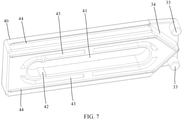
- the first sliding portion includes a sliding groove 31, which is extended obliquely upward along the direction in which the stopper 40 slides out of the mounting position.
- the second sliding portion includes a sliding protrusion 33, and the sliding protrusion 33 is slidably installed in the sliding groove 31.
- the sliding groove 31 is defined on the pressing block 50 and the sliding protrusion 33 is provided on the stopper 40, so that the sliding protrusion is always located in the sliding groove 31. That is, when either of the stopper 40 and the pressing block 50 is operated, the other can be linked to move, and the connection reliability between the stopper 40 and the pressing block 50 can be ensured.
- a sliding groove 31 is provided on the pressing block 50 corresponding to each of the stoppers 40.
- the second sliding portion includes two sliding protrusions 33, and the two sliding protrusions 33 are provided on the same side of the stopper 40 and distributed at intervals in the up and down direction.
- a center line is defined on each stopper 40, and the center line extends in the sliding direction of the stopper 40 and passes through center points between an upper surface and a lower surface of the stopper 40.
- the positions of the two sliding projections 33 on the stopper 40 are symmetrically arranged with the center line as a symmetrical line.
- the first sliding portion has a first surface 32 facing downward
- the second sliding portion has a second surface 34 facing the first surface 32.
- At least one of the first surface 32 and the second surface 34 is extended obliquely upwardly in the direction in which the stopper 40 slides out of the mounting position.
- the first surface 32 and the second surface 34 are in contact with each other and can slide relative to each other when the stopper 40 is in contact with the pressing block 50.
- the structures of the two stoppers 40 can be the same, so that the two stoppers 40 are actually made of the same material, thereby reducing types of materials used and the cost.
- the first sliding portion has two first surfaces 32 facing downward, a distance between the two first surfaces 32 gradually increases in an upward direction.
- the second sliding portion has two second surfaces 34, a distance between the two second surfaces 34 gradually increases in the direction in which the stopper 40 slides out of the mounting position.
- the positions of the two second surfaces 34 on the stopper 40 are arranged symmetrically with the center line as the symmetrical line.
- the first sliding portion includes a sliding groove 31 and a first surface 32 provided below the sliding groove 31, and the second sliding portion includes a sliding protrusion 33 and a second surface 34.
- the position limiting structure further includes a shield 60.
- the shield 60 covers the mounting position, and the stopper 40 and the pressing block 50 are located between the shield 60 and the inner wall of the water tank 10.
- the shield 60 is plate shaped and connected to the water tank 10, and an upper end of the shield 60 is not higher than the upper end of the support protrusion 12, so that the bottom of the machine body 20 can abut against the upper end of the support protrusion 12.
- the linkage structure between the stopper 40 and the pressing block 50 can be prevented from being exposed to outside, and foreign objects can be prevented from touching the linkage structure or sundries can be prevented from entering the linkage structure, thus playing a better protective role on the linkage structure, and ensuring the linkage reliability of the stopper 40 and the pressing block 50.
- the shield 60 may be in a grid structure or the like, or be omitted.
- a first guide structure is provided between the shield 60 and the stopper 40, and the first guide structure is configured to restrict the stopper 40 from moving up and down.
- the first guide structure is extended along the sliding direction of the stopper 40 to ensure that the stopper 40 can slide smoothly between the inner wall of the water tank 10 and the shield 60. Since the first guide structure is disposed between the shield 60 and the stopper 40, there is no need to provide a guide structure on the inner wall of the water tank 10, thereby simplifying the structure of the water tank 10.
- the first guide structure may be provided between the water tank 10 and the stopper 40.
- the first guide structure may be one of various configurations.
- the first guide structure includes a first guide groove 61 defined on the shield 60.
- the first guide groove 61 is extended in the transverse direction and has a first exiting opening 62.
- the stopper 40 is slidably installed in the first guide groove 61 and can be protruded out from the first exiting opening 62.
- the first guide groove 61 is extended in the sliding direction of the stopper 40, and the first exiting opening 62 is located at one end of the first guide groove 61 away from the pressing block 50.
- the stopper 40 is wholly and slidably installed in the first guide groove 61 as a whole, that is, a lower side portion of the stopper 40 slides relative to a lower side wall of the first sliding groove, and an upper side portion of the stopper 40 is slidably connected with an upper side wall of the first sliding groove.
- a structural strength of the first guide structure is high, and the movement reliability of the stopper 40 can be guaranteed to be good.
- the stopper 40 may be partially and slidably installed in the first guide groove 61.
- the first guide groove 61 may be defined on the stopper 40.
- the first guide structure includes a protrusion provided on the shield 60, and the protrusion can protrude from the first guide groove 61.
- the first guide structure includes a first guide hole 41 defined on the stopper 40 and a first guide post 63 provided on the shield 60.
- the first guide hole 41 is extended in the transverse direction in a long strip shape, and the first guide post 63 is slidably installed in the first guide hole 41.
- the first guide hole 41 is extended in the sliding direction of the stopper 40 in a long strip shape, and both ends of the first guide hole 41 are closed, so that the first guide post 63 can always be located in the first guide hole 41. That is, the stopper 40 can be guided to slide, and the stopper 40 can be prevented from being separated from the shield 60, so that the overall reliability of the position limiting structure is high.
- a number of first guide posts 63 may be one or more.
- the plurality of first guide posts 63 are distributed at intervals in the sliding direction of the stopper 40.
- the first guide hole 41 may be defined on the shield 60 and the first guide post 63 may be provided on the stopper 40.
- the first guide structure may include the first guide groove 61, the first guide post 63 provided in the first guide groove 61, and the first guide hole 41 defined on the stopper 40.
- the first guide post 63 is provided with a first limiting protrusion 631.
- the first limiting protrusion 631 is located at a free end of the first guide post 63 and protruded toward a lateral direction of the first guide post 63.
- the stopper 40 is slidably installed between the first limiting protrusion 631 and the shield 60.
- each of two opposite sides of the free end of the first guide post 63 is provided with one first limiting protrusion 631.
- Two first limiting protrusions 631 are distributed along a width direction of the first guide hole 41.
- a protrusion height of the first limiting protrusion 631 relative to a side surface of the first guide post 63 is greater than a gap between the first guide post 63 and the first guide hole 41, and a distance between the first limiting protrusion 631 and a root portion of the first guide post 63 is greater than a depth of the first guide hole 41.
- the stopper 40 When assembling the position limiting structure, the stopper 40 can be installed on the shield 60 first, and then the shield 60 and the stopper 40 can be installed on the inner wall of the water tank 10 together, and the situation that the stopper 40 and the shield 60 are separated from each other during the mounting process can be avoided, thereby facilitating the assembly of the position limiting structure.
- the stopper 40 is defined with first material reduction holes 43, and the first material reduction holes 43 are defined at intervals outside the first guide hole 41 and extended along an extension direction of the first guide hole 41. That is, each first material reduction hole 43 has a long strip shape.
- the wall of the first guide hole 41 can be elastically deformed toward the first material reduction holes 43, so that an abutting force between the first limiting protrusion 631 and the wall of the first guide hole 41 can be reduced, the force required for the assembly can be reduced, and the first limiting protrusion 631 can be easily passed through the first guide hole 41 to facilitate assembly of the position limiting structure.
- the number of the first material reduction holes 43 may be one or more.
- the plurality of first material reduction holes 43 are distributed at intervals along the extension direction of the first guide hole 41, so that a length of each first material reduction hole 43 can be reduced, which ensures that the wall of the first guide hole 41 has sufficient strength, and prevents the wall of the first guide hole 41 from being easily deformed or broken and the first limiting protrusion 631 from easily falling out.
- the first material reduction holes 43 may be omitted.
- the first guide hole 41 is internally provided with a necking portion 42.
- a width of the first guide hole 41 at the necking portion 42 is smaller than a size of the first guide post 63.
- the first guide post 63 is located on a side of the necking portion 42 away from the pressing block 50.
- the necking portion 42 is spaced apart from the ends of the first guide hole 41, and a distance between the necking portion 42 and the first guide hole 41 is larger than a diameter of the first guide post 63, so that the first guide post 63 can pass over the necking portion 42 and be located on the side of the necking portion 42 away from the pressing block 50.
- the stopper 40 is provided with a first material reduction hole 43 corresponding to the necking portion 42, so as to reduce the friction between the necking portion 42 and the first guide post 63 and reduce abrasion when the first guide post 63 passes through the necking portion 42.
- a protrusion may be provided on one side wall of the first guide hole 41 to form the necking portion 42, or protrusions may be provided on both side walls of the first guide hole 41 to form the necking portion 42, or when the first material reduction hole 43 is provided, the side wall of the first guide hole 41 may be raised inward to form the necking portion 42.
- the stopper 40 has at least one first sliding surface, the first sliding surface facing the shield 60 or the inner wall of the water tank 10.
- the first sliding surface is provided with a first sliding rib 44, and the first sliding rib 44 is extended along the sliding direction of the stopper 40.
- the first sliding surface is a surface of the stopper 40 that can contact the shield 60 or the inner wall of the water tank 10.
- a contact area between the stopper 40 and the shield 60 (or the inner wall of the water tank 10) can be reduced by contacting the stopper 40 with the shield 60 (or the inner wall of the water tank 10) through the first sliding rib 44, so that the friction exerted on the stopper 40 during sliding can be reduced when the stopper slides relative to the shield 60 (or the inner wall of the water tank 10), and the sliding effect can be improved.
- a cross section of the first sliding rib 44 may be semicircular, square, or triangular.
- the cross section of the first sliding rib 44 is semicircular, there is only linear contact between the first sliding rib 44 and the shield 60 (or the inner wall of the water tank 10), thereby further reducing friction and friction resistance.
- the stopper 40 may have only one first sliding surface facing the shield 60 or the inner wall of the water tank 10, or may have a plurality of first sliding surfaces.
- the stopper 40 has four first sliding surfaces, one of the four first sliding surfaces faces an upper side wall of the first guide groove 61, one of the four first sliding surfaces faces a lower side wall of the first guide groove 61, one of the four first sliding surfaces faces a groove bottom wall of the first guide groove 61, and one of the four first sliding surfaces faces the inner wall of the water tank 10.
- Each of the first sliding surfaces is provided with a first sliding rib 44.
- the first sliding rib(s) 44 may be provided on parts of the first sliding surfaces.
- a second guide structure is provided between the shield 60 and the pressing block 50, and the second guide structure is configured to restrict the pressing block 50 from moving in the transverse direction.
- the second guide structure is extended along the sliding direction of the pressing block 50 to ensure that the pressing block 50 can slide smoothly between the inner wall of the water tank 10 and the shield 60. Since the second guide structure is disposed between the shield 60 and the pressing block 50, there is no need to provide a guide structure on the inner wall of the water tank 10, thereby simplifying the structure of the water tank 10.
- the second guide structure may be provided between the water tank 10 and the pressing block 50.
- the first guide structure may be one of various configurations.
- the second guide structure includes a second guide groove 64 defined on the shield 60.
- the second guide groove 64 is extended in the up and down direction and has a second exiting opening 641 facing upward.
- the pressing block 50 is slidably installed in the second guide groove 64 and can be protruded out from the second existing opening 641.
- the second guide groove 64 is extended in the sliding direction (i.e., the up and down direction) of the pressing block 50, the second exiting opening 641 is located at an upper end of the second guide groove 64, and the lower end of the second guide groove 64 is extended and penetrated through an upper groove wall of the first guide groove 61.
- the pressing block 50 is wholly and slidably installed within the second guide groove 64. In this way, the structural strength of the second guide structure is high, and the movement reliability of the pressing block 50 can be ensured to be good.
- the pressing block 50 may be partially and slidably installed in the second guide groove 64.
- this application is not limited to this, and the second guide groove 64 may be defined on the pressing block 50.
- the second guide structure includes a protrusion provided on the shield 60, and the protrusion can protrude from the second guide groove 64.
- the second guide structure includes a second guide hole 51 defined on the pressing block 50 and a second guide post 65 provided on the shield 60.
- the second guide hole 51 is extended in the up and down direction to form a long strip shape, and the second guide post 65 is slidably mounted in the second guide hole 51.
- the second guide hole 51 is extended along the sliding direction of the pressing block 50 to form a long strip shape, and both ends of the second guide hole 51 are closed, so that the second guide post 65 can always be located in the second guide hole 51. That is, the pressing block 50 can be guided to slide, and the pressing block 50 can be prevented from being separated from the shield 60, so that the overall reliability of the position limiting structure is high.
- a number of the second guide posts 65 may be one or more.
- the plurality of second guide posts 65 are spaced apart in the sliding direction of the pressing block 50.
- the second guide hole 51 may be defined on the shield 60 and the second guide post 65 may be provided on the pressing block 50.
- the second guide structure may include a second guide groove 64, the second guide post 65 provided in the second guide groove 64, and the second guide hole 51 defined on the stopper 40.
- the second guide hole 51 is defined from one side of the pressing block 50 toward a direction close to the other opposite side. That is, the second guide hole 51 is offset from a midpoint position of the two opposite sides of the pressing block 50.
- the second guide post 65 is provided on a groove bottom wall of the second guide groove 64, and the second guide post 65 is provided corresponding to the second guide hole 51. That is, the second guide post 65 is also offset from a midpoint position of two groove side walls of the second guide groove 64. In this way, it can ensure that both the pressing block 50 and the shield 60 have unique installation states, and it can prevent the pressing block 50 from being installed in reverse.
- the second guide hole 51 can be provided at the midpoint position of the two opposite sides of the pressing block 50.
- the second guide post 65 is provided with a second limiting protrusion 651.
- the second limiting protrusion 651 is located at a free end of the second guide post 65 and protruded toward a lateral direction of the second guide post 65.
- the pressing block 50 is slidably installed between the second limiting protrusion 651 and the shield 60.
- each of two opposite sides of the free end of the second guide post 65 is provided with one second limiting protrusion 651.
- Two second limiting projections 651 are distributed along a width direction of the second guide hole 51.
- a protrusion height of the second limiting protrusion 651 relative to a side surface of the second guide post 65 is greater than a gap between the second guide post 65 and the second guide hole 51, and a distance between the second limiting protrusion 651 and a root portion of the second guide post 65 is greater than a depth of the second guide hole 51.
- the pressing block 50 When assembling the position limiting structure, the pressing block 50 can be installed on the shield 60 first, and then the shield 60 and the pressing block 50 can be installed on the inner wall of the water tank 10 together, and the situation that the pressing block 50 and the shield 60 are separated from each other during the installation process can be avoided, thereby facilitating the assembly of the position limiting structure.
- the pressing block 50 is defined with second material reduction holes 52, and the second material reduction holes 52 are defined at intervals outside the second guide hole 51 and extended along an extension direction of the second guide hole 51. That is, each second material reduction hole 52 has a long strip shape.
- the wall of the second guide hole 51 can be elastically deformed toward the second material reduction holes 52, so that an abutting force between the second limiting protrusion 651 and the wall of the second guide hole 51 can be reduced, the force required for assembly can be reduced, and the second limiting protrusion 651 can be easily passed through the second guide hole 51 to facilitate assembly of the position limiting structure.
- the number of the second material reduction holes 52 may be one or more.
- the plurality of second material reduction holes 52 are distributed at intervals along the extension direction of the second guide hole 51, so that a length of each second material reduction holes 52 can be reduced, which ensures that the wall of the second guide hole 51 has sufficient strength, and prevents the wall of the second guide hole 51 from being easily deformed or broken and the second limiting protrusion 651 from easily falling out.
- the second material reduction holes 52 may be omitted.
- the pressing block 50 has at least one second sliding surface, the second sliding surface facing the shield 60 or the inner wall of the water tank 10.
- the second sliding surface is provided with a second sliding rib 53, and the second sliding rib 53 is extended along the sliding direction of the pressing block 50.
- the second sliding surface is a surface of the pressing block 50 that can contact the shield 60 or the inner wall of the water tank 10.
- a cross-section of the second sliding rib 53 may be semicircular, square, or triangular.
- the cross-section of the second sliding rib 53 is semicircular, there is only linear contact between the second sliding rib 53 and the shield 60 (or the inner wall of the water tank 10), thereby further reducing friction and frictional resistance.
- the stopper 40 may have only one second sliding surface facing the shield 60 or the inner wall of the water tank 10, or have a plurality of second sliding surfaces.
- the pressing block 50 has four second sliding surfaces, one of the four second sliding surfaces faces an upper side wall of the second guide groove 64, one of the four second sliding surfaces faces a lower side wall of the second guide groove 64, one of the four second sliding surfaces faces a groove bottom wall of the second guide groove 64, and one of the four second sliding surfaces faces the inner wall of the water tank 10.
- Each of the second sliding surfaces is provided with a second sliding rib 53.
- the second sliding rib(s) 53 may be provided on parts of the second sliding surfaces.
- a snapping structure is provided between the pressing block 50 and the shield 60. At the first position, the pressing block 50 is clamped with the shield 60. In this way, the stopper 40 can be restricted from switching from the first position to the second position, that is, the stopper 40 can be prevented from automatically switching to the second position before the user discharges the dehumidification water in the water tank 10.
- the snapping structure can be one of various configurations.
- the pressing block 50 is provided with an elastic buckle 54, and a surface of the shield 60 facing the mounting position is defined with a stop hole 66.
- the stop hole 66 is extended through a surface of the shield 60 facing away from the mounting position.
- the elastic buckle 54 is snapped in the stop hole 66. That is, the elastic buckle 54 and the stop hole 66 constitute the snapping structure, in other words, the snapping structure includes the elastic buckle 54 and the stop hole 66.
- the elastic buckle 54 can engage in the stop hole 66, thereby restricting the upward movement of the pressing block 50.
- the elastic buckle 54 located in the stop hole 66 can be pressed to make the elastic buckle 54 out of the stop hole 66.
- the pressing block 50 is no longer restricted by the stop hole 66 and can move upward, that is, the stopper 40 can be switched from the first position to the second position.
- the elastic buckle 54 may be provided on the shield 60, and the stop hole 66 may be defined on the pressing block 50.
- each of the shield 60 and the pressing block 50 is provided with an elastic buckle 54, and the shield 60 and the pressing block 50 are engaged with each other by elastic buckles 54.
- the surface of the shield 60 facing the mounting position is provided with an avoidance slot 67 extending in the up and down direction, and the avoidance slot 67 is above the stop hole 66 and spaced from the stop hole 66.
- the elastic buckle 54 is located in the avoidance slot 67. Specifically, when the pressing block 50 moves upward, the elastic buckle 54 comes out of the stop hole 66 and passes over a spacing between the stop hole 66 and the avoidance slot 67, and the elastic buckle 54 then can enter the avoidance slot 67.
- the elastic buckle 54 is spaced apart from a groove bottom of the avoidance slot 67, that is, when the elastic buckle 54 is located in the avoidance slot 67, the elastic buckle 54 is in a free state and does not contact the shield 60. In this way, permanent deformation of the elastic buckle 54 caused by being pressed for a long time can be avoided, and the service life of the elastic buckle 54 can be prolonged.
- the elastic buckle 54 is slid out from the avoidance slot 67, during the movement before the elastic buckle 54 engages in the stop hole 66, the elastic buckle 54 is pressed by the shield 60 and elastically deforms.
- a distance between the avoidance slot 67 and the stop hole 66 can be reduced, thereby reducing a time duration of the elastic buckle 54 being pressed, and reducing the friction between the elastic buckle 54 and the shield 60 when moving from the avoidance slot 67 to the stop hole 66, and facilitating the prolonging of the service life of the elastic buckle 54.
- a lower side wall of the avoidance slot 67 is disposed inclined downward to provide guidance for the elastic buckle 54 to slide to the avoidance slot 67.
- the support protrusion 12 includes an upper support plate 121 and a lower support plate 122 below the upper support plate 121 and spaced from the upper support plate 121, the mounting position is formed between the upper support plate 121 and the lower support plate 122. Both the upper support plate 121 and the lower support plate 122 are extended transversely.
- the upper support plate 121 has a fracture, and the pressing block 50 (refer to FIG. 4 ) is extended upward from the fracture.
- the pressing block 50 can be arranged closer to the inner wall of the water tank 10, so that an overall protrusion height of the supporting protrusion 12 and the position limiting structure relative to the inner wall of the water tank 10 can be reduced, thereby facilitating the reduction of the depth of the avoidance groove 21 on the machine body 20, and increasing an inner space of the machine body 20.
- the shield 60 is provided between the upper support plate 121 and the lower support plate 122, and a lower side portion of the shield 60 can be brought into abutting against an upper plate surface of the lower support plate 122, so that the shield 60 can be supported by the lower support plate 122.
- An upper side portion of the shield 60 can be brought into abutting against a lower plate surface of the upper support plate 121, so that the upper support plate 121 can be supported by the lower support plate 122, and a supporting capacity of the support protrusion 12 can be improved.
- the support protrusion 12 further includes a first reinforcing rib 123.
- the first reinforcing rib 123 is connected to the lower plate surface of the upper support plate 121, and the shield 60 is provided with an avoidance position corresponding to the first reinforcing rib 123.
- a lower surface of the first reinforcing rib 123 may be brought into abutting against a surface facing upward at the avoidance position, so that a supporting area between the shield 60 and the supporting protrusion 12 can be increased.
- the first reinforcing ribs 123 may be one of various configurations, for example, the first reinforcing rib 123 may be a criss-crossing grid structure, or the first reinforcing rib 123 may be a vertical rib extending in the up and down direction.
- the support protrusion 12 further includes a second reinforcing rib 124, and the first reinforcing rib 123 is connected to the lower support plate 122.
- the first reinforcing rib 123 may be connected to an upper plate surface of the lower support plate 122.
- the shield 60 may also be provided with an avoidance position corresponding to the second reinforcing rib 124, and an upper surface of the first reinforcing rib 123 may be brought into abutting against a surface facing downward at the avoidance position, so that a support area between the shield 60 and the support protrusion 12 can be increased.
- the first reinforcing rib 123 may be connected to a lower plate surface of the lower support plate 122.
- the second reinforcing rib 124 may be one of various configurations, for example, the second reinforcing rib 124 may be a criss-crossing grid structure, or the second reinforcing rib 124 may be a vertical rib extending in the up and down direction.
- the support protrusion 12 further includes a support rib, an upper end of the support rib is connected to the lower support plate 122, a lower end of the support rib is extended toward the bottom wall of the water tank 10, and the lower end of the support rib is connected to or spaced from the bottom wall of the water tank 10.
- the shield 60 is detachably connected to the support protrusion 12 to facilitate the assembly of the position limiting structure. In this way, when the pressing block 50, the shield 60, or the stopper 40 is damaged or worn, it can be easily replaced. Since the entire water tank 10 does not need to be replaced, the cost can be reduced.
- the shield 60 is engaged with the support projection 12, which is convenient to assemble, and does not need to be screwed, the production efficiency is improved. Specifically, both ends of the shield 60 along the sliding direction of the stopper 40 are provided with buckle holes 68, and the first reinforcing rib 123 is provided with a buckle 125 corresponding to each buckle hole 68.
- the buckle 125 is protruded along the sliding direction of the stopper 40.
- the shield 60 are engaged with the support protrusion 12 through the buckle 125 and the buckle holes 68.
- the buckle holes 68 are provided above and below the stopper 40 to ensure the connection reliability between the shield 60 and the supporting protrusion 12.
- the shield 60 and the support protrusion 12 may also be connected by screws or the like.
Landscapes
- Engineering & Computer Science (AREA)
- Chemical & Material Sciences (AREA)
- Combustion & Propulsion (AREA)
- Mechanical Engineering (AREA)
- General Engineering & Computer Science (AREA)
- Air Humidification (AREA)
- Drying Of Gases (AREA)
- Devices For Blowing Cold Air, Devices For Blowing Warm Air, And Means For Preventing Water Condensation In Air Conditioning Units (AREA)
Abstract
Description
- This application claims the priority of Chinese patent applications filed in the China Patent Office on
August 6, 2020 with application numbers 202010786623.1 202021623960.0 - This application relates to the technical field of air dehumidification, in particular to a dehumidifier.
- In some dehumidifiers, the water tanks are arranged outside the machine bodies. When the dehumidifiers work, the machine bodies are placed above the water tanks. After the work is done, the dehumidification water in the water tanks needs to be completely discharged and then the machine bodies are stored in the water tanks. However, in actual use, after the work is done, the users are prone to forget to discharge the water in the water tanks, and directly put the machine bodies in the water tanks with dehumidification water, thus causing water inflow to the machine bodies and damaging the machine bodies.
- The main purpose of this application is to provide a dehumidifier, which aims to reduce the possibility that a user mistakenly puts the machine body into the water tank and causes water inflow to the machine body and damage the machine body when there is water in the water tank.
- To achieve the above purpose, this application provides a dehumidifier including:
- a water tank with a mounting opening facing upward;
- a machine body having an idle state, the machine body being at least partially accommodated in the water tank through the mounting opening in the idle state; and
- a position limiting structure including a stopper, the stopper being movable into and out of the mounting opening and having a first position and a second position, the stopper being entered in the mounting opening and located on a movement path of the machine body moving toward the water tank at the first position, and the stopper being exited out of the mounting opening for the machine body to be accommodated in the water tank at the second position.
- In one embodiment, the machine body further has a working state, the machine body is raised relative to the water tank through the mounting opening in the working state.
- In one embodiment, an inner wall of the water tank is formed with a support protrusion, and a side of the machine body is defined with an avoidance groove, and the avoidance groove is extended and penetrated through a bottom of the machine body, the support protrusion is extended into the avoidance groove in the idle state, and the bottom of the machine body is supported by an upper end of the support protrusion in the working state.
- In one embodiment, a mounting position is arranged below the support protrusion, the stopper is slidably installed at the mounting position, a sliding direction of the stopper is along a transverse direction, at the first position, the stopper is extended laterally toward the support protrusion to restrict the machine body from moving toward the water tank, and at the second position, the stopper is retracted to the mounting position for the machine body to be accommodated in the water tank.
- In one embodiment, the position limiting structure further includes a pressing block slidably installed on the water tank, and a sliding direction of the pressing block is along an up and down direction, a linkage structure is arranged between the pressing block and the stopper, thereby when the pressing block is slid downward, the stopper is slid from the second position to the first position.
- In one embodiment, the pressing block is slidably installed at the mounting position, at the second position, an upper end of the pressing block is higher than the upper end of the support protrusion, and at the first position, the upper end of the pressing block is not higher than the upper end of the support protrusion.
- In one embodiment, the linkage structure includes a first sliding portion provided on the pressing block and a second sliding portion provided on the stopper, at least one of the first sliding portion and the second sliding portion is extended obliquely upward in a direction in which the stopper slides out of the mounting position.
- In one embodiment, the first sliding portion defines a sliding groove extending obliquely upward in the direction in which the stopper slides out of the mounting position, and the second sliding portion includes a sliding protrusion slidably installed in the sliding groove; and/or,
the first sliding portion has a first surface facing downward and the second sliding portion has a second surface facing the first surface, at least one of the first surface and the second surface is extended obliquely upward in the direction in which the stopper slides out of the mounting position. - In one embodiment, the position limiting structure further includes a shield covering the mounting position, and the stopper and the pressing block are located between the shield and the inner wall of the water tank.
- In one embodiment, a first guide structure is provided between the shield and the stopper, and configured to restrict a movement of the stopper in the up and down direction.
- In one embodiment, the first guide structure includes a first guide groove defined on the shield, extended transversally and having a first exiting opening, the stop member is slidably installed in the first guide groove and capable of being protruded from the first exiting opening.
- In one embodiment, the first guide structure includes a first guide hole defined on the stopper and a first guide post provided on the shield, the first guide hole is extended transversally in a long strip shape, and the first guide post is slidably installed in the first guide hole.
- In one embodiment, the first guide post is provided with a first limiting protrusion located at a free end of the first guide post and protruded toward a lateral direction of the first guide post, the stopper is slidably installed between the first limiting protrusion and the shield.
- In one embodiment, the stopper is defined with first material reduction holes arranged outside the first guide hole at intervals and extended along an extension direction of the first guide hole.
- In one embodiment, the first guide hole is internally provided with a necking portion, a width of the first guide hole at the necking portion is smaller than a size of the first guide post, at the second position, the first guide post is located on a side of the necking portion away from the pressing block.
- In one embodiment, the stopper has at least one first sliding surface facing the shield or the inner wall of the water tank, and the first sliding surface is provided with a first sliding rib extended along the sliding direction of the stopper.
- In one embodiment, a second guide structure is provide between the shield and the pressing block, and configured for restricting a movement of the pressing block in the transverse direction.
- In one embodiment, the second guide structure includes a second guide groove defined on the shield, extended in the up and down direction and having a second existing opening facing upward, the pressing block is slidably installed in the second guide groove and capable of being protruded from the second protruding opening; and/or,
the second guide structure includes a second guide hole defined on the pressing block and a second guide post configured on the shield, the second guide hole is extended along the up and down direction in a long strip shape, and the second guide post is slidably installed in the second guide hole. - In one embodiment, the pressing block is configured with an elastic buckle, a surface of the shield facing the mounting position is defined with a stop hole, the stop hole is extended and penetrated through a surface of the shield facing away from the mounting position, and at the first position, the elastic buckle is snapped in the stop hole.
- In one embodiment, the surface of the shield facing the mounting position is defined with an avoidance slot extended in the up and down direction, the avoidance slot is arranged above the stop hole and spaced from the stop hole, at the second position, the elastic buckle is located in the avoidance slot.
- In one embodiment, the support protrusion includes an upper support plate and a lower support plate arranged below the upper support plate and spaced from the upper support plate, the mounting position is formed between the upper support plate and the lower support plate, both the upper support plate and the lower support plate are extended transversely, the upper support plate has a fracture, and the pressing block is extended upward from the fracture.
- In one embodiment, the shield is detachably connected to the support protrusion
- In the technical scheme of this application, a stopper is arranged movably entering and leaving the mounting opening on the water tank. When the stopper is moved to a first position and being entered in the mounting opening, the stopper can be located on a movement path of the machine body moving toward the water tank, so that when the machine body moves toward the water tank, the stopper can abut against a bottom of the machine body, and the movement of the machine body toward the water tank can be restricted. Therefore, the situation that the machine body directly falls into dehumidification water in the water tank and is damaged can be avoided, that is, the possibility that the machine body is damaged by water inflow caused by a user mistakenly putting the machine body into the water tank when the water tank has dehumidification water is reduced.
- In order to more clearly explain the embodiments of this application or the technical solutions in the related art, the drawings used in the description of the embodiments or the related art will be briefly introduced below. Obviously, the drawings in the following description are merely some embodiments of this application. For those of ordinary skill in the art, other drawings can be obtained based on the structure shown in these drawings without creative work.
-
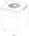
FIG. 1 is a schematic structural view of a dehumidifier according to an embodiment of this application, with a machine body being in an idle state; -
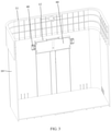
FIG. 2 is a schematic structural view of the machine body and the water tank ofFIG. 1 , with the machine body being in a working state; -
FIG. 3 is a schematic sectional view of the water tank ofFIG. 2 , with a stopper being in a first position; -
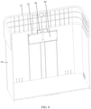
FIG. 4 is a schematic sectional view of the water tank ofFIG. 1 , with the stopper being in a second position; -
FIG. 5 is a structural view of a position limiting structure ofFIG. 3 . -
FIG. 6 is a structural view of the position limiting structure ofFIG. 4 . -
FIG. 7 is a schematic structural view of a stopper ofFIG. 6 . -
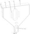
FIG. 8 is a schematic structural view of a pressing block ofFIG. 6 . -
FIG. 9 is a schematic view of the pressing block ofFIG. 8 , viewed from another side. -
FIG. 10 is a schematic structural view of a shield ofFIG. 6 . -
FIG. 11 is a schematic view of the shield ofFIG. 10 , viewed from another side. -
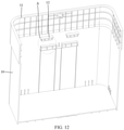
FIG. 12 is a schematic structural view of the water tank ofFIG. 3 . -
FIG. 13 is an enlarged view of portion A ofFIG. 12 . - Description of Labels in the figures:
Label Name Label Name 10 Water tank 44 First sliding rib 11 mounting opening 50 Pressing block 12 Support protrusion 51 Second guide hole 121 Upper support plate 52 Second material reduction hole 122 Lower support plate 53 Second sliding rib 123 First reinforcing rib 54 Elastic buckle 124 Second reinforcing rib 60 Shield 125 Buckle 61 First guide groove 20 machine body 62 First exiting opening 21 Avoidance groove 63 First guide post 31 Sliding groove 631 First limiting protrusion 32 First surface 64 Second guide groove 33 Sliding protrusion 641 Second exiting opening 34 Second surface 65 Second guide post 40 Stopper 651 Second limiting protrusion 41 First guide hole 66 Stop hole 42 Necking portion 67 Avoidance slot 43 First material reduction hole 68 Buckle hole - The realization of the purposes, functional features and advantages of this application will be further explained with reference to the accompanying drawings in combination with the embodiments.
- In the following, the technical solutions in the embodiments of this application will be clearly and completely described with reference to the drawings in the embodiments of this application. Obviously, the described embodiments are only a part of the embodiments of this application, and not all of the embodiments. Based on the embodiments of this application, all other embodiments obtained by those of ordinary skilled in the art without creative efforts shall fall within the claimed scope of this application.
- It should be noted that all directional indicators (such as up, down, left, right, front, back, etc.) in the embodiments of this application are only used to explain the relative positional relationship, movement situation, etc. between components in a specific posture (as shown in the drawings). If the specific posture changes, the directional indication also changes accordingly.
- In addition, the descriptions related to "first", "second", and the like in this application are for descriptive purposes only, and cannot be understood as indicating or implying their relative importance or implicitly indicating the number of technical features indicated. Therefore, a features associated with "first" and "second" may explicitly or implicitly include at least one of such feature. In addition, the meaning of "and/or" in the full text is to include three scenarios. Taking "A and/or B" as an example, it includes A technical solution, B technical solution, and technical solutions that A and B are both met. In addition, the technical solutions of the various embodiments can be combined with each other, but they must be based on what can be achieved by those of ordinary skill in the art. When the combination of technical solutions is contradictory or cannot be achieved, it should be considered that such a combination of technical solutions does not exist, or is not within the scope of protection defined by the claims of this application.
- This application provides a dehumidifier.
- In the embodiment of this application, please refer to
FIGS. 1 to 4 , the dehumidifier includes awater tank 10, amachine body 20 and a position limiting structure. Thewater tank 10 has an upward mountingopening 11, and themachine body 20 has an idle state in which themachine body 20 is at least partially housed in thewater tank 10 through the mountingopening 11. - The position limiting structure includes a
stopper 40, which can move into and out of the mountingopening 11, and has a first position and a second position. In the first position, thestopper 40 is entered in the mountingopening 11 and is located on a movement path of themachine body 20 moving toward inside of thewater tank 10. In the second position, thestopper 40 is exited out of the mountingopening 11 for themachine body 20 to be accommodated in thewater tank 10. - In this embodiment, dehumidification water generated when the
machine body 20 performs dehumidification can enter thewater tank 10. Themachine body 20 and thewater tank 10 are both square in shape, however those are the shapes of themachine body 20 and thewater tank 10 in only one embodiment. In other embodiments, themachine body 20 and thewater tank 10 may be, but are not limited to, circular, polygonal, or even irregular in shape, and themachine body 20 can be at least partially received within thewater tank 10 through the mountingopening 11. - When the
machine body 20 is taken out of thewater tank 10 for dehumidification, thestopper 40 can be moved to the first position where thestopper 40 enters the mounting opening 11 (Thestopper 40 can be switched to the first position when themachine body 20 is taken out of thewater tank 10, or when there is a certain amount of dehumidification water in thewater tank 10 after themachine body 20 has been operated for a certain period of time, or when themachine body 20 is lifted again after themachine body 20 has been operated for a certain period of time). At this time, thestopper 40 is located on the movement path of themachine body 20 moving toward inside of thewater tank 10, so that when themachine body 20 moves toward inside of thewater tank 10, thestopper 40 can abut against a bottom of themachine body 20, and can restrict themachine body 20 from moving toward inside thewater tank 10. When themachine body 20 finishes working and the dehumidification water in thewater tank 10 is discharged or poured out, thestopper 40 is switched to the second position out of the mountingopening 11, so that themachine body 20 can move toward inside thewater tank 10 and be accommodated in thewater tank 10. - In the technical scheme of this application, a
stopper 40 is provided to movably enter and exit a mountingopening 11 on thewater tank 10, when thestopper 40 moves to a first position and being entered in the mountingopening 11, thestopper 40 can be located on a movement path of themachine body 20 moving toward inside of thewater tank 10, so that when themachine body 20 moves toward inside of thewater tank 10, thestopper 40 can abut against a bottom of themachine body 20, and can restrict themachine body 20 from moving toward inside of thewater tank 10. Therefore, it can avoid the case where themachine body 20 falls directly into the dehumidification water in thewater tank 10 and is damaged, that is, it can reduce the case where thewater tank 10 has dehumidification water, and the user mistakenly puts themachine body 20 into thewater tank 10 and causes themachine body 20 to be damaged by water inflow. - By disposing the
water tank 10 outside themachine body 20, a volume of thewater tank 10 is larger, a storage capacity of thewater tank 10 is increased, the number of times a user pours water is reduced, and the weight of themachine body 20 is also reduced which facilitates the user to carry themachine body 20. In addition, when themachine body 20 is in an idle state, themachine body 20 is received in thewater tank 10, the center of gravity of the dehumidifier can be lowered, so that the dehumidifier can be placed stably and is not easy to fall, and an overall occupied space of the dehumidifier is reduced and the user can place the dehumidifier conveniently. - In this embodiment, the
machine body 20 also has a working state, in which themachine body 20 is raised related to thewater tank 10 through the mountingopening 11. Specifically, in the working state, themachine body 20 at least partially protrudes above thewater tank 10, for example, a portion of themachine body 20 provided with an air inlet and an air outlet is located above the water tank to be exposed outside thewater tank 10, which substantially elevates a position of the air outlet of themachine body 20, so that the dehumidified air can be blown to a further position, and it is beneficial to improve a range of indoor air flow. Moreover, the dehumidification water generated by themachine body 20 can naturally fall into thewater tank 10, and it is convenient for collecting the dehumidification water. Of course, in other embodiments, themachine body 20 may be disposed entirely outside thewater tank 10. - In one embodiment, an inner wall of the
water tank 10 is provided with asupport protrusion 12, and a side of themachine body 20 is provided with anavoidance groove 21. Theavoidance groove 21 is extended and penetrated through the bottom of themachine body 20. In the idle state, thesupport protrusion 12 is extended into theavoidance groove 21. In the working state, an upper end of thesupport protrusion 12 supports the bottom of themachine body 20. Specifically, thewater tank 10 is provided outside themachine body 20, thesupport protrusion 12 is provided spaced from a bottom wall of thewater tank 10, and thesupport protrusion 12 is provided spaced from an edge of the mountingopening 11. That is, the upper end of thesupport protrusion 12 is lower than an upper end edge of thewater tank 10, and theavoidance groove 21 extends in a height direction (an up and down direction) of themachine body 20. - When the dehumidifier is used, the
machine body 20 is rotated until theavoidance groove 21 is staggered with the supportingprotrusion 12 of thewater tank 10, so that the bottom of themachine body 20 abuts against the upper end of the supportingprotrusion 12, themachine body 20 is supported by the supportingprotrusion 12 and raised from thewater tank 10. At this time, themachine body 20 is in the working state, and the dehumidification water generated during working of themachine body 20 can be discharged into thewater tank 10. When themachine body 20 finishes working and the water is discharged from thewater tank 10, themachine body 20 is rotated to a state where theavoidance groove 21 faces thesupport protrusion 12, so that thesupport protrusion 12 is extended into theavoidance groove 21, and themachine body 20 is accommodated in thewater tank 10 an stands in the idle state. - Thus, when the upper end of the
support projection 12 supports the bottom of themachine body 20, a portion of themachine body 20 remains within thewater tank 10. Compared with the way that themachine body 20 is completely raised from the inside of thewater tank 10 and placed above thewater tank 10, this arrangement enables the portion of thewater tank 10 above the upper end of the supportingprotrusion 12 to restrict themachine body 20, effectively reduces the turnover of themachine body 20 relative to thewater tank 10, and greatly improves the stability of themachine body 20 in the working state. Thesupport protrusion 12 may be a convex structure integrally formed on an inner wall of thewater tank 10, or may be a support structure movably installed on the inner wall of the water tank 10 (the support structure may refer to a mounting mode of the stopper 40). Of course, in other embodiments, the bottom of themachine body 20 may abut against an upper edge of thewater tank 10. - In one embodiment, a mounting position is provided below the
support protrusion 12, and thestopper 40 is slidably installed at the mounting position. A sliding direction of thestopper 40 is a transverse direction. At the first position, thestopper 40 is extended toward a lateral side of thesupport protrusion 12 to restrict themachine body 20 from moving toward thewater tank 10. At the second position, thestopper 40 is retracted to the mounting position for themachine body 20 to be accommodated in thewater tank 10. - In particular, a lateral direction of the
support projection 12 is the transverse direction (i. e., a horizontal direction). The sliding direction of thestopper 40 may be along a horizontal extension direction of the inner wall of thewater tank 10. At the first position, a length of thestopper 40 protruding from thesupport protrusion 12 is greater than an engagement gap between thesupport protrusion 12 and theavoidance groove 21, that is, a total length of thestopper 40 and thesupport protrusion 12 along the horizontal extension direction of the inner wall of thewater tank 10 is greater than a width of theavoidance groove 21 along the horizontal extension direction of an outer wall of themachine body 20. When the user mistakenly places themachine body 20 in thewater tank 10 in a state where theavoidance groove 21 faces thesupport protrusion 12, a protruding end of thestopper 40 can support the bottom of themachine body 20, thereby restricting themachine body 20 from continuously entering thewater tank 10 downward. - At the second position, the
stopper 40 can be retracted to the mounting position, that is, the length of thestopper 40 protruding relative to thesupport protrusion 12 is smaller than the engagement gap between thesupport protrusion 12 and theavoidance groove 21, or thestopper 40 is entirely retracted into the mounting position, so as to avoid interference between thestopper 40 and themachine body 20 and ensure that themachine body 20 can smoothly enter thewater tank 10. Of course, in other embodiments, the sliding direction of thestopper 40 can be a direction perpendicular to an inner wall surface of thewater tank 10. In addition, in other embodiments, thestopper 40 and thesupport projection 12 can be laterally spaced apart. Further, in other embodiments, thestopper 40 can be rotatably installed on the inner wall of thewater tank 10 to be able to rotate into and out of the mountingopening 11. - By providing a
support protrusion 12 on an inner wall of thewater tank 10, and a position limiting structure at a mounting position below thesupport protrusion 12, astopper 40 of the position limiting structure is slidably installed at the mounting position. When thestopper 40 is slidably protruded toward the lateral side of thesupport protrusion 12, even if the user mistakenly places themachine body 20 on thewater tank 10 in a state where theavoidance groove 21 faces thesupport protrusion 12, thestopper 40 can abut against the bottom of themachine body 20, thereby restricting themachine body 20 from continuing to fall into thewater tank 10. As such, after themachine body 20 is taken out from thewater tank 10, prior to startup of themachine body 20, thestopper 40 can be protruded toward thesupport protrusion 12 to prevent themachine body 20 from being put into thewater tank 10. Even if the user wants to put themachine body 20 into thewater tank 10 after the dehumidifier has been operated for a certain period of time when there is already dehumidification water in thewater tank 10, the stopper can prevent themachine body 20 from falling directly into the dehumidification water in thewater tank 10 and being damaged. It reduces the possibility that when thewater tank 10 has dehumidification water, the user mistakenly puts themachine body 20 into thewater tank 10 and damages themachine body 20 due to water inflow. - In one embodiment, the inner wall of the
water tank 10 is provided with a plurality ofsupport protrusions 12, and the plurality ofsupport protrusions 12 are distributed at intervals along a circumferential direction of thewater tank 10. The outer surface of themachine body 20 is provided with a plurality ofavoidance grooves 21, and the plurality ofavoidance grooves 21 are arranged at intervals along a circumferential direction of themachine body 20. Specifically, eachsupport protrusion 12 corresponds to at least oneavoidance groove 21 that is to engage with thesupport protrusion 12, that is, the number ofavoidance grooves 21 can be larger than the number ofsupport protrusions 12, and eachsupport protrusion 12 is engaged with at least oneavoidance groove 21 to ensure that themachine body 20 can be accommodated in thewater tank 10. - As is understandable, the plurality of
support protrusions 12 are arranged at intervals in the circumferential direction of thewater tank 10. When themachine body 20 needs to be switched from a restricted state to the working state, themachine body 20 can be lifted out of thewater tank 10, and rotated for a certain angle relative to thewater tank 10, so that the plurality ofavoidance grooves 21 and the plurality ofsupport protrusions 12 are dislocated with each other, and the upper end of thesupport protrusions 12 can support the portion of the bottom of themachine body 20 without theavoidance grooves 21. As such, the bottom of themachine body 20 is jointly supported by the plurality ofsupport protrusions 12, so that a plurality of positions in the circumferential direction of themachine body 20 can be supported, and the stability of themachine body 20 in the working state is improved. When a plurality ofsupport protrusions 12 are provided, thestopper 40 orstoppers 40 may be provided below only one or part of the support protrusions 12, or thestoppers 40 may be provided below each of thesupport protrusions 12. - The plurality of
support protrusions 12 can be evenly arranged along the circumferential direction of thewater tank 10, so as to ensure that when the bottom of themachine body 20 abuts against the plurality ofsupport protrusions 12, the force applied on themachine body 20 in the circumferential direction is consistent, which is beneficial to improve the stability of themachine body 20 in the working state. For example, when the number of the supportingprotrusions 12 is two, the two supportingprotrusions 12 are provided on two opposite sides of thewater tank 10, or the like. Of course, in other embodiments, when the number ofsupport protrusions 12 is greater than or equal to three, the plurality ofsupport protrusions 12 may be non-uniformly arranged along the circumferential direction of thewater tank 10. In addition, themachine body 20 may be cylindrical, elliptical or prismatic, and the shape of thewater tank 10 is adapted to the shape of themachine body 20. When themachine body 20 is prismatic, the water tank may be square, regular pentagonal, regular hexagonal, or the like. - In addition, each mounting position can be provided with one or
more stoppers 40, and the sliding directions of the plurality ofstoppers 40 are in the transverse direction. For example, in an embodiment, each mounting position is provided with twostoppers 40, and the twostoppers 40 are slid out of the mounting position in opposite directions. As such, when thestoppers 40 support the bottom of themachine body 20, themachine body 20 is supported by a plurality ofstoppers 40 together, thereby ensuring the stability of themachine body 20 and reducing the possibility of inclination of themachine body 20. - In order to reduce the user's operation and facilitate the user to use the dehumidifier, please refer to
FIGS. 4 to 6 . In an embodiment, the position limiting structure further includes apressing block 50. Thepressing block 50 is slidably installed on thewater tank 10, and a sliding direction of thepressing block 50 is the up and down direction. A linkage structure is provided between thepressing block 50 and thestopper 40, so that when thepressing block 50 slides downward, thestopper 40 slides from the second position to the first position. Thepressing block 50 may be disposed outside thewater tank 10 or inside thewater tank 10. If thepressing block 50 is disposed inside thewater tank 10, an upper end of thepressing block 50 can be protruded outward from the mountingopening 11 for the user to operate. Alternatively, thepressing block 50 may be pressed down by the bottom of themachine body 20 abutting against the upper end of thepressing block 50, to drive thestopper 40 to slide from the second position toward the first position. By providing thepressing block 50, the driving of thestopper 40 can be facilitated, and the operation of the user can be facilitated. - In this embodiment, the
pressing block 50 is slidably installed at the mounting position. At the second position, the upper end of thepressing block 50 is higher than the upper end of thesupport protrusion 12. At the first position, the upper end of thepressing block 50 is not higher than the upper end of thesupport protrusion 12. Specifically, when themachine body 20 is in the idle state, thestopper 40 is at the second position. At this time, thestopper 40 is raised upward through the linkage structure, so that the upper end of thepressing block 50 is higher than the upper end of thesupport protrusion 12. When themachine body 20 is switched to the working state, before the bottom of themachine body 20 is placed on the upper end of the supportingprotrusion 12, themachine body 20 first abuts against the upper end of thepressing block 50, thereby pressing thepressing block 50 down until the bottom of themachine body 20 abuts against the upper end of the supportingprotrusion 12. During the pressing down of thepressing block 50, thepressing block 50 drives thestopper 40 through the linkage structure to protrude laterally toward thesupport projection 12 and move to the first position. In this way, when the user puts themachine body 20 in the working state, thestopper 40 can be automatically switched to the first position, and the user does not need to manually operate thestopper 40, thus greatly facilitating the user's use. - After the dehumidifier finishes working, since the
stopper 40 is in the first position, it is needed to retract thestopper 40 before themachine body 20 can be put into thewater tank 10. In one embodiment, the user manually switches thestopper 40 from the first position to the second position, so that when the user manually operates thestopper 40, the user will find whether there is dehumidification water in thewater tank 10, thereby avoiding the user directly putting themachine body 20 into thewater tank 10 when the user does not find that there is dehumidification water in thewater tank 10, resulting in inflow of water and damage to themachine body 20. Of course, in other embodiments, it can be the situation of manually driving thestopper 40 from the mounting position to the first position by the user without providing thepressing block 50. Alternatively, a motor can be provided at the mounting position, and thestopper 40 is driven by the motor to switch between the first position and the second position. - The linkage structure may be one of various of types. For example, in one embodiment, the linkage structure includes a first sliding portion provided on the
pressing block 50 and a second sliding portion provided on thestopper 40. At least one of the first sliding portion and the second sliding portion is extended obliquely upward along the direction in which thestopper 40 slides out of the mounting position. That is, there may be the first sliding portion or the second sliding portion extending gradually obliquely upward in the direction in which thestopper 40 slides out of the mounting position in a long strip shape. Alternatively, there may be both the first sliding portion and the second sliding portion extending gradually obliquely upward along the direction in which thestopper 40 slides out of the mounting position to form long strip shapes. - When the
pressing block 50 moves downward, the second sliding portion abuts against the first sliding portion and slides relative to the first sliding portion (along an extension direction of the first sliding portion or the second sliding portion), thereby driving thestopper 40 to move in the direction of sliding out of the mounting position to move to the first position. When thestopper 40 is switched from the first position to the second position, the first sliding portion abuts against the second sliding portion and can slide relative to the second sliding portion (along the extension direction of the first sliding portion or the second sliding portion), thereby driving thepressing block 50 to move upward until thestopper 40 moves to the second position. As such, the linkage structure is formed between thepressing block 50 and thestopper 40, the structure is simple, and no additional part is needed, the material is reduced, and the assembly efficiency is improved and the cost is reduced. Of course in other embodiments, the linkage structure may include a link, a first hinge portion provide at thestopper 40, and a second hinge portion provided at thepressing block 50, one end of the link is hinged with the first hinge portion and the other end of the link is hinged with the second hinge portion. - Referring to
FIGS. 7 and8 , the structure of the first sliding portion may be one of various. For example, in one embodiment, the first sliding portion includes a slidinggroove 31, which is extended obliquely upward along the direction in which thestopper 40 slides out of the mounting position. The second sliding portion includes a slidingprotrusion 33, and the slidingprotrusion 33 is slidably installed in the slidinggroove 31. The slidinggroove 31 is defined on thepressing block 50 and the slidingprotrusion 33 is provided on thestopper 40, so that the sliding protrusion is always located in the slidinggroove 31. That is, when either of thestopper 40 and thepressing block 50 is operated, the other can be linked to move, and the connection reliability between thestopper 40 and thepressing block 50 can be ensured. - When two
stoppers 40 are provided in the mounting position (seeFIGS. 5 and 6 ), the structures of the twostoppers 40 can be the same, so that the twostoppers 40 are actually made of the same material, thereby reducing types of materials used and the cost. A slidinggroove 31 is provided on thepressing block 50 corresponding to each of thestoppers 40. In one embodiment, the second sliding portion includes two slidingprotrusions 33, and the two slidingprotrusions 33 are provided on the same side of thestopper 40 and distributed at intervals in the up and down direction. For ease of illustration, a center line is defined on eachstopper 40, and the center line extends in the sliding direction of thestopper 40 and passes through center points between an upper surface and a lower surface of thestopper 40. The positions of the two slidingprojections 33 on thestopper 40 are symmetrically arranged with the center line as a symmetrical line. - In addition, in one embodiment, the first sliding portion has a
first surface 32 facing downward, and the second sliding portion has asecond surface 34 facing thefirst surface 32. At least one of thefirst surface 32 and thesecond surface 34 is extended obliquely upwardly in the direction in which thestopper 40 slides out of the mounting position. Thefirst surface 32 and thesecond surface 34 are in contact with each other and can slide relative to each other when thestopper 40 is in contact with thepressing block 50. Thus, the structure is simple, and structural strengths of the first sliding portion and the second sliding portion can be guaranteed, which is beneficial to improving the linkage reliability of thestopper 40 and thepressing block 50. - When two
stoppers 40 are arranged at the mounting position, the structures of the twostoppers 40 can be the same, so that the twostoppers 40 are actually made of the same material, thereby reducing types of materials used and the cost. In one embodiment, the first sliding portion has twofirst surfaces 32 facing downward, a distance between the twofirst surfaces 32 gradually increases in an upward direction. The second sliding portion has twosecond surfaces 34, a distance between the twosecond surfaces 34 gradually increases in the direction in which thestopper 40 slides out of the mounting position. The positions of the twosecond surfaces 34 on thestopper 40 are arranged symmetrically with the center line as the symmetrical line. - In addition, in an embodiment, the first sliding portion includes a sliding
groove 31 and afirst surface 32 provided below the slidinggroove 31, and the second sliding portion includes a slidingprotrusion 33 and asecond surface 34. - Referring to
FIGS. 1 to 4 , in order to ensure a movement effect of thestopper 40 and thepressing block 50, in one embodiment, the position limiting structure further includes ashield 60. Theshield 60 covers the mounting position, and thestopper 40 and thepressing block 50 are located between theshield 60 and the inner wall of thewater tank 10. Specifically, theshield 60 is plate shaped and connected to thewater tank 10, and an upper end of theshield 60 is not higher than the upper end of thesupport protrusion 12, so that the bottom of themachine body 20 can abut against the upper end of thesupport protrusion 12. By covering theshield 60 at the mounting position, the linkage structure between thestopper 40 and thepressing block 50 can be prevented from being exposed to outside, and foreign objects can be prevented from touching the linkage structure or sundries can be prevented from entering the linkage structure, thus playing a better protective role on the linkage structure, and ensuring the linkage reliability of thestopper 40 and thepressing block 50. Of course, in other embodiments, theshield 60 may be in a grid structure or the like, or be omitted. - In one embodiment, a first guide structure is provided between the
shield 60 and thestopper 40, and the first guide structure is configured to restrict thestopper 40 from moving up and down. Specifically, the first guide structure is extended along the sliding direction of thestopper 40 to ensure that thestopper 40 can slide smoothly between the inner wall of thewater tank 10 and theshield 60. Since the first guide structure is disposed between theshield 60 and thestopper 40, there is no need to provide a guide structure on the inner wall of thewater tank 10, thereby simplifying the structure of thewater tank 10. Of course, in other embodiments, the first guide structure may be provided between thewater tank 10 and thestopper 40. - Referring to
FIGS. 7 and10 , the first guide structure may be one of various configurations. For example, in one embodiment, the first guide structure includes afirst guide groove 61 defined on theshield 60. Thefirst guide groove 61 is extended in the transverse direction and has a first exitingopening 62. Thestopper 40 is slidably installed in thefirst guide groove 61 and can be protruded out from the first exitingopening 62. Specifically, thefirst guide groove 61 is extended in the sliding direction of thestopper 40, and the first exitingopening 62 is located at one end of thefirst guide groove 61 away from thepressing block 50. In one embodiment, thestopper 40 is wholly and slidably installed in thefirst guide groove 61 as a whole, that is, a lower side portion of thestopper 40 slides relative to a lower side wall of the first sliding groove, and an upper side portion of thestopper 40 is slidably connected with an upper side wall of the first sliding groove. In this way, a structural strength of the first guide structure is high, and the movement reliability of thestopper 40 can be guaranteed to be good. Of course, thestopper 40 may be partially and slidably installed in thefirst guide groove 61. Of course, this application is not limited to this, thefirst guide groove 61 may be defined on thestopper 40. The first guide structure includes a protrusion provided on theshield 60, and the protrusion can protrude from thefirst guide groove 61. - In addition, in an embodiment, the first guide structure includes a
first guide hole 41 defined on thestopper 40 and afirst guide post 63 provided on theshield 60. Thefirst guide hole 41 is extended in the transverse direction in a long strip shape, and thefirst guide post 63 is slidably installed in thefirst guide hole 41. In particular, thefirst guide hole 41 is extended in the sliding direction of thestopper 40 in a long strip shape, and both ends of thefirst guide hole 41 are closed, so that thefirst guide post 63 can always be located in thefirst guide hole 41. That is, thestopper 40 can be guided to slide, and thestopper 40 can be prevented from being separated from theshield 60, so that the overall reliability of the position limiting structure is high. A number of first guide posts 63 may be one or more. When the number of the first guide posts 63 is more than one, the plurality of first guide posts 63 are distributed at intervals in the sliding direction of thestopper 40. Of course, this application is not limited to this, thefirst guide hole 41 may be defined on theshield 60 and thefirst guide post 63 may be provided on thestopper 40. In addition, in one embodiment, the first guide structure may include thefirst guide groove 61, thefirst guide post 63 provided in thefirst guide groove 61, and thefirst guide hole 41 defined on thestopper 40. - Referring to
FIGS. 5, 6 and10 , in order to facilitate the assembly of the position limiting structure, in one embodiment, thefirst guide post 63 is provided with a first limitingprotrusion 631. The first limitingprotrusion 631 is located at a free end of thefirst guide post 63 and protruded toward a lateral direction of thefirst guide post 63. Thestopper 40 is slidably installed between the first limitingprotrusion 631 and theshield 60. Specifically, each of two opposite sides of the free end of thefirst guide post 63 is provided with one first limitingprotrusion 631. Two first limitingprotrusions 631 are distributed along a width direction of thefirst guide hole 41. A protrusion height of the first limitingprotrusion 631 relative to a side surface of thefirst guide post 63 is greater than a gap between thefirst guide post 63 and thefirst guide hole 41, and a distance between the first limitingprotrusion 631 and a root portion of thefirst guide post 63 is greater than a depth of thefirst guide hole 41. After the free end of thefirst guide post 63 is entered from one end of thefirst guide hole 41 and existed out from the other end of thefirst guide hole 41, the first limitingprotrusion 631 is also existed out of thefirst guide hole 41 and abuts against an edge of thefirst guide hole 41, thereby restricting thefirst guide post 63 from being separated from the guide hole. When assembling the position limiting structure, thestopper 40 can be installed on theshield 60 first, and then theshield 60 and thestopper 40 can be installed on the inner wall of thewater tank 10 together, and the situation that thestopper 40 and theshield 60 are separated from each other during the mounting process can be avoided, thereby facilitating the assembly of the position limiting structure. Of course, in other embodiments, there may be only one first limitingprotrusion 631 provided at the free end of thefirst guide post 63. - Referring to
FIGS. 6 and7 , in order to facilitate the first limitingprotrusion 631 to pass through thefirst guide hole 41, in one embodiment, thestopper 40 is defined with first material reduction holes 43, and the first material reduction holes 43 are defined at intervals outside thefirst guide hole 41 and extended along an extension direction of thefirst guide hole 41. That is, each firstmaterial reduction hole 43 has a long strip shape. By providing the first material reduction holes 43 outside thefirst guide hole 41, the elasticity of the wall of thefirst guide hole 41 is increased. When the free end of thefirst guide post 63 is engaged in thefirst guide hole 41, the first limitingprotrusion 631 can abut against the wall of thefirst guide hole 41. At this time, the wall of thefirst guide hole 41 can be elastically deformed toward the first material reduction holes 43, so that an abutting force between the first limitingprotrusion 631 and the wall of thefirst guide hole 41 can be reduced, the force required for the assembly can be reduced, and the first limitingprotrusion 631 can be easily passed through thefirst guide hole 41 to facilitate assembly of the position limiting structure. The number of the first material reduction holes 43 may be one or more. When the number of the first material reduction holes 43 is more than one, the plurality of first material reduction holes 43 are distributed at intervals along the extension direction of thefirst guide hole 41, so that a length of each firstmaterial reduction hole 43 can be reduced, which ensures that the wall of thefirst guide hole 41 has sufficient strength, and prevents the wall of thefirst guide hole 41 from being easily deformed or broken and the first limitingprotrusion 631 from easily falling out. Of course, in other embodiments, the first material reduction holes 43 may be omitted. - In one embodiment, the
first guide hole 41 is internally provided with a neckingportion 42. A width of thefirst guide hole 41 at the neckingportion 42 is smaller than a size of thefirst guide post 63. At the second position, thefirst guide post 63 is located on a side of the neckingportion 42 away from thepressing block 50. Specifically, the neckingportion 42 is spaced apart from the ends of thefirst guide hole 41, and a distance between the neckingportion 42 and thefirst guide hole 41 is larger than a diameter of thefirst guide post 63, so that thefirst guide post 63 can pass over the neckingportion 42 and be located on the side of the neckingportion 42 away from thepressing block 50. In this way, when thestopper 40 is at the second position, the movement of thestopper 40 toward the first position can be restricted by the neckingportion 42, thereby avoiding the situation that themachine body 20 cannot be normally taken out or scratched due to the interference between thestopper 40 and themachine body 20 during the process of taking out themachine body 20 from thewater tank 10. In one embodiment, thestopper 40 is provided with a firstmaterial reduction hole 43 corresponding to the neckingportion 42, so as to reduce the friction between the neckingportion 42 and thefirst guide post 63 and reduce abrasion when thefirst guide post 63 passes through the neckingportion 42. A protrusion may be provided on one side wall of thefirst guide hole 41 to form the neckingportion 42, or protrusions may be provided on both side walls of thefirst guide hole 41 to form the neckingportion 42, or when the firstmaterial reduction hole 43 is provided, the side wall of thefirst guide hole 41 may be raised inward to form the neckingportion 42. - Referring to
FIGS. 7 and8 , in order to reduce the friction exerted on thestopper 40 in the sliding process, in one embodiment, thestopper 40 has at least one first sliding surface, the first sliding surface facing theshield 60 or the inner wall of thewater tank 10. The first sliding surface is provided with a first slidingrib 44, and the first slidingrib 44 is extended along the sliding direction of thestopper 40. It should be noted that, the first sliding surface is a surface of thestopper 40 that can contact theshield 60 or the inner wall of thewater tank 10. By providing the first slidingrib 44 on the first sliding surface, a contact area between thestopper 40 and the shield 60 (or the inner wall of the water tank 10) can be reduced by contacting thestopper 40 with the shield 60 (or the inner wall of the water tank 10) through the first slidingrib 44, so that the friction exerted on thestopper 40 during sliding can be reduced when the stopper slides relative to the shield 60 (or the inner wall of the water tank 10), and the sliding effect can be improved. A cross section of the first slidingrib 44 may be semicircular, square, or triangular. For example, the cross section of the first slidingrib 44 is semicircular, there is only linear contact between the first slidingrib 44 and the shield 60 (or the inner wall of the water tank 10), thereby further reducing friction and friction resistance. - The
stopper 40 may have only one first sliding surface facing theshield 60 or the inner wall of thewater tank 10, or may have a plurality of first sliding surfaces. For example, in the embodiment that thestopper 40 is slidably installed in thefirst guide groove 61, thestopper 40 has four first sliding surfaces, one of the four first sliding surfaces faces an upper side wall of thefirst guide groove 61, one of the four first sliding surfaces faces a lower side wall of thefirst guide groove 61, one of the four first sliding surfaces faces a groove bottom wall of thefirst guide groove 61, and one of the four first sliding surfaces faces the inner wall of thewater tank 10. Each of the first sliding surfaces is provided with a first slidingrib 44. Of course, the first sliding rib(s) 44 may be provided on parts of the first sliding surfaces. - Referring to
FIGS. 8 and10 , in one embodiment, a second guide structure is provided between theshield 60 and thepressing block 50, and the second guide structure is configured to restrict thepressing block 50 from moving in the transverse direction. Specifically, the second guide structure is extended along the sliding direction of thepressing block 50 to ensure that thepressing block 50 can slide smoothly between the inner wall of thewater tank 10 and theshield 60. Since the second guide structure is disposed between theshield 60 and thepressing block 50, there is no need to provide a guide structure on the inner wall of thewater tank 10, thereby simplifying the structure of thewater tank 10. Of course, in other embodiments, the second guide structure may be provided between thewater tank 10 and thepressing block 50. - The first guide structure may be one of various configurations. For example, in one embodiment, the second guide structure includes a
second guide groove 64 defined on theshield 60. Thesecond guide groove 64 is extended in the up and down direction and has a second exiting opening 641 facing upward. Thepressing block 50 is slidably installed in thesecond guide groove 64 and can be protruded out from the second existingopening 641. Specifically, thesecond guide groove 64 is extended in the sliding direction (i.e., the up and down direction) of thepressing block 50, the second exitingopening 641 is located at an upper end of thesecond guide groove 64, and the lower end of thesecond guide groove 64 is extended and penetrated through an upper groove wall of thefirst guide groove 61. In one embodiment, thepressing block 50 is wholly and slidably installed within thesecond guide groove 64. In this way, the structural strength of the second guide structure is high, and the movement reliability of thepressing block 50 can be ensured to be good. Of course, thepressing block 50 may be partially and slidably installed in thesecond guide groove 64. Of course, this application is not limited to this, and thesecond guide groove 64 may be defined on thepressing block 50. The second guide structure includes a protrusion provided on theshield 60, and the protrusion can protrude from thesecond guide groove 64. - In addition, in an embodiment, the second guide structure includes a
second guide hole 51 defined on thepressing block 50 and asecond guide post 65 provided on theshield 60. Thesecond guide hole 51 is extended in the up and down direction to form a long strip shape, and thesecond guide post 65 is slidably mounted in thesecond guide hole 51. Specifically, thesecond guide hole 51 is extended along the sliding direction of thepressing block 50 to form a long strip shape, and both ends of thesecond guide hole 51 are closed, so that thesecond guide post 65 can always be located in thesecond guide hole 51. That is, thepressing block 50 can be guided to slide, and thepressing block 50 can be prevented from being separated from theshield 60, so that the overall reliability of the position limiting structure is high. A number of the second guide posts 65 may be one or more. When the number of the second guide posts 65 is more than one, the plurality of second guide posts 65 are spaced apart in the sliding direction of thepressing block 50. Of course, this application is not limited to this, and thesecond guide hole 51 may be defined on theshield 60 and thesecond guide post 65 may be provided on thepressing block 50. In addition, in one embodiment, the second guide structure may include asecond guide groove 64, thesecond guide post 65 provided in thesecond guide groove 64, and thesecond guide hole 51 defined on thestopper 40. - In one embodiment, the
second guide hole 51 is defined from one side of thepressing block 50 toward a direction close to the other opposite side. That is, thesecond guide hole 51 is offset from a midpoint position of the two opposite sides of thepressing block 50. Thesecond guide post 65 is provided on a groove bottom wall of thesecond guide groove 64, and thesecond guide post 65 is provided corresponding to thesecond guide hole 51. That is, thesecond guide post 65 is also offset from a midpoint position of two groove side walls of thesecond guide groove 64. In this way, it can ensure that both thepressing block 50 and theshield 60 have unique installation states, and it can prevent thepressing block 50 from being installed in reverse. Of course, in other embodiments, thesecond guide hole 51 can be provided at the midpoint position of the two opposite sides of thepressing block 50. - In order to facilitate the assembly of the position limiting structure, in one embodiment, the
second guide post 65 is provided with a second limitingprotrusion 651. The second limitingprotrusion 651 is located at a free end of thesecond guide post 65 and protruded toward a lateral direction of thesecond guide post 65. Thepressing block 50 is slidably installed between the second limitingprotrusion 651 and theshield 60. Specifically, each of two opposite sides of the free end of thesecond guide post 65 is provided with one second limitingprotrusion 651. Two second limitingprojections 651 are distributed along a width direction of thesecond guide hole 51. A protrusion height of the second limitingprotrusion 651 relative to a side surface of thesecond guide post 65 is greater than a gap between thesecond guide post 65 and thesecond guide hole 51, and a distance between the second limitingprotrusion 651 and a root portion of thesecond guide post 65 is greater than a depth of thesecond guide hole 51. After the free end of thesecond guide post 65 is entered from one end of thesecond guide hole 51 and existed out from the other end of thesecond guide hole 51, the second limitingprotrusion 651 is also existed out of thesecond guide hole 51 and abuts against an edge of thesecond guide hole 51, thereby restricting the second guide post 65 from being separated from the guide hole. When assembling the position limiting structure, thepressing block 50 can be installed on theshield 60 first, and then theshield 60 and thepressing block 50 can be installed on the inner wall of thewater tank 10 together, and the situation that thepressing block 50 and theshield 60 are separated from each other during the installation process can be avoided, thereby facilitating the assembly of the position limiting structure. Of course, in other embodiments, there may be only one second limitingprotrusion 651 provided at the free end of thesecond guide post 65. - In order to facilitate the first limiting
protrusion 631 to pass through thefirst guide hole 41, in one embodiment, thepressing block 50 is defined with second material reduction holes 52, and the second material reduction holes 52 are defined at intervals outside thesecond guide hole 51 and extended along an extension direction of thesecond guide hole 51. That is, each secondmaterial reduction hole 52 has a long strip shape. By providing the second material reduction holes 52 outside thesecond guide hole 51, the elasticity of the wall of thesecond guide hole 51 is increased. When the free end of thesecond guide post 65 is engaged in thesecond guide hole 51, the second limitingprotrusion 651 can abut against the wall of thesecond guide hole 51. At this time, the wall of thesecond guide hole 51 can be elastically deformed toward the second material reduction holes 52, so that an abutting force between the second limitingprotrusion 651 and the wall of thesecond guide hole 51 can be reduced, the force required for assembly can be reduced, and the second limitingprotrusion 651 can be easily passed through thesecond guide hole 51 to facilitate assembly of the position limiting structure. The number of the second material reduction holes 52 may be one or more. When the number of the second material reduction holes 52 is more than one, the plurality of second material reduction holes 52 are distributed at intervals along the extension direction of thesecond guide hole 51, so that a length of each second material reduction holes 52 can be reduced, which ensures that the wall of thesecond guide hole 51 has sufficient strength, and prevents the wall of thesecond guide hole 51 from being easily deformed or broken and the second limitingprotrusion 651 from easily falling out. Of course, in other embodiments, the second material reduction holes 52 may be omitted. - Referring to
FIGS. 8 and9 , in order to reduce the friction exerted on thepressing block 50 in the sliding process, in one embodiment, thepressing block 50 has at least one second sliding surface, the second sliding surface facing theshield 60 or the inner wall of thewater tank 10. The second sliding surface is provided with a second slidingrib 53, and the second slidingrib 53 is extended along the sliding direction of thepressing block 50. It should be noted that, the second sliding surface is a surface of thepressing block 50 that can contact theshield 60 or the inner wall of thewater tank 10. By providing the second slidingrib 53 on the second sliding surface, a contact area between thepressing block 50 and the shield 60 (or the inner wall of the water tank 10) can be reduced by contacting thepressing block 50 with the shield 60 (or the inner wall of the water tank 10) through the second slidingrib 53, so that the friction exerted on thepressing block 50 during sliding can be reduced when thepressing block 50 slides relative to the shield 60 (or the inner wall of the water tank 10), and the sliding effect can be improved. A cross-section of the second slidingrib 53 may be semicircular, square, or triangular. For example, the cross-section of the second slidingrib 53 is semicircular, there is only linear contact between the second slidingrib 53 and the shield 60 (or the inner wall of the water tank 10), thereby further reducing friction and frictional resistance. - The
stopper 40 may have only one second sliding surface facing theshield 60 or the inner wall of thewater tank 10, or have a plurality of second sliding surfaces. For example, in the embodiment that thepressing block 50 is slidably installed in thesecond guide groove 64, thepressing block 50 has four second sliding surfaces, one of the four second sliding surfaces faces an upper side wall of thesecond guide groove 64, one of the four second sliding surfaces faces a lower side wall of thesecond guide groove 64, one of the four second sliding surfaces faces a groove bottom wall of thesecond guide groove 64, and one of the four second sliding surfaces faces the inner wall of thewater tank 10. Each of the second sliding surfaces is provided with a second slidingrib 53. Of course, the second sliding rib(s) 53 may be provided on parts of the second sliding surfaces. - Referring to
FIGS. 5 and 6 , in an embodiment, a snapping structure is provided between thepressing block 50 and theshield 60. At the first position, thepressing block 50 is clamped with theshield 60. In this way, thestopper 40 can be restricted from switching from the first position to the second position, that is, thestopper 40 can be prevented from automatically switching to the second position before the user discharges the dehumidification water in thewater tank 10. - Referring to
FIGS. 9 to 11 , the snapping structure can be one of various configurations. For example, in one embodiment, thepressing block 50 is provided with anelastic buckle 54, and a surface of theshield 60 facing the mounting position is defined with astop hole 66. Thestop hole 66 is extended through a surface of theshield 60 facing away from the mounting position. At the first position, theelastic buckle 54 is snapped in thestop hole 66. That is, theelastic buckle 54 and thestop hole 66 constitute the snapping structure, in other words, the snapping structure includes theelastic buckle 54 and thestop hole 66. When thepressing block 50 is pressed down to drive thestopper 40 to move to the first position, theelastic buckle 54 can engage in thestop hole 66, thereby restricting the upward movement of thepressing block 50. However, when the user needs to switch thestopper 40 to the second position, theelastic buckle 54 located in thestop hole 66 can be pressed to make theelastic buckle 54 out of thestop hole 66. At this time, thepressing block 50 is no longer restricted by thestop hole 66 and can move upward, that is, thestopper 40 can be switched from the first position to the second position. By adopting the snapping structure formed by theelastic buckle 54 and thestop hole 66, it facilitates the operation of the user, and a contact force between theelastic buckle 54 and theshield 60 during the movement that prior to theelastic buckle 54 is engaged in thestop hole 66 is reduced, so that the abrasion of theelastic buckle 54 can be reduced, and the service life of theelastic buckle 54 can be prolonged. Of course, in other embodiments, theelastic buckle 54 may be provided on theshield 60, and thestop hole 66 may be defined on thepressing block 50. Alternatively, each of theshield 60 and thepressing block 50 is provided with anelastic buckle 54, and theshield 60 and thepressing block 50 are engaged with each other byelastic buckles 54. - In order to reduce the
elastic buckle 54, in one embodiment, the surface of theshield 60 facing the mounting position is provided with anavoidance slot 67 extending in the up and down direction, and theavoidance slot 67 is above thestop hole 66 and spaced from thestop hole 66. At the second position, theelastic buckle 54 is located in theavoidance slot 67. Specifically, when thepressing block 50 moves upward, theelastic buckle 54 comes out of thestop hole 66 and passes over a spacing between thestop hole 66 and theavoidance slot 67, and theelastic buckle 54 then can enter theavoidance slot 67. At this time, theelastic buckle 54 is spaced apart from a groove bottom of theavoidance slot 67, that is, when theelastic buckle 54 is located in theavoidance slot 67, theelastic buckle 54 is in a free state and does not contact theshield 60. In this way, permanent deformation of theelastic buckle 54 caused by being pressed for a long time can be avoided, and the service life of theelastic buckle 54 can be prolonged. After theelastic buckle 54 is slid out from theavoidance slot 67, during the movement before theelastic buckle 54 engages in thestop hole 66, theelastic buckle 54 is pressed by theshield 60 and elastically deforms. By extending theavoidance slot 67 in the up and down direction in a long strip shape, a distance between theavoidance slot 67 and thestop hole 66 can be reduced, thereby reducing a time duration of theelastic buckle 54 being pressed, and reducing the friction between theelastic buckle 54 and theshield 60 when moving from theavoidance slot 67 to thestop hole 66, and facilitating the prolonging of the service life of theelastic buckle 54. In one embodiment, a lower side wall of theavoidance slot 67 is disposed inclined downward to provide guidance for theelastic buckle 54 to slide to theavoidance slot 67. - Referring to
FIGS. 12 and13 , in one embodiment, thesupport protrusion 12 includes anupper support plate 121 and alower support plate 122 below theupper support plate 121 and spaced from theupper support plate 121, the mounting position is formed between theupper support plate 121 and thelower support plate 122. Both theupper support plate 121 and thelower support plate 122 are extended transversely. Theupper support plate 121 has a fracture, and the pressing block 50 (refer toFIG. 4 ) is extended upward from the fracture. In this way, thepressing block 50 can be arranged closer to the inner wall of thewater tank 10, so that an overall protrusion height of the supportingprotrusion 12 and the position limiting structure relative to the inner wall of thewater tank 10 can be reduced, thereby facilitating the reduction of the depth of theavoidance groove 21 on themachine body 20, and increasing an inner space of themachine body 20. - The
shield 60 is provided between theupper support plate 121 and thelower support plate 122, and a lower side portion of theshield 60 can be brought into abutting against an upper plate surface of thelower support plate 122, so that theshield 60 can be supported by thelower support plate 122. An upper side portion of theshield 60 can be brought into abutting against a lower plate surface of theupper support plate 121, so that theupper support plate 121 can be supported by thelower support plate 122, and a supporting capacity of thesupport protrusion 12 can be improved. - In order to improve a structural strength of the
upper support plate 121, in one embodiment, thesupport protrusion 12 further includes a first reinforcingrib 123. The first reinforcingrib 123 is connected to the lower plate surface of theupper support plate 121, and theshield 60 is provided with an avoidance position corresponding to the first reinforcingrib 123. A lower surface of the first reinforcingrib 123 may be brought into abutting against a surface facing upward at the avoidance position, so that a supporting area between theshield 60 and the supportingprotrusion 12 can be increased. The first reinforcingribs 123 may be one of various configurations, for example, the first reinforcingrib 123 may be a criss-crossing grid structure, or the first reinforcingrib 123 may be a vertical rib extending in the up and down direction. - In order to improve the structural strength of the
lower support plate 122, in one embodiment, thesupport protrusion 12 further includes a second reinforcingrib 124, and the first reinforcingrib 123 is connected to thelower support plate 122. The first reinforcingrib 123 may be connected to an upper plate surface of thelower support plate 122. In this case, theshield 60 may also be provided with an avoidance position corresponding to the second reinforcingrib 124, and an upper surface of the first reinforcingrib 123 may be brought into abutting against a surface facing downward at the avoidance position, so that a support area between theshield 60 and thesupport protrusion 12 can be increased. Alternatively, the first reinforcingrib 123 may be connected to a lower plate surface of thelower support plate 122. The second reinforcingrib 124 may be one of various configurations, for example, the second reinforcingrib 124 may be a criss-crossing grid structure, or the second reinforcingrib 124 may be a vertical rib extending in the up and down direction. In one embodiment, thesupport protrusion 12 further includes a support rib, an upper end of the support rib is connected to thelower support plate 122, a lower end of the support rib is extended toward the bottom wall of thewater tank 10, and the lower end of the support rib is connected to or spaced from the bottom wall of thewater tank 10. - Referring to
FIGS. 10, 11 and13 , in an embodiment, theshield 60 is detachably connected to thesupport protrusion 12 to facilitate the assembly of the position limiting structure. In this way, when thepressing block 50, theshield 60, or thestopper 40 is damaged or worn, it can be easily replaced. Since theentire water tank 10 does not need to be replaced, the cost can be reduced. In one embodiment, theshield 60 is engaged with thesupport projection 12, which is convenient to assemble, and does not need to be screwed, the production efficiency is improved. Specifically, both ends of theshield 60 along the sliding direction of thestopper 40 are provided with buckle holes 68, and the first reinforcingrib 123 is provided with abuckle 125 corresponding to eachbuckle hole 68. Thebuckle 125 is protruded along the sliding direction of thestopper 40. Theshield 60 are engaged with thesupport protrusion 12 through thebuckle 125 and the buckle holes 68. In one embodiment, the buckle holes 68 are provided above and below thestopper 40 to ensure the connection reliability between theshield 60 and the supportingprotrusion 12. Of course, in other embodiments, theshield 60 and thesupport protrusion 12 may also be connected by screws or the like. - The foregoing is only a preferred embodiment of this application, and does not limit the scope of this application. All equivalent structural changes made within the concept of this application, using the contents of the specification and drawings of this application, or direct/indirect application in other related technical fields are included in the scope of patent protection of this application.
Claims (22)
- A dehumidifier, comprising:a water tank with a mounting opening, the mounting opening facing upward;a machine body having an idle state, the machine body being at least partially accommodated in the water tank through the mounting opening in the idle state; anda position limiting structure including a stopper, the stopper being movable into and out of the mounting opening, such that the stopper having a first position and a second position, wherein at the first position the stopper is entered in the mounting opening and located on a movement path, the machine body moving toward the water tank on the movement path, at the second position the stopper is exited out of the mounting opening for the machine body to be accommodated in the water tank.
- The dehumidifier of claim 1, wherein the machine body further has a working state, the machine body is raised relative to the water tank through the mounting opening in the working state.
- The dehumidifier of claim 2, wherein an inner wall of the water tank is formed with a support protrusion, and a side of the machine body is defined with an avoidance groove, the avoidance groove extends and penetrates through a bottom of the machine body, the support protrusion extends into the avoidance groove in the idle state, an upper end of the support protrusion supports the bottom of the machine body in the working state.
- The dehumidifier of claim 3, wherein a mounting position is arranged below the support protrusion, the stopper is slidably installed at the mounting position, a sliding direction of the stopper is along a transverse direction, at the first position, the stopper extends laterally toward the support protrusion to restrict the machine body from moving toward the water tank, at the second position, the stopper retracts to the mounting position for the machine body to be accommodated in the water tank.
- The dehumidifier of claim 4, wherein the position limiting structure further includes a pressing block, the pressing block being slidably installed on the water tank, a sliding direction of the pressing block is along an up and down direction, a linkage structure is arranged between the pressing block and the stopper, thereby when the pressing block slides downward, the stopper slides from the second position to the first position.
- The dehumidifier of claim 5, wherein the pressing block is slidably installed at the mounting position, at the second position, an upper end of the pressing block is higher than the upper end of the support protrusion, at the first position, the upper end of the pressing block is not higher than the upper end of the support protrusion.
- The dehumidifier of claim 6, wherein the linkage structure includes a first sliding portion provided on the pressing block and a second sliding portion provided on the stopper, at least either the first sliding portion or the second sliding portion extends gradually obliquely upward in a direction in which the stopper slides out of the mounting position.
- The dehumidifier of claim 7, wherein the first sliding portion defines a sliding groove, the sliding groove extending gradually obliquely upward in the direction in which the stopper slides out of the mounting position, the second sliding portion includes a sliding protrusion, the second protrusion being slidably installed in the sliding groove; and/or,
the first sliding portion has a first surface facing downward, the second sliding portion has a second surface, the second surface facing the first surface, at least either the first surface or the second surface extends gradually obliquely upward in the direction in which the stopper slides out of the mounting position. - The dehumidifier of claim 6, wherein the position limiting structure further includes a shield, the shield covering the mounting position, the stopper and the pressing block are located between the shield and the inner wall of the water tank.
- The dehumidifier of claim 9, wherein a first guide structure is provided between the shield and the stopper, the first guide structure is configured to restrict a movement of the stopper in the up and down direction.
- The dehumidifier of claim 10, wherein the first guide structure includes a first guide groove, the first guide groove being defined on the shield, the first guide groove extending transversally and having a first exiting opening, the stopper is slidably installed in the first guide groove and the stopper is capable of protruding from the first exiting opening.
- The dehumidifier of claim 10, wherein the first guide structure includes a first guide hole defined on the stopper and a first guide post provided on the shield, the first guide hole extends transversally in a long strip shape, and the first guide post is slidably installed in the first guide hole.
- The dehumidifier of claim 12, wherein the first guide post is provided with a first limiting protrusion, the first limiting protrusion being located at a free end of the first guide post and protruding toward a lateral direction of the first guide post, the stopper is slidably installed between the first limiting protrusion and the shield.
- The dehumidifier of claim 13, wherein the stopper is defined with first material reduction holes, the first material reduction holes being arranged at an outside of the first guide hole at intervals and the first material reduction holes extending along an extension direction of the first guide hole.
- The dehumidifier of claim 14, wherein the first guide hole is internally provided with a necking portion, a width of the first guide hole at the necking portion is smaller than a size of the first guide post, at the second position, the first guide post is located on a side of the necking portion away from the pressing block.
- The dehumidifier of claim 9, wherein the stopper has at least one first sliding surface facing the shield or the inner wall of the water tank, the first sliding surface is provided with a first sliding rib, the first sliding rib extending along the sliding direction of the stopper.
- The dehumidifier of any one of claims 9 to 16, wherein a second guide structure is provided between the shield and the pressing block, the second guide structure is configured to restrict a movement of the pressing block in the transverse direction.
- The dehumidifier of claim 17, wherein the second guide structure includes a second guide groove, the second guide groove being defined on the shield, the second guide groove extending in the up and down direction and having a second exiting opening, the second exiting opening facing upward, the pressing block is slidably installed in the second guide groove, and the pressing block is capable of protruding from the second exiting opening; and/or,
the second guide structure includes a second guide hole defined on the pressing block and a second guide post configured on the shield, the second guide hole extending along the up and down direction in a long strip shape, the second guide post is slidably installed in the second guide hole. - The dehumidifier of claim 17, wherein the pressing block is provided with an elastic buckle, a surface of the shield facing the mounting position is defined with a stop hole, the stop hole extends and penetrates through a surface of the shield facing away from the mounting position, at the first position, the elastic buckle snaps in the stop hole.
- The dehumidifier of claim 19, wherein the surface of the shield facing the mounting position is provided with an avoidance slot, the avoidance slot extending in the up and down direction, the avoidance slot is arranged above the stop hole and spaced from the stop hole, at the second position, the elastic buckle is located in the avoidance slot.
- The dehumidifier of any one of claims 9 to 16, wherein the support protrusion includes an upper support plate and a lower support plate, the lower support plate being arranged below the upper support plate and spaced from the upper support plate, the mounting position is formed between the upper support plate and the lower support plate, both the upper support plate and the lower support plate extend transversely, the upper support plate has a fracture, and the pressing block extends upward from the fracture.
- The dehumidifier of claim 21, wherein the shield is detachably connected to the support protrusion.
Applications Claiming Priority (3)
| Application Number | Priority Date | Filing Date | Title |
|---|---|---|---|
| CN202021623960.0U CN212319940U (en) | 2020-08-06 | 2020-08-06 | dehumidifier |
| CN202010786623 | 2020-08-06 | ||
| PCT/CN2020/119203 WO2022027810A1 (en) | 2020-08-06 | 2020-09-30 | Dehumidifier |
Publications (4)
| Publication Number | Publication Date |
|---|---|
| EP3971486A4 EP3971486A4 (en) | 2022-03-23 |
| EP3971486A1 true EP3971486A1 (en) | 2022-03-23 |
| EP3971486C0 EP3971486C0 (en) | 2026-03-11 |
| EP3971486B1 EP3971486B1 (en) | 2026-03-11 |
Family
ID=77249647
Family Applications (1)
| Application Number | Title | Priority Date | Filing Date |
|---|---|---|---|
| EP20886203.7A Active EP3971486B1 (en) | 2020-08-06 | 2020-09-30 | Dehumidifier |
Country Status (4)
| Country | Link |
|---|---|
| US (1) | US12253278B2 (en) |
| EP (1) | EP3971486B1 (en) |
| CA (1) | CA3129091C (en) |
| WO (1) | WO2022027810A1 (en) |
Families Citing this family (1)
| Publication number | Priority date | Publication date | Assignee | Title |
|---|---|---|---|---|
| JP1704613S (en) * | 2020-10-22 | 2022-01-13 | Air cleaner |
Family Cites Families (34)
| Publication number | Priority date | Publication date | Assignee | Title |
|---|---|---|---|---|
| JP2003172525A (en) | 2001-12-04 | 2003-06-20 | Matsushita Ecology Systems Co Ltd | Dehumidifier |
| KR20070044210A (en) | 2005-10-24 | 2007-04-27 | 엘지전자 주식회사 | Dehumidifier and its condensate level detection method |
| CN102222582B (en) | 2010-04-14 | 2015-01-28 | 鸿富锦精密工业(深圳)有限公司 | Electronic device with buttons capable of preventing misoperation |
| KR20130055370A (en) | 2011-11-18 | 2013-05-28 | 위니아만도 주식회사 | Structure for accepting of dehumidification water for humidification and dehumidification |
| KR20140093007A (en) | 2013-01-17 | 2014-07-25 | 주식회사세진바이오텍 | Sterilization and dehumidification apparatus |
| CN103617017A (en) | 2013-12-02 | 2014-03-05 | 天津鑫畅兴科技有限公司 | Computer displayer |
| CN104006620B (en) | 2014-05-14 | 2016-03-23 | 海信容声(广东)冰箱有限公司 | a refrigerator |
| KR101588126B1 (en) | 2014-07-09 | 2016-01-22 | 엘지전자 주식회사 | Dehumidifier |
| CN105444276B (en) | 2014-08-27 | 2018-09-11 | 芜湖美智空调设备有限公司 | Dehumidifier |
| CN106906799B (en) | 2017-03-27 | 2019-01-22 | 陈美� | Water conservancy reservoir lift sluice and its control method |
| CN107270431B (en) | 2017-06-19 | 2019-10-25 | 广东美的制冷设备有限公司 | It is atomized box device and air conditioner |
| CN206846951U (en) | 2017-06-28 | 2018-01-05 | 广州松井电气有限公司 | A kind of industrial strength dehumidifier |
| CN107238146B (en) * | 2017-07-31 | 2023-09-12 | 广东美的制冷设备有限公司 | Telescopic box assembly and dehumidifier |
| WO2019052077A1 (en) * | 2017-09-13 | 2019-03-21 | 广东美的制冷设备有限公司 | Purification dehumidifier |
| AU2018360582A1 (en) * | 2017-11-06 | 2020-06-25 | Premium Home Comfort, Inc. | Compact dehumidifier |
| CN109869837B (en) | 2017-12-01 | 2022-07-22 | 海尔智家股份有限公司 | Multifunctional integrated equipment |
| CN208349451U (en) | 2018-06-09 | 2019-01-08 | 张莉莉 | One kind being convenient for clean air purifier |
| CN108826503A (en) | 2018-07-19 | 2018-11-16 | 合肥暖心电器有限公司 | A kind of household Intelligent air purifier |
| CN109002124A (en) | 2018-10-26 | 2018-12-14 | 郑州辛西亚信息科技有限公司 | A kind of mobile computer cabinet |
| CN209246291U (en) | 2018-11-03 | 2019-08-13 | 宁波奥乐电器有限公司 | A kind of wind wheel type cooling fan |
| CN109631299B (en) | 2018-11-15 | 2019-09-24 | 浙江欧伦电气有限公司 | One kind can self-draining dehumidifier |
| CN109795390B (en) | 2019-01-18 | 2020-12-18 | 北京福田戴姆勒汽车有限公司 | Thermos bottle seat and vehicle with same |
| CN210842674U (en) | 2019-09-27 | 2020-06-26 | 浙江绍兴苏泊尔生活电器有限公司 | Water boiler |
| CN210724883U (en) | 2019-10-30 | 2020-06-09 | 维沃移动通信有限公司 | Telescopic module and electronic equipment |
| CN110932139B (en) | 2019-11-27 | 2021-03-09 | 国网山东省电力公司经济技术研究院 | Power equipment box supports base |
| CN110748989A (en) | 2019-11-29 | 2020-02-04 | 广东美的制冷设备有限公司 | Dehumidifier |
| CN211177191U (en) | 2019-11-29 | 2020-08-04 | 广东美的制冷设备有限公司 | Dehumidifier |
| CN211177193U (en) * | 2019-11-29 | 2020-08-04 | 广东美的制冷设备有限公司 | Dehumidifier |
| CN211177195U (en) | 2019-11-29 | 2020-08-04 | 广东美的制冷设备有限公司 | Dehumidifier |
| CN211121291U (en) | 2020-02-25 | 2020-07-28 | 许昌学院 | An anti-dropping device for an environmental monitor |
| US20230018141A1 (en) * | 2020-04-24 | 2023-01-19 | Midea Group Co., Ltd. | Dehumidifier with pump pick-up |
| CN212619197U (en) | 2020-07-17 | 2021-02-26 | 广东美的制冷设备有限公司 | Fuselage and dehumidifier |
| CN212619198U (en) | 2020-07-17 | 2021-02-26 | 广东美的制冷设备有限公司 | Fuselage and dehumidifier |
| CN112146189B (en) * | 2020-08-06 | 2021-12-03 | 广东美的制冷设备有限公司 | dehumidifier |
-
2020
- 2020-09-30 CA CA3129091A patent/CA3129091C/en active Active
- 2020-09-30 WO PCT/CN2020/119203 patent/WO2022027810A1/en not_active Ceased
- 2020-09-30 EP EP20886203.7A patent/EP3971486B1/en active Active
- 2020-09-30 US US17/430,939 patent/US12253278B2/en active Active
Also Published As
| Publication number | Publication date |
|---|---|
| CA3129091A1 (en) | 2022-02-06 |
| US20220307705A1 (en) | 2022-09-29 |
| WO2022027810A1 (en) | 2022-02-10 |
| EP3971486A4 (en) | 2022-03-23 |
| US12253278B2 (en) | 2025-03-18 |
| EP3971486C0 (en) | 2026-03-11 |
| EP3971486B1 (en) | 2026-03-11 |
| CA3129091C (en) | 2023-12-05 |
Similar Documents
| Publication | Publication Date | Title |
|---|---|---|
| EP3971486B1 (en) | Dehumidifier | |
| KR101999086B1 (en) | Built-in rail sliding window | |
| MX2007016273A (en) | Door roller system. | |
| US20120137615A1 (en) | Bi-parting accessible ceiling system | |
| EP1130985A4 (en) | Drawer slide floating bumper detent | |
| CN112146189A (en) | Dehumidifier | |
| US20070056217A1 (en) | Tilt-latch and window sash assembly | |
| US6121564A (en) | Keyswitch structure | |
| CN212319940U (en) | dehumidifier | |
| CN214532554U (en) | Bathroom sliding door | |
| CN213716387U (en) | Display device with corner protection | |
| KR102615046B1 (en) | Water purifier | |
| CN212005922U (en) | Indoor unit of air conditioner | |
| CN112447122A (en) | Display device with corner protection | |
| CN113701261A (en) | Dehumidifier | |
| CN222497906U (en) | Sand raking device | |
| KR100416915B1 (en) | air-conditioner shutter opening and shut ting device | |
| CN223031694U (en) | Sliding sealing barrel | |
| CN222929715U (en) | Cleaning assembly for shower room and shower room comprising same | |
| KR102761015B1 (en) | Bracket and panel assembly using thereof | |
| EP4726137A1 (en) | Improved panel support | |
| CN211261025U (en) | Air conditioner indoor unit | |
| CN217681142U (en) | Door and window corner structure with help and rise function | |
| CN218217996U (en) | Information box panel structure | |
| CN214220967U (en) | door pedal |
Legal Events
| Date | Code | Title | Description |
|---|---|---|---|
| STAA | Information on the status of an ep patent application or granted ep patent |
Free format text: STATUS: UNKNOWN |
|
| STAA | Information on the status of an ep patent application or granted ep patent |
Free format text: STATUS: THE INTERNATIONAL PUBLICATION HAS BEEN MADE |
|
| PUAI | Public reference made under article 153(3) epc to a published international application that has entered the european phase |
Free format text: ORIGINAL CODE: 0009012 |
|
| STAA | Information on the status of an ep patent application or granted ep patent |
Free format text: STATUS: REQUEST FOR EXAMINATION WAS MADE |
|
| 17P | Request for examination filed |
Effective date: 20210521 |
|
| A4 | Supplementary search report drawn up and despatched |
Effective date: 20220204 |
|
| AK | Designated contracting states |
Kind code of ref document: A1 Designated state(s): AL AT BE BG CH CY CZ DE DK EE ES FI FR GB GR HR HU IE IS IT LI LT LU LV MC MK MT NL NO PL PT RO RS SE SI SK SM TR |
|
| RIN1 | Information on inventor provided before grant (corrected) |
Inventor name: ZHANG, KANGWEN Inventor name: CAI, ZHICAI Inventor name: LIU, FASHEN |
|
| DAV | Request for validation of the european patent (deleted) | ||
| DAX | Request for extension of the european patent (deleted) | ||
| STAA | Information on the status of an ep patent application or granted ep patent |
Free format text: STATUS: EXAMINATION IS IN PROGRESS |
|
| 17Q | First examination report despatched |
Effective date: 20231130 |
|
| GRAP | Despatch of communication of intention to grant a patent |
Free format text: ORIGINAL CODE: EPIDOSNIGR1 |
|
| STAA | Information on the status of an ep patent application or granted ep patent |
Free format text: STATUS: GRANT OF PATENT IS INTENDED |
|
| RIC1 | Information provided on ipc code assigned before grant |
Ipc: F24F 3/14 20060101AFI20250912BHEP Ipc: F24F 13/22 20060101ALI20250912BHEP Ipc: F24F 6/00 20060101ALN20250912BHEP |
|
| INTG | Intention to grant announced |
Effective date: 20251008 |
|
| GRAS | Grant fee paid |
Free format text: ORIGINAL CODE: EPIDOSNIGR3 |
|
| GRAA | (expected) grant |
Free format text: ORIGINAL CODE: 0009210 |
|
| STAA | Information on the status of an ep patent application or granted ep patent |
Free format text: STATUS: THE PATENT HAS BEEN GRANTED |
|
| AK | Designated contracting states |
Kind code of ref document: B1 Designated state(s): AL AT BE BG CH CY CZ DE DK EE ES FI FR GB GR HR HU IE IS IT LI LT LU LV MC MK MT NL NO PL PT RO RS SE SI SK SM TR |
|
| REG | Reference to a national code |
Ref country code: CH Ref legal event code: F10 Free format text: ST27 STATUS EVENT CODE: U-0-0-F10-F00 (AS PROVIDED BY THE NATIONAL OFFICE) Effective date: 20260311 Ref country code: GB Ref legal event code: FG4D |
|
| REG | Reference to a national code |
Ref country code: DE Ref legal event code: R096 Ref document number: 602020068578 Country of ref document: DE |
|
| REG | Reference to a national code |
Ref country code: IE Ref legal event code: FG4D |
|
| U01 | Request for unitary effect filed |
Effective date: 20260325 |
|
| U07 | Unitary effect registered |
Designated state(s): AT BE BG DE DK EE FI FR IT LT LU LV MT NL PT RO SE SI Effective date: 20260330 |