EP3971462A1 - Gas pipe and domestic appliance assembly having a gas pipe - Google Patents
Gas pipe and domestic appliance assembly having a gas pipe Download PDFInfo
- Publication number
- EP3971462A1 EP3971462A1 EP20197352.6A EP20197352A EP3971462A1 EP 3971462 A1 EP3971462 A1 EP 3971462A1 EP 20197352 A EP20197352 A EP 20197352A EP 3971462 A1 EP3971462 A1 EP 3971462A1
- Authority
- EP
- European Patent Office
- Prior art keywords
- inlet duct
- gas inlet
- locking element
- end section
- gas pipe
- Prior art date
- Legal status (The legal status is an assumption and is not a legal conclusion. Google has not performed a legal analysis and makes no representation as to the accuracy of the status listed.)
- Granted
Links
Images
Classifications
-
- F—MECHANICAL ENGINEERING; LIGHTING; HEATING; WEAPONS; BLASTING
- F16—ENGINEERING ELEMENTS AND UNITS; GENERAL MEASURES FOR PRODUCING AND MAINTAINING EFFECTIVE FUNCTIONING OF MACHINES OR INSTALLATIONS; THERMAL INSULATION IN GENERAL
- F16L—PIPES; JOINTS OR FITTINGS FOR PIPES; SUPPORTS FOR PIPES, CABLES OR PROTECTIVE TUBING; MEANS FOR THERMAL INSULATION IN GENERAL
- F16L37/00—Couplings of the quick-acting type
- F16L37/08—Couplings of the quick-acting type in which the connection between abutting or axially overlapping ends is maintained by locking members
- F16L37/084—Couplings of the quick-acting type in which the connection between abutting or axially overlapping ends is maintained by locking members combined with automatic locking
- F16L37/098—Couplings of the quick-acting type in which the connection between abutting or axially overlapping ends is maintained by locking members combined with automatic locking by means of flexible hooks
-
- F—MECHANICAL ENGINEERING; LIGHTING; HEATING; WEAPONS; BLASTING
- F24—HEATING; RANGES; VENTILATING
- F24C—DOMESTIC STOVES OR RANGES ; DETAILS OF DOMESTIC STOVES OR RANGES, OF GENERAL APPLICATION
- F24C3/00—Stoves or ranges for gaseous fuels
-
- F—MECHANICAL ENGINEERING; LIGHTING; HEATING; WEAPONS; BLASTING
- F23—COMBUSTION APPARATUS; COMBUSTION PROCESSES
- F23K—FEEDING FUEL TO COMBUSTION APPARATUS
- F23K2400/00—Pretreatment and supply of gaseous fuel
- F23K2400/20—Supply line arrangements
-
- F—MECHANICAL ENGINEERING; LIGHTING; HEATING; WEAPONS; BLASTING
- F23—COMBUSTION APPARATUS; COMBUSTION PROCESSES
- F23K—FEEDING FUEL TO COMBUSTION APPARATUS
- F23K5/00—Feeding or distributing other fuel to combustion apparatus
- F23K5/002—Gaseous fuel
- F23K5/007—Details
-
- F—MECHANICAL ENGINEERING; LIGHTING; HEATING; WEAPONS; BLASTING
- F24—HEATING; RANGES; VENTILATING
- F24C—DOMESTIC STOVES OR RANGES ; DETAILS OF DOMESTIC STOVES OR RANGES, OF GENERAL APPLICATION
- F24C3/00—Stoves or ranges for gaseous fuels
- F24C3/008—Ranges
Definitions
- the present invention relates to a gas pipe, in particular a gas pipe for a domestic appliance assembly.
- the present invention also relates to a domestic appliance assembly having a domestic appliance and a gas pipe being coupled to or being coupleable to the domestic appliance.
- Domestic appliances are known such as free-standing gas cookers or built-in gas cooking hobs, which require, in use, a controlled feeding of a gas to be burned to the domestic appliance itself. Therefore, a gas pipe is connected to the domestic appliance defining together with the domestic appliance a respective domestic appliance assembly.
- the gas pipe is also connectable to a gas supply source such as a gas bottle or a gas supply circuit of a housing environment.
- One aim of the present invention is to provide for a gas pipe to overcome, in a straightforward manner, at least one of the aforementioned inconveniences.
- Another aim of the present invention is to provide for a domestic appliance assembly to overcome, in a straightforward manner, at least one of the aforementioned inconveniences.
- a gas pipe for a domestic appliance comprising a gas inlet duct.
- the gas pipe comprises at least a tube portion having an end section configured to be inserted into the gas inlet duct; and a locking element (externally) connected to the end section of the tube portion and configured to lock the end section within the gas inlet duct.
- the locking element comprises at least one abutment surface configured to abut against an engagement surface of the gas inlet duct for impeding a removal of the end section from the gas inlet duct after insertion of the end section into the gas inlet duct.
- the end section is defined by the section of the tube portion, which after a (correct and complete) coupling of the gas pipe to the domestic appliance sits and/or is arranged within the gas inlet duct.
- At least a terminal portion of the locking element is arranged within the gas inlet duct with the end section being inserted within the gas inlet duct.
- the locking element is configured to lock the end section and the terminal portion of the locking element within the gas inlet duct.
- the locking element is moveable and/or controllable between an active configuration at which the abutment surface is adapted to abut against the engagement surface and an inactive configuration for allowing an introduction and/or removal of the end section into the gas inlet duct.
- the locking element comprises an interaction surface configured to interact, during an insertion of the end section into the gas inlet duct, with the gas inlet duct, in particular an edge of the gas inlet duct, so as to move the locking element from the active configuration to the inactive configuration.
- the interaction surface is configured such that during insertion of the end portion into the gas inlet duct, there is a gradual movement of the locking element from the active configuration to the inactive configuration.
- the locking element is biased into the active configuration and, in use, the locking element moves and/or is moveable from the active configuration to the inactive configuration during insertion of the end section into the gas inlet duct and is based into the active configuration after insertion of the end section within the gas inlet duct. In this manner, it is guaranteed that after insertion of the end portion within the gas inlet duct, a (putative and/or hypothetical) movement of the end portion out of the gas inlet duct is immediately blocked.
- the end portion extends along a longitudinal axis.
- the abutment surface is moveable into a direction transversal to the longitudinal axis for moving the locking element between the active configuration and the inactive configuration. In this manner, an easy means of controlling is realized.
- the position of the abutment surface determines the configuration of the locking element.
- the locking element comprises a coupling portion, in particular a ring-shaped and/or annular coupling portion, being in contact with an outer surface of the end portion.
- the coupling portion is connected to the end portion in a non-slidable manner. This allows to guarantee that a sliding movement of the coupling portion on the end portion is impeded and the axial position of the locking element is (substantially) fixed.
- the end section comprises a first annular thickening and a second annular thickening being (axially) disposed from one another.
- the coupling portion is arranged between the first annular thickening and the second annular thickening, in particular for impeding an axial movement of the locking element. In this manner, any sliding movement of the coupling portion is avoided by the coupling portion being arranged between the first and the second annular thickening.
- the locking element comprises at least one fin connected to and extending from the coupling portion and carrying the abutment surface.
- the locking element comprises a plurality of fins each one connected to and extending from the coupling portion and each one carrying one respective abutment surface configured to abut against the engagement surface.
- the fins are equally spaced angularly around a central axis of the coupling portion.
- the coupling portion and the end section are coaxial to one another.
- the coupling portion comprises a side-cut for arranging the locking element on the end portion.
- a domestic appliance assembly comprising a domestic appliance having a gas inlet duct carrying and/or having an engagement surface and a gas pipe comprising at least a tube portion having an end section configured to be inserted into the gas inlet duct; and a locking element (externally) connected to the end section of the tube portion and configured to lock the end section within the gas inlet duct.
- the locking element comprises at least one abutment surface configured to abut against the engagement surface for impeding a removal of the end section from the gas inlet duct after insertion of the end section into the gas inlet duct.
- the locking element impedes the (unwanted) removal of the end portion and, hence, the (uncontrolled) disconnecting of the gas pipe from the domestic appliance as the abutment surface abuts against the engagement surface.
- At least a terminal portion of the locking element is arranged within the gas inlet duct with the end section being inserted within the gas inlet duct.
- the locking element is configured to lock the end section and the terminal portion of the locking element within the gas inlet duct.
- the locking element is moveable and/or controllable between an active configuration at which the abutment surface is adapted to abut against the engagement surface and an inactive configuration for allowing an introduction and/or removal of the end section into the gas inlet duct.
- the locking element comprises an interaction surface configured to interact, during an insertion of the end section into the gas inlet duct, with the gas inlet duct so as to move the locking element from the active configuration to the inactive configuration.
- the interaction surface is configured such that during insertion of the end portion into the gas inlet duct, there is a gradual movement of the locking element from the active configuration to the inactive configuration.
- the locking element is biased into the active configuration and, in use, the locking element moves and/or is moveable from the active configuration to the inactive configuration during insertion of the end section into the gas inlet duct and is based into the active configuration after insertion of the end section within the gas inlet duct. In this manner, it is guaranteed that after insertion of the end portion within the gas inlet duct, the movement of the end portion out of the gas inlet duct is immediately blocked.
- the end portion extends along a longitudinal axis.
- the abutment surface is moveable into a direction transversal to the longitudinal axis for moving the locking element between the active configuration and the inactive configuration. In this manner, an easy means of controlling is realized.
- the position of the abutment surface determines the configuration of the locking element.
- the locking element comprises a coupling portion, in particular a ring-shaped and/or annular coupling portion, being in contact with an outer surface of the end portion.
- the coupling portion is connected to the end portion in a non-slidable manner. This allows to guarantee that the coupling portion does not slide on the end portion and the axial position of the locking element is (substantially) fixed.
- the end section comprises a first annular thickening and a second annular thickening being (axially) disposed from one another.
- the coupling portion is arranged between the first annular thickening and the second annular thickening, in particular for impeding an axial movement of the locking element. In this manner, any sliding movement of the coupling portion is avoided by the coupling portion being arranged between the first and the second annular thickening.
- the locking element comprises at least one fin connected to and extending from the coupling portion and carrying the abutment surface.
- the locking element comprises a plurality of fins each one connected to and extending from the coupling portion and each one carrying one respective abutment surface configured to abut against the engagement surface.
- the fins are equally spaced angularly around a central axis of the coupling portion.
- the coupling portion and the end section are coaxial to one another.
- the coupling portion comprises a side cut for arranging the locking element on the end portion.
- the gas inlet duct comprises an inner groove being at least partially delimited by the engagement surface.
- the gas inlet duct comprises an opening having a first radial extension and the inner groove comprises a second radial extension being larger than the first radial extension.
- number 1 indicates as a whole a domestic appliance assembly comprising at least a domestic appliance 2 (only partially shown to the extend necessary for the comprehension of the present invention), such as a gas cooker or gas hob, and a gas pipe 3 connectable to and/or connected to (see Figure 2 ) domestic appliance 2.
- a domestic appliance 2 such as a gas cooker or gas hob
- a gas pipe 3 connectable to and/or connected to (see Figure 2 ) domestic appliance 2.
- gas pipe 3 is configured to supply and/or feed a gas to domestic appliance 2.
- gas pipe 3 is also connectable to a gas supply, such as e.g. a gas bottle or a gas supply circuit (of e.g. a housing location).
- domestic appliance 2 is of the free-standing type or the built-in type.
- domestic appliance 2 comprises a gas inlet duct 4, in particular extending along a longitudinal axis A, hosting and/or being configured to receive and/or to host at least a portion of gas pipe 3 and configured to receive the gas from gas pipe 3, in particular for further distribution of the gas within domestic appliance 2.
- gas inlet duct 4 could be connected to further ducts configured to a feed the gas to a gas burning valve.
- gas pipe 3 comprises at least:
- locking element 7 is configured to ensure that, once end section 6 sits and/or is inserted within gas inlet duct 4, an undesired decoupling and/or disconnection of gas pipe 3 from domestic appliance 2 is avoided.
- end section 6 comprises and/or carries an outlet 8 for allowing an outflow of the gas from tube portion 5 (and into gas inlet duct 4).
- end section 6 and/or tube portion 5 extends along a longitudinal axis B, in particular defining a central axis.
- axes A and B are parallel, even more particular coaxial, to one another with end section 6 sitting within gas inlet duct 4.
- end portion 6 is inserted into gas inlet duct 4 by means of a movement of end portion 6 into an insertion direction parallel to axis A.
- end section 6 and/or tube portion 5 has a cylindrical shape.
- end section 6 is designed to fit into at least a portion of gas inlet duct 4.
- domestic appliance 2 or gas pipe 3 comprises a washer 9 configured to interact with end section 6 and gas inlet duct 4.
- washer 9 guarantees that with end section 6 being placed within gas inlet duct 4, no fluidic connection between end section 6 and an outer environment can occur.
- washer 9 surrounds and sits on a part of end section 6 and is placed within a respective seat 10 of gas inlet duct 4.
- washer 9 is placed within gas inlet duct 4 prior to insertion of end portion 6 into gas inlet duct 4.
- locking element 7 comprises one or more abutment surfaces 15 configured to abut against an engagement surface 16 or respective engagement surfaces of gas inlet duct 4 for impeding a removal of end section 6 from gas inlet duct after insertion of end section 6 into gas inlet duct 4. In this manner, it is ensured that once tube portion 5 (and, accordingly gas pipe 3) is coupled to domestic appliance 2, any uncontrolled decoupling of tube portion 5 and/or gas pipe 3 is impeded.
- abutment surfaces 15 are configured to abut against engagement surface 16 at least during a movement of end portion 6 into a removing direction opposed to the insertion direction. In such way, any possibility to further remove end portion 6 is blocked.
- locking element 7 is configured such to avoid any play of end portion 6 once being inserted in gas inlet duct 4.
- terminal portion 17 of locking element 7 is arranged within gas inlet duct 4 with end section 6 being inserted within gas inlet duct 4, so that end section 6 and terminal portion 17 are locked within gas inlet duct 4.
- terminal portion 17 carries abutment surfaces 15.
- locking element 7 is moveable and/or controllable between an active configuration at which abutment surfaces 15 are adapted to abut against engagement surface 16 and an inactive configuration for allowing an introduction and/or removal of end section 6 (and terminal portion 17) into gas inlet duct 4.
- locking element 7 is moved into the inactive configuration for allowing an introduction of end section 6 (and terminal portion 17) into gas inlet duct 4.
- locking element 7 is also controlled into the inactive configuration for allowing a removal of end section 6 (and terminal portion 17) from gas inlet duct 4.
- abutment surfaces 15 are detached from engagement surface 16 when controlling and/or moving, in use, locking element 7 into the inactive configuration.
- locking element 7 comprises a coupling portion, in particular an annular and/or ring-shaped coupling portion 18, being connected to end section 6, in particular by being in contact with an outer surface 19 of end section 6.
- coupling portion 18 is connected to end section 6 such that a sliding movement of coupling portion 18 into a direction parallel to axis B is disabled and/or impeded.
- coupling portion 18 is applied to end section 6 by means of co-axial sliding.
- coupling portion 18 surrounds end section 6.
- coupling portion 18 is coaxially arranged on end section 6.
- a central axis of coupling portion 18 is coaxial with axis B.
- end section 6 comprises a first annular thickening 20 and a second annular thickening 21 being (axially) disposed from one another, and in particular defining a housing seat for coupling portion 18.
- coupling portion 18 is arranged between annular thickenings 20 and 21, in particular for impeding an axial movement of coupling portion 18 parallel to axis B (thereby, impeding also an axial movement of locking element 7).
- contact portion 18 contacts both annular thickening 20 and annular thickening 21.
- locking element 7 comprises one or more fins 23, each one connected to and extending from coupling portion 18 and carrying one respective abutment surface 15.
- fins 23 are equally spaced angularly around a central axis of coupling portion 18.
- each fin 23 comprises a first end being connected to coupling portion 18 and a second end opposed to the first end.
- a first (radial) distance between each first end and outer surface 19 is smaller than a second (radial) distance between the respective abutment surface 15 and outer surface 19 and/or a third (radial) distance between the respective second end and outer surface 19 (the first, second and third (radial) distance being defined with respect to axis B and according to a respective reference axis perpendicular to axis B).
- each fin 23 extends from coupling portion 18 so that each fin 23 and coupling portion define and/or describe a respective angle being larger than 0° and smaller than 90°.
- each fin 23 is connected to coupling portion 18 in a deformable and/or moveable manner, in particular so as to allow for moving the respective abutment surface 15 to or away from outer surface 19 (i.e. for modifying the second distance).
- each fin 23 comprises a first plate portion 24 being connected to coupling portion 18 and carrying the respective first end and a second plate portion 25 protruding from first plate portion 24 in an inclined manner (and towards outer surface 19) and having the respective abutment surface 15.
- each fin 23 also comprises a third plate portion 26 connected and protruding from the respective second plate portion 25 (and away from the respective first plate portion 24).
- each third plate portion 26 and the respective second plate portion 25 are inclined with respect to one another.
- terminal portion 17 comprises coupling portion 18 and at least a respective section of each fin 23.
- terminal portion 17 also comprises first plate portions 24, second plate portions 25 and at least partially third plate portions 26.
- each third plate portion 26 is accessible (e.g. to an operator) and/or is arranged outside of gas inlet duct 4.
- locking element 7 is biased in the active configuration.
- locking element 7 moves and/or is moveable from the active configuration to the inactive configuration during insertion of end section 6 into gas inlet duct 4 and is based into the active configuration after insertion of end section 6 within gas inlet duct 4 for locking end section 6 within gas inlet duct 4.
- each abutment surface 15 and/or each fin 23 is moveable into a respective direction D1 transversal to axis B or into a respective direction D2 opposed to direction D1 for moving and/or controlling locking element 7 between the active configuration and the inactive configuration.
- each abutment surface 15 into the respective direction D1 and into the respective direction D2 moves abutment surface 15 respectively towards and away from outer surface 19.
- each abutment surface 15 is moveable into a first limit position and a second limit position, in particular at which abutment surface 15 is respectively distal from and adjacent to outer surface 19.
- locking element 6 is controlled in the active configuration and the inactive configuration with abutment surfaces 15 being arranged at respectively the corresponding first limit position and the corresponding second limit position.
- gas pipe 3, in particular locking element 7, comprises one or more interaction surfaces 30 configured to interact, during an insertion of end section 6 (and partially of locking element 7) into gas inlet duct 4, with gas inlet duct 4, in particular with an edge 31 of gas inlet duct 4 delimiting an opening 32 of gas inlet duct 4, so as to move locking element 7 from the active configuration to the inactive configuration.
- each fin 23, even more particular the respective first plate portion 24, comprises one respective interaction surface 30.
- interaction surfaces 30 interact simultaneously with gas inlet duct 4, in particular edge 31.
- each interaction surface 30 is configured such that the interaction of interaction surface 30 with gas inlet duct 4, in particular with edge 31, results in movement of the respective abutment surface 15 towards and/or to the second limit position.
- each interaction surface 30 is configured such that, in use, during insertion of end section 6 into gas inlet duct 4, the respective abutment surface 15 is gradually moved from the respective first limit position to the respective second limit position.
- each third plate portion 26 is configured to allow for manually (e.g. by a user pressing on the respective third plate portion 26) move abutment surfaces 15 to the respective second limit position. This can be useful in the case one wants to remove end portion 6 out of gas inlet duct 4 (by moving end portion 6 into the removal direction).
- gas inlet duct 4 comprises an inner (annular) groove 33 being at least partially delimited by engagement surface 16 and by an auxiliary surface 34 of gas inlet duct 4 facing engagement surface 16.
- groove 33 is interposed between opening 32 and seat 10.
- engagement surface 16 is closer to opening 32 than auxiliary surface 34. In other words, engagement surface 16 is interposed between auxiliary surface 34 and opening 32.
- a first radial extension (with respect to axis A) of opening 32 is smaller than a second radial extension of groove 33 (with respect to axis A).
- the first radial extension is such to allow for an introduction of end portion 6 into gas inlet duct 4. Furthermore, the first radial extension is such that interaction surfaces 30 interact with edge 31.
- gas pipe 3 is connected to domestic appliance 2 by placing end portion 6 within gas inlet duct 4, in particular by moving end portion 6 (and tube portion 5) into the insertion direction.
- locking element 7 interacts with gas inlet duct 4 so as to avoid any (uncontrolled) removal of end portion 6 out of gas inlet duct 4.
- locking element 7 locks end portion 6 within gas inlet duct 4 by abutment surfaces 15 abutting against engagement surface 16, thereby blocking movement of end portion 6 out of gas inlet duct 4.
- locking element 7 is controlled from its active configuration to its inactive configuration. Once, end portion 6 is inserted within gas inlet duct 4, locking element 7 is biased into its active configuration so that abutment surfaces 15 abut against engagement surface 16.
- abutment surfaces 15 move, in particular by movement of the respective fins 23, into the respective direction D1. Even more particular, movement of abutment surface 15 into the respective direction D1 is controlled by interaction of the respective interaction surfaces 30 with gas inlet duct 4, in particular edge 31, and the continuous movement of end portion 6 into gas inlet duct 4 (and along the insertion direction). Alternatively, a user can direct abutment surfaces 15 into the respective direction D1 by pressing the respective third plate portions 26.
- abutment surfaces 15 move from the respective first limit position towards (and to) the respective second limit position.
- abutment surfaces 15, in particular fins 23, move into the respective direction D2.
- abutment surfaces 15 move from the respective second limit position to the respective first limit position.
- end portion 6 is inserted within gas inlet duct 4, end portion 6 seals in cooperation with washer 9 any fluidic connection between outlet 8 and the outer environment.
- removal of end portion 6 out of gas inlet duct 4 requires to control and/or move locking element 7 from the active configuration into the inactive configuration, followed by a movement of end portion 6 into the removal direction and out of gas inlet duct 4.
- control of locking element 7 into the inactive configuration is achieved by moving abutments surface 15 into the respective direction D1. E.g. this is achieved by pressing the third plate portions 26.
- numeral 7' indicates a variant of the locking element of gas pipe 3.
- locking element 7' is similar to locking element 7 the following description is limited to the differences between locking element 7' and locking element 7 using the same references for equivalent or similar parts.
- locking element 7' differs from locking element 7 in that the respective coupling portion 18 comprises a side cut 35.
- side cut 35 allows an alternative means of arranging locking element 7' on end portion 6.
- locking element 7 and 7' are biased in the active configuration. This guarantees that end portion 6 is locked within gas inlet duct 4, once insertion has been terminated.
- gas pipe 3 can be coupled to a domestic appliance 2 also by less trained personnel.
- a further advantage resides in that the coupling of gas pipe 3 to domestic appliance 2 can also be realized by means of a robot.
Landscapes
- Engineering & Computer Science (AREA)
- General Engineering & Computer Science (AREA)
- Mechanical Engineering (AREA)
- Chemical & Material Sciences (AREA)
- Combustion & Propulsion (AREA)
- Quick-Acting Or Multi-Walled Pipe Joints (AREA)
- Rigid Pipes And Flexible Pipes (AREA)
Abstract
Description
- The present invention relates to a gas pipe, in particular a gas pipe for a domestic appliance assembly.
- Advantageously, the present invention also relates to a domestic appliance assembly having a domestic appliance and a gas pipe being coupled to or being coupleable to the domestic appliance.
- Domestic appliances are known such as free-standing gas cookers or built-in gas cooking hobs, which require, in use, a controlled feeding of a gas to be burned to the domestic appliance itself. Therefore, a gas pipe is connected to the domestic appliance defining together with the domestic appliance a respective domestic appliance assembly. The gas pipe is also connectable to a gas supply source such as a gas bottle or a gas supply circuit of a housing environment.
- When connecting the gas pipe to the domestic appliance it must be guaranteed that the gas pipe is correctly connected to the domestic appliance, which is needed for a safe and correct operation of the domestic appliance. During operation any possible removal of the gas pipe from the domestic appliance must be impeded.
- It is e.g. known to tighten the gas pipe to the domestic appliance by using nuts or nipples and a threaded housing requiring mechanical work by an operator, which is a time-consuming activity. Furthermore, an inconvenience may arise in geographical locations, which lack qualified personnel for mounting the gas pipe to the domestic appliance.
- Thus, a need is felt in the sector to improve the known gas pipes and/or the known domestic appliance assemblies.
- In particular, a need is felt in the sector to improve the known gas pipes and/or the known domestic appliance assemblies so as to provide for a facilitated means of connecting gas pipes to respective domestic appliances.
- One aim of the present invention is to provide for a gas pipe to overcome, in a straightforward manner, at least one of the aforementioned inconveniences.
- Another aim of the present invention is to provide for a domestic appliance assembly to overcome, in a straightforward manner, at least one of the aforementioned inconveniences.
- According to the present invention, there is provided a gas pipe according to the
independent claim 1. - Preferred non-limiting embodiments of the gas pipe are claimed in the dependent claims directly or indirectly depending on
claim 1. - According to the present invention, there is also provided a domestic appliance assembly according to claim 13.
- Preferred non-limiting embodiments of the domestic appliance assembly are claimed in the claims directly or independently depending on claim 13.
- In addition, according to the present invention, there is provided a gas pipe for a domestic appliance, the domestic appliance comprising a gas inlet duct. The gas pipe comprises at least a tube portion having an end section configured to be inserted into the gas inlet duct; and a locking element (externally) connected to the end section of the tube portion and configured to lock the end section within the gas inlet duct. The locking element comprises at least one abutment surface configured to abut against an engagement surface of the gas inlet duct for impeding a removal of the end section from the gas inlet duct after insertion of the end section into the gas inlet duct.
- By providing for the locking element it is possible to impede the removal of the end portion and, hence, an uncontrolled disconnecting of the gas pipe from the domestic appliance is avoided.
- It should be noted that according to the present invention, the end section is defined by the section of the tube portion, which after a (correct and complete) coupling of the gas pipe to the domestic appliance sits and/or is arranged within the gas inlet duct.
- According to some preferred non-limiting embodiments, at least a terminal portion of the locking element is arranged within the gas inlet duct with the end section being inserted within the gas inlet duct. The locking element is configured to lock the end section and the terminal portion of the locking element within the gas inlet duct.
- According to some preferred non-limiting embodiments, the locking element is moveable and/or controllable between an active configuration at which the abutment surface is adapted to abut against the engagement surface and an inactive configuration for allowing an introduction and/or removal of the end section into the gas inlet duct.
- By controlling the locking element between the active configuration and the inactive configuration it is possible to insert and remove the end portion into and out of the gas inlet duct.
- According to some preferred non-limiting embodiments, the locking element comprises an interaction surface configured to interact, during an insertion of the end section into the gas inlet duct, with the gas inlet duct, in particular an edge of the gas inlet duct, so as to move the locking element from the active configuration to the inactive configuration.
- In this manner, it is possible to automatically control the locking element into the inactive configuration during an insertion of the end portion into the gas inlet duct. The user does not need to execute any other operation, but only needs to push the end portion into the gas inlet duct.
- Preferentially, the interaction surface is configured such that during insertion of the end portion into the gas inlet duct, there is a gradual movement of the locking element from the active configuration to the inactive configuration.
- According to some preferred non-limiting embodiments, the locking element is biased into the active configuration and, in use, the locking element moves and/or is moveable from the active configuration to the inactive configuration during insertion of the end section into the gas inlet duct and is based into the active configuration after insertion of the end section within the gas inlet duct. In this manner, it is guaranteed that after insertion of the end portion within the gas inlet duct, a (putative and/or hypothetical) movement of the end portion out of the gas inlet duct is immediately blocked.
- According to some preferred non-limiting embodiments, the end portion extends along a longitudinal axis. The abutment surface is moveable into a direction transversal to the longitudinal axis for moving the locking element between the active configuration and the inactive configuration. In this manner, an easy means of controlling is realized. The position of the abutment surface determines the configuration of the locking element.
- According to some preferred non-limiting embodiments, the locking element comprises a coupling portion, in particular a ring-shaped and/or annular coupling portion, being in contact with an outer surface of the end portion.
- Preferentially, the coupling portion is connected to the end portion in a non-slidable manner. This allows to guarantee that a sliding movement of the coupling portion on the end portion is impeded and the axial position of the locking element is (substantially) fixed.
- According to some preferred non-limiting embodiments, the end section comprises a first annular thickening and a second annular thickening being (axially) disposed from one another. The coupling portion is arranged between the first annular thickening and the second annular thickening, in particular for impeding an axial movement of the locking element. In this manner, any sliding movement of the coupling portion is avoided by the coupling portion being arranged between the first and the second annular thickening.
- According to some preferred non-limiting embodiments, the locking element comprises at least one fin connected to and extending from the coupling portion and carrying the abutment surface.
- Preferentially, the locking element comprises a plurality of fins each one connected to and extending from the coupling portion and each one carrying one respective abutment surface configured to abut against the engagement surface. In particular, the fins are equally spaced angularly around a central axis of the coupling portion.
- According to some preferred non-limiting embodiments, the coupling portion and the end section are coaxial to one another.
- According to some preferred non-limiting embodiments, the coupling portion comprises a side-cut for arranging the locking element on the end portion.
- In addition, according to the present invention, there is provided a domestic appliance assembly comprising a domestic appliance having a gas inlet duct carrying and/or having an engagement surface and a gas pipe comprising at least a tube portion having an end section configured to be inserted into the gas inlet duct; and a locking element (externally) connected to the end section of the tube portion and configured to lock the end section within the gas inlet duct. The locking element comprises at least one abutment surface configured to abut against the engagement surface for impeding a removal of the end section from the gas inlet duct after insertion of the end section into the gas inlet duct.
- The locking element impedes the (unwanted) removal of the end portion and, hence, the (uncontrolled) disconnecting of the gas pipe from the domestic appliance as the abutment surface abuts against the engagement surface.
- According to some preferred non-limiting embodiments, at least a terminal portion of the locking element is arranged within the gas inlet duct with the end section being inserted within the gas inlet duct. The locking element is configured to lock the end section and the terminal portion of the locking element within the gas inlet duct.
- According to some preferred non-limiting embodiments, the locking element is moveable and/or controllable between an active configuration at which the abutment surface is adapted to abut against the engagement surface and an inactive configuration for allowing an introduction and/or removal of the end section into the gas inlet duct.
- By controlling the locking element between the active configuration and the inactive configuration it is possible to insert and remove the end portion into and out of the gas inlet duct.
- According to some preferred non-limiting embodiments, the locking element comprises an interaction surface configured to interact, during an insertion of the end section into the gas inlet duct, with the gas inlet duct so as to move the locking element from the active configuration to the inactive configuration.
- In this manner, it is possible to automatically control the locking element into the inactive configuration during an insertion of the end portion into the gas inlet duct. The user does not need to execute any other operation, but only needs to push the end portion into the gas inlet duct.
- Preferentially, the interaction surface is configured such that during insertion of the end portion into the gas inlet duct, there is a gradual movement of the locking element from the active configuration to the inactive configuration.
- According to some preferred non-limiting embodiments, the locking element is biased into the active configuration and, in use, the locking element moves and/or is moveable from the active configuration to the inactive configuration during insertion of the end section into the gas inlet duct and is based into the active configuration after insertion of the end section within the gas inlet duct. In this manner, it is guaranteed that after insertion of the end portion within the gas inlet duct, the movement of the end portion out of the gas inlet duct is immediately blocked.
- According to some preferred non-limiting embodiments, the end portion extends along a longitudinal axis. The abutment surface is moveable into a direction transversal to the longitudinal axis for moving the locking element between the active configuration and the inactive configuration. In this manner, an easy means of controlling is realized. The position of the abutment surface determines the configuration of the locking element.
- According to some preferred non-limiting embodiments, the locking element comprises a coupling portion, in particular a ring-shaped and/or annular coupling portion, being in contact with an outer surface of the end portion.
- Preferentially, the coupling portion is connected to the end portion in a non-slidable manner. This allows to guarantee that the coupling portion does not slide on the end portion and the axial position of the locking element is (substantially) fixed.
- According to some preferred non-limiting embodiments, the end section comprises a first annular thickening and a second annular thickening being (axially) disposed from one another. The coupling portion is arranged between the first annular thickening and the second annular thickening, in particular for impeding an axial movement of the locking element. In this manner, any sliding movement of the coupling portion is avoided by the coupling portion being arranged between the first and the second annular thickening.
- According to some preferred non-limiting embodiments, the locking element comprises at least one fin connected to and extending from the coupling portion and carrying the abutment surface.
- Preferentially, the locking element comprises a plurality of fins each one connected to and extending from the coupling portion and each one carrying one respective abutment surface configured to abut against the engagement surface. In particular, the fins are equally spaced angularly around a central axis of the coupling portion.
- According to some preferred non-limiting embodiments, the coupling portion and the end section are coaxial to one another.
- According to some preferred non-limiting embodiments, the coupling portion comprises a side cut for arranging the locking element on the end portion.
- According to some non-limiting embodiments, the gas inlet duct comprises an inner groove being at least partially delimited by the engagement surface.
- According to some non-limiting embodiments, the gas inlet duct comprises an opening having a first radial extension and the inner groove comprises a second radial extension being larger than the first radial extension.
- One non-limiting embodiment of the present invention will now be described, by way of example, with reference to the accompanying drawings, in which:
-
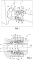
Figure 1 is a schematic perspective view of portions of a domestic appliance assembly having at least one gas pipe according to the present invention, with parts removed for clarity; -
Figure 2 is a sectionized side-view of details of the domestic appliance assembly ofFigure 1 , with parts removed for clarity; -
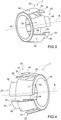
Figure 3 is a perspective view of a detail of the gas pipe ofFigures 1 and 2 , with parts removed for clarity; and -
Figure 4 is a perspective view of a variation of the detail ofFigure 3 , with parts removed for clarity. - With particular reference to
Figure 1 ,number 1 indicates as a whole a domestic appliance assembly comprising at least a domestic appliance 2 (only partially shown to the extend necessary for the comprehension of the present invention), such as a gas cooker or gas hob, and agas pipe 3 connectable to and/or connected to (seeFigure 2 )domestic appliance 2. - In particular,
gas pipe 3 is configured to supply and/or feed a gas todomestic appliance 2. Even more particular,gas pipe 3 is also connectable to a gas supply, such as e.g. a gas bottle or a gas supply circuit (of e.g. a housing location). - According to some non-limiting embodiments,
domestic appliance 2 is of the free-standing type or the built-in type. - With particular reference to
Figures 1 and 2 ,domestic appliance 2 comprises agas inlet duct 4, in particular extending along a longitudinal axis A, hosting and/or being configured to receive and/or to host at least a portion ofgas pipe 3 and configured to receive the gas fromgas pipe 3, in particular for further distribution of the gas withindomestic appliance 2. E.g.gas inlet duct 4 could be connected to further ducts configured to a feed the gas to a gas burning valve. - With particular reference to
Figures 1 to 3 ,gas pipe 3 comprises at least: - a
tube portion 5, in particular being of a metallic material, such as aluminium or copper and, having anend section 6 configured to be inserted intogas inlet duct 4, in particular for feeding the gas intodomestic appliance 2; and - a locking element 7 (externally) connected to end
section 6 and configured to lock and/or blockend section 6 withingas inlet duct 4. - In particular, locking
element 7 is configured to ensure that, onceend section 6 sits and/or is inserted withingas inlet duct 4, an undesired decoupling and/or disconnection ofgas pipe 3 fromdomestic appliance 2 is avoided. - In more detail,
end section 6 comprises and/or carries anoutlet 8 for allowing an outflow of the gas from tube portion 5 (and into gas inlet duct 4). - Preferentially,
end section 6 and/ortube portion 5 extends along a longitudinal axis B, in particular defining a central axis. In particular, axes A and B are parallel, even more particular coaxial, to one another withend section 6 sitting withingas inlet duct 4. - Even more particular, in use,
end portion 6 is inserted intogas inlet duct 4 by means of a movement ofend portion 6 into an insertion direction parallel to axis A. - Preferentially,
end section 6 and/ortube portion 5 has a cylindrical shape. - In particular,
end section 6 is designed to fit into at least a portion ofgas inlet duct 4. - According to some non-limiting embodiments,
domestic appliance 2 orgas pipe 3 comprises awasher 9 configured to interact withend section 6 andgas inlet duct 4. In particular,washer 9 guarantees that withend section 6 being placed withingas inlet duct 4, no fluidic connection betweenend section 6 and an outer environment can occur. - Preferentially,
washer 9 surrounds and sits on a part ofend section 6 and is placed within arespective seat 10 ofgas inlet duct 4. - Preferentially,
washer 9 is placed withingas inlet duct 4 prior to insertion ofend portion 6 intogas inlet duct 4. - Advantageously, locking
element 7 comprises one or more abutment surfaces 15 configured to abut against anengagement surface 16 or respective engagement surfaces ofgas inlet duct 4 for impeding a removal ofend section 6 from gas inlet duct after insertion ofend section 6 intogas inlet duct 4. In this manner, it is ensured that once tube portion 5 (and, accordingly gas pipe 3) is coupled todomestic appliance 2, any uncontrolled decoupling oftube portion 5 and/orgas pipe 3 is impeded. - In particular, abutment surfaces 15 are configured to abut against
engagement surface 16 at least during a movement ofend portion 6 into a removing direction opposed to the insertion direction. In such way, any possibility to further removeend portion 6 is blocked. Preferentially, lockingelement 7 is configured such to avoid any play ofend portion 6 once being inserted ingas inlet duct 4. - Preferentially, at least a
terminal portion 17 of lockingelement 7 is arranged withingas inlet duct 4 withend section 6 being inserted withingas inlet duct 4, so thatend section 6 andterminal portion 17 are locked withingas inlet duct 4. In particular,terminal portion 17 carries abutment surfaces 15. - According to some non-limiting embodiments, locking
element 7 is moveable and/or controllable between an active configuration at which abutment surfaces 15 are adapted to abut againstengagement surface 16 and an inactive configuration for allowing an introduction and/or removal of end section 6 (and terminal portion 17) intogas inlet duct 4. In particular, in use, lockingelement 7 is moved into the inactive configuration for allowing an introduction of end section 6 (and terminal portion 17) intogas inlet duct 4. Preferentially, in use, lockingelement 7 is also controlled into the inactive configuration for allowing a removal of end section 6 (and terminal portion 17) fromgas inlet duct 4. - In particular, after arrangement of
end section 6 withingas inlet duct 4, abutment surfaces 15 are detached fromengagement surface 16 when controlling and/or moving, in use, lockingelement 7 into the inactive configuration. - According to some non-limiting embodiments, locking
element 7 comprises a coupling portion, in particular an annular and/or ring-shapedcoupling portion 18, being connected to endsection 6, in particular by being in contact with anouter surface 19 ofend section 6. In particular,coupling portion 18 is connected to endsection 6 such that a sliding movement ofcoupling portion 18 into a direction parallel to axis B is disabled and/or impeded. - In particular,
coupling portion 18 is applied to endsection 6 by means of co-axial sliding. - Preferentially,
coupling portion 18 surroundsend section 6. - In particular,
coupling portion 18 is coaxially arranged onend section 6. In other words, a central axis ofcoupling portion 18 is coaxial with axis B. - Preferentially,
end section 6 comprises a first annular thickening 20 and a second annular thickening 21 being (axially) disposed from one another, and in particular defining a housing seat for couplingportion 18. In particular,coupling portion 18 is arranged betweenannular thickenings coupling portion 18 parallel to axis B (thereby, impeding also an axial movement of locking element 7). In particular,contact portion 18 contacts bothannular thickening 20 andannular thickening 21. - According to some non-limiting embodiments, locking
element 7 comprises one ormore fins 23, each one connected to and extending from couplingportion 18 and carrying onerespective abutment surface 15. - Preferentially,
fins 23 are equally spaced angularly around a central axis ofcoupling portion 18. - Preferentially, each
fin 23 comprises a first end being connected to couplingportion 18 and a second end opposed to the first end. - Preferably, a first (radial) distance between each first end and
outer surface 19 is smaller than a second (radial) distance between therespective abutment surface 15 andouter surface 19 and/or a third (radial) distance between the respective second end and outer surface 19 (the first, second and third (radial) distance being defined with respect to axis B and according to a respective reference axis perpendicular to axis B). - Preferentially, each
fin 23 extends from couplingportion 18 so that eachfin 23 and coupling portion define and/or describe a respective angle being larger than 0° and smaller than 90°. - In particular, each
fin 23 is connected to couplingportion 18 in a deformable and/or moveable manner, in particular so as to allow for moving therespective abutment surface 15 to or away from outer surface 19 (i.e. for modifying the second distance). - Preferentially, each
fin 23 comprises afirst plate portion 24 being connected to couplingportion 18 and carrying the respective first end and asecond plate portion 25 protruding fromfirst plate portion 24 in an inclined manner (and towards outer surface 19) and having therespective abutment surface 15. - Preferably, each
fin 23 also comprises athird plate portion 26 connected and protruding from the respective second plate portion 25 (and away from the respective first plate portion 24). In particular, eachthird plate portion 26 and the respectivesecond plate portion 25 are inclined with respect to one another. - Preferably,
terminal portion 17 comprisescoupling portion 18 and at least a respective section of eachfin 23. In particular,terminal portion 17 also comprisesfirst plate portions 24,second plate portions 25 and at least partiallythird plate portions 26. - In particular, with
end section 6 being arranged within gas inlet duct 4 a portion of eachthird plate portion 26 is accessible (e.g. to an operator) and/or is arranged outside ofgas inlet duct 4. - According to some preferred non-limiting embodiments, locking
element 7 is biased in the active configuration. - In particular, in use, locking
element 7 moves and/or is moveable from the active configuration to the inactive configuration during insertion ofend section 6 intogas inlet duct 4 and is based into the active configuration after insertion ofend section 6 withingas inlet duct 4 for lockingend section 6 withingas inlet duct 4. - According to some preferred non-limiting embodiments, each
abutment surface 15 and/or eachfin 23 is moveable into a respective direction D1 transversal to axis B or into a respective direction D2 opposed to direction D1 for moving and/or controllinglocking element 7 between the active configuration and the inactive configuration. - In particular, movement of each
abutment surface 15 into the respective direction D1 and into the respective direction D2 movesabutment surface 15 respectively towards and away fromouter surface 19. - Preferentially, each
abutment surface 15 is moveable into a first limit position and a second limit position, in particular at whichabutment surface 15 is respectively distal from and adjacent toouter surface 19. In particular, lockingelement 6 is controlled in the active configuration and the inactive configuration withabutment surfaces 15 being arranged at respectively the corresponding first limit position and the corresponding second limit position. - According to some preferred non-limiting embodiments,
gas pipe 3, inparticular locking element 7, comprises one or more interaction surfaces 30 configured to interact, during an insertion of end section 6 (and partially of locking element 7) intogas inlet duct 4, withgas inlet duct 4, in particular with anedge 31 ofgas inlet duct 4 delimiting anopening 32 ofgas inlet duct 4, so as to move lockingelement 7 from the active configuration to the inactive configuration. - In particular, each
fin 23, even more particular the respectivefirst plate portion 24, comprises onerespective interaction surface 30. Even more particular, in use, interaction surfaces 30 interact simultaneously withgas inlet duct 4, inparticular edge 31. - In particular, each
interaction surface 30 is configured such that the interaction ofinteraction surface 30 withgas inlet duct 4, in particular withedge 31, results in movement of therespective abutment surface 15 towards and/or to the second limit position. - Preferentially, each
interaction surface 30 is configured such that, in use, during insertion ofend section 6 intogas inlet duct 4, therespective abutment surface 15 is gradually moved from the respective first limit position to the respective second limit position. - In particular, each
third plate portion 26 is configured to allow for manually (e.g. by a user pressing on the respective third plate portion 26) move abutment surfaces 15 to the respective second limit position. This can be useful in the case one wants to removeend portion 6 out of gas inlet duct 4 (by movingend portion 6 into the removal direction). - With particular reference to
Figures 1 and 2 ,gas inlet duct 4 comprises an inner (annular)groove 33 being at least partially delimited byengagement surface 16 and by anauxiliary surface 34 ofgas inlet duct 4 facingengagement surface 16. In particular,groove 33 is interposed betweenopening 32 andseat 10. - In particular,
engagement surface 16 is closer to opening 32 thanauxiliary surface 34. In other words,engagement surface 16 is interposed betweenauxiliary surface 34 andopening 32. - According to some preferred non-limiting embodiments, a first radial extension (with respect to axis A) of
opening 32 is smaller than a second radial extension of groove 33 (with respect to axis A). - In particular, the first radial extension is such to allow for an introduction of
end portion 6 intogas inlet duct 4. Furthermore, the first radial extension is such that interaction surfaces 30 interact withedge 31. - In use,
gas pipe 3 is connected todomestic appliance 2 by placingend portion 6 withingas inlet duct 4, in particular by moving end portion 6 (and tube portion 5) into the insertion direction. - In particular, once
end section 6 is arranged withingas inlet duct 4, lockingelement 7 interacts withgas inlet duct 4 so as to avoid any (uncontrolled) removal ofend portion 6 out ofgas inlet duct 4. - Even more particular, locking
element 7 locks endportion 6 withingas inlet duct 4 byabutment surfaces 15 abutting againstengagement surface 16, thereby blocking movement ofend portion 6 out ofgas inlet duct 4. - During the insertion of
end portion 6 intogas inlet duct 4, lockingelement 7 is controlled from its active configuration to its inactive configuration. Once,end portion 6 is inserted withingas inlet duct 4, lockingelement 7 is biased into its active configuration so that abutment surfaces 15 abut againstengagement surface 16. - In particular, during the insertion of
end portion 6 intogas inlet duct 4, abutment surfaces 15 move, in particular by movement of therespective fins 23, into the respective direction D1. Even more particular, movement ofabutment surface 15 into the respective direction D1 is controlled by interaction of the respective interaction surfaces 30 withgas inlet duct 4, inparticular edge 31, and the continuous movement ofend portion 6 into gas inlet duct 4 (and along the insertion direction). Alternatively, a user can direct abutment surfaces 15 into the respective direction D1 by pressing the respectivethird plate portions 26. - Even more particular, during the insertion of
end portion 6 intogas inlet duct 4, abutment surfaces 15 move from the respective first limit position towards (and to) the respective second limit position. - Furthermore, after insertion of
end portion 6 intogas inlet duct 4, abutment surfaces 15, inparticular fins 23, move into the respective direction D2. In particular, abutment surfaces 15 move from the respective second limit position to the respective first limit position. - Once,
end portion 6 is inserted withingas inlet duct 4,end portion 6 seals in cooperation withwasher 9 any fluidic connection betweenoutlet 8 and the outer environment. - Preferentially, removal of
end portion 6 out ofgas inlet duct 4 allows disconnectinggas pipe 3 fromdomestic appliance 2. - In particular, removal of
end portion 6 out ofgas inlet duct 4, requires to control and/or move lockingelement 7 from the active configuration into the inactive configuration, followed by a movement ofend portion 6 into the removal direction and out ofgas inlet duct 4. - Even more particular, control of locking
element 7 into the inactive configuration is achieved by moving abutments surface 15 into the respective direction D1. E.g. this is achieved by pressing thethird plate portions 26. - With particular reference to
Figure 4 , numeral 7' indicates a variant of the locking element ofgas pipe 3. As locking element 7' is similar to lockingelement 7 the following description is limited to the differences between locking element 7' and lockingelement 7 using the same references for equivalent or similar parts. - In particular, locking element 7' differs from locking
element 7 in that therespective coupling portion 18 comprises a side cut 35. In particular, side cut 35 allows an alternative means of arranging locking element 7' onend portion 6. - As the operation of
gas pipe 3 having locking element 7' is similar to the operation ofgas pipe 3 havinglocking element 7, we refer to the above-provided description. - The advantages of
domestic appliance assembly 1 havinggas pipe 3 and/or ofgas pipe 3 according to the present invention will be clear from the foregoing description. - In particular, by relying on locking
element 7 or 7' it is possible to couplegas pipe 3, inparticular tube portion 5, todomestic appliance 2 by a simple axial movement ofend portion 6 intogas inlet duct 4. Abutment of abutment surfaces 15 onengagement surface 16 impedes removal ofend portion 6 fromgas inlet duct 4. - An additional advantage is seen in that
locking element 7 and 7' are biased in the active configuration. This guarantees thatend portion 6 is locked withingas inlet duct 4, once insertion has been terminated. - Another advantage can be seen in that
gas pipe 3 can be coupled to adomestic appliance 2 also by less trained personnel. - A further advantage resides in that the coupling of
gas pipe 3 todomestic appliance 2 can also be realized by means of a robot. - Clearly, changes may be made to
domestic appliance assembly 1 and/orgas pipe 3 without, however, departing from the scope of the present invention. -
- 1
- Domestic appliance assembly
- 2
- Domestic appliance
- 3
- Gas pipe
- 4
- Gas inlet duct
- 5
- Tube portion
- 6
- End section
- 7, 7'
- Locking element
- 8
- Outlet
- 9
- Washer
- 10
- Seat
- 15
- Abutment surface
- 16
- Engagement surface
- 17
- Terminal portion
- 18
- Coupling portion
- 19
- Outer surface
- 20
- First annular thickening
- 21
- Second annular thickening
- 23
- Fins
- 24
- First plate portion
- 25
- Second plate portion
- 26
- Third plate portion
- 30
- Interaction surfaces
- 31
- Edge
- 32
- Opening
- 33
- Inner groove
- 34
- Auxiliary surface
- 35
- Side-cut
- A
- Longitudinal axis
- B
- Longitudinal axis
Claims (15)
- Gas pipe (3) adapted to be coupled to a domestic appliance (2), the domestic appliance (2) comprising a gas inlet duct (4);
the gas pipe (3) comprises at least:- a tube portion (5) having an end section (6) configured to be inserted into the gas inlet duct (4); and- a locking element (7) connected to the end section (6) and configured to lock the end section (6) within the gas inlet duct (4);wherein the locking element (7) comprises at least one abutment surface (15) configured to abut against an engagement surface (16) of the gas inlet duct (4) for impeding a removal of the end section (6) from the gas inlet duct (4) after insertion of the end section (6) into the gas inlet duct (4). - Gas pipe according to claim 1, wherein at least a terminal portion (17) of the locking element (7) is arranged within the gas inlet duct (4) with the end section (6) being inserted within the gas inlet duct (4);
wherein the locking element (7) is configured to lock the end section (6) and the terminal portion (17) within the gas inlet duct (4). - Gas pipe according to claim 1 or 2, wherein the locking element (7) is moveable and/or controllable between an active configuration at which the abutment surface (15) is adapted to abut against the engagement surface (16) and an inactive configuration for allowing an introduction and/or removal of the end section (6) into the gas inlet duct (4).
- Gas pipe according to claim 3, wherein the locking element (7) comprises an interaction surface (30) configured to interact, during an insertion of the end section (6) into the gas inlet duct (4), with the gas inlet duct (4), in particular with an edge (31) of the gas inlet duct (4) so as to move the locking element (7) from the active configuration to the inactive configuration.
- Gas pipe according to claim 3 or 4, wherein the locking element (7) is biased into the active configuration;
wherein, in use, the locking element (7) moves and/or is moveable from the active configuration to the inactive configuration during insertion of the end section (6) into the gas inlet duct (4) and is biased into the active configuration after insertion of the end section (6) within the gas inlet duct (4). - Gas pipe according to any one of claims 3 to 5, wherein the end portion (6) extends along a longitudinal axis (B);
wherein the abutment surface (15) is moveable into a direction (D1; D2) transversal to the longitudinal axis (B) for moving the locking element (7) between the active configuration and the inactive configuration. - Gas pipe according to any one of the preceding claims, wherein the locking element (7) comprises a coupling portion (18), in particular an annular and/or ring-shaped coupling portion, being in contact with an outer surface (19) of the end portion (6).
- Gas pipe according to claim 7, wherein the end section (6) comprises a first annular thickening (20) and a second annular thickening (21) being disposed, in particular axially disposed, from one another;
wherein the coupling portion (18) is arranged between the first annular thickening (20) and the second annular thickening (21), in particular for impeding an axial movement of the locking element (7). - Gas pipe according to claim 7 or 8, wherein the locking element (7) comprises at least one fin (23) connected to and extending from the coupling portion (18) and carrying and/or having the abutment surface (15).
- Gas pipe according to claim 9, wherein the locking element (7) comprises a plurality of fins (23) each one connected to and extending from the coupling portion (18) and each one carrying one respective abutment surface (15) configured to abut against the engagement surface (16); in particular the fins (23) are equally spaced angularly around a central axis of the coupling portion (18).
- Gas pipe according to any one of claims 7 to 10, wherein the coupling portion (18) and the end section (6) are coaxial to one another.
- Gas pipe according to any one of claims 7 to 11, wherein the coupling portion (18) comprises a side cut (35) for allowing arrangement of the locking element (7) on the end portion (6).
- Domestic appliance assembly (1) comprising a domestic appliance (2) having a gas inlet duct (4) carrying and/or having an engagement surface (16) and a gas pipe (3) according to any one of the preceding claims.
- Domestic appliance assembly according to claim 13, wherein the gas inlet duct (4) comprises an inner groove (33) being at least partially delimited by the engagement surface (16).
- Domestic appliance assembly according to claim 14, wherein the gas inlet duct (4) comprises an opening (32) having a first radial extension and the inner groove (33) comprises a second radial extension being larger than the first radial extension.
Priority Applications (2)
| Application Number | Priority Date | Filing Date | Title |
|---|---|---|---|
| EP20197352.6A EP3971462B1 (en) | 2020-09-22 | 2020-09-22 | Domestic appliance having a gas pipe |
| BR102021018594-5A BR102021018594A2 (en) | 2020-09-22 | 2021-09-17 | Gas pipe and household appliance set incorporating a gas pipe |
Applications Claiming Priority (1)
| Application Number | Priority Date | Filing Date | Title |
|---|---|---|---|
| EP20197352.6A EP3971462B1 (en) | 2020-09-22 | 2020-09-22 | Domestic appliance having a gas pipe |
Publications (2)
| Publication Number | Publication Date |
|---|---|
| EP3971462A1 true EP3971462A1 (en) | 2022-03-23 |
| EP3971462B1 EP3971462B1 (en) | 2024-07-10 |
Family
ID=72613863
Family Applications (1)
| Application Number | Title | Priority Date | Filing Date |
|---|---|---|---|
| EP20197352.6A Active EP3971462B1 (en) | 2020-09-22 | 2020-09-22 | Domestic appliance having a gas pipe |
Country Status (2)
| Country | Link |
|---|---|
| EP (1) | EP3971462B1 (en) |
| BR (1) | BR102021018594A2 (en) |
Cited By (1)
| Publication number | Priority date | Publication date | Assignee | Title |
|---|---|---|---|---|
| EP4293267A1 (en) * | 2022-06-13 | 2023-12-20 | Witzenmann GmbH | Plug-in pipe connection |
Citations (4)
| Publication number | Priority date | Publication date | Assignee | Title |
|---|---|---|---|---|
| DE3940114A1 (en) * | 1989-12-05 | 1991-06-06 | Werner Lanz | Coupling with resilient ring for tube or cable - has matching conical surfaces amplifying grip and forcing spikes deeper into sheath around end of tube |
| DE4011756A1 (en) * | 1990-04-11 | 1991-10-17 | Knapp Mikrohydraulik Gmbh | Hydraulic coupling between two components |
| US5732984A (en) * | 1980-10-29 | 1998-03-31 | Proprietary Technology, Inc. | Manually releasable quick connector |
| DE19755826C1 (en) * | 1997-12-16 | 1999-05-20 | Raymond A & Cie | Releasable connector for pressure hoses |
-
2020
- 2020-09-22 EP EP20197352.6A patent/EP3971462B1/en active Active
-
2021
- 2021-09-17 BR BR102021018594-5A patent/BR102021018594A2/en unknown
Patent Citations (4)
| Publication number | Priority date | Publication date | Assignee | Title |
|---|---|---|---|---|
| US5732984A (en) * | 1980-10-29 | 1998-03-31 | Proprietary Technology, Inc. | Manually releasable quick connector |
| DE3940114A1 (en) * | 1989-12-05 | 1991-06-06 | Werner Lanz | Coupling with resilient ring for tube or cable - has matching conical surfaces amplifying grip and forcing spikes deeper into sheath around end of tube |
| DE4011756A1 (en) * | 1990-04-11 | 1991-10-17 | Knapp Mikrohydraulik Gmbh | Hydraulic coupling between two components |
| DE19755826C1 (en) * | 1997-12-16 | 1999-05-20 | Raymond A & Cie | Releasable connector for pressure hoses |
Cited By (1)
| Publication number | Priority date | Publication date | Assignee | Title |
|---|---|---|---|---|
| EP4293267A1 (en) * | 2022-06-13 | 2023-12-20 | Witzenmann GmbH | Plug-in pipe connection |
Also Published As
| Publication number | Publication date |
|---|---|
| EP3971462B1 (en) | 2024-07-10 |
| BR102021018594A2 (en) | 2022-06-07 |
Similar Documents
| Publication | Publication Date | Title |
|---|---|---|
| EP3971462B1 (en) | Domestic appliance having a gas pipe | |
| US11665792B2 (en) | Microwave oven with adapted LED light | |
| EP0014487B1 (en) | Cooking hob for built-in assembly | |
| US6453675B1 (en) | Combustor mounting for gas turbine engine | |
| US20110126816A1 (en) | Gas distribution unit for a cooking appliance | |
| US10634261B2 (en) | Attachment structure for actuator-specific solenoid valve and actuator-equipped valve | |
| EP3270063B1 (en) | Mounting arrangement for a user interface of a gas cooking appliance | |
| GB2367599A (en) | Water feed device for domestic appliance | |
| KR101730248B1 (en) | Gas burner | |
| EP2665969B1 (en) | Multi purpose gas burner | |
| EP3022488B1 (en) | Head assembly for a radiant burner | |
| US6213152B1 (en) | Safety gas valve arrangement for a cooking hob | |
| WO2018007156A2 (en) | A household appliance having an illuminated rotary control button | |
| AU2016214703A1 (en) | Fixation system for gas valves | |
| EP3933272B1 (en) | Gas stove | |
| CN213929538U (en) | Gas valve and gas stove | |
| EP4150257B1 (en) | Gas stove | |
| CN210857373U (en) | Bench type water tap mounting structure | |
| WO2018114168A1 (en) | Gas burner arrangement and hob comprising a gas burner arrangement | |
| CA2234338C (en) | Modular gas appliance system | |
| WO2019098953A2 (en) | Improvement in gas oven lighter and a terminal box placed on plug-in feeder cable | |
| US20210180794A1 (en) | Switch assembly | |
| WO2020135985A1 (en) | A cooking device comprising a safety member | |
| EP2933565B1 (en) | A cooking device having a gas distribution pipe whose mounting is facilitated | |
| US6273140B1 (en) | Cluster valve for semiconductor wafer processing systems |
Legal Events
| Date | Code | Title | Description |
|---|---|---|---|
| PUAI | Public reference made under article 153(3) epc to a published international application that has entered the european phase |
Free format text: ORIGINAL CODE: 0009012 |
|
| STAA | Information on the status of an ep patent application or granted ep patent |
Free format text: STATUS: THE APPLICATION HAS BEEN PUBLISHED |
|
| AK | Designated contracting states |
Kind code of ref document: A1 Designated state(s): AL AT BE BG CH CY CZ DE DK EE ES FI FR GB GR HR HU IE IS IT LI LT LU LV MC MK MT NL NO PL PT RO RS SE SI SK SM TR |
|
| STAA | Information on the status of an ep patent application or granted ep patent |
Free format text: STATUS: REQUEST FOR EXAMINATION WAS MADE |
|
| 17P | Request for examination filed |
Effective date: 20220923 |
|
| RBV | Designated contracting states (corrected) |
Designated state(s): AL AT BE BG CH CY CZ DE DK EE ES FI FR GB GR HR HU IE IS IT LI LT LU LV MC MK MT NL NO PL PT RO RS SE SI SK SM TR |
|
| STAA | Information on the status of an ep patent application or granted ep patent |
Free format text: STATUS: EXAMINATION IS IN PROGRESS |
|
| 17Q | First examination report despatched |
Effective date: 20230125 |
|
| GRAP | Despatch of communication of intention to grant a patent |
Free format text: ORIGINAL CODE: EPIDOSNIGR1 |
|
| STAA | Information on the status of an ep patent application or granted ep patent |
Free format text: STATUS: GRANT OF PATENT IS INTENDED |
|
| RIC1 | Information provided on ipc code assigned before grant |
Ipc: F23K 5/00 20060101ALI20240126BHEP Ipc: F24C 3/00 20060101ALI20240126BHEP Ipc: F16L 37/098 20060101AFI20240126BHEP |
|
| INTG | Intention to grant announced |
Effective date: 20240212 |
|
| P01 | Opt-out of the competence of the unified patent court (upc) registered |
Effective date: 20240306 |
|
| GRAS | Grant fee paid |
Free format text: ORIGINAL CODE: EPIDOSNIGR3 |
|
| GRAA | (expected) grant |
Free format text: ORIGINAL CODE: 0009210 |
|
| STAA | Information on the status of an ep patent application or granted ep patent |
Free format text: STATUS: THE PATENT HAS BEEN GRANTED |
|
| AK | Designated contracting states |
Kind code of ref document: B1 Designated state(s): AL AT BE BG CH CY CZ DE DK EE ES FI FR GB GR HR HU IE IS IT LI LT LU LV MC MK MT NL NO PL PT RO RS SE SI SK SM TR |
|
| REG | Reference to a national code |
Ref country code: CH Ref legal event code: EP |
|
| REG | Reference to a national code |
Ref country code: DE Ref legal event code: R096 Ref document number: 602020033652 Country of ref document: DE |
|
| REG | Reference to a national code |
Ref country code: LT Ref legal event code: MG9D |
|
| REG | Reference to a national code |
Ref country code: NL Ref legal event code: MP Effective date: 20240710 |
|
| PG25 | Lapsed in a contracting state [announced via postgrant information from national office to epo] |
Ref country code: PT Free format text: LAPSE BECAUSE OF FAILURE TO SUBMIT A TRANSLATION OF THE DESCRIPTION OR TO PAY THE FEE WITHIN THE PRESCRIBED TIME-LIMIT Effective date: 20241111 |
|
| REG | Reference to a national code |
Ref country code: AT Ref legal event code: MK05 Ref document number: 1702299 Country of ref document: AT Kind code of ref document: T Effective date: 20240710 |
|
| PG25 | Lapsed in a contracting state [announced via postgrant information from national office to epo] |
Ref country code: NL Free format text: LAPSE BECAUSE OF FAILURE TO SUBMIT A TRANSLATION OF THE DESCRIPTION OR TO PAY THE FEE WITHIN THE PRESCRIBED TIME-LIMIT Effective date: 20240710 |
|
| PG25 | Lapsed in a contracting state [announced via postgrant information from national office to epo] |
Ref country code: PT Free format text: LAPSE BECAUSE OF FAILURE TO SUBMIT A TRANSLATION OF THE DESCRIPTION OR TO PAY THE FEE WITHIN THE PRESCRIBED TIME-LIMIT Effective date: 20241111 Ref country code: NL Free format text: LAPSE BECAUSE OF FAILURE TO SUBMIT A TRANSLATION OF THE DESCRIPTION OR TO PAY THE FEE WITHIN THE PRESCRIBED TIME-LIMIT Effective date: 20240710 |
|
| PG25 | Lapsed in a contracting state [announced via postgrant information from national office to epo] |
Ref country code: NO Free format text: LAPSE BECAUSE OF FAILURE TO SUBMIT A TRANSLATION OF THE DESCRIPTION OR TO PAY THE FEE WITHIN THE PRESCRIBED TIME-LIMIT Effective date: 20241010 |
|
| PG25 | Lapsed in a contracting state [announced via postgrant information from national office to epo] |
Ref country code: GR Free format text: LAPSE BECAUSE OF FAILURE TO SUBMIT A TRANSLATION OF THE DESCRIPTION OR TO PAY THE FEE WITHIN THE PRESCRIBED TIME-LIMIT Effective date: 20241011 Ref country code: FI Free format text: LAPSE BECAUSE OF FAILURE TO SUBMIT A TRANSLATION OF THE DESCRIPTION OR TO PAY THE FEE WITHIN THE PRESCRIBED TIME-LIMIT Effective date: 20240710 Ref country code: PL Free format text: LAPSE BECAUSE OF FAILURE TO SUBMIT A TRANSLATION OF THE DESCRIPTION OR TO PAY THE FEE WITHIN THE PRESCRIBED TIME-LIMIT Effective date: 20240710 |
|
| PG25 | Lapsed in a contracting state [announced via postgrant information from national office to epo] |
Ref country code: BG Free format text: LAPSE BECAUSE OF FAILURE TO SUBMIT A TRANSLATION OF THE DESCRIPTION OR TO PAY THE FEE WITHIN THE PRESCRIBED TIME-LIMIT Effective date: 20240710 |
|
| PG25 | Lapsed in a contracting state [announced via postgrant information from national office to epo] |
Ref country code: LV Free format text: LAPSE BECAUSE OF FAILURE TO SUBMIT A TRANSLATION OF THE DESCRIPTION OR TO PAY THE FEE WITHIN THE PRESCRIBED TIME-LIMIT Effective date: 20240710 |
|
| PG25 | Lapsed in a contracting state [announced via postgrant information from national office to epo] |
Ref country code: IS Free format text: LAPSE BECAUSE OF FAILURE TO SUBMIT A TRANSLATION OF THE DESCRIPTION OR TO PAY THE FEE WITHIN THE PRESCRIBED TIME-LIMIT Effective date: 20241110 Ref country code: AT Free format text: LAPSE BECAUSE OF FAILURE TO SUBMIT A TRANSLATION OF THE DESCRIPTION OR TO PAY THE FEE WITHIN THE PRESCRIBED TIME-LIMIT Effective date: 20240710 |
|
| PG25 | Lapsed in a contracting state [announced via postgrant information from national office to epo] |
Ref country code: HR Free format text: LAPSE BECAUSE OF FAILURE TO SUBMIT A TRANSLATION OF THE DESCRIPTION OR TO PAY THE FEE WITHIN THE PRESCRIBED TIME-LIMIT Effective date: 20240710 |
|
| PG25 | Lapsed in a contracting state [announced via postgrant information from national office to epo] |
Ref country code: ES Free format text: LAPSE BECAUSE OF FAILURE TO SUBMIT A TRANSLATION OF THE DESCRIPTION OR TO PAY THE FEE WITHIN THE PRESCRIBED TIME-LIMIT Effective date: 20240710 Ref country code: RS Free format text: LAPSE BECAUSE OF FAILURE TO SUBMIT A TRANSLATION OF THE DESCRIPTION OR TO PAY THE FEE WITHIN THE PRESCRIBED TIME-LIMIT Effective date: 20241010 |
|
| PG25 | Lapsed in a contracting state [announced via postgrant information from national office to epo] |
Ref country code: RS Free format text: LAPSE BECAUSE OF FAILURE TO SUBMIT A TRANSLATION OF THE DESCRIPTION OR TO PAY THE FEE WITHIN THE PRESCRIBED TIME-LIMIT Effective date: 20241010 Ref country code: PL Free format text: LAPSE BECAUSE OF FAILURE TO SUBMIT A TRANSLATION OF THE DESCRIPTION OR TO PAY THE FEE WITHIN THE PRESCRIBED TIME-LIMIT Effective date: 20240710 Ref country code: NO Free format text: LAPSE BECAUSE OF FAILURE TO SUBMIT A TRANSLATION OF THE DESCRIPTION OR TO PAY THE FEE WITHIN THE PRESCRIBED TIME-LIMIT Effective date: 20241010 Ref country code: LV Free format text: LAPSE BECAUSE OF FAILURE TO SUBMIT A TRANSLATION OF THE DESCRIPTION OR TO PAY THE FEE WITHIN THE PRESCRIBED TIME-LIMIT Effective date: 20240710 Ref country code: IS Free format text: LAPSE BECAUSE OF FAILURE TO SUBMIT A TRANSLATION OF THE DESCRIPTION OR TO PAY THE FEE WITHIN THE PRESCRIBED TIME-LIMIT Effective date: 20241110 Ref country code: HR Free format text: LAPSE BECAUSE OF FAILURE TO SUBMIT A TRANSLATION OF THE DESCRIPTION OR TO PAY THE FEE WITHIN THE PRESCRIBED TIME-LIMIT Effective date: 20240710 Ref country code: GR Free format text: LAPSE BECAUSE OF FAILURE TO SUBMIT A TRANSLATION OF THE DESCRIPTION OR TO PAY THE FEE WITHIN THE PRESCRIBED TIME-LIMIT Effective date: 20241011 Ref country code: FI Free format text: LAPSE BECAUSE OF FAILURE TO SUBMIT A TRANSLATION OF THE DESCRIPTION OR TO PAY THE FEE WITHIN THE PRESCRIBED TIME-LIMIT Effective date: 20240710 Ref country code: ES Free format text: LAPSE BECAUSE OF FAILURE TO SUBMIT A TRANSLATION OF THE DESCRIPTION OR TO PAY THE FEE WITHIN THE PRESCRIBED TIME-LIMIT Effective date: 20240710 Ref country code: BG Free format text: LAPSE BECAUSE OF FAILURE TO SUBMIT A TRANSLATION OF THE DESCRIPTION OR TO PAY THE FEE WITHIN THE PRESCRIBED TIME-LIMIT Effective date: 20240710 Ref country code: AT Free format text: LAPSE BECAUSE OF FAILURE TO SUBMIT A TRANSLATION OF THE DESCRIPTION OR TO PAY THE FEE WITHIN THE PRESCRIBED TIME-LIMIT Effective date: 20240710 |
|
| REG | Reference to a national code |
Ref country code: DE Ref legal event code: R119 Ref document number: 602020033652 Country of ref document: DE |
|
| PG25 | Lapsed in a contracting state [announced via postgrant information from national office to epo] |
Ref country code: RO Free format text: LAPSE BECAUSE OF FAILURE TO SUBMIT A TRANSLATION OF THE DESCRIPTION OR TO PAY THE FEE WITHIN THE PRESCRIBED TIME-LIMIT Effective date: 20240710 Ref country code: SM Free format text: LAPSE BECAUSE OF FAILURE TO SUBMIT A TRANSLATION OF THE DESCRIPTION OR TO PAY THE FEE WITHIN THE PRESCRIBED TIME-LIMIT Effective date: 20240710 Ref country code: DK Free format text: LAPSE BECAUSE OF FAILURE TO SUBMIT A TRANSLATION OF THE DESCRIPTION OR TO PAY THE FEE WITHIN THE PRESCRIBED TIME-LIMIT Effective date: 20240710 |
|
| PG25 | Lapsed in a contracting state [announced via postgrant information from national office to epo] |
Ref country code: MC Free format text: LAPSE BECAUSE OF FAILURE TO SUBMIT A TRANSLATION OF THE DESCRIPTION OR TO PAY THE FEE WITHIN THE PRESCRIBED TIME-LIMIT Effective date: 20240710 Ref country code: EE Free format text: LAPSE BECAUSE OF FAILURE TO SUBMIT A TRANSLATION OF THE DESCRIPTION OR TO PAY THE FEE WITHIN THE PRESCRIBED TIME-LIMIT Effective date: 20240710 |
|
| PG25 | Lapsed in a contracting state [announced via postgrant information from national office to epo] |
Ref country code: CZ Free format text: LAPSE BECAUSE OF FAILURE TO SUBMIT A TRANSLATION OF THE DESCRIPTION OR TO PAY THE FEE WITHIN THE PRESCRIBED TIME-LIMIT Effective date: 20240710 |
|
| PG25 | Lapsed in a contracting state [announced via postgrant information from national office to epo] |
Ref country code: SK Free format text: LAPSE BECAUSE OF FAILURE TO SUBMIT A TRANSLATION OF THE DESCRIPTION OR TO PAY THE FEE WITHIN THE PRESCRIBED TIME-LIMIT Effective date: 20240710 |
|
| REG | Reference to a national code |
Ref country code: CH Ref legal event code: PL |
|
| PLBE | No opposition filed within time limit |
Free format text: ORIGINAL CODE: 0009261 |
|
| STAA | Information on the status of an ep patent application or granted ep patent |
Free format text: STATUS: NO OPPOSITION FILED WITHIN TIME LIMIT |
|
| PG25 | Lapsed in a contracting state [announced via postgrant information from national office to epo] |
Ref country code: LU Free format text: LAPSE BECAUSE OF NON-PAYMENT OF DUE FEES Effective date: 20240922 |
|
| 26N | No opposition filed |
Effective date: 20250411 |
|
| PG25 | Lapsed in a contracting state [announced via postgrant information from national office to epo] |
Ref country code: DE Free format text: LAPSE BECAUSE OF NON-PAYMENT OF DUE FEES Effective date: 20250401 |
|
| REG | Reference to a national code |
Ref country code: BE Ref legal event code: MM Effective date: 20240930 |
|
| PG25 | Lapsed in a contracting state [announced via postgrant information from national office to epo] |
Ref country code: BE Free format text: LAPSE BECAUSE OF NON-PAYMENT OF DUE FEES Effective date: 20240930 |
|
| PG25 | Lapsed in a contracting state [announced via postgrant information from national office to epo] |
Ref country code: FR Free format text: LAPSE BECAUSE OF NON-PAYMENT OF DUE FEES Effective date: 20240930 |
|
| PG25 | Lapsed in a contracting state [announced via postgrant information from national office to epo] |
Ref country code: CH Free format text: LAPSE BECAUSE OF NON-PAYMENT OF DUE FEES Effective date: 20240930 |
|
| PG25 | Lapsed in a contracting state [announced via postgrant information from national office to epo] |
Ref country code: IE Free format text: LAPSE BECAUSE OF NON-PAYMENT OF DUE FEES Effective date: 20240922 |
|
| PG25 | Lapsed in a contracting state [announced via postgrant information from national office to epo] |
Ref country code: SE Free format text: LAPSE BECAUSE OF FAILURE TO SUBMIT A TRANSLATION OF THE DESCRIPTION OR TO PAY THE FEE WITHIN THE PRESCRIBED TIME-LIMIT Effective date: 20240710 |
|
| PGFP | Annual fee paid to national office [announced via postgrant information from national office to epo] |
Ref country code: IT Payment date: 20250922 Year of fee payment: 6 |
|
| PGFP | Annual fee paid to national office [announced via postgrant information from national office to epo] |
Ref country code: GB Payment date: 20250923 Year of fee payment: 6 |
|
| PG25 | Lapsed in a contracting state [announced via postgrant information from national office to epo] |
Ref country code: CY Free format text: LAPSE BECAUSE OF FAILURE TO SUBMIT A TRANSLATION OF THE DESCRIPTION OR TO PAY THE FEE WITHIN THE PRESCRIBED TIME-LIMIT; INVALID AB INITIO Effective date: 20200922 |
|
| PG25 | Lapsed in a contracting state [announced via postgrant information from national office to epo] |
Ref country code: HU Free format text: LAPSE BECAUSE OF FAILURE TO SUBMIT A TRANSLATION OF THE DESCRIPTION OR TO PAY THE FEE WITHIN THE PRESCRIBED TIME-LIMIT; INVALID AB INITIO Effective date: 20200922 |