EP3971442B1 - Hollow spring and manufacturing method therefor - Google Patents
Hollow spring and manufacturing method therefor Download PDFInfo
- Publication number
- EP3971442B1 EP3971442B1 EP20935059.4A EP20935059A EP3971442B1 EP 3971442 B1 EP3971442 B1 EP 3971442B1 EP 20935059 A EP20935059 A EP 20935059A EP 3971442 B1 EP3971442 B1 EP 3971442B1
- Authority
- EP
- European Patent Office
- Prior art keywords
- steel tube
- tubular member
- stress
- die
- hollow spring
- Prior art date
- Legal status (The legal status is an assumption and is not a legal conclusion. Google has not performed a legal analysis and makes no representation as to the accuracy of the status listed.)
- Active
Links
Images


Classifications
-
- F—MECHANICAL ENGINEERING; LIGHTING; HEATING; WEAPONS; BLASTING
- F16—ENGINEERING ELEMENTS AND UNITS; GENERAL MEASURES FOR PRODUCING AND MAINTAINING EFFECTIVE FUNCTIONING OF MACHINES OR INSTALLATIONS; THERMAL INSULATION IN GENERAL
- F16F—SPRINGS; SHOCK-ABSORBERS; MEANS FOR DAMPING VIBRATION
- F16F1/00—Springs
- F16F1/02—Springs made of steel or other material having low internal friction; Wound, torsion, leaf, cup, ring or the like springs, the material of the spring not being relevant
-
- B—PERFORMING OPERATIONS; TRANSPORTING
- B21—MECHANICAL METAL-WORKING WITHOUT ESSENTIALLY REMOVING MATERIAL; PUNCHING METAL
- B21F—WORKING OR PROCESSING OF METAL WIRE
- B21F1/00—Bending wire other than coiling; Straightening wire
- B21F1/02—Straightening
- B21F1/026—Straightening and cutting
-
- B—PERFORMING OPERATIONS; TRANSPORTING
- B21—MECHANICAL METAL-WORKING WITHOUT ESSENTIALLY REMOVING MATERIAL; PUNCHING METAL
- B21F—WORKING OR PROCESSING OF METAL WIRE
- B21F23/00—Feeding wire in wire-working machines or apparatus
-
- B—PERFORMING OPERATIONS; TRANSPORTING
- B21—MECHANICAL METAL-WORKING WITHOUT ESSENTIALLY REMOVING MATERIAL; PUNCHING METAL
- B21F—WORKING OR PROCESSING OF METAL WIRE
- B21F3/00—Coiling wire into particular forms
- B21F3/02—Coiling wire into particular forms helically
-
- B—PERFORMING OPERATIONS; TRANSPORTING
- B60—VEHICLES IN GENERAL
- B60G—VEHICLE SUSPENSION ARRANGEMENTS
- B60G21/00—Interconnection systems for two or more resiliently-suspended wheels, e.g. for stabilising a vehicle body with respect to acceleration, deceleration or centrifugal forces
- B60G21/02—Interconnection systems for two or more resiliently-suspended wheels, e.g. for stabilising a vehicle body with respect to acceleration, deceleration or centrifugal forces permanently interconnected
- B60G21/04—Interconnection systems for two or more resiliently-suspended wheels, e.g. for stabilising a vehicle body with respect to acceleration, deceleration or centrifugal forces permanently interconnected mechanically
- B60G21/05—Interconnection systems for two or more resiliently-suspended wheels, e.g. for stabilising a vehicle body with respect to acceleration, deceleration or centrifugal forces permanently interconnected mechanically between wheels on the same axle but on different sides of the vehicle, i.e. the left and right wheel suspensions being interconnected
- B60G21/055—Stabiliser bars
-
- C—CHEMISTRY; METALLURGY
- C21—METALLURGY OF IRON
- C21D—MODIFYING THE PHYSICAL STRUCTURE OF FERROUS METALS; GENERAL DEVICES FOR HEAT TREATMENT OF FERROUS OR NON-FERROUS METALS OR ALLOYS; MAKING METAL MALLEABLE, e.g. BY DECARBURISATION OR TEMPERING
- C21D7/00—Modifying the physical properties of iron or steel by deformation
- C21D7/02—Modifying the physical properties of iron or steel by deformation by cold working
- C21D7/04—Modifying the physical properties of iron or steel by deformation by cold working of the surface
- C21D7/06—Modifying the physical properties of iron or steel by deformation by cold working of the surface by shot-peening or the like
-
- C—CHEMISTRY; METALLURGY
- C21—METALLURGY OF IRON
- C21D—MODIFYING THE PHYSICAL STRUCTURE OF FERROUS METALS; GENERAL DEVICES FOR HEAT TREATMENT OF FERROUS OR NON-FERROUS METALS OR ALLOYS; MAKING METAL MALLEABLE, e.g. BY DECARBURISATION OR TEMPERING
- C21D9/00—Heat treatment, e.g. annealing, hardening, quenching or tempering, adapted for particular articles; Furnaces therefor
- C21D9/02—Heat treatment, e.g. annealing, hardening, quenching or tempering, adapted for particular articles; Furnaces therefor for springs
-
- F—MECHANICAL ENGINEERING; LIGHTING; HEATING; WEAPONS; BLASTING
- F16—ENGINEERING ELEMENTS AND UNITS; GENERAL MEASURES FOR PRODUCING AND MAINTAINING EFFECTIVE FUNCTIONING OF MACHINES OR INSTALLATIONS; THERMAL INSULATION IN GENERAL
- F16F—SPRINGS; SHOCK-ABSORBERS; MEANS FOR DAMPING VIBRATION
- F16F1/00—Springs
- F16F1/02—Springs made of steel or other material having low internal friction; Wound, torsion, leaf, cup, ring or the like springs, the material of the spring not being relevant
- F16F1/025—Springs made of steel or other material having low internal friction; Wound, torsion, leaf, cup, ring or the like springs, the material of the spring not being relevant characterised by having a particular shape
-
- F—MECHANICAL ENGINEERING; LIGHTING; HEATING; WEAPONS; BLASTING
- F16—ENGINEERING ELEMENTS AND UNITS; GENERAL MEASURES FOR PRODUCING AND MAINTAINING EFFECTIVE FUNCTIONING OF MACHINES OR INSTALLATIONS; THERMAL INSULATION IN GENERAL
- F16F—SPRINGS; SHOCK-ABSORBERS; MEANS FOR DAMPING VIBRATION
- F16F1/00—Springs
- F16F1/02—Springs made of steel or other material having low internal friction; Wound, torsion, leaf, cup, ring or the like springs, the material of the spring not being relevant
- F16F1/14—Torsion springs consisting of bars or tubes
- F16F1/145—Torsion springs consisting of bars or tubes with means for modifying the spring characteristics
-
- B—PERFORMING OPERATIONS; TRANSPORTING
- B60—VEHICLES IN GENERAL
- B60G—VEHICLE SUSPENSION ARRANGEMENTS
- B60G2202/00—Indexing codes relating to the type of spring, damper or actuator
- B60G2202/10—Type of spring
- B60G2202/13—Torsion spring
- B60G2202/135—Stabiliser bar and/or tube
-
- B—PERFORMING OPERATIONS; TRANSPORTING
- B60—VEHICLES IN GENERAL
- B60G—VEHICLE SUSPENSION ARRANGEMENTS
- B60G2206/00—Indexing codes related to the manufacturing of suspensions: constructional features, the materials used, procedures or tools
- B60G2206/01—Constructional features of suspension elements, e.g. arms, dampers, springs
- B60G2206/012—Hollow or tubular elements
-
- B—PERFORMING OPERATIONS; TRANSPORTING
- B60—VEHICLES IN GENERAL
- B60G—VEHICLE SUSPENSION ARRANGEMENTS
- B60G2206/00—Indexing codes related to the manufacturing of suspensions: constructional features, the materials used, procedures or tools
- B60G2206/01—Constructional features of suspension elements, e.g. arms, dampers, springs
- B60G2206/40—Constructional features of dampers and/or springs
- B60G2206/42—Springs
- B60G2206/427—Stabiliser bars or tubes
-
- B—PERFORMING OPERATIONS; TRANSPORTING
- B60—VEHICLES IN GENERAL
- B60G—VEHICLE SUSPENSION ARRANGEMENTS
- B60G2206/00—Indexing codes related to the manufacturing of suspensions: constructional features, the materials used, procedures or tools
- B60G2206/01—Constructional features of suspension elements, e.g. arms, dampers, springs
- B60G2206/70—Materials used in suspensions
- B60G2206/72—Steel
- B60G2206/724—Wires, bars or the like
-
- B—PERFORMING OPERATIONS; TRANSPORTING
- B60—VEHICLES IN GENERAL
- B60G—VEHICLE SUSPENSION ARRANGEMENTS
- B60G2206/00—Indexing codes related to the manufacturing of suspensions: constructional features, the materials used, procedures or tools
- B60G2206/01—Constructional features of suspension elements, e.g. arms, dampers, springs
- B60G2206/80—Manufacturing procedures
- B60G2206/81—Shaping
-
- C—CHEMISTRY; METALLURGY
- C21—METALLURGY OF IRON
- C21D—MODIFYING THE PHYSICAL STRUCTURE OF FERROUS METALS; GENERAL DEVICES FOR HEAT TREATMENT OF FERROUS OR NON-FERROUS METALS OR ALLOYS; MAKING METAL MALLEABLE, e.g. BY DECARBURISATION OR TEMPERING
- C21D9/00—Heat treatment, e.g. annealing, hardening, quenching or tempering, adapted for particular articles; Furnaces therefor
- C21D9/08—Heat treatment, e.g. annealing, hardening, quenching or tempering, adapted for particular articles; Furnaces therefor for tubular bodies or pipes
-
- F—MECHANICAL ENGINEERING; LIGHTING; HEATING; WEAPONS; BLASTING
- F16—ENGINEERING ELEMENTS AND UNITS; GENERAL MEASURES FOR PRODUCING AND MAINTAINING EFFECTIVE FUNCTIONING OF MACHINES OR INSTALLATIONS; THERMAL INSULATION IN GENERAL
- F16F—SPRINGS; SHOCK-ABSORBERS; MEANS FOR DAMPING VIBRATION
- F16F2224/00—Materials; Material properties
- F16F2224/02—Materials; Material properties solids
- F16F2224/0208—Alloys
-
- F—MECHANICAL ENGINEERING; LIGHTING; HEATING; WEAPONS; BLASTING
- F16—ENGINEERING ELEMENTS AND UNITS; GENERAL MEASURES FOR PRODUCING AND MAINTAINING EFFECTIVE FUNCTIONING OF MACHINES OR INSTALLATIONS; THERMAL INSULATION IN GENERAL
- F16F—SPRINGS; SHOCK-ABSORBERS; MEANS FOR DAMPING VIBRATION
- F16F2226/00—Manufacturing; Treatments
- F16F2226/04—Assembly or fixing methods; methods to form or fashion parts
-
- F—MECHANICAL ENGINEERING; LIGHTING; HEATING; WEAPONS; BLASTING
- F16—ENGINEERING ELEMENTS AND UNITS; GENERAL MEASURES FOR PRODUCING AND MAINTAINING EFFECTIVE FUNCTIONING OF MACHINES OR INSTALLATIONS; THERMAL INSULATION IN GENERAL
- F16F—SPRINGS; SHOCK-ABSORBERS; MEANS FOR DAMPING VIBRATION
- F16F2228/00—Functional characteristics, e.g. variability, frequency-dependence
- F16F2228/08—Functional characteristics, e.g. variability, frequency-dependence pre-stressed
-
- F—MECHANICAL ENGINEERING; LIGHTING; HEATING; WEAPONS; BLASTING
- F16—ENGINEERING ELEMENTS AND UNITS; GENERAL MEASURES FOR PRODUCING AND MAINTAINING EFFECTIVE FUNCTIONING OF MACHINES OR INSTALLATIONS; THERMAL INSULATION IN GENERAL
- F16F—SPRINGS; SHOCK-ABSORBERS; MEANS FOR DAMPING VIBRATION
- F16F2238/00—Type of springs or dampers
- F16F2238/02—Springs
- F16F2238/024—Springs torsional
-
- Y—GENERAL TAGGING OF NEW TECHNOLOGICAL DEVELOPMENTS; GENERAL TAGGING OF CROSS-SECTIONAL TECHNOLOGIES SPANNING OVER SEVERAL SECTIONS OF THE IPC; TECHNICAL SUBJECTS COVERED BY FORMER USPC CROSS-REFERENCE ART COLLECTIONS [XRACs] AND DIGESTS
- Y02—TECHNOLOGIES OR APPLICATIONS FOR MITIGATION OR ADAPTATION AGAINST CLIMATE CHANGE
- Y02P—CLIMATE CHANGE MITIGATION TECHNOLOGIES IN THE PRODUCTION OR PROCESSING OF GOODS
- Y02P10/00—Technologies related to metal processing
- Y02P10/20—Recycling
Definitions
- the present invention relates to a method of manufacturing a hollow spring having a prolonged fatigue life.
- a hollow spring to a vehicle such as an automobile has been considered to meet the demand for the reduction in the weight of the vehicle.
- a hollow stabilizer that is formed by performing the bending processing to a steel tube or the like so that the steel tube has a predetermined shape.
- the demand for the weight reduction of the vehicle has tended to further increase, and the demand for stabilizers from a solid stabilizer to the hollow stabilizer has still further increased (refer to Patent Document 1).
- the stress on an inner surface of a tube is lower than that on an outer surface of the tube, but if the shot peening is applied to the outer surface to impart the compressive residual stress to the outer surface, the stress on the outer surface is relieved and the stress difference between the outer and the inner surfaces is reduced. If the thickness of the hollow spring is reduced in order to reduce the weight of the hollow spring, this tendency becomes more remarkable, and the breakage starting from the inner surface may occur.
- Patent Document 2 discloses a technique in which a reflection member is arranged to a hole of a pipe, the projected shot is reflected by a reflection unit, and the shot peening is applied to an inner surface to impart the compressive residual stress to the inner surface.
- Patent Document 3 discloses a technique in which a reflection member of the shot is supported relative to an inner surface of a hole of a pipe by a guide member and is moved along the hole of the pipe by a wire. Attention is also drawn to the disclosures of WO2018/152226A1 and JPS56-134022A .
- FIG. 12 is a top view showing the distribution of the magnitude of the maximum principal stress generated when the load is applied to the tubular member 10.
- the maximum principal stress in this case corresponds to the tensile stress which is a positive value.
- FIG. 12 shows that as a color of an area is dark, the maximum principal stress is larger, and thus, in a black area, the maximum principal stress is the largest, and alternatively, in a white area, the maximum principal stress is the smallest. From FIG. 12 , it can be observed that the maximum principal stress is the largest at a first bending portion 13 in the vicinity of the first end 11.
- the compressive residual stress can be applied to the inner surface of a specific portion such as the bending portion at which the tensile stress concentrates and becomes the high stress when a load is applied to a hollow stabilizer. This enables the reduction in the tensile stress at the high stress portion by the compressive residual stress to prolong the fatigue life. Further, the compressive residual stress can be imparted to the bending portion of the tubular member 10 such that the direction of the minimum principal stress corresponding to the compressive residual stress matches the direction of the maximum principal stress corresponding to the tensile stress.
Landscapes
- Engineering & Computer Science (AREA)
- Mechanical Engineering (AREA)
- General Engineering & Computer Science (AREA)
- Chemical & Material Sciences (AREA)
- Crystallography & Structural Chemistry (AREA)
- Materials Engineering (AREA)
- Metallurgy (AREA)
- Organic Chemistry (AREA)
- Thermal Sciences (AREA)
- Physics & Mathematics (AREA)
- Springs (AREA)
- Vehicle Body Suspensions (AREA)
- Heat Treatment Of Articles (AREA)
Description
- The present invention relates to a method of manufacturing a hollow spring having a prolonged fatigue life.
- The use of a hollow spring to a vehicle such as an automobile has been considered to meet the demand for the reduction in the weight of the vehicle. In order to reduce a roll of a vehicle body caused at the time of cornering, as a kind of the hollow spring, provided, for example, is a hollow stabilizer that is formed by performing the bending processing to a steel tube or the like so that the steel tube has a predetermined shape. In recent years, from the viewpoint of saving resources and energy, the demand for the weight reduction of the vehicle has tended to further increase, and the demand for stabilizers from a solid stabilizer to the hollow stabilizer has still further increased (refer to Patent Document 1).
- In the hollow spring, normally, the stress on an inner surface of a tube is lower than that on an outer surface of the tube, but if the shot peening is applied to the outer surface to impart the compressive residual stress to the outer surface, the stress on the outer surface is relieved and the stress difference between the outer and the inner surfaces is reduced. If the thickness of the hollow spring is reduced in order to reduce the weight of the hollow spring, this tendency becomes more remarkable, and the breakage starting from the inner surface may occur.
- Generally, the fatigue breaking occurs from a surface, and thus, by applying the compressive residual stress on an inner surface of the hollow spring, the stress on the inner surface can be relieved, and accordingly, a fatigue life of the hollow spring can be prolonged. For example, Patent Document 2 discloses a technique in which a reflection member is arranged to a hole of a pipe, the projected shot is reflected by a reflection unit, and the shot peening is applied to an inner surface to impart the compressive residual stress to the inner surface. Patent Document 3 discloses a technique in which a reflection member of the shot is supported relative to an inner surface of a hole of a pipe by a guide member and is moved along the hole of the pipe by a wire. Attention is also drawn to the disclosures of
WO2018/152226A1 andJPS56-134022A -
- Patent Document 1:
JP H07-89325 A - Patent Document 2
JP 2009-107031 A - Patent Document 3
JP 2009-125827 A - However, the techniques disclosed in Patent Literatures 2 and 3 require certain components in equipment such as a dust collector for collecting the reflection member disposed to the hole of the pipe, the guide member, the wire, and the shot. Further, there has been a concern that an inner surface of a bending portion of a pipe may be scratched because, at the bending portion, when the reflection member is moved by the wire, the guide member slides along the inner surface. Still further, sometimes, the techniques have been not able to cope with a pipe with a more complicated shape or a smaller diameter because the reflection member or the like is arranged to the hole of the pipe and is moved.
- A present embodiment is proposed in view of the above described circumstances, and an object of the present invention to provide a method of manufacturing a hollow spring with a prolonged fatigue life by applying the compressive residual stress to an inner surface thereof.
- A method of manufacturing a hollow spring according to the present application is provided as claimed in
claim 1. - The pressing surface may reach a half of a circumference in the circumferential direction of the steel tube. The steel tube pressed with the die may be supported by a flat surface.
- The steel tube may be subjected to the bending processing to have a predetermined shape. The steel tube may be subjected to a heat treatment.
- According to the present invention, a fatigue life of a hollow spring can be prolonged by applying the compressive residual stress to an inner surface of a steel tube.
-
-
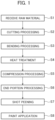
FIG. 1 is a flowchart illustrating a series of processes of manufacturing a hollow spring. -
FIG. 2 is a three-view drawing showing a tubular member. -
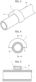
FIG. 3 is a perspective view showing a method of manufacturing a hollow spring applied to a straight portion of a tubular member. -
FIG. 4 is a side view showing a method of manufacturing a hollow spring applied to a straight portion of a tubular member. -
FIG. 5 is a cross sectional view showing a method of manufacturing a hollow spring applied to a straight portion of a tubular member. -
FIG. 6 is a perspective view showing the distribution of the minimum principal stress on an inner surface of a straight portion of a tubular member subjected to the compression processing. -
FIG. 7 is a graph showing results obtained by performing a fatigue test. -
FIG. 8 is a perspective view showing a method of manufacturing a hollow spring applied to a bending portion of a tubular member. -
FIG. 9 is a top view illustrating a method of manufacturing a hollow spring applied to a bending portion of a tubular member. -
FIG. 10 is a cross sectional view showing a method of manufacturing a hollow spring applied to a bending portion of a tubular member. -
FIG. 11 is a perspective view showing the distribution of the minimum principal stress on an inner surface of a bending portion of a tubular member subjected to the compression processing. -
FIG. 12 is a top view showing the distribution of the magnitude of the maximum principal stress generated when a load is applied to a tubular member. -
FIG. 13 is a partially enlarged perspective view showing the distribution of the magnitude of the maximum principal stress at a bending portion of the tubular member ofFIG. 12 . -
FIG. 14 is a perspective view showing the distribution of the maximum principal stress on an inner surface of the bending portion ofFIG. 13 . - Hereinafter, an embodiment of a hollow spring and a method of manufacturing the hollow spring will be described in detail with reference to the drawings. The hollow spring of the present embodiment is composed of a steel tube, and the fatigue strength of the hollow spring is enhanced by applying compressive force to an outer surface of the steel tube from a circumferential direction to impart compressive residual stress to an inner surface of the steel tube.
- In the present embodiment, descriptions will be given by assuming that a hollow stabilizer is the hollow spring. The hollow spring of the present embodiment corresponds to a main body of the hollow stabilizer obtained by excluding portions for connecting with other members formed at end portions from the entire hollow stabilizer. The hollow spring of the present embodiment is not limited to the hollow stabilizer, and can be applied to other types of hollow springs such as, for example, hollow coil springs for automobile suspensions.
- As shown in the flowchart of
FIG. 1 , the hollow stabilizer is manufactured through a series of processes of receiving (step S1) and cutting (step S2) the steel tube of a raw material, and of applying, to the steel tube of the raw material, bending processing (step S3), a heat treatment (step S4), compression processing (step S5), end portion processing (step S6), shot peening (step S7), and painting (step S8). - The method of manufacturing the hollow spring of the present embodiment corresponds to the process of the compression processing of step S5. In the method of manufacturing the hollow spring of the present embodiment, the steel tube subjected to the processes of the reception (step S1), cutting (step S2), the bending processing (step S3), and the heat treatment (step S4) is provided, and the compression processing is applied to the steel tube (step S5). The compression processing (step S5) may be performed after the process of the end portion processing (step S6) instead of being performed immediately after the process of the heat treatment (step S4).
- Although an order will be different from the order shown in
FIG. 1 , in the manufacturing process of the hollow stabilizer, the end portion processing (step S6) may be performed before the heat treatment (step S4). Even in the above case, the compression processing (step S5) is performed following the heat treatment (step S4). - In the following description, a steel tube which is subjected to the processes of steps S1 to S4 of
FIG. 1 and thereafter is applied with the method of manufacturing the hollow spring of the present embodiment corresponding to the process of step S5 is referred to as a tubular member for convenience. -
FIG. 2 is a three-view drawing showing thetubular member 10.FIG. 2(a) is a top view,FIG. 2(b) is a front view, andFIG. 2(c) is a side view. Thetubular member 10 is formed to have substantially a shape of C that is inverted to face leftward by performing the bending processing, and has afirst bending portion 13 in the vicinity of afirst end 11 and asecond bending portion 14 in the vicinity of asecond end 12, and further includes a straight portion in addition to thefirst bending portion 13 and thesecond bending portion 14. - As the method of manufacturing the hollow spring of the present embodiment, a method of performing the compression processing to the
tubular member 10 by pressing a die will be described. In the present embodiment, descriptions will be given for each of the straight portion and the bending portion of thetubular member 10 separately. - First, a case not according to the invention, will be described in which the present embodiment is applied to the straight portion of the
tubular member 10.FIGS. 3 to 5 are diagrams showing the method of manufacturing the hollow spring of the present embodiment applied to the straight portion of thetubular member 10.FIG. 3 is a perspective view,FIG. 4 is a side view, andFIG. 5 is a cross sectional view taken along a cross section V-V ofFIG. 4 . - The straight portion of the
tubular member 10 is supported by a flat top surface of a table that extends substantially horizontally (not shown). At a predetermined position of thetubular member 10 in an axial direction, thedie 1 is arranged so as to cover a predetermined width in the axial direction of an upper half portion of thetubular member 10. - The
die 1 has apressing surface 1a shaped such that the compressive force can be applied to at least a part of the outer surface of thetubular member 10 from the circumferential direction. More specifically, thepressing surface 1a extends in the circumferential direction along the outer surface of thetubular member 10 and reaches a half of a circumference in the circumferential direction so as to cover the upper half portion of thetubular member 10. Further, thedie 1 has apressing surface 1a with a round shape which faces and comes into contact with the outer surface of thetubular member 10 in the axial direction. Thedie 1 may be made of tool steel. - Pressing such the
die 1 causes the compressive force to be applied to thetubular member 10 from the circumferential direction so that the compression processing is performed on thetubular member 10. As shown inFIG. 5 , thepressing surface 1a with the round shape of thedie 1 contacts with a predetermined range of the outer surface of thetubular member 10 in a cross section extending in a radial direction of thetubular member 10. The range of the outer surface of thetubular member 10 contacting thepressing surface 1a extends to the upper half portion of thetubular member 10 in the circumferential direction, and an entire range in which thepressing surface 1a contacts the outer surface of thetubular member 10 forms an upper semicircle extending along the outer surface of thetubular member 10 in a plane orthogonal to an axis of thetubular member 10. - If the
die 1 is pressed in such the state, the compressive force is applied to thetubular member 10 from the circumferential direction, and the deformation in the axial direction of thetubular member 10 is caused in the vicinity of an range of the inner surface of thetubular member 10 corresponding to the range where thepressing surface 1a of thedie 1 contacts the outer surface, but the displacement is constrained by surrounding materials. Therefore, when the pressing load of thedie 1 is removed, the compressive residual stress is applied to the inner surface of thetubular member 10 in the axial direction. -
FIG. 6 is a perspective view showing the distribution of the minimum principal stress on the inner surface of the straight portion of thetubular member 10 applied with the compression processing. The distribution of the minimum principal stress is calculated based on a finite element method. The minimum principal stress in this case corresponds to the compressive stress which is a negative value. It was confirmed that the minimum principal stress was remained after the removal of the pressing load of thedie 1, and thus, it became clear that the compressive residual stress was applied to the inner surface. As can be seem from arrows inFIG. 6 , it can be observed that the minimum principal stress generally points in the axial direction of thetubular member 10. - Effects on the straight portion of the
tubular member 10 by performing the compression processing was confirmed by performing experiments. A steel tube subjected to the heat treatment was used as a target object of the compression processing. The steel tube had an outer diameter of 28.6 mm, the thickness of 4 mm, and the length of 300 mm. In the experiment, a strain gauge was attached to the inner surface of the steel tube, and the residual stress was calculated from the strain detected on the inner surface of the steel tube before and after performing the compression processing. - Table 1 shows experimental results of the relationship among the load applied to the
die 1, the strain and the residual stress. In Table 1, values in a column "during compression" are values obtained by applying the load to the press, and alternatively, values in a column "time of release" are values obtained by removing the load from the press.TABLE 1 APPLIED LOAD (N) STRAIN (µε) STRESS (MPa) DURING COMPRESSION TIME OF RELEASE DURING COMPRESSION TIME OF RELEASE 101640 -925 -32 -190.55 -6.592 127050 -1367 -257 -281.6 -52.942 152460 -2314 -1222 -476.68 -251.73 177870 -3261 -2187 -671.77 -450.52 203280 -4208 -3152 -866.85 -649.31 - As shown in Table 1, the stress of the inner surface of the steel tube took negative values in a column of "Time of release" at which the load was removed from the press and it was observed that the compressive residual stress was imparted on the inner surface of the steel tube by performing the compression processing. Further, it was observed that, as the applied load increases, the stress of the negative value of the inner surface of the steel tube at the time of release further decreases, and as the compressive force applied during the compression processing increases, the compressive residual stress further increases.
- Furthermore, the effect of the compressive residual stress applied to the straight portion of the
tubular member 10 was confirmed by performing a 4-point bending fatigue test. As a target object for performing the fatigue test, used is the steel tube which was used as the target object in the experiment of the compression processing, and is subjected to the compression processing by using the press of 152460 N among the loads shown in Table 1 under the same condition as in the experiment of the compression processing. - Table 2 shows the results obtained by performing the fatigue test for each of two target objects that are one target object subjected to the compression processing and the other target object not subjected to the compression processing.
Fig. 7 shows the results obtained by performing the fatigue test shown in Table 2 in a graph, and the graph has a horizontal axis representing the number of endurance and a vertical axis representing the applied stress. InFIG. 7 , data point A represents the steel tube not subjected to the compression processing, and alternatively, data point B represents the steel tube subjected to the compression processing.TABLE 2 APPLIED STRESS (MPa) NUMBER OF ENDURANCE COMPRESSION PROCESSING NOT PERFORMED 720 551000 684 848000 COMPRESSION PROCESSING PERFORMED 792 126000 756 616000 - The graph in
Fig. 7 shows, in a range in the vicinity of the number of endurance where the fatigue test was performed, two data points A representing the steel tube not subjected to the compression processing and alternatively two data points B representing the steel tube subjected to the compression processing, and each of the two data points A and the data points B are connected each other and extended to form a linear relationship between the number of endurance and the applied stress of the graph. With reference to the above, in both cases of the steel tube subjected to the compression processing and the steel tube not subjected to the compression processing, it was observed that, as the applied pressure increases, the number of endurance decreased more. On the other hand, it was observed that the number of endurance corresponding to the same applied stress was significantly increased in the case of the steel tube subjected to the compression processing than in the case of the steel tube not subjected to the compression processing. This clarified that the fatigue life of the tubular member is prolonged by applying the compression processing to the tubular member to impart the compressive residual stress to the inner surface. - Next, a case according to the invention, will be described in which the present embodiment is applied to the bending portions of the
tubular member 10.FIGS. 8 to 10 are diagrams showing the method of manufacturing the hollow spring of the present embodiment applied to the bending portions of thetubular member 10.FIG. 8 is a perspective view,FIG. 9 is a top view, andFIG. 10 is a cross sectional view taken along a cross section X-X ofFIG. 9 . - The bending portion of the
tubular member 10 is supported by a flat top surface of a table extending substantially horizontally (not shown). At a predetermined position of thetubular member 10 in the axial direction, adie 1 is arranged so as to cover a predetermined range of the upper half portion of thetubular member 10 in the axial direction. Thedie 1 applied to the bending portion of thetubular member 10 may have a shape different from that of thedie 1 applied to the straight portion of thetubular member 10 described above, but in order to clarify the correspondence relationship between them, descriptions are given by denoting them with a common reference numeral. - The
die 1 has thepressing surface 1a shaped such that the compressive force can be applied to at least a part of the outer surface of thetubular member 10 from the circumferential direction. More specifically, thepressing surface 1a extends in the circumferential direction along the outer surface of thetubular member 10 and reaches a half of a circumference in the circumferential direction so as to cover the upper half portion of thetubular member 10. Further, thedie 1 has thepressing surface 1a of a round shape which faces and contacts the outer surface of thetubular member 10 in the axial direction of thetubular member 10. Thepressing surface 1a of thedie 1 may be formed of tool steel. - Pressing such the
die 1 causes the compressive force to be applied to thetubular member 10 from the circumferential direction so that the compression processing is performed to thetubular member 10. In the case of the bending portion of thetubular member 10 also, similarly to the case of the straight portion shown inFIG. 5 , thepressing surface 1a with the round shape of thedie 1 contacts a predetermined range of the outer surface of thetubular member 10 in a cross section extending in a radial direction of thetubular member 10. As shown inFIG. 10 , the range of the outer surface of thetubular member 10 contacting thepressing surface 1a extends to the upper half portion of thetubular member 10 in the circumferential direction, and an entire range in which thepressing surface 1a contacts the outer surface of thetubular member 10 forms an upper semicircle extending along the outer surface of thetubular member 10 in a plane orthogonal to an axis of thetubular member 10. - If the
die 1 is pressed in such the state, the compressive force is applied to thetubular member 10 from the circumferential direction, and the deformation in the axial direction of thetubular member 10 is caused in the vicinity of an range of the inner surface of thetubular member 10 corresponding to the range where thepressing surface 1a of thedie 1 contacts the outer surface, but the displacement is constrained by surrounding materials. Therefore, when the pressing load of thedie 1 is removed, compressive residual stress is imparted to the inner surface of thetubular member 10 in the axial direction. -
FIG. 11 is a perspective view showing the distribution of the minimum principal stress on the inner surface of the bending portion of thetubular member 10 subjected to the compression processing. The distribution of the minimum principal stress is calculated based on a finite element method. The minimum principal stress in this case corresponds to the compressive stress which is a negative value. It was confirmed that the minimum principal stress was remained after the removal of the pressing load of thedie 1, and thus, it became clear that the compressive residual stress was imparted to the inner surface. As can be seen from arrows inFIG. 11 , it can be observed that the minimum principal stress generally point in the axial direction of thetubular member 10. -
FIG. 12 is a top view showing the distribution of the magnitude of the maximum principal stress generated when the load is applied to thetubular member 10. InFIG. 12 , the distribution of the magnitude of the maximum principal stress generated when the load is applied between thefirst end 11 and thesecond end 12 of thetubular member 10 is obtained based on the finite element method. The maximum principal stress in this case corresponds to the tensile stress which is a positive value.FIG. 12 shows that as a color of an area is dark, the maximum principal stress is larger, and thus, in a black area, the maximum principal stress is the largest, and alternatively, in a white area, the maximum principal stress is the smallest. FromFIG. 12 , it can be observed that the maximum principal stress is the largest at afirst bending portion 13 in the vicinity of thefirst end 11. -
FIG. 13 is a partially enlarged perspective view showing the distribution of the magnitude of the maximum principal stress at thefirst bending portion 13 of thetubular member 10 ofFIG. 12 . FromFIG. 13 , it can be observed that an area of thefirst bending portion 13, in which the maximum principal stress is large, generally extends along the axial direction of thetubular member 10. -
FIG. 14 is a diagram showing the distribution of the maximum principal stress at thefirst bending portion 13 ofFIG. 13 . The distribution of the maximum principal stress is calculated based on the finite element method. The maximum principal stress in this case also corresponds to the tensile stress which is a positive value. As shown by arrows inFIG. 14 , it is observed that a direction of the maximum principal stress generally points in the axial direction oftubular member 10. - With reference to the distribution of the minimum principal stress on the inner surface of the bending portion of the
tubular member 10 subjected to the compression processing shown inFIG. 11 , the minimum principal stress at the bending portion corresponding to the compressive residual stress imparted by performing the compression processing is approximately directed in the axial direction of thetubular member 10. The maximum principal stress corresponding to the tensile stress of thetubular member 10 generated when the load is applied to the tubular member as shown inFIGS. 13 and14 is approximately directed in the same axial direction as the direction of the minimum principal stress. Accordingly, the compressive residual stress of the negative value corresponding to the minimum principal stress can reduce the tensile stress which is the positive value corresponding to the maximum principal stress. - Therefore, by performing the compression processing and imparting the compressive residual stress, to a portion of the
tubular member 10 at which the large tensile stress is caused when being applied with a load, such as thefirst bending portion 13, the caused tensile stress is reduced, and accordingly the tensile stress can be relieved. This reduces the load imposed on the inner surface of thetubular member 10 due to the tensile stress, and accordingly, the fatigue life of thetubular member 10 can be prolonged. - As described above, according to the present embodiment, the compressive residual stress is applied to the inner surface of the
tubular member 10 configuring the hollow spring, and accordingly, the fatigue life of thetubular member 10 can be prolonged. Specifically, pressing thedie 1 enables the compressive residual stress to be imparted to the inner surface of a desired portion regardless of whether the portion is the straight portion or the bending portion of thetubular member 10. The compressive residual stress can be sufficiently imparted by pressing thedie 1, and thus, a complicated equipment configuration or the like is not required. - Further, the compressive residual stress can be applied to the inner surface of a specific portion such as the bending portion at which the tensile stress concentrates and becomes the high stress when a load is applied to a hollow stabilizer. This enables the reduction in the tensile stress at the high stress portion by the compressive residual stress to prolong the fatigue life. Further, the compressive residual stress can be imparted to the bending portion of the
tubular member 10 such that the direction of the minimum principal stress corresponding to the compressive residual stress matches the direction of the maximum principal stress corresponding to the tensile stress. - The present invention can be applied to a method of manufacturing a hollow spring used for a vehicle such as an automobile.
-
- 1
- die
- 1a
- Pressing surface
- 10
- Tubular member
- 11
- First end
- 12
- Second end
- 13
- First bending portion
- 14
- Second bending portion
Claims (5)
- A method of manufacturing a hollow spring, comprising:providing a steel tube (10) used for the hollow spring; andapplying compressive force to at least a portion of an outer surface of the steel tube (10) from a circumferential direction to apply compressive residual stress to at least a portion of an inner surface of the steel tube (10); whereina fatigue life of the steel tube (10) is prolonged by applying the compressive residual stress to the inner surface of the steel tube (10),applying the compressive force to the outer surface of the steel tube (10) comprises pressing the steel tube (10) with a die (1),the die (1) comprises a pressing surface (1a) shaped such that the compressive force can be applied to the at least the portion of the outer surface of the steel tube (10) from the circumferential direction,characterised in that:the at least a portion of the outer surface of the steel tube (10) includes the outer surface of a bending portion (13, 14) of the steel tube (10), andthe pressing surface (1a) includes a round shape that extends along the outer surface of the steel tube (10) in a circumferential direction and faces the outer surface of the steel tube (10) in an axial direction of the steel tube (10).
- The method according to claim 1, wherein
the pressing surface (1a) extends in the circumferential direction of the steel tube (10) over a half of a circumference. - The method according to any one of claims 1 or 2, wherein
the steel tube (10) pressed with the die (1) is supported by a flat surface. - The method according to any one of claims 1 to 3, wherein
the steel tube (10) is subjected to bending processing to have a predetermined shape. - The method according to any one of claims 1 to 4, wherein
the steel tube (10) is subjected to a heat treatment.
Applications Claiming Priority (1)
| Application Number | Priority Date | Filing Date | Title |
|---|---|---|---|
| PCT/JP2020/019498 WO2021229808A1 (en) | 2020-05-15 | 2020-05-15 | Hollow spring and manufacturing method therefor |
Publications (3)
| Publication Number | Publication Date |
|---|---|
| EP3971442A1 EP3971442A1 (en) | 2022-03-23 |
| EP3971442A4 EP3971442A4 (en) | 2022-08-03 |
| EP3971442B1 true EP3971442B1 (en) | 2025-07-09 |
Family
ID=78525619
Family Applications (1)
| Application Number | Title | Priority Date | Filing Date |
|---|---|---|---|
| EP20935059.4A Active EP3971442B1 (en) | 2020-05-15 | 2020-05-15 | Hollow spring and manufacturing method therefor |
Country Status (11)
| Country | Link |
|---|---|
| US (1) | US12135068B2 (en) |
| EP (1) | EP3971442B1 (en) |
| JP (1) | JP7266716B2 (en) |
| KR (1) | KR102698601B1 (en) |
| CN (1) | CN114025896B (en) |
| CA (1) | CA3144946C (en) |
| ES (1) | ES3035664T3 (en) |
| MX (1) | MX2021014424A (en) |
| PH (1) | PH12021553138A1 (en) |
| TW (1) | TWI801851B (en) |
| WO (1) | WO2021229808A1 (en) |
Families Citing this family (1)
| Publication number | Priority date | Publication date | Assignee | Title |
|---|---|---|---|---|
| EP3971442B1 (en) * | 2020-05-15 | 2025-07-09 | Mitsubishi Steel Mfg. Co., Ltd. | Hollow spring and manufacturing method therefor |
Citations (1)
| Publication number | Priority date | Publication date | Assignee | Title |
|---|---|---|---|---|
| JPS56134022A (en) * | 1980-03-24 | 1981-10-20 | Hitachi Ltd | Pipe bending method |
Family Cites Families (21)
| Publication number | Priority date | Publication date | Assignee | Title |
|---|---|---|---|---|
| JPS5978720A (en) | 1982-10-29 | 1984-05-07 | Toshio Yoshida | Production of corrosion resistant metallic pipe |
| JPH0789325A (en) | 1993-09-21 | 1995-04-04 | Mitsubishi Steel Mfg Co Ltd | Hollow stabilizer |
| JP4331300B2 (en) * | 1999-02-15 | 2009-09-16 | 日本発條株式会社 | Method for manufacturing hollow stabilizer |
| JP2000234688A (en) * | 1999-02-17 | 2000-08-29 | Usui Internatl Ind Co Ltd | Manufacture of common rail |
| US6418770B1 (en) * | 2000-12-08 | 2002-07-16 | Meritor Suspension Systems Company | Method for improving the fatigue life of a tubular stabilizer bar |
| JP4612527B2 (en) | 2005-11-04 | 2011-01-12 | 日本発條株式会社 | Hollow spring |
| JP5144209B2 (en) | 2007-10-26 | 2013-02-13 | 日本発條株式会社 | Reflective member for shot peening and shot peening method using the same |
| JP5066430B2 (en) | 2007-11-20 | 2012-11-07 | 日本発條株式会社 | Reflective member for shot peening and shot peening method using the same |
| JP2009274077A (en) * | 2008-05-12 | 2009-11-26 | Nippon Steel Corp | Method of press-forming tubular member having special-shaped cross section and tubular member having special-shaped cross section formed by the same method |
| JP5372548B2 (en) * | 2009-02-18 | 2013-12-18 | トピー工業株式会社 | Fastening structure for vehicle wheel |
| JP5511451B2 (en) * | 2010-03-16 | 2014-06-04 | 中央発條株式会社 | Manufacturing method of automotive stabilizer |
| JP5551024B2 (en) * | 2010-08-31 | 2014-07-16 | 三菱製鋼株式会社 | Slide device for electronic equipment |
| JP5923322B2 (en) * | 2012-01-31 | 2016-05-24 | 三菱製鋼株式会社 | Spring unit and slide mechanism |
| JP5361098B1 (en) * | 2012-09-14 | 2013-12-04 | 日本発條株式会社 | Compression coil spring and method of manufacturing the same |
| US8978432B2 (en) * | 2013-02-12 | 2015-03-17 | Caterpillar Inc. | Multi-stage tube hydroforming process |
| JP6262166B2 (en) * | 2014-03-31 | 2018-01-17 | Jfeスチール株式会社 | Bending press mold |
| CN106573285B (en) * | 2014-08-28 | 2019-08-13 | 日本制铁株式会社 | Manufacturing method of bent part and hot bending processing device of steel |
| CN109070175B (en) * | 2016-03-10 | 2021-02-05 | 日本制铁株式会社 | Manufacturing method of automobile parts and automobile parts |
| EP3583234A1 (en) | 2017-02-14 | 2019-12-25 | United States Steel Corporation | Compressive forming processes for enhancing collapse resistance in metallic tubular products |
| WO2019003397A1 (en) | 2017-06-28 | 2019-01-03 | 三菱製鋼株式会社 | METHOD FOR MANUFACTURING HOLLOW STABILIZER |
| EP3971442B1 (en) * | 2020-05-15 | 2025-07-09 | Mitsubishi Steel Mfg. Co., Ltd. | Hollow spring and manufacturing method therefor |
-
2020
- 2020-05-15 EP EP20935059.4A patent/EP3971442B1/en active Active
- 2020-05-15 JP JP2021570417A patent/JP7266716B2/en active Active
- 2020-05-15 ES ES20935059T patent/ES3035664T3/en active Active
- 2020-05-15 CA CA3144946A patent/CA3144946C/en active Active
- 2020-05-15 US US17/618,160 patent/US12135068B2/en active Active
- 2020-05-15 KR KR1020217039265A patent/KR102698601B1/en active Active
- 2020-05-15 PH PH1/2021/553138A patent/PH12021553138A1/en unknown
- 2020-05-15 CN CN202080046670.0A patent/CN114025896B/en active Active
- 2020-05-15 MX MX2021014424A patent/MX2021014424A/en unknown
- 2020-05-15 WO PCT/JP2020/019498 patent/WO2021229808A1/en not_active Ceased
-
2021
- 2021-04-26 TW TW110114926A patent/TWI801851B/en active
Patent Citations (1)
| Publication number | Priority date | Publication date | Assignee | Title |
|---|---|---|---|---|
| JPS56134022A (en) * | 1980-03-24 | 1981-10-20 | Hitachi Ltd | Pipe bending method |
Also Published As
| Publication number | Publication date |
|---|---|
| MX2021014424A (en) | 2022-01-06 |
| ES3035664T3 (en) | 2025-09-08 |
| JP7266716B2 (en) | 2023-04-28 |
| US12135068B2 (en) | 2024-11-05 |
| EP3971442A1 (en) | 2022-03-23 |
| TWI801851B (en) | 2023-05-11 |
| CN114025896B (en) | 2023-08-08 |
| CA3144946A1 (en) | 2021-11-18 |
| US20220170524A1 (en) | 2022-06-02 |
| KR102698601B1 (en) | 2024-08-23 |
| CN114025896A (en) | 2022-02-08 |
| JPWO2021229808A1 (en) | 2021-11-18 |
| BR112021026280A2 (en) | 2022-03-03 |
| WO2021229808A1 (en) | 2021-11-18 |
| TW202144687A (en) | 2021-12-01 |
| PH12021553138A1 (en) | 2022-07-25 |
| KR20220004161A (en) | 2022-01-11 |
| EP3971442A4 (en) | 2022-08-03 |
| CA3144946C (en) | 2023-10-24 |
Similar Documents
| Publication | Publication Date | Title |
|---|---|---|
| EP2298465B1 (en) | Press-forming method of tubular part having cross-section of irregular shape | |
| US7610938B2 (en) | Cylindrical rod and method for manufacturing the same | |
| EP1238750B1 (en) | Method of manufacturing hollow stabilizers | |
| EP3842164B1 (en) | Press forming method | |
| EP3971442B1 (en) | Hollow spring and manufacturing method therefor | |
| JP7318602B2 (en) | METHOD FOR MANUFACTURE OF TEST SPECIMEN AND METHOD FOR EVALUATION OF DELAYED FRACTURE CHARACTERISTICS OF HIGH-STRENGTH STEEL STEEL | |
| US20210316589A1 (en) | Hollow stabilizer, stabilizer manufacturing device, and method for manufacturing hollow stabilizer | |
| EP2344409B1 (en) | Load support for a jack, having bended parts. | |
| JPH08238526A (en) | Manufacturing method of small diameter ERW steel pipe with excellent fatigue property in bending part | |
| KR20190009249A (en) | method of manufacturing electrode assembly and device of pressing electrode assembly | |
| JP2750662B2 (en) | Upsetting method of metal material | |
| CN101175583A (en) | Cylindrical shaft and method for manufacturing same | |
| EP3805612B1 (en) | Pulley structure | |
| EP4417445B1 (en) | Hollow Stabilizer | |
| JP6331948B2 (en) | Torsion beam manufacturing method and torsion beam | |
| JP2006312980A (en) | Manufacturing method of connecting rod | |
| JP2009248187A (en) | Steel pipe for secondarily working into deformed cross section | |
| BR112021026280B1 (en) | METHOD OF MANUFACTURING A HOLLOW SPRING | |
| JP2002316215A (en) | Method of manufacturing bent article with excellent fatigue property, and bent article | |
| JPS6297740A (en) | Manufacture of axle made of electric resistance welded steel pipe |
Legal Events
| Date | Code | Title | Description |
|---|---|---|---|
| STAA | Information on the status of an ep patent application or granted ep patent |
Free format text: STATUS: THE INTERNATIONAL PUBLICATION HAS BEEN MADE |
|
| PUAI | Public reference made under article 153(3) epc to a published international application that has entered the european phase |
Free format text: ORIGINAL CODE: 0009012 |
|
| STAA | Information on the status of an ep patent application or granted ep patent |
Free format text: STATUS: REQUEST FOR EXAMINATION WAS MADE |
|
| 17P | Request for examination filed |
Effective date: 20211213 |
|
| AK | Designated contracting states |
Kind code of ref document: A1 Designated state(s): AL AT BE BG CH CY CZ DE DK EE ES FI FR GB GR HR HU IE IS IT LI LT LU LV MC MK MT NL NO PL PT RO RS SE SI SK SM TR |
|
| A4 | Supplementary search report drawn up and despatched |
Effective date: 20220704 |
|
| RIC1 | Information provided on ipc code assigned before grant |
Ipc: F16F 1/14 20060101ALI20220628BHEP Ipc: C21D 7/00 20060101ALI20220628BHEP Ipc: F16F 1/02 20060101AFI20220628BHEP |
|
| DAV | Request for validation of the european patent (deleted) | ||
| DAX | Request for extension of the european patent (deleted) | ||
| STAA | Information on the status of an ep patent application or granted ep patent |
Free format text: STATUS: EXAMINATION IS IN PROGRESS |
|
| 17Q | First examination report despatched |
Effective date: 20250114 |
|
| GRAP | Despatch of communication of intention to grant a patent |
Free format text: ORIGINAL CODE: EPIDOSNIGR1 |
|
| STAA | Information on the status of an ep patent application or granted ep patent |
Free format text: STATUS: GRANT OF PATENT IS INTENDED |
|
| INTG | Intention to grant announced |
Effective date: 20250324 |
|
| GRAS | Grant fee paid |
Free format text: ORIGINAL CODE: EPIDOSNIGR3 |
|
| GRAA | (expected) grant |
Free format text: ORIGINAL CODE: 0009210 |
|
| STAA | Information on the status of an ep patent application or granted ep patent |
Free format text: STATUS: THE PATENT HAS BEEN GRANTED |
|
| P01 | Opt-out of the competence of the unified patent court (upc) registered |
Free format text: CASE NUMBER: APP_20821/2025 Effective date: 20250501 |
|
| AK | Designated contracting states |
Kind code of ref document: B1 Designated state(s): AL AT BE BG CH CY CZ DE DK EE ES FI FR GB GR HR HU IE IS IT LI LT LU LV MC MK MT NL NO PL PT RO RS SE SI SK SM TR |
|
| REG | Reference to a national code |
Ref country code: GB Ref legal event code: FG4D |
|
| REG | Reference to a national code |
Ref country code: CH Ref legal event code: EP |
|
| REG | Reference to a national code |
Ref country code: IE Ref legal event code: FG4D |
|
| REG | Reference to a national code |
Ref country code: DE Ref legal event code: R096 Ref document number: 602020054414 Country of ref document: DE |
|
| REG | Reference to a national code |
Ref country code: ES Ref legal event code: FG2A Ref document number: 3035664 Country of ref document: ES Kind code of ref document: T3 Effective date: 20250908 |
|
| REG | Reference to a national code |
Ref country code: NL Ref legal event code: MP Effective date: 20250709 |
|
| PG25 | Lapsed in a contracting state [announced via postgrant information from national office to epo] |
Ref country code: PT Free format text: LAPSE BECAUSE OF FAILURE TO SUBMIT A TRANSLATION OF THE DESCRIPTION OR TO PAY THE FEE WITHIN THE PRESCRIBED TIME-LIMIT Effective date: 20251110 |
|
| PG25 | Lapsed in a contracting state [announced via postgrant information from national office to epo] |
Ref country code: NL Free format text: LAPSE BECAUSE OF FAILURE TO SUBMIT A TRANSLATION OF THE DESCRIPTION OR TO PAY THE FEE WITHIN THE PRESCRIBED TIME-LIMIT Effective date: 20250709 |
|
| REG | Reference to a national code |
Ref country code: AT Ref legal event code: MK05 Ref document number: 1812058 Country of ref document: AT Kind code of ref document: T Effective date: 20250709 |
|
| PG25 | Lapsed in a contracting state [announced via postgrant information from national office to epo] |
Ref country code: IS Free format text: LAPSE BECAUSE OF FAILURE TO SUBMIT A TRANSLATION OF THE DESCRIPTION OR TO PAY THE FEE WITHIN THE PRESCRIBED TIME-LIMIT Effective date: 20251109 |
|
| PG25 | Lapsed in a contracting state [announced via postgrant information from national office to epo] |
Ref country code: NO Free format text: LAPSE BECAUSE OF FAILURE TO SUBMIT A TRANSLATION OF THE DESCRIPTION OR TO PAY THE FEE WITHIN THE PRESCRIBED TIME-LIMIT Effective date: 20251009 |
|
| REG | Reference to a national code |
Ref country code: LT Ref legal event code: MG9D |
|
| PG25 | Lapsed in a contracting state [announced via postgrant information from national office to epo] |
Ref country code: AT Free format text: LAPSE BECAUSE OF FAILURE TO SUBMIT A TRANSLATION OF THE DESCRIPTION OR TO PAY THE FEE WITHIN THE PRESCRIBED TIME-LIMIT Effective date: 20250709 |
|
| PG25 | Lapsed in a contracting state [announced via postgrant information from national office to epo] |
Ref country code: FI Free format text: LAPSE BECAUSE OF FAILURE TO SUBMIT A TRANSLATION OF THE DESCRIPTION OR TO PAY THE FEE WITHIN THE PRESCRIBED TIME-LIMIT Effective date: 20250709 |
|
| PG25 | Lapsed in a contracting state [announced via postgrant information from national office to epo] |
Ref country code: HR Free format text: LAPSE BECAUSE OF FAILURE TO SUBMIT A TRANSLATION OF THE DESCRIPTION OR TO PAY THE FEE WITHIN THE PRESCRIBED TIME-LIMIT Effective date: 20250709 |
|
| PG25 | Lapsed in a contracting state [announced via postgrant information from national office to epo] |
Ref country code: GR Free format text: LAPSE BECAUSE OF FAILURE TO SUBMIT A TRANSLATION OF THE DESCRIPTION OR TO PAY THE FEE WITHIN THE PRESCRIBED TIME-LIMIT Effective date: 20251010 |
|
| PG25 | Lapsed in a contracting state [announced via postgrant information from national office to epo] |
Ref country code: SE Free format text: LAPSE BECAUSE OF FAILURE TO SUBMIT A TRANSLATION OF THE DESCRIPTION OR TO PAY THE FEE WITHIN THE PRESCRIBED TIME-LIMIT Effective date: 20250709 |
|
| PG25 | Lapsed in a contracting state [announced via postgrant information from national office to epo] |
Ref country code: LV Free format text: LAPSE BECAUSE OF FAILURE TO SUBMIT A TRANSLATION OF THE DESCRIPTION OR TO PAY THE FEE WITHIN THE PRESCRIBED TIME-LIMIT Effective date: 20250709 |
|
| PG25 | Lapsed in a contracting state [announced via postgrant information from national office to epo] |
Ref country code: PL Free format text: LAPSE BECAUSE OF FAILURE TO SUBMIT A TRANSLATION OF THE DESCRIPTION OR TO PAY THE FEE WITHIN THE PRESCRIBED TIME-LIMIT Effective date: 20250709 Ref country code: BG Free format text: LAPSE BECAUSE OF FAILURE TO SUBMIT A TRANSLATION OF THE DESCRIPTION OR TO PAY THE FEE WITHIN THE PRESCRIBED TIME-LIMIT Effective date: 20250709 |
|
| PG25 | Lapsed in a contracting state [announced via postgrant information from national office to epo] |
Ref country code: RS Free format text: LAPSE BECAUSE OF FAILURE TO SUBMIT A TRANSLATION OF THE DESCRIPTION OR TO PAY THE FEE WITHIN THE PRESCRIBED TIME-LIMIT Effective date: 20251009 |
|
| PG25 | Lapsed in a contracting state [announced via postgrant information from national office to epo] |
Ref country code: SM Free format text: LAPSE BECAUSE OF FAILURE TO SUBMIT A TRANSLATION OF THE DESCRIPTION OR TO PAY THE FEE WITHIN THE PRESCRIBED TIME-LIMIT Effective date: 20250709 |
|
| PG25 | Lapsed in a contracting state [announced via postgrant information from national office to epo] |
Ref country code: DK Free format text: LAPSE BECAUSE OF FAILURE TO SUBMIT A TRANSLATION OF THE DESCRIPTION OR TO PAY THE FEE WITHIN THE PRESCRIBED TIME-LIMIT Effective date: 20250709 |
|
| PG25 | Lapsed in a contracting state [announced via postgrant information from national office to epo] |
Ref country code: CZ Free format text: LAPSE BECAUSE OF FAILURE TO SUBMIT A TRANSLATION OF THE DESCRIPTION OR TO PAY THE FEE WITHIN THE PRESCRIBED TIME-LIMIT Effective date: 20250709 |
|
| PG25 | Lapsed in a contracting state [announced via postgrant information from national office to epo] |
Ref country code: SK Free format text: LAPSE BECAUSE OF FAILURE TO SUBMIT A TRANSLATION OF THE DESCRIPTION OR TO PAY THE FEE WITHIN THE PRESCRIBED TIME-LIMIT Effective date: 20250709 Ref country code: EE Free format text: LAPSE BECAUSE OF FAILURE TO SUBMIT A TRANSLATION OF THE DESCRIPTION OR TO PAY THE FEE WITHIN THE PRESCRIBED TIME-LIMIT Effective date: 20250709 |