EP3971395A1 - Panel assembly and method for attaching a fastener - Google Patents
Panel assembly and method for attaching a fastener Download PDFInfo
- Publication number
- EP3971395A1 EP3971395A1 EP21208242.4A EP21208242A EP3971395A1 EP 3971395 A1 EP3971395 A1 EP 3971395A1 EP 21208242 A EP21208242 A EP 21208242A EP 3971395 A1 EP3971395 A1 EP 3971395A1
- Authority
- EP
- European Patent Office
- Prior art keywords
- compartment
- fastener
- panel assembly
- panel
- shank
- Prior art date
- Legal status (The legal status is an assumption and is not a legal conclusion. Google has not performed a legal analysis and makes no representation as to the accuracy of the status listed.)
- Granted
Links
Images




Classifications
-
- F—MECHANICAL ENGINEERING; LIGHTING; HEATING; WEAPONS; BLASTING
- F23—COMBUSTION APPARATUS; COMBUSTION PROCESSES
- F23R—GENERATING COMBUSTION PRODUCTS OF HIGH PRESSURE OR HIGH VELOCITY, e.g. GAS-TURBINE COMBUSTION CHAMBERS
- F23R3/00—Continuous combustion chambers using liquid or gaseous fuel
- F23R3/007—Continuous combustion chambers using liquid or gaseous fuel constructed mainly of ceramic components
-
- F—MECHANICAL ENGINEERING; LIGHTING; HEATING; WEAPONS; BLASTING
- F01—MACHINES OR ENGINES IN GENERAL; ENGINE PLANTS IN GENERAL; STEAM ENGINES
- F01D—NON-POSITIVE DISPLACEMENT MACHINES OR ENGINES, e.g. STEAM TURBINES
- F01D11/00—Preventing or minimising internal leakage of working-fluid, e.g. between stages
- F01D11/08—Preventing or minimising internal leakage of working-fluid, e.g. between stages for sealing space between rotor blade tips and stator
-
- F—MECHANICAL ENGINEERING; LIGHTING; HEATING; WEAPONS; BLASTING
- F01—MACHINES OR ENGINES IN GENERAL; ENGINE PLANTS IN GENERAL; STEAM ENGINES
- F01D—NON-POSITIVE DISPLACEMENT MACHINES OR ENGINES, e.g. STEAM TURBINES
- F01D25/00—Component parts, details, or accessories, not provided for in, or of interest apart from, other groups
- F01D25/005—Selecting particular materials
-
- F—MECHANICAL ENGINEERING; LIGHTING; HEATING; WEAPONS; BLASTING
- F01—MACHINES OR ENGINES IN GENERAL; ENGINE PLANTS IN GENERAL; STEAM ENGINES
- F01D—NON-POSITIVE DISPLACEMENT MACHINES OR ENGINES, e.g. STEAM TURBINES
- F01D25/00—Component parts, details, or accessories, not provided for in, or of interest apart from, other groups
- F01D25/24—Casings; Casing parts, e.g. diaphragms, casing fastenings
-
- F—MECHANICAL ENGINEERING; LIGHTING; HEATING; WEAPONS; BLASTING
- F01—MACHINES OR ENGINES IN GENERAL; ENGINE PLANTS IN GENERAL; STEAM ENGINES
- F01D—NON-POSITIVE DISPLACEMENT MACHINES OR ENGINES, e.g. STEAM TURBINES
- F01D25/00—Component parts, details, or accessories, not provided for in, or of interest apart from, other groups
- F01D25/28—Supporting or mounting arrangements, e.g. for turbine casing
-
- F—MECHANICAL ENGINEERING; LIGHTING; HEATING; WEAPONS; BLASTING
- F01—MACHINES OR ENGINES IN GENERAL; ENGINE PLANTS IN GENERAL; STEAM ENGINES
- F01D—NON-POSITIVE DISPLACEMENT MACHINES OR ENGINES, e.g. STEAM TURBINES
- F01D25/00—Component parts, details, or accessories, not provided for in, or of interest apart from, other groups
- F01D25/30—Exhaust heads, chambers, or the like
-
- F—MECHANICAL ENGINEERING; LIGHTING; HEATING; WEAPONS; BLASTING
- F16—ENGINEERING ELEMENTS AND UNITS; GENERAL MEASURES FOR PRODUCING AND MAINTAINING EFFECTIVE FUNCTIONING OF MACHINES OR INSTALLATIONS; THERMAL INSULATION IN GENERAL
- F16B—DEVICES FOR FASTENING OR SECURING CONSTRUCTIONAL ELEMENTS OR MACHINE PARTS TOGETHER, e.g. NAILS, BOLTS, CIRCLIPS, CLAMPS, CLIPS OR WEDGES; JOINTS OR JOINTING
- F16B37/00—Nuts or like thread-engaging members
- F16B37/04—Devices for fastening nuts to surfaces, e.g. sheets, plates
- F16B37/048—Non-releasable devices
-
- F—MECHANICAL ENGINEERING; LIGHTING; HEATING; WEAPONS; BLASTING
- F23—COMBUSTION APPARATUS; COMBUSTION PROCESSES
- F23R—GENERATING COMBUSTION PRODUCTS OF HIGH PRESSURE OR HIGH VELOCITY, e.g. GAS-TURBINE COMBUSTION CHAMBERS
- F23R3/00—Continuous combustion chambers using liquid or gaseous fuel
- F23R3/42—Continuous combustion chambers using liquid or gaseous fuel characterised by the arrangement or form of the flame tubes or combustion chambers
- F23R3/60—Support structures; Attaching or mounting means
-
- F—MECHANICAL ENGINEERING; LIGHTING; HEATING; WEAPONS; BLASTING
- F05—INDEXING SCHEMES RELATING TO ENGINES OR PUMPS IN VARIOUS SUBCLASSES OF CLASSES F01-F04
- F05D—INDEXING SCHEME FOR ASPECTS RELATING TO NON-POSITIVE-DISPLACEMENT MACHINES OR ENGINES, GAS-TURBINES OR JET-PROPULSION PLANTS
- F05D2220/00—Application
- F05D2220/30—Application in turbines
- F05D2220/32—Application in turbines in gas turbines
-
- F—MECHANICAL ENGINEERING; LIGHTING; HEATING; WEAPONS; BLASTING
- F05—INDEXING SCHEMES RELATING TO ENGINES OR PUMPS IN VARIOUS SUBCLASSES OF CLASSES F01-F04
- F05D—INDEXING SCHEME FOR ASPECTS RELATING TO NON-POSITIVE-DISPLACEMENT MACHINES OR ENGINES, GAS-TURBINES OR JET-PROPULSION PLANTS
- F05D2230/00—Manufacture
- F05D2230/20—Manufacture essentially without removing material
-
- F—MECHANICAL ENGINEERING; LIGHTING; HEATING; WEAPONS; BLASTING
- F05—INDEXING SCHEMES RELATING TO ENGINES OR PUMPS IN VARIOUS SUBCLASSES OF CLASSES F01-F04
- F05D—INDEXING SCHEME FOR ASPECTS RELATING TO NON-POSITIVE-DISPLACEMENT MACHINES OR ENGINES, GAS-TURBINES OR JET-PROPULSION PLANTS
- F05D2230/00—Manufacture
- F05D2230/30—Manufacture with deposition of material
- F05D2230/31—Layer deposition
-
- F—MECHANICAL ENGINEERING; LIGHTING; HEATING; WEAPONS; BLASTING
- F05—INDEXING SCHEMES RELATING TO ENGINES OR PUMPS IN VARIOUS SUBCLASSES OF CLASSES F01-F04
- F05D—INDEXING SCHEME FOR ASPECTS RELATING TO NON-POSITIVE-DISPLACEMENT MACHINES OR ENGINES, GAS-TURBINES OR JET-PROPULSION PLANTS
- F05D2230/00—Manufacture
- F05D2230/60—Assembly methods
-
- F—MECHANICAL ENGINEERING; LIGHTING; HEATING; WEAPONS; BLASTING
- F05—INDEXING SCHEMES RELATING TO ENGINES OR PUMPS IN VARIOUS SUBCLASSES OF CLASSES F01-F04
- F05D—INDEXING SCHEME FOR ASPECTS RELATING TO NON-POSITIVE-DISPLACEMENT MACHINES OR ENGINES, GAS-TURBINES OR JET-PROPULSION PLANTS
- F05D2240/00—Components
- F05D2240/35—Combustors or associated equipment
-
- F—MECHANICAL ENGINEERING; LIGHTING; HEATING; WEAPONS; BLASTING
- F05—INDEXING SCHEMES RELATING TO ENGINES OR PUMPS IN VARIOUS SUBCLASSES OF CLASSES F01-F04
- F05D—INDEXING SCHEME FOR ASPECTS RELATING TO NON-POSITIVE-DISPLACEMENT MACHINES OR ENGINES, GAS-TURBINES OR JET-PROPULSION PLANTS
- F05D2260/00—Function
- F05D2260/30—Retaining components in desired mutual position
-
- F—MECHANICAL ENGINEERING; LIGHTING; HEATING; WEAPONS; BLASTING
- F05—INDEXING SCHEMES RELATING TO ENGINES OR PUMPS IN VARIOUS SUBCLASSES OF CLASSES F01-F04
- F05D—INDEXING SCHEME FOR ASPECTS RELATING TO NON-POSITIVE-DISPLACEMENT MACHINES OR ENGINES, GAS-TURBINES OR JET-PROPULSION PLANTS
- F05D2300/00—Materials; Properties thereof
- F05D2300/60—Properties or characteristics given to material by treatment or manufacturing
- F05D2300/603—Composites; e.g. fibre-reinforced
- F05D2300/6033—Ceramic matrix composites [CMC]
-
- F—MECHANICAL ENGINEERING; LIGHTING; HEATING; WEAPONS; BLASTING
- F16—ENGINEERING ELEMENTS AND UNITS; GENERAL MEASURES FOR PRODUCING AND MAINTAINING EFFECTIVE FUNCTIONING OF MACHINES OR INSTALLATIONS; THERMAL INSULATION IN GENERAL
- F16B—DEVICES FOR FASTENING OR SECURING CONSTRUCTIONAL ELEMENTS OR MACHINE PARTS TOGETHER, e.g. NAILS, BOLTS, CIRCLIPS, CLAMPS, CLIPS OR WEDGES; JOINTS OR JOINTING
- F16B5/00—Joining sheets or plates, e.g. panels, to one another or to strips or bars parallel to them
- F16B5/06—Joining sheets or plates, e.g. panels, to one another or to strips or bars parallel to them by means of clamps or clips
- F16B5/0607—Joining sheets or plates, e.g. panels, to one another or to strips or bars parallel to them by means of clamps or clips joining sheets or plates to each other
- F16B5/0621—Joining sheets or plates, e.g. panels, to one another or to strips or bars parallel to them by means of clamps or clips joining sheets or plates to each other in parallel relationship
- F16B5/0642—Joining sheets or plates, e.g. panels, to one another or to strips or bars parallel to them by means of clamps or clips joining sheets or plates to each other in parallel relationship the plates being arranged one on top of the other and in full close contact with each other
-
- F—MECHANICAL ENGINEERING; LIGHTING; HEATING; WEAPONS; BLASTING
- F23—COMBUSTION APPARATUS; COMBUSTION PROCESSES
- F23R—GENERATING COMBUSTION PRODUCTS OF HIGH PRESSURE OR HIGH VELOCITY, e.g. GAS-TURBINE COMBUSTION CHAMBERS
- F23R2900/00—Special features of, or arrangements for continuous combustion chambers; Combustion processes therefor
- F23R2900/00018—Manufacturing combustion chamber liners or subparts
Definitions
- the disclosure relates to aerospace propulsion. More particularly, the disclosure relates to mounting of ceramic and ceramic matrix composite (CMC) structures in engines.
- CMC ceramic matrix composite
- metallic fasteners pass entirely through the non-metallic component.
- One example is as seen in US Patent 8,607,577, of Ruberte Sanchez et al., December 17, 2013 .
- One aspect of the disclosure involves a method for attaching a fastener to a ceramic matrix composite or ceramic body.
- the method comprises: inserting a portion of the fastener into a compartment of the body, the compartment having a first portion and a second portion, the second portion outboard of and narrower than the first portion; and delivering a fluid into the fastener to expand a portion of the fastener within the compartment first portion.
- An embodiment may additionally and/or alternatively include the compartment being a blind compartment.
- a further embodiment may additionally and/or alternatively include the fastener having a threaded shank and the method comprising engaging a fluid source to the shank before the delivering and disengaging the fluid source from the shank after the delivering.
- a further embodiment may additionally and/or alternatively include heating a portion of the fastener (e.g., optionally in situ to soften to facilitate the deforming).
- a further embodiment may additionally and/or alternatively include forming the compartment by laterally shifting a rotating bit, the rotating bit having a protuberant cutting or grinding portion that forms the compartment first portion. This may be after forming an initial compartment precursor (e.g., bore) such as by drilling.
- an initial compartment precursor e.g., bore
- a further embodiment may additionally and/or alternatively include the lateral shifting comprising a circular shift (e.g., after an initial radial shift).
- a further embodiment may additionally and/or alternatively include the body being a combustion panel body.
- a further embodiment may additionally and/or alternatively include manufacturing the fastener via metal injection molding or additive manufacture.
- a further embodiment may additionally and/or alternatively include the fastener expanded portion and shank being a single piece.
- a panel assembly comprising a ceramic matrix composite or ceramic body, the body having a compartment, the compartment having a first portion and a second portion, the second portion outboard of and narrower than the first portion.
- a fastener has an expanded portion within the compartment first portion.
- a further embodiment may additionally and/or alternatively include the compartment being a blind compartment.
- a further embodiment may additionally and/or alternatively include the expanded portion being hollow.
- a further embodiment may additionally and/or alternatively include the expanded portion interior being continuous with a hollow portion of the shank.
- a further embodiment may additionally and/or alternatively include the body being shaped as a segment of a frustoconical shell.
- a further embodiment may additionally and/or alternatively include the fastener having a threaded shank.
- a further embodiment may additionally and/or alternatively include the panel being in combination with a mounting structure, the threaded shank passing through a hole in the mounting structure and held by a nut.
- a further embodiment may additionally and/or alternatively include a gas turbine engine comprising the panel.
- a further embodiment may additionally and/or alternatively include the panel being along a gaspath of the gas turbine engine.
- a further embodiment may additionally and/or alternatively include the panel the panel being selected from the group consisting of combustor panels, blade outer air seals, and exhaust nozzle liners.
- FIG. 1 shows a panel 20.
- the exemplary panel 20 comprises a ceramic or ceramic matrix composite (CMC) body having a first face 22 and a second face 24.
- the exemplary first face 22 is a gaspath-facing face in a gas turbine engine (broadly inclusive of engines used in propulsion via thrust, other propulsive engines, industrial gas turbines, and the like).
- gas turbine engine broadly inclusive of engines used in propulsion via thrust, other propulsive engines, industrial gas turbines, and the like.
- Particular applications include combustor panel liners (including as segments thereof), blade outer air seals (BOAS), exhaust nozzle flap liners, and the like.
- Other applications include ramjet and rocket engine use, aerodynamic thermal tiles, and the like.
- the panel In a typical combustor panel application, BOAS, or flap liner, the panel is generally a frustoconical segment with a leading end/edge 26, a trailing end/edge 28, a first lateral end/edge 30, and a second lateral end/edge 32.
- the second face 24 faces, and may in some implementations contact, an adjacent surface 40 of mounting structure 42.
- the mounting structure 42 will be metallic such as a portion of an engine case or a metallic panel carrier structure.
- the panel 20 is mounted to the mounting structure via a fastening system.
- the exemplary fasteners 50 are threaded fasteners having a shank or shaft 52 extending to an end 54 and bearing, along at least a portion, an external thread 56. In the installed condition, the threaded shank is received by a complementary internally-threaded member 60 such as a nut along a backside surface 44 of the mounting structure with the shank passing through a hole 62.
- Various washers 63, and the like may also be used.
- the fastener 50 has a head 70 (shown as a protuberant head) at one end of the shank captured in a compartment (e.g., a blind compartment) 80 ( FIG. 1 ) open to the backside 24 so that the shank protrudes from the backside.
- a compartment e.g., a blind compartment
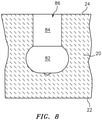
- the compartment has a first portion 82 ( FIG. 2 ) receiving the protuberance of the head and a narrower second portion 84, the second portion outboard of the first portion.
- the fastener head protuberance results from an in situ deformation.
- the fastener 50 is initially formed with the head 70 in an at least relatively non-protuberant condition and then the head 70 is expanded.
- FIG. 3 shows the fastener in this initial condition.
- the shank 52 and head 70 are hollow.
- the head 70 and shank 52 are separately formed and then joined.
- the shank 52 may be formed from threading and machining tubular stock or from rod stock with a passageway 90 drilled between ends 54 and 58.
- the head 70 may be machined or stamped in a cup-like form having a sidewall 72 with a rim 74 at one end and a transverse web 76 at the other end.
- the head 70 and shank 52 may then be attached to each other such as via welding or brazing the rim 74 to the end 58 to form a weld or braze joint.
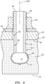
- FIG. 9 shows such a single-piece fastener 50-1 with a head 70-1 in its expanded condition relative to the shank 52-1.
- exemplary fastener materials for any of these embodiments include nickel-based superalloys.
- Exemplary alloys include IN625, IN718, IN617, Waspalloy TM , and Haynes TM 230 and 282.
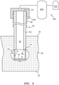
- a source 400 of pressurized fluid may then (or already) be connected to the fastener such as by attaching a fitting 402 to the shank 52, 52-1 (e.g., threading a threaded fitting or applying a quick release fitting).
- An exemplary source 400 is a high pressure gas source (e.g., having a compressor 404 and a storage tank 406).
- Other systems include hydraulic systems using liquid fluid.
- High pressure fluid is then delivered from the source 400 to the fastener 50, 50-1 (e.g., via opening a valve), pressurizing the head interior 71 and causing an at least partial plastic deformation to create the protuberance or sufficiently increase the protuberance of the head 70, 70-1 to backlock the fastener 50, 50-1 in the panel.
- the source 400 may then be disengaged (e.g., closing valve and unscrewing the fitting from the shank), leaving the head 70, 70-1 deformed and protuberant to hold the fastener 50, 50-1 against extraction.
- the fastener 50, 50-1 may be heated (via gas torch or oven (not shown)) prior to expansion and then cooled.
- Other methods of heating the fastener 50, 50-1 are induction (selectively heats the metal relative to non-conductive ceramic and CMCs) or IR to locally heat the ceramic from surface 22, which then heats the metal via conduction.
- the process may be repeated for multiple fasteners 50, 50-1 on a given panel 20.
- the panel 20 may then be installed by engaging the shank(s) 72, 72-1 with the associated holes 62 and installing the washer(s) 63 and installing/tightening the nut(s) 60.
- the shank 72, 72-1 may be held against rotation by a respective wrench or key (e.g., hex key (not shown)) holding an end portion of the shank (e.g., respectively externally faceted or internally faceted).
- the compartments 80 may be pre-formed such as by molding the ceramic over sacrificial cores having the compartment shape and then chemically or thermally removing the cores. Such cores may also be used when forming a CMC.
- the compartments 80 are machined into a precursor of the panel 20. Several possible machining techniques may be used. One group involves first drilling (drill 420 with axis of rotation 530 of FIG. 4 ) a straight blind bore of a given diameter (e.g., just large enough to pass the shank 72, 72-1 and head 70, 70-1 pre-deformation) and having an axis 520. This step may effectively form the second portion 84.
- the portion 82 may then be formed by inserting a bit (430 of FIG. 5 ) with a protuberant cutting or grinding portion 432.
- the bit 430 may be inserted with the protuberant cutting or grinding portion 432 just being accommodated by the initial bore.
- the bit may be shifted radially outward relative to the axis 520 of the bore until the narrow shaft 434 of the bit 430 contacts or nears the bore surface.
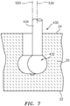
- the rotating bit 430 may then be orbited (180° completed of 360° in FIG. 7 ) around the bore axis 520 to complete the machining of the first portion 82.
- the bit 430 may then be re-centered coaxial with the bore and withdrawn, leaving the compartment 80 with the enlarged first portion 82 ( FIG. 8 ).
- the system may have one or more of several advantages.
- the head of the fastener is not exposed to the gaspath. This reduces heating of the fastener and helps maintain its integrity. In certain situations such as nozzle flaps, it may reduce RADAR or infrared (IR) signature. There may be reduced likelihood of vibrating loose. Depending upon the nature of the alternative fastener, this may also involve reduced likelihood of the fastener becoming dislodged and potentially damaging other components.
- Non-panel situations may include, for example, the mounting of vane clusters.
- first, second, and the like in the following claims is for differentiation within the claim only and does not necessarily indicate relative or absolute importance or temporal order. Similarly, the identification in a claim of one element as “first” (or the like) does not preclude such "first” element from identifying an element that is referred to as “second” (or the like) in another claim or in the description.
Landscapes
- Engineering & Computer Science (AREA)
- General Engineering & Computer Science (AREA)
- Mechanical Engineering (AREA)
- Chemical & Material Sciences (AREA)
- Combustion & Propulsion (AREA)
- Ceramic Engineering (AREA)
- Materials Engineering (AREA)
- Turbine Rotor Nozzle Sealing (AREA)
- Ceramic Products (AREA)
Abstract
Description
- The disclosure relates to aerospace propulsion. More particularly, the disclosure relates to mounting of ceramic and ceramic matrix composite (CMC) structures in engines.
- The mounting of ceramic and ceramic matrix composite parts in the hot sections of gas turbine engines has involved a variety of difficulties. These have included a number of issues involving differential thermal expansion of the metallic and non-metallic components involved.
- In some situations, metallic fasteners pass entirely through the non-metallic component. One example is as seen in
US Patent 8,607,577, of Ruberte Sanchez et al., December 17, 2013 . -
US Patent 7,832,972, of Jarmon, November 16, 2010 , discloses a system involving slotting the non-metallic panel and inserting the asymmetric heads of fasteners followed by rotating the fasteners to backlock the heads. - One aspect of the disclosure involves a method for attaching a fastener to a ceramic matrix composite or ceramic body. The method comprises: inserting a portion of the fastener into a compartment of the body, the compartment having a first portion and a second portion, the second portion outboard of and narrower than the first portion; and delivering a fluid into the fastener to expand a portion of the fastener within the compartment first portion.
- An embodiment may additionally and/or alternatively include the compartment being a blind compartment.
- A further embodiment may additionally and/or alternatively include the fastener having a threaded shank and the method comprising engaging a fluid source to the shank before the delivering and disengaging the fluid source from the shank after the delivering.
- A further embodiment may additionally and/or alternatively include heating a portion of the fastener (e.g., optionally in situ to soften to facilitate the deforming).
- A further embodiment may additionally and/or alternatively include forming the compartment by laterally shifting a rotating bit, the rotating bit having a protuberant cutting or grinding portion that forms the compartment first portion. This may be after forming an initial compartment precursor (e.g., bore) such as by drilling.
- A further embodiment may additionally and/or alternatively include the lateral shifting comprising a circular shift (e.g., after an initial radial shift).
- A further embodiment may additionally and/or alternatively include the body being a combustion panel body.
- A further embodiment may additionally and/or alternatively include manufacturing the fastener via metal injection molding or additive manufacture.
- A further embodiment may additionally and/or alternatively include the fastener expanded portion and shank being a single piece.
- Another aspect of the disclosure involves a panel assembly comprising a ceramic matrix composite or ceramic body, the body having a compartment, the compartment having a first portion and a second portion, the second portion outboard of and narrower than the first portion. A fastener has an expanded portion within the compartment first portion.
- A further embodiment may additionally and/or alternatively include the compartment being a blind compartment.
- A further embodiment may additionally and/or alternatively include the expanded portion being hollow.
- A further embodiment may additionally and/or alternatively include the expanded portion interior being continuous with a hollow portion of the shank.
- A further embodiment may additionally and/or alternatively include the body being shaped as a segment of a frustoconical shell.
- A further embodiment may additionally and/or alternatively include the fastener having a threaded shank.
- A further embodiment may additionally and/or alternatively include the panel being in combination with a mounting structure, the threaded shank passing through a hole in the mounting structure and held by a nut.
- A further embodiment may additionally and/or alternatively include a gas turbine engine comprising the panel.
- A further embodiment may additionally and/or alternatively include the panel being along a gaspath of the gas turbine engine.
- A further embodiment may additionally and/or alternatively include the panel the panel being selected from the group consisting of combustor panels, blade outer air seals, and exhaust nozzle liners.
- The details of one or more embodiments are set forth in the accompanying drawings and the description below. Other features, objects, and advantages will be apparent from the description and drawings, and from the claims.
-
-
FIG. 1 is a view of a gas turbine engine panel. -
FIG. 2 is a radial sectional view of an assembly of the panel and fasteners mounted to mounting structure in a gas turbine engine. -
FIG. 3 is a radial sectional view of the panel during securing of the fasteners in compartments in the panel. -
FIG. 4 is a radial sectional view of the panel during compartment drilling. -
FIG. 5 is a radial sectional view of the panel upon insertion of a grinding or machining bit. -
FIG. 6 is a radial sectional view of the panel after a transverse shift of the bit. -
FIG. 7 is a radial sectional view of the panel during an orbiting of the bit. -
FIG. 8 is a radial sectional view of the panel after compartment formation. -
FIG. 9 is a radial sectional view of an assembly of the panel and alternate fasteners mounted to mounting structure in a gas turbine engine. - Like reference numbers and designations in the various drawings indicate like elements.
-
FIG. 1 shows apanel 20. Theexemplary panel 20 comprises a ceramic or ceramic matrix composite (CMC) body having afirst face 22 and asecond face 24. The exemplaryfirst face 22 is a gaspath-facing face in a gas turbine engine (broadly inclusive of engines used in propulsion via thrust, other propulsive engines, industrial gas turbines, and the like). Particular applications include combustor panel liners (including as segments thereof), blade outer air seals (BOAS), exhaust nozzle flap liners, and the like. Other applications include ramjet and rocket engine use, aerodynamic thermal tiles, and the like. - In a typical combustor panel application, BOAS, or flap liner, the panel is generally a frustoconical segment with a leading end/
edge 26, a trailing end/edge 28, a first lateral end/edge 30, and a second lateral end/edge 32. In an annular combustor, there may be a longitudinal end-to-end plurality of annular lateral end-to-end arrays of such panels. - The second face 24 (backside) faces, and may in some implementations contact, an
adjacent surface 40 ofmounting structure 42. Typically, themounting structure 42 will be metallic such as a portion of an engine case or a metallic panel carrier structure. As is discussed below, thepanel 20 is mounted to the mounting structure via a fastening system. Theexemplary fasteners 50 are threaded fasteners having a shank orshaft 52 extending to anend 54 and bearing, along at least a portion, anexternal thread 56. In the installed condition, the threaded shank is received by a complementary internally-threadedmember 60 such as a nut along abackside surface 44 of the mounting structure with the shank passing through ahole 62.Various washers 63, and the like, may also be used. - The
fastener 50 has a head 70 (shown as a protuberant head) at one end of the shank captured in a compartment (e.g., a blind compartment) 80 (FIG. 1 ) open to thebackside 24 so that the shank protrudes from the backside. To backlock thehead 70, the compartment has a first portion 82 (FIG. 2 ) receiving the protuberance of the head and a narrowersecond portion 84, the second portion outboard of the first portion. As is discussed below, the fastener head protuberance results from an in situ deformation. - In an exemplary embodiment, the
fastener 50 is initially formed with thehead 70 in an at least relatively non-protuberant condition and then thehead 70 is expanded.FIG. 3 shows the fastener in this initial condition. Theshank 52 andhead 70 are hollow. In various embodiments, thehead 70 andshank 52 are separately formed and then joined. For example, theshank 52 may be formed from threading and machining tubular stock or from rod stock with apassageway 90 drilled between ends 54 and 58. Thehead 70 may be machined or stamped in a cup-like form having asidewall 72 with arim 74 at one end and atransverse web 76 at the other end. Thehead 70 andshank 52 may then be attached to each other such as via welding or brazing therim 74 to theend 58 to form a weld or braze joint. - Alternative techniques may manufacture the fastener in a single piece unitary structure such as metal injection molding (powder metallurgical (PM)), casting, or additive manufacturing.
FIG. 9 shows such a single-piece fastener 50-1 with a head 70-1 in its expanded condition relative to the shank 52-1. Exemplary fastener materials for any of these embodiments include nickel-based superalloys. Exemplary alloys include IN625, IN718, IN617, Waspalloy™, and Haynes™ 230 and 282. - The
unexpanded head 70, 70-1 may then be inserted into thecompartment 80. Asource 400 of pressurized fluid may then (or already) be connected to the fastener such as by attaching a fitting 402 to theshank 52, 52-1 (e.g., threading a threaded fitting or applying a quick release fitting). Anexemplary source 400 is a high pressure gas source (e.g., having acompressor 404 and a storage tank 406). Other systems include hydraulic systems using liquid fluid. High pressure fluid is then delivered from thesource 400 to thefastener 50, 50-1 (e.g., via opening a valve), pressurizing thehead interior 71 and causing an at least partial plastic deformation to create the protuberance or sufficiently increase the protuberance of thehead 70, 70-1 to backlock thefastener 50, 50-1 in the panel. Thesource 400 may then be disengaged (e.g., closing valve and unscrewing the fitting from the shank), leaving thehead 70, 70-1 deformed and protuberant to hold thefastener 50, 50-1 against extraction. To facilitate the plastic deformation, thefastener 50, 50-1 may be heated (via gas torch or oven (not shown)) prior to expansion and then cooled. Other methods of heating thefastener 50, 50-1 are induction (selectively heats the metal relative to non-conductive ceramic and CMCs) or IR to locally heat the ceramic fromsurface 22, which then heats the metal via conduction. - The process may be repeated for
multiple fasteners 50, 50-1 on a givenpanel 20. - The
panel 20 may then be installed by engaging the shank(s) 72, 72-1 with the associatedholes 62 and installing the washer(s) 63 and installing/tightening the nut(s) 60. During nut tightening, theshank 72, 72-1 may be held against rotation by a respective wrench or key (e.g., hex key (not shown)) holding an end portion of the shank (e.g., respectively externally faceted or internally faceted). - A number of processes may be used to form the
compartments 80. In various embodiments, the compartments may be pre-formed such as by molding the ceramic over sacrificial cores having the compartment shape and then chemically or thermally removing the cores. Such cores may also be used when forming a CMC. In another embodiment thecompartments 80 are machined into a precursor of thepanel 20. Several possible machining techniques may be used. One group involves first drilling (drill 420 with axis ofrotation 530 ofFIG. 4 ) a straight blind bore of a given diameter (e.g., just large enough to pass theshank 72, 72-1 andhead 70, 70-1 pre-deformation) and having anaxis 520. This step may effectively form thesecond portion 84. Theportion 82 may then be formed by inserting a bit (430 ofFIG. 5 ) with a protuberant cutting or grindingportion 432. Thebit 430 may be inserted with the protuberant cutting or grindingportion 432 just being accommodated by the initial bore. The bit may be shifted radially outward relative to theaxis 520 of the bore until thenarrow shaft 434 of thebit 430 contacts or nears the bore surface. Therotating bit 430 may then be orbited (180° completed of 360° inFIG. 7 ) around thebore axis 520 to complete the machining of thefirst portion 82. Thebit 430 may then be re-centered coaxial with the bore and withdrawn, leaving thecompartment 80 with the enlarged first portion 82 (FIG. 8 ). - The system may have one or more of several advantages. In several advantages, the head of the fastener is not exposed to the gaspath. This reduces heating of the fastener and helps maintain its integrity. In certain situations such as nozzle flaps, it may reduce RADAR or infrared (IR) signature. There may be reduced likelihood of vibrating loose. Depending upon the nature of the alternative fastener, this may also involve reduced likelihood of the fastener becoming dislodged and potentially damaging other components.
- Although panels are illustrated, other examples include those panels and other structures disclosed in the aforementioned Ruberte Sanchez and Jarmon patents. Non-panel situations may include, for example, the mounting of vane clusters.
- The use of "first", "second", and the like in the following claims is for differentiation within the claim only and does not necessarily indicate relative or absolute importance or temporal order. Similarly, the identification in a claim of one element as "first" (or the like) does not preclude such "first" element from identifying an element that is referred to as "second" (or the like) in another claim or in the description.
- Where a measure is given in English units followed by a parenthetical containing SI or other units, the parenthetical's units are a conversion and should not imply a degree of precision not found in the English units.
- One or more embodiments have been described. Nevertheless, it will be understood that various modifications may be made. For example, when applied to an existing baseline configuration, details of such baseline may influence details of particular implementations. Accordingly, other embodiments are within the scope of the following claims.
Claims (15)
- A panel assembly (20) comprising:a ceramic matrix composite or ceramic body (20), the body(20) having a compartment (80), the compartment (80) having a first portion (82) and a second portion (84), the second portion (84) outboard of and narrower than the first portion (82); anda fastener (50;50-1) having a hollow expanded portion (70;70-1) within the compartment first portion (82).
- The panel assembly of claim 1, therein the expanded portion (70; 70-1) has been deformed in situ within the first portion (82) of the compartment (80).
- The panel assembly of claim 2, wherein the expanded portion (70; 70-1) is too large post-deformation to pass through the second portion (84) of the compartment (80).
- The panel assembly of any preceding claim, wherein the compartment (80) is a blind compartment (80).
- The panel assembly of any preceding claim, wherein the fastener (50;50-1) has a threaded shank (52;52-1).
- The panel assembly of claim 5, in combination with a mounting structure (42), the threaded shank (52;52-1) passing through a hole (62) in the mounting structure (42) and held by a nut (60).
- The panel assembly of any of claims 1 to 5, wherein the expanded portion interior (71) is continuous with a hollow portion of a or the shank (52;52-1).
- The panel assembly of any preceding claim, wherein the body (20) is shaped as a segment of a frustoconical shell.
- A gas turbine engine comprising the panel assembly preceding claim, wherein the panel (20) is along a gaspath of the gas turbine engine.
- The gas turbine engine of claim 9, wherein the panel (20) is selected from the group consisting of combustor panels, blade outer air seals, and exhaust nozzle liners.
- A method for attaching a fastener (50;50-1) to a ceramic matrix composite or ceramic body (20), the method comprising:inserting a portion of the fastener (50;50-1) into a compartment (80) of the body (20), the compartment (80) having a first portion (82) and a second portion (84), the second portion (84) outboard of and narrower than the first portion (82); anddelivering a fluid into the fastener (50;50-1) to expand a portion (70;70-1) of the fastener (50;50-1) within the compartment first portion (82).
- The method of claim 11, wherein:the fastener (50;50-1) has a threaded shank (52;52-1), and the method comprises engaging a fluid source (400) to the shank (52) before the delivering and disengaging the fluid source from the shank (52) after the delivering; and/orthe method further comprises heating a portion (70;70-1) of the fastener (50;50-1).
- The method of claim 11 or 12, further comprising forming the compartment (80) by laterally shifting a rotating bit (430), the rotating bit (430) having a protuberant cutting or grinding portion (432) that forms the compartment first portion (82), wherein, optionally:forming the compartment (80) further comprises forming an initial bore; and/orthe lateral shifting comprises a circular shift.
- The method of any of claims 11 to 13, wherein the body (20) is a combustor panel body.
- The method of any of claims 11 to 14, further comprising manufacturing the fastener (50;50-1) via metal injection molding or additive manufacture.
Applications Claiming Priority (2)
| Application Number | Priority Date | Filing Date | Title |
|---|---|---|---|
| US15/140,911 US10234141B2 (en) | 2016-04-28 | 2016-04-28 | Ceramic and ceramic matrix composite attachment methods and systems |
| EP17168819.5A EP3244029B1 (en) | 2016-04-28 | 2017-04-28 | Ceramic and ceramic matrix composite attachment method and system |
Related Parent Applications (1)
| Application Number | Title | Priority Date | Filing Date |
|---|---|---|---|
| EP17168819.5A Division EP3244029B1 (en) | 2016-04-28 | 2017-04-28 | Ceramic and ceramic matrix composite attachment method and system |
Publications (2)
| Publication Number | Publication Date |
|---|---|
| EP3971395A1 true EP3971395A1 (en) | 2022-03-23 |
| EP3971395B1 EP3971395B1 (en) | 2025-02-12 |
Family
ID=58644968
Family Applications (2)
| Application Number | Title | Priority Date | Filing Date |
|---|---|---|---|
| EP21208242.4A Active EP3971395B1 (en) | 2016-04-28 | 2017-04-28 | Panel assembly and method for forming the same |
| EP17168819.5A Active EP3244029B1 (en) | 2016-04-28 | 2017-04-28 | Ceramic and ceramic matrix composite attachment method and system |
Family Applications After (1)
| Application Number | Title | Priority Date | Filing Date |
|---|---|---|---|
| EP17168819.5A Active EP3244029B1 (en) | 2016-04-28 | 2017-04-28 | Ceramic and ceramic matrix composite attachment method and system |
Country Status (2)
| Country | Link |
|---|---|
| US (1) | US10234141B2 (en) |
| EP (2) | EP3971395B1 (en) |
Families Citing this family (3)
| Publication number | Priority date | Publication date | Assignee | Title |
|---|---|---|---|---|
| US10605087B2 (en) * | 2017-12-14 | 2020-03-31 | United Technologies Corporation | CMC component with flowpath surface ribs |
| US12163547B2 (en) | 2021-03-18 | 2024-12-10 | General Electric Company | Ceramic matrix composite fastener |
| US12578093B2 (en) | 2024-03-14 | 2026-03-17 | General Electric Company | Gas turbine engine combustor |
Citations (5)
| Publication number | Priority date | Publication date | Assignee | Title |
|---|---|---|---|---|
| EP0298892A1 (en) * | 1987-07-08 | 1989-01-11 | United Technologies Corporation | Locked threaded insert for high stress application |
| US20090226279A1 (en) * | 2008-03-05 | 2009-09-10 | Jarmon David C | Internal pocket fastener system for ceramic matrix composites |
| US8607577B2 (en) | 2009-11-24 | 2013-12-17 | United Technologies Corporation | Attaching ceramic matrix composite to high temperature gas turbine structure |
| EP2682245A2 (en) * | 2012-07-05 | 2014-01-08 | General Electric Company | Apparatus for manufacturing a flange composite component and methods of manufacturing the same |
| WO2014187659A1 (en) * | 2013-05-21 | 2014-11-27 | Siemens Aktiengesellschaft | Heat shield tile for a heat shield of a combustion chamber |
Family Cites Families (23)
| Publication number | Priority date | Publication date | Assignee | Title |
|---|---|---|---|---|
| US1956623A (en) * | 1932-04-14 | 1934-05-01 | Newhall Henry B Corp | Spring toggle |
| US2013503A (en) * | 1934-12-26 | 1935-09-03 | Henry W Pleister | Spring toggle bolt |
| US2061634A (en) * | 1935-10-07 | 1936-11-24 | Diamond Expansion Bolt Co | Spring toggle bolt |
| US2543063A (en) * | 1941-04-16 | 1951-02-27 | George D Rogers | Method of hydraulically expanding hollow rivets |
| US2562721A (en) * | 1941-08-13 | 1951-07-31 | United Air Lines Inc | Method of hydraulically expanding hollow rivets |
| US2492605A (en) * | 1941-11-10 | 1949-12-27 | United Air Lines Inc | Hydraulically expansible hollow rivet |
| US2342732A (en) * | 1942-01-26 | 1944-02-29 | Gudmundsen Stratton Lab Inc | Rivet |
| US2359629A (en) * | 1943-01-06 | 1944-10-03 | Us Rubber Co | Rivet |
| US2562724A (en) * | 1943-04-02 | 1951-07-31 | United Air Lines Inc | Hydraulically expanding hollow rivet |
| US2421769A (en) * | 1943-10-09 | 1947-06-10 | Richard C Wolfe | Method of expanding hollow fasteners |
| US2535079A (en) * | 1944-05-02 | 1950-12-26 | United Air Lines Inc | Method of upsetting a hollow rivet |
| US2445803A (en) * | 1945-10-22 | 1948-07-27 | George D Rogers | Method of expanding hydraulic rivets by increments of internal pressure |
| US3520225A (en) * | 1968-02-12 | 1970-07-14 | Huck Mfg Co | Hydraulic drive pin rivet |
| US4609136A (en) * | 1985-08-15 | 1986-09-02 | Nifco Inc. | Rivet driver |
| US6301766B1 (en) * | 1998-01-12 | 2001-10-16 | Tempress Technologies, Inc. | Method for metal working using high pressure fluid pulses |
| US20080080949A1 (en) * | 2006-09-18 | 2008-04-03 | Jinn-Yi Deng | Spring toggle |
| US7926286B2 (en) * | 2006-09-26 | 2011-04-19 | Pratt & Whitney Canada Corp. | Heat shield for a fuel manifold |
| FR2909748B1 (en) * | 2006-12-07 | 2009-07-10 | Snecma Sa | BOTTOM BOTTOM, METHOD OF MAKING SAME, COMBUSTION CHAMBER COMPRISING SAME, AND TURBOJET ENGINE |
| US8800293B2 (en) | 2007-07-10 | 2014-08-12 | United Technologies Corporation | Floatwell panel assemblies and related systems |
| US8256223B2 (en) | 2007-10-16 | 2012-09-04 | United Technologies Corporation | Ceramic combustor liner panel for a gas turbine engine |
| US9003633B1 (en) * | 2011-08-19 | 2015-04-14 | Agostino Difante | Concrete anchor bolt fastener and tool and method for installing |
| FR2986856B1 (en) * | 2012-02-15 | 2018-05-04 | Safran Aircraft Engines | DEVICE FOR INJECTING AIR AND FUEL FOR A COMBUSTION CHAMBER OF A TURBOMACHINE |
| US20160351085A1 (en) * | 2015-05-29 | 2016-12-01 | Milspray, LLC | Recessed label mount |
-
2016
- 2016-04-28 US US15/140,911 patent/US10234141B2/en active Active
-
2017
- 2017-04-28 EP EP21208242.4A patent/EP3971395B1/en active Active
- 2017-04-28 EP EP17168819.5A patent/EP3244029B1/en active Active
Patent Citations (6)
| Publication number | Priority date | Publication date | Assignee | Title |
|---|---|---|---|---|
| EP0298892A1 (en) * | 1987-07-08 | 1989-01-11 | United Technologies Corporation | Locked threaded insert for high stress application |
| US20090226279A1 (en) * | 2008-03-05 | 2009-09-10 | Jarmon David C | Internal pocket fastener system for ceramic matrix composites |
| US7832972B2 (en) | 2008-03-05 | 2010-11-16 | United Technologies Corporation | Internal pocket fastener system for ceramic matrix composites |
| US8607577B2 (en) | 2009-11-24 | 2013-12-17 | United Technologies Corporation | Attaching ceramic matrix composite to high temperature gas turbine structure |
| EP2682245A2 (en) * | 2012-07-05 | 2014-01-08 | General Electric Company | Apparatus for manufacturing a flange composite component and methods of manufacturing the same |
| WO2014187659A1 (en) * | 2013-05-21 | 2014-11-27 | Siemens Aktiengesellschaft | Heat shield tile for a heat shield of a combustion chamber |
Also Published As
| Publication number | Publication date |
|---|---|
| EP3971395B1 (en) | 2025-02-12 |
| EP3244029B1 (en) | 2021-11-17 |
| US20170314785A1 (en) | 2017-11-02 |
| EP3244029A1 (en) | 2017-11-15 |
| US10234141B2 (en) | 2019-03-19 |
Similar Documents
| Publication | Publication Date | Title |
|---|---|---|
| EP3330553B1 (en) | Fastener | |
| US9845692B2 (en) | Turbine component connection with thermally stress-free fastener | |
| US8607577B2 (en) | Attaching ceramic matrix composite to high temperature gas turbine structure | |
| EP3022424B1 (en) | Gas turbine engine ceramic panel assembly and method of manufacturing a gas turbine engine ceramic panel assembly | |
| EP1535692B1 (en) | A method of fabricating or repairing an assembly | |
| EP3971395B1 (en) | Panel assembly and method for forming the same | |
| US10273830B2 (en) | Replacing an aperture with an annular bushing in a composite laminated composite component | |
| EP3708811B1 (en) | Engine exhaust skin connection system | |
| JPH09170497A (en) | Repairable liner | |
| WO2016077071A2 (en) | Masking plug for cold spray repair at counterbore hole | |
| EP3034891A1 (en) | Ceramic bolt for exhaust panel | |
| US8850823B2 (en) | Integrated aero-engine flowpath structure | |
| EP3299579B1 (en) | Method involving friction plug welding a flange | |
| WO2017074407A1 (en) | System and method for attaching a non-metal component to a metal component | |
| EP2540988B1 (en) | Blade outer air seal with a plug assembly and method | |
| EP3260739B1 (en) | Low-cost epicyclic gear carrier and method of making the same | |
| EP2961961B1 (en) | Method of fabricating an airfoil cluster and corresponding airfoil cluster | |
| EP3640544B1 (en) | Combustor liner panel attachment assembly for gas turbine engine | |
| EP3795902B1 (en) | Support structure for combustor components and method of using same | |
| JP4509085B2 (en) | Coating method and apparatus | |
| US11415163B2 (en) | Expanding retention locking plug | |
| CN102650221A (en) | Explosion-welded gas turbine shroud and a process of forming an explosion-welded gas turbine | |
| EP2960431B1 (en) | Systems and methods for repairing a surface of damaged metal components |
Legal Events
| Date | Code | Title | Description |
|---|---|---|---|
| PUAI | Public reference made under article 153(3) epc to a published international application that has entered the european phase |
Free format text: ORIGINAL CODE: 0009012 |
|
| STAA | Information on the status of an ep patent application or granted ep patent |
Free format text: STATUS: THE APPLICATION HAS BEEN PUBLISHED |
|
| AC | Divisional application: reference to earlier application |
Ref document number: 3244029 Country of ref document: EP Kind code of ref document: P |
|
| AK | Designated contracting states |
Kind code of ref document: A1 Designated state(s): AL AT BE BG CH CY CZ DE DK EE ES FI FR GB GR HR HU IE IS IT LI LT LU LV MC MK MT NL NO PL PT RO RS SE SI SK SM TR |
|
| STAA | Information on the status of an ep patent application or granted ep patent |
Free format text: STATUS: REQUEST FOR EXAMINATION WAS MADE |
|
| 17P | Request for examination filed |
Effective date: 20220527 |
|
| RBV | Designated contracting states (corrected) |
Designated state(s): AL AT BE BG CH CY CZ DE DK EE ES FI FR GB GR HR HU IE IS IT LI LT LU LV MC MK MT NL NO PL PT RO RS SE SI SK SM TR |
|
| STAA | Information on the status of an ep patent application or granted ep patent |
Free format text: STATUS: EXAMINATION IS IN PROGRESS |
|
| 17Q | First examination report despatched |
Effective date: 20230323 |
|
| RAP3 | Party data changed (applicant data changed or rights of an application transferred) |
Owner name: RTX CORPORATION |
|
| GRAP | Despatch of communication of intention to grant a patent |
Free format text: ORIGINAL CODE: EPIDOSNIGR1 |
|
| STAA | Information on the status of an ep patent application or granted ep patent |
Free format text: STATUS: GRANT OF PATENT IS INTENDED |
|
| INTG | Intention to grant announced |
Effective date: 20240906 |
|
| GRAS | Grant fee paid |
Free format text: ORIGINAL CODE: EPIDOSNIGR3 |
|
| GRAA | (expected) grant |
Free format text: ORIGINAL CODE: 0009210 |
|
| STAA | Information on the status of an ep patent application or granted ep patent |
Free format text: STATUS: THE PATENT HAS BEEN GRANTED |
|
| AC | Divisional application: reference to earlier application |
Ref document number: 3244029 Country of ref document: EP Kind code of ref document: P |
|
| AK | Designated contracting states |
Kind code of ref document: B1 Designated state(s): AL AT BE BG CH CY CZ DE DK EE ES FI FR GB GR HR HU IE IS IT LI LT LU LV MC MK MT NL NO PL PT RO RS SE SI SK SM TR |
|
| REG | Reference to a national code |
Ref country code: GB Ref legal event code: FG4D |
|
| REG | Reference to a national code |
Ref country code: CH Ref legal event code: EP |
|
| REG | Reference to a national code |
Ref country code: DE Ref legal event code: R096 Ref document number: 602017087796 Country of ref document: DE |
|
| REG | Reference to a national code |
Ref country code: IE Ref legal event code: FG4D |
|
| REG | Reference to a national code |
Ref country code: NL Ref legal event code: MP Effective date: 20250212 |
|
| PG25 | Lapsed in a contracting state [announced via postgrant information from national office to epo] |
Ref country code: RS Free format text: LAPSE BECAUSE OF FAILURE TO SUBMIT A TRANSLATION OF THE DESCRIPTION OR TO PAY THE FEE WITHIN THE PRESCRIBED TIME-LIMIT Effective date: 20250512 |
|
| PG25 | Lapsed in a contracting state [announced via postgrant information from national office to epo] |
Ref country code: FI Free format text: LAPSE BECAUSE OF FAILURE TO SUBMIT A TRANSLATION OF THE DESCRIPTION OR TO PAY THE FEE WITHIN THE PRESCRIBED TIME-LIMIT Effective date: 20250212 |
|
| PG25 | Lapsed in a contracting state [announced via postgrant information from national office to epo] |
Ref country code: PL Free format text: LAPSE BECAUSE OF FAILURE TO SUBMIT A TRANSLATION OF THE DESCRIPTION OR TO PAY THE FEE WITHIN THE PRESCRIBED TIME-LIMIT Effective date: 20250212 |
|
| PGFP | Annual fee paid to national office [announced via postgrant information from national office to epo] |
Ref country code: DE Payment date: 20250319 Year of fee payment: 9 |
|
| PG25 | Lapsed in a contracting state [announced via postgrant information from national office to epo] |
Ref country code: ES Free format text: LAPSE BECAUSE OF FAILURE TO SUBMIT A TRANSLATION OF THE DESCRIPTION OR TO PAY THE FEE WITHIN THE PRESCRIBED TIME-LIMIT Effective date: 20250212 |
|
| REG | Reference to a national code |
Ref country code: LT Ref legal event code: MG9D |
|
| PG25 | Lapsed in a contracting state [announced via postgrant information from national office to epo] |
Ref country code: NO Free format text: LAPSE BECAUSE OF FAILURE TO SUBMIT A TRANSLATION OF THE DESCRIPTION OR TO PAY THE FEE WITHIN THE PRESCRIBED TIME-LIMIT Effective date: 20250512 Ref country code: IS Free format text: LAPSE BECAUSE OF FAILURE TO SUBMIT A TRANSLATION OF THE DESCRIPTION OR TO PAY THE FEE WITHIN THE PRESCRIBED TIME-LIMIT Effective date: 20250612 |
|
| PG25 | Lapsed in a contracting state [announced via postgrant information from national office to epo] |
Ref country code: NL Free format text: LAPSE BECAUSE OF FAILURE TO SUBMIT A TRANSLATION OF THE DESCRIPTION OR TO PAY THE FEE WITHIN THE PRESCRIBED TIME-LIMIT Effective date: 20250212 |
|
| PG25 | Lapsed in a contracting state [announced via postgrant information from national office to epo] |
Ref country code: HR Free format text: LAPSE BECAUSE OF FAILURE TO SUBMIT A TRANSLATION OF THE DESCRIPTION OR TO PAY THE FEE WITHIN THE PRESCRIBED TIME-LIMIT Effective date: 20250212 |
|
| PG25 | Lapsed in a contracting state [announced via postgrant information from national office to epo] |
Ref country code: LV Free format text: LAPSE BECAUSE OF FAILURE TO SUBMIT A TRANSLATION OF THE DESCRIPTION OR TO PAY THE FEE WITHIN THE PRESCRIBED TIME-LIMIT Effective date: 20250212 Ref country code: PT Free format text: LAPSE BECAUSE OF FAILURE TO SUBMIT A TRANSLATION OF THE DESCRIPTION OR TO PAY THE FEE WITHIN THE PRESCRIBED TIME-LIMIT Effective date: 20250612 |
|
| PG25 | Lapsed in a contracting state [announced via postgrant information from national office to epo] |
Ref country code: GR Free format text: LAPSE BECAUSE OF FAILURE TO SUBMIT A TRANSLATION OF THE DESCRIPTION OR TO PAY THE FEE WITHIN THE PRESCRIBED TIME-LIMIT Effective date: 20250513 Ref country code: BG Free format text: LAPSE BECAUSE OF FAILURE TO SUBMIT A TRANSLATION OF THE DESCRIPTION OR TO PAY THE FEE WITHIN THE PRESCRIBED TIME-LIMIT Effective date: 20250212 |
|
| REG | Reference to a national code |
Ref country code: AT Ref legal event code: MK05 Ref document number: 1766211 Country of ref document: AT Kind code of ref document: T Effective date: 20250212 |
|
| PG25 | Lapsed in a contracting state [announced via postgrant information from national office to epo] |
Ref country code: SE Free format text: LAPSE BECAUSE OF FAILURE TO SUBMIT A TRANSLATION OF THE DESCRIPTION OR TO PAY THE FEE WITHIN THE PRESCRIBED TIME-LIMIT Effective date: 20250212 |
|
| PG25 | Lapsed in a contracting state [announced via postgrant information from national office to epo] |
Ref country code: SM Free format text: LAPSE BECAUSE OF FAILURE TO SUBMIT A TRANSLATION OF THE DESCRIPTION OR TO PAY THE FEE WITHIN THE PRESCRIBED TIME-LIMIT Effective date: 20250212 |
|
| PG25 | Lapsed in a contracting state [announced via postgrant information from national office to epo] |
Ref country code: DK Free format text: LAPSE BECAUSE OF FAILURE TO SUBMIT A TRANSLATION OF THE DESCRIPTION OR TO PAY THE FEE WITHIN THE PRESCRIBED TIME-LIMIT Effective date: 20250212 |
|
| PG25 | Lapsed in a contracting state [announced via postgrant information from national office to epo] |
Ref country code: IT Free format text: LAPSE BECAUSE OF FAILURE TO SUBMIT A TRANSLATION OF THE DESCRIPTION OR TO PAY THE FEE WITHIN THE PRESCRIBED TIME-LIMIT Effective date: 20250212 |
|
| PG25 | Lapsed in a contracting state [announced via postgrant information from national office to epo] |
Ref country code: AT Free format text: LAPSE BECAUSE OF FAILURE TO SUBMIT A TRANSLATION OF THE DESCRIPTION OR TO PAY THE FEE WITHIN THE PRESCRIBED TIME-LIMIT Effective date: 20250212 |
|
| PG25 | Lapsed in a contracting state [announced via postgrant information from national office to epo] |
Ref country code: CZ Free format text: LAPSE BECAUSE OF FAILURE TO SUBMIT A TRANSLATION OF THE DESCRIPTION OR TO PAY THE FEE WITHIN THE PRESCRIBED TIME-LIMIT Effective date: 20250212 Ref country code: EE Free format text: LAPSE BECAUSE OF FAILURE TO SUBMIT A TRANSLATION OF THE DESCRIPTION OR TO PAY THE FEE WITHIN THE PRESCRIBED TIME-LIMIT Effective date: 20250212 |
|
| PG25 | Lapsed in a contracting state [announced via postgrant information from national office to epo] |
Ref country code: RO Free format text: LAPSE BECAUSE OF FAILURE TO SUBMIT A TRANSLATION OF THE DESCRIPTION OR TO PAY THE FEE WITHIN THE PRESCRIBED TIME-LIMIT Effective date: 20250212 |
|
| PG25 | Lapsed in a contracting state [announced via postgrant information from national office to epo] |
Ref country code: SK Free format text: LAPSE BECAUSE OF FAILURE TO SUBMIT A TRANSLATION OF THE DESCRIPTION OR TO PAY THE FEE WITHIN THE PRESCRIBED TIME-LIMIT Effective date: 20250212 |
|
| REG | Reference to a national code |
Ref country code: DE Ref legal event code: R097 Ref document number: 602017087796 Country of ref document: DE |
|
| REG | Reference to a national code |
Ref country code: CH Ref legal event code: H13 Free format text: ST27 STATUS EVENT CODE: U-0-0-H10-H13 (AS PROVIDED BY THE NATIONAL OFFICE) Effective date: 20251125 |
|
| PG25 | Lapsed in a contracting state [announced via postgrant information from national office to epo] |
Ref country code: LU Free format text: LAPSE BECAUSE OF NON-PAYMENT OF DUE FEES Effective date: 20250428 |
|
| PLBE | No opposition filed within time limit |
Free format text: ORIGINAL CODE: 0009261 |
|
| STAA | Information on the status of an ep patent application or granted ep patent |
Free format text: STATUS: NO OPPOSITION FILED WITHIN TIME LIMIT |
|
| PG25 | Lapsed in a contracting state [announced via postgrant information from national office to epo] |
Ref country code: MC Free format text: LAPSE BECAUSE OF FAILURE TO SUBMIT A TRANSLATION OF THE DESCRIPTION OR TO PAY THE FEE WITHIN THE PRESCRIBED TIME-LIMIT Effective date: 20250212 |
|
| REG | Reference to a national code |
Ref country code: BE Ref legal event code: MM Effective date: 20250430 |
|
| PG25 | Lapsed in a contracting state [announced via postgrant information from national office to epo] |
Ref country code: BE Free format text: LAPSE BECAUSE OF NON-PAYMENT OF DUE FEES Effective date: 20250430 |
|
| PG25 | Lapsed in a contracting state [announced via postgrant information from national office to epo] |
Ref country code: CH Free format text: LAPSE BECAUSE OF NON-PAYMENT OF DUE FEES Effective date: 20250430 |
|
| 26N | No opposition filed |
Effective date: 20251113 |
|
| PGFP | Annual fee paid to national office [announced via postgrant information from national office to epo] |
Ref country code: GB Payment date: 20260319 Year of fee payment: 10 |
|
| PG25 | Lapsed in a contracting state [announced via postgrant information from national office to epo] |
Ref country code: IE Free format text: LAPSE BECAUSE OF NON-PAYMENT OF DUE FEES Effective date: 20250428 |
|
| PGFP | Annual fee paid to national office [announced via postgrant information from national office to epo] |
Ref country code: FR Payment date: 20260319 Year of fee payment: 10 |