EP3971159A1 - Method for decomposing phenol-based by-product - Google Patents
Method for decomposing phenol-based by-product Download PDFInfo
- Publication number
- EP3971159A1 EP3971159A1 EP21819014.8A EP21819014A EP3971159A1 EP 3971159 A1 EP3971159 A1 EP 3971159A1 EP 21819014 A EP21819014 A EP 21819014A EP 3971159 A1 EP3971159 A1 EP 3971159A1
- Authority
- EP
- European Patent Office
- Prior art keywords
- stream
- phenol
- product
- decomposition
- discharge stream
- Prior art date
- Legal status (The legal status is an assumption and is not a legal conclusion. Google has not performed a legal analysis and makes no representation as to the accuracy of the status listed.)
- Granted
Links
Images

Classifications
-
- C—CHEMISTRY; METALLURGY
- C07—ORGANIC CHEMISTRY
- C07C—ACYCLIC OR CARBOCYCLIC COMPOUNDS
- C07C37/00—Preparation of compounds having hydroxy or O-metal groups bound to a carbon atom of a six-membered aromatic ring
- C07C37/08—Preparation of compounds having hydroxy or O-metal groups bound to a carbon atom of a six-membered aromatic ring by decomposition of hydroperoxides, e.g. cumene hydroperoxide
-
- C—CHEMISTRY; METALLURGY
- C07—ORGANIC CHEMISTRY
- C07C—ACYCLIC OR CARBOCYCLIC COMPOUNDS
- C07C37/00—Preparation of compounds having hydroxy or O-metal groups bound to a carbon atom of a six-membered aromatic ring
- C07C37/68—Purification; separation; Use of additives, e.g. for stabilisation
- C07C37/70—Purification; separation; Use of additives, e.g. for stabilisation by physical treatment
- C07C37/74—Purification; separation; Use of additives, e.g. for stabilisation by physical treatment by distillation
-
- C—CHEMISTRY; METALLURGY
- C07—ORGANIC CHEMISTRY
- C07C—ACYCLIC OR CARBOCYCLIC COMPOUNDS
- C07C1/00—Preparation of hydrocarbons from one or more compounds, none of them being a hydrocarbon
- C07C1/20—Preparation of hydrocarbons from one or more compounds, none of them being a hydrocarbon starting from organic compounds containing only oxygen atoms as heteroatoms
-
- C—CHEMISTRY; METALLURGY
- C07—ORGANIC CHEMISTRY
- C07C—ACYCLIC OR CARBOCYCLIC COMPOUNDS
- C07C15/00—Cyclic hydrocarbons containing only six-membered aromatic rings as cyclic parts
- C07C15/02—Monocyclic hydrocarbons
- C07C15/085—Isopropylbenzene
-
- C—CHEMISTRY; METALLURGY
- C07—ORGANIC CHEMISTRY
- C07C—ACYCLIC OR CARBOCYCLIC COMPOUNDS
- C07C15/00—Cyclic hydrocarbons containing only six-membered aromatic rings as cyclic parts
- C07C15/40—Cyclic hydrocarbons containing only six-membered aromatic rings as cyclic parts substituted by unsaturated carbon radicals
- C07C15/42—Cyclic hydrocarbons containing only six-membered aromatic rings as cyclic parts substituted by unsaturated carbon radicals monocyclic
- C07C15/44—Cyclic hydrocarbons containing only six-membered aromatic rings as cyclic parts substituted by unsaturated carbon radicals monocyclic the hydrocarbon substituent containing a carbon-to-carbon double bond
- C07C15/46—Styrene; Ring-alkylated styrenes
-
- C—CHEMISTRY; METALLURGY
- C07—ORGANIC CHEMISTRY
- C07C—ACYCLIC OR CARBOCYCLIC COMPOUNDS
- C07C37/00—Preparation of compounds having hydroxy or O-metal groups bound to a carbon atom of a six-membered aromatic ring
- C07C37/50—Preparation of compounds having hydroxy or O-metal groups bound to a carbon atom of a six-membered aromatic ring by reactions decreasing the number of carbon atoms
-
- C—CHEMISTRY; METALLURGY
- C07—ORGANIC CHEMISTRY
- C07C—ACYCLIC OR CARBOCYCLIC COMPOUNDS
- C07C37/00—Preparation of compounds having hydroxy or O-metal groups bound to a carbon atom of a six-membered aromatic ring
- C07C37/50—Preparation of compounds having hydroxy or O-metal groups bound to a carbon atom of a six-membered aromatic ring by reactions decreasing the number of carbon atoms
- C07C37/52—Preparation of compounds having hydroxy or O-metal groups bound to a carbon atom of a six-membered aromatic ring by reactions decreasing the number of carbon atoms by splitting polyaromatic compounds, e.g. polyphenolalkanes
-
- C—CHEMISTRY; METALLURGY
- C07—ORGANIC CHEMISTRY
- C07C—ACYCLIC OR CARBOCYCLIC COMPOUNDS
- C07C37/00—Preparation of compounds having hydroxy or O-metal groups bound to a carbon atom of a six-membered aromatic ring
- C07C37/50—Preparation of compounds having hydroxy or O-metal groups bound to a carbon atom of a six-membered aromatic ring by reactions decreasing the number of carbon atoms
- C07C37/56—Preparation of compounds having hydroxy or O-metal groups bound to a carbon atom of a six-membered aromatic ring by reactions decreasing the number of carbon atoms by replacing a carboxyl or aldehyde group by a hydroxy group
-
- C—CHEMISTRY; METALLURGY
- C07—ORGANIC CHEMISTRY
- C07C—ACYCLIC OR CARBOCYCLIC COMPOUNDS
- C07C37/00—Preparation of compounds having hydroxy or O-metal groups bound to a carbon atom of a six-membered aromatic ring
- C07C37/68—Purification; separation; Use of additives, e.g. for stabilisation
- C07C37/70—Purification; separation; Use of additives, e.g. for stabilisation by physical treatment
- C07C37/72—Purification; separation; Use of additives, e.g. for stabilisation by physical treatment by liquid-liquid treatment
-
- C—CHEMISTRY; METALLURGY
- C07—ORGANIC CHEMISTRY
- C07C—ACYCLIC OR CARBOCYCLIC COMPOUNDS
- C07C37/00—Preparation of compounds having hydroxy or O-metal groups bound to a carbon atom of a six-membered aromatic ring
- C07C37/68—Purification; separation; Use of additives, e.g. for stabilisation
- C07C37/86—Purification; separation; Use of additives, e.g. for stabilisation by treatment giving rise to a chemical modification
-
- C—CHEMISTRY; METALLURGY
- C07—ORGANIC CHEMISTRY
- C07C—ACYCLIC OR CARBOCYCLIC COMPOUNDS
- C07C39/00—Compounds having at least one hydroxy or O-metal group bound to a carbon atom of a six-membered aromatic ring
- C07C39/02—Compounds having at least one hydroxy or O-metal group bound to a carbon atom of a six-membered aromatic ring monocyclic with no unsaturation outside the aromatic ring
- C07C39/04—Phenol
-
- C—CHEMISTRY; METALLURGY
- C07—ORGANIC CHEMISTRY
- C07C—ACYCLIC OR CARBOCYCLIC COMPOUNDS
- C07C45/00—Preparation of compounds having >C = O groups bound only to carbon or hydrogen atoms; Preparation of chelates of such compounds
- C07C45/51—Preparation of compounds having >C = O groups bound only to carbon or hydrogen atoms; Preparation of chelates of such compounds by pyrolysis, rearrangement or decomposition
- C07C45/517—Preparation of compounds having >C = O groups bound only to carbon or hydrogen atoms; Preparation of chelates of such compounds by pyrolysis, rearrangement or decomposition involving transformation of peroxy-compounds to >C = O groups
-
- C—CHEMISTRY; METALLURGY
- C07—ORGANIC CHEMISTRY
- C07C—ACYCLIC OR CARBOCYCLIC COMPOUNDS
- C07C45/00—Preparation of compounds having >C = O groups bound only to carbon or hydrogen atoms; Preparation of chelates of such compounds
- C07C45/78—Separation; Purification; Stabilisation; Use of additives
- C07C45/80—Separation; Purification; Stabilisation; Use of additives by liquid-liquid treatment
-
- C—CHEMISTRY; METALLURGY
- C07—ORGANIC CHEMISTRY
- C07C—ACYCLIC OR CARBOCYCLIC COMPOUNDS
- C07C45/00—Preparation of compounds having >C = O groups bound only to carbon or hydrogen atoms; Preparation of chelates of such compounds
- C07C45/78—Separation; Purification; Stabilisation; Use of additives
- C07C45/81—Separation; Purification; Stabilisation; Use of additives by change in the physical state, e.g. crystallisation
- C07C45/82—Separation; Purification; Stabilisation; Use of additives by change in the physical state, e.g. crystallisation by distillation
-
- C—CHEMISTRY; METALLURGY
- C07—ORGANIC CHEMISTRY
- C07C—ACYCLIC OR CARBOCYCLIC COMPOUNDS
- C07C7/00—Purification; Separation; Use of additives
- C07C7/04—Purification; Separation; Use of additives by distillation
-
- F—MECHANICAL ENGINEERING; LIGHTING; HEATING; WEAPONS; BLASTING
- F28—HEAT EXCHANGE IN GENERAL
- F28D—HEAT-EXCHANGE APPARATUS, NOT PROVIDED FOR IN ANOTHER SUBCLASS, IN WHICH THE HEAT-EXCHANGE MEDIA DO NOT COME INTO DIRECT CONTACT
- F28D21/00—Heat-exchange apparatus not covered by any of the groups F28D1/00 - F28D20/00
- F28D21/0001—Recuperative heat exchangers
-
- F—MECHANICAL ENGINEERING; LIGHTING; HEATING; WEAPONS; BLASTING
- F28—HEAT EXCHANGE IN GENERAL
- F28D—HEAT-EXCHANGE APPARATUS, NOT PROVIDED FOR IN ANOTHER SUBCLASS, IN WHICH THE HEAT-EXCHANGE MEDIA DO NOT COME INTO DIRECT CONTACT
- F28D21/00—Heat-exchange apparatus not covered by any of the groups F28D1/00 - F28D20/00
- F28D2021/0019—Other heat exchangers for particular applications; Heat exchange systems not otherwise provided for
- F28D2021/0022—Other heat exchangers for particular applications; Heat exchange systems not otherwise provided for for chemical reactors
Definitions
- the present invention relates to a method of decomposing phenol-based by-product, and more particularly, to a method of decomposing phenol-based by-product, which may effectively separate effective components from phenol-based by-product and also, may reduce an amount of energy used.
- Hock process About 95% of phenols used around the world are generally produced by a Hock process.
- the Hock process is carried out by three steps of: (1) alkylating benzene by propylene to form cumene, (2) binding the cumene with oxygen to oxidize cumene to cumene hydroperoxide (CHP), and (3) decomposing cumene hydroperoxide into phenol and acetone by an acid decomposition reaction in the presence of an acid catalyst.
- CHP cumene hydroperoxide
- step (2) of oxidizing cumene by-product such as acetophenone (AP), dimethyl benzyl alcohol (DMBA), dicumyl peroxide (DCP), and dicumene (DC) are produced, in addition to cumene hydroperoxide.
- AP acetophenone
- DMBA dimethyl benzyl alcohol
- DCP dicumyl peroxide
- DC dicumene
- step (3) of acid decomposition reaction of cumene hydroperoxide hydroxy acetone (HA), 2-methylbenzofuran (2-MBF), ⁇ -methylstyrene (AMS), mesityl oxide (MO), an ⁇ -methylstyrene dimer (AMS dimer), cumylphenol (CP), and the like are produced as by-product, in addition to phenol and acetone.
- HA hydroxy acetone
- AMS ⁇ -methylstyrene
- MO mesityl oxide
- AMS dimer ⁇ -methylstyrene dimer
- CP cumylphenol
- the product stream is introduced to a separate separation device, in which an acetone-based mixture including unreacted cumene, acetone, ⁇ -methylstyrene, hydroxyacetone, and the like is separated in the tower top of the separation device and a phenol-based mixture including phenol, a part of ⁇ -methylstyrene and 2-methylbenzofuran, other by-products, and the like is separated in the tower bottom of the separation device.
- the phenol-based mixture separated from the tower bottom of the separation device is introduced to a phenol column, in which phenol is separated in the tower top of the phenol column and phenol-based by-product such as dicumyl peroxide, cumylphenol, ⁇ -methylstyrene dimer, and tar are separated in the tower bottom of the phenol column.
- phenol-based by-product such as dicumyl peroxide, cumylphenol, ⁇ -methylstyrene dimer, and tar are separated in the tower bottom of the phenol column.
- a process of producing bisphenol A is a process of condensing phenol and acetone produced from the Hock process in the presence of an acidic catalyst or a cation exchange resin to produce bisphenol A.
- An object of the present invention is to provide a method which decomposes phenol-based by-product to obtain effective components and uses a side discharge stream from a decomposition device to reuse heat from the side discharge stream from the decomposition device in the process, thereby reducing energy.
- a method of decomposing phenol-based by-product includes: introducing a phenol-based by-product stream, a first stream of a side discharge stream from a decomposition device, and a process water stream to a mixing device and mixing the streams; introducing a discharge stream from the mixing device to a layer separation device to phase-separate the stream into an oil phase and an aqueous phase; passing an oil stream discharged from the layer separation device through any one or more of a first heat exchanger and a second heat exchanger and introducing the stream to the decomposition device to carry out decomposition; and supplying the first stream of the side discharge stream from the decomposition device to the mixing device, forming a mixed stream of a second stream of the side discharge stream with a lower discharge stream and discharging the mixed stream, and recovering effective components from an upper discharge stream.
- a side discharge stream from a decomposition device is utilized to reuse heat of the side discharge stream from the decomposition device, thereby reducing energy.
- the term "stream” may refer to a fluid flow in a process, or may refer to a fluid itself flowing in a pipe. Specifically, the “stream” may refer to both a fluid itself flowing in a pipe connecting each device and a fluid flow. In addition, the fluid may refer to a gas or a liquid.
- a method of decomposing phenol-based by-product may include: introducing a phenol-based by-product stream, a first stream of a side discharge stream from a decomposition device 300, and a process water stream to a mixing device 100 and mixing the streams; introducing a discharge stream from the mixing device 100 to a layer separation device 200 to phase-separate the stream into an oil phase and an aqueous phase; passing an oil stream discharged from the layer separation device 200 through any one or more of a first heat exchanger 410 and a second heat exchanger 420 and introducing the stream to the decomposition device 300 to carry out decomposition; and supplying the first stream of the side discharge stream from the decomposition device 300 to the mixing device 100, forming a mixed stream of a second stream of the side discharge stream with a lower discharge stream and discharging the mixed stream, and recovering effective components from an upper discharge stream.
- the phenol-based by-product may include any one or more of phenol-based by-product produced in a phenol preparation process and phenol-based by-product produced in a bisphenol A preparation process.
- the phenol-based by-product may be phenol-based by-product produced in the phenol preparation process, phenol-based by-product produced in the bisphenol A preparation process, or a mixture of the phenol-based by-product produced in the phenol preparation process and the phenol-based by-product produced in the bisphenol A preparation process.
- the phenol preparation process may be carried out by the Hock process described above. Specifically, the phenol preparation process may be carried out by a step of decomposing and purifying cumene hydroperoxide prepared by an oxidation reaction of cumene and separating phenol and acetone.
- the step of decomposing and purifying cumene hydroperoxide prepared by the oxidation reaction of cumene to separate phenol and acetone is a step of using a cumene purification process and a phenol/acetone purification process.
- propylene and benzene are alkylated to prepare cumene and then heavy/light by-products are discharged by a purification process and cumene is purified and separated.
- the purified cumene is oxidized to prepare cumene hydroperoxide (CHP)
- the cumene hydroperoxide (CHP) is decomposed under a common acid catalyst such as sulfuric acid (H 2 SO 4 ) to produce phenol, acetone, ⁇ -methylstyrene (AMS), and heavy by-products, and through a purification process, ⁇ -methylstyrene (AMS) and heavy by-products are discharged and phenol and acetone are purified and separated.
- a common acid catalyst such as sulfuric acid (H 2 SO 4 )
- the product stream is introduced to a separate separation device, in which an acetone-based mixture including unreacted cumene, acetone, ⁇ -methylstyrene, hydroxyacetone, and the like is separated in the tower top of the separation device and a phenol-based mixture including phenol, a part of ⁇ -methylstyrene and 2-methylbenzofuran, other by-products, and the like is separated in the tower bottom of the separation device.
- the phenol-based mixture separated from the tower bottom of the separation device is introduced to a phenol column, in which phenol is separated in the tower top of the phenol column and phenol-based by-product such as dicumyl peroxide, cumylphenol, alpha-methylstyrene dimer, and tar are separated in the tower bottom of the phenol column.
- phenol-based by-product produced from the phenol preparation process may include some effective components such as phenol, cumene, and ⁇ -methylstyrene, and tar.
- the bisphenol A preparation process may be carried out by a method of reacting phenol and acetone prepared by the Hock process described above to prepare bisphenol A, and recovering bisphenol A from the reaction product.
- the bisphenol A preparation process may be carried out by: decomposing and purifying cumene hydroperoxide prepared by an oxidation reaction of cumene to separate phenol and acetone; separating bisphenol A prepared by reacting the separated phenol and acetone and decomposing a stream including unseparated bisphenol A under an aqueous alkaline solution; and separating the reaction product by the decomposition reaction, phenol-based by-product, and acetone-based by-products.
- the step of decomposing and purifying cumene hydroperoxide prepared by the oxidation reaction of cumene to separate phenol and acetone is a step of using a cumene purification process and a phenol/acetone purification process.
- the purified cumene is oxidized to prepare cumene hydroperoxide (CHP)
- the cumene hydroperoxide (CHP) is decomposed under a common acid catalyst such as sulfuric acid (H 2 SO 4 ) to produce phenol, acetone, ⁇ -methylstyrene (AMS), and heavy by-products, and through a purification process, ⁇ -methylstyrene (AMS) and heavy by-products are discharged and phenol and acetone are purified and separated.
- a common acid catalyst such as sulfuric acid (H 2 SO 4 )
- the step of separating bisphenol A prepared by reacting the separated phenol and acetone and decomposing a stream including unseparated bisphenol A under an aqueous alkaline solution is a step of using a bisphenol A (BPA) purification process.
- BPA bisphenol A
- the purified and separated phenol and acetone are reacted to prepare bisphenol A, more correctly crude bisphenol A, and then a crystallization process was carried out to prepare bisphenol A having an improved purity.
- Bisphenol A prepared as such is separated by a BPA purification process and by-products including unseparated bisphenol A are decomposed under an excessive amount of the aqueous alkaline solution having properties of a base such as NaOH, KOH, and LiOH.
- the stream after the decomposition reaction may be supplied to a separation device to separate an acetone-based mixture in a tower top of the separation device and separate a reaction product in a tower bottom of the separation device.
- the reaction product is introduced to a bisphenol A/phenol column where bisphenol A is separated in the tower top, and phenol-based by-product such as bisphenol A, phenol, dicumyl peroxide, cumylphenol, an ⁇ -methylstyrene dimer, and tar are separated in the tower bottom.
- the phenol-based by-product include bisphenol A which is a product, and effective components such as cumene and ⁇ -methylstyrene, in addition to tar which is an impurity.
- the phenol-based by-product produced from the bisphenol A preparation process may include some effective components such as phenol, cumene, and ⁇ -methylstyrene, and tar, with bisphenol A.
- a mixture of the phenol-based by-product produced in the bisphenol A preparation process and phenol-based by-product produced in the phenol preparation process may include one or more selected from the group consisting of bisphenol A, phenol, ⁇ -methylstyrene, acetophenone, cumylphenol, and an ⁇ -methylstyrene dimer.
- the phenol-based by-product may include two or more selected from the group consisting of bisphenol A, phenol, ⁇ -methylstyrene, acetophenone, cumylphenol, and an ⁇ -methylstyrene dimer, or all of them.
- the phenol-based by-product may include the phenol-based by-product produced in the bisphenol A preparation process and the phenol-based by-product produced in the phenol preparation process at a flow rate ratio of 1:2 to 10.
- the phenol-based by-product may include the phenol-based by-product produced in the bisphenol A preparation process and the phenol-based by-product produced in the phenol preparation process at a flow rate ratio of 1:2 to 10, 1:4 to 10, or 1:6 to 10.
- phenol-based by-product having a high content of the phenol-based by-product produced in the phenol preparation process relative to the phenol-based by-product produced in the bisphenol A preparation process in terms of preventing a load on the decomposition device 300 and reducing an amount of energy used in the process.
- the phenol preparation process and the bisphenol A preparation process may be carried out by including the acid decomposition reaction of cumene hydroperoxide described above.
- an acid decomposition reaction solution includes an acid. Therefore, in order to obtain phenol and acetone by a process such as distillation from the acid decomposition reaction solution, a process of neutralizing the acid decomposition reaction solution is needed.
- the acid decomposition reaction solution is neutralized by an aqueous basic solution before being separated, where in the neutralized acid decomposition reaction solution, salts from a reaction between an acid used in the acid decomposition reaction and a base such as an aqueous basic solution are produced.
- the acid decomposition reaction solution neutralized by a neutralization process is separated into an oil phase and an aqueous phase and a separation process for obtaining phenol and acetone from the separated oil phase is carried out, and most of the salts are removed with the aqueous phase, but some salts remain in the oil phase.
- the salts remain in the phenol-based by-product described in the present invention.
- the salts remaining in the phenol-based by-product as such causes corrosion, occlusion, and deposition of the decomposition device 300 during the decomposition of the phenol-based by-product for obtaining effective components from the phenol-based by-product, thereby resulting in device failure. Therefore, during the decomposition of the phenol-based by-product, it is important to minimize salts in the phenol-based by-product.
- a process water is introduced before decomposing the phenol-based by-product, to remove the salts, may be considered, but in this case, phase separation of the oil phase and the aqueous phase is not carried out well, and thus, the salts may not be sufficiently removed.
- a method of introducing an organic material such as cumene and ⁇ -methylstyrene discharged as an effective component from an acetone column and the like in the phenol preparation process together with the process water to the phenol-based by-product, thereby removing salts may be considered, but in this case, since cumene and ⁇ -methylstyrene should be obtained as a product again, an overload occurs in the phenol preparation process and the entire operation energy is increased.
- a method of introducing an organic material such as an upper discharge stream of the decomposition device 300 including effective components for decomposing the phenol-based by-product to the phenol-based by-product with the process water, thereby removing salts may be considered, but since the method uses the upper discharge stream of the decomposition device 300 obtained as effective components as it is, purification efficiency is decreased and the stream to be refluxed is decreased, so that cooling/heating for operating a condenser is further needed in the upper portion of the decomposition device 300, resulting in an increase in overall operation energy.
- the phenol-based by-product stream is supplied to a mixing device 100, and the side discharge stream from the decomposition device 300 and a process water stream are introduced separately to the mixing device 100, thereby minimizing salts remaining the phenol-based by-product.
- a first stream which is a part of the side discharge stream of the decomposition device 300 may be supplied.
- the phenol-based by-product may include one or more selected from the group consisting of bisphenol A, phenol, ⁇ -methylstyrene, acetophenone, cumylphenol, and an ⁇ -methylstyrene dimer, as described above.
- the phenol-based by-product may include two or more selected from the group consisting of bisphenol A, phenol, ⁇ -methylstyrene, acetophenone, cumylphenol, and an ⁇ -methylstyrene dimer, or all of them.
- the process water is for dissolving salts in the phenol-based by-product stream therein and removing the salts, and may mean including all various aqueous solutions such as an acidic aqueous solution and a basic aqueous solution, in addition to distilled water.
- the process water may have a pH of 3.5 to 7, 3.5 to 5.5, or 3.5 to 4.5, and within the range, corrosion of the mixing device 100 and the layer separation device 200 is prevented, solubility of the salts is improved, and phase separation ability in separation of an oil phase and an aqueous phase in the layer separation device 200 may be improved.
- the mixing device 100 may be a mixer for mixing the phenol-based by-product and the process water.
- the mixer may be provided with a line mixer or a static mixer for easily carrying out mixing of the phenol-based by-product and the process water.
- the side discharge stream from the decomposition device 300 is a stream discharged from the side of the decomposition device 300 described later, and may include one or more selected from the group consisting of phenol, acetophenone, isopropylphenol, ⁇ -methylstyrene, and cumene.
- the side discharge stream from the decomposition device 300 may include phenol, acetophenone, isopropylphenol, ⁇ -methylstyrene, and cumene.
- the reason why the side discharge stream from the decomposition device 300 is introduced to the mixing device 100 is that acetophenone included in the side discharge stream from the decomposition device 300 activates phase separation of an oil phase and an aqueous phase including salts in the phase separation using the layer separation device 200 described later, thereby minimizing salts remaining in the oil phase.
- the phenol-based by-product are a stream supplied from any one process of the phenol preparation process and the bisphenol A preparation process, and a supplied temperature may be high, for example, in a range of 200°C or higher, 200°C to 300°C, or 200°C to 250°C. Therefore, in order to prevent vaporization of the process water before supplying the phenol-based by-product stream to the mixing device 100, the phenol-based by-product stream may be cooled. Specifically, the phenol-based by-product stream may be cooled using a separate cooler 500 and then supplied to the layer separation device 200.
- the phenol-based by-product stream may be cooled by being passed through a first heat exchanger 410, before being cooled in the cooler 500.
- the phenol-based by-product stream may be cooled by heat exchange with the oil stream discharged from the layer separation device 200 described later in the first heat exchanger 410, and then, may be further cooled in the cooler 500.
- energy for cooling the phenol-based by-product stream may be reduced by the heat exchange with the stream in the process, and simultaneously, the oil stream discharged from the layer separation device 200 may be heated before being supplied to the decomposition device 300, thereby reducing energy used in the decomposition device 300.
- the phenol-based by-product stream may be introduced to the mixing device 100 with the first stream of the side discharge stream from the decomposition device 300 and the process water stream and be mixed therewith.
- the phenol-based by-product stream and the first stream of the side discharge stream from the decomposition device 300 may be mixed before being cooled in the cooler 500 and be cooled by the cooler 500, and after being cooled, may be introduced to the mixing device 100 and be mixed with the process water introduced to the mixing device 100.
- the phenol-based by-product stream, the first stream of the side discharge stream from the decomposition device 300, and the process water stream, which are introduced to the mixing device 100 may be 1:0.2 to 0.8:1 to 3, 1:0.3 to 0.7:1.2 to 2.8, or 1:0.4 to 0.6:1.3 to 1.8.
- a discharge stream from the mixing device 100 which is discharged from the mixing device 100 is supplied to the layer separation device 200, and may be phase-separated into the oil phase and the aqueous phase in the layer separation device 200.
- the discharge stream from the mixing device 100 may be phase-separated into the oil phase and the aqueous phase, for removing salts included in the discharge stream from the mixing device 100 and introducing the stream to the decomposition device 300.
- the oil stream discharged from the layer separation device 200 is a stream obtained by removing salts from the phenol-based by-product stream and may be used as a supply stream to the decomposition device 300, and the oil stream discharged from the layer separation device 200 is in a state of having a minimized content of salts, and thus, may prevent corrosion, occlusion, deposition, and the like of the decomposition device 300 in the decomposition reaction of the decomposition device 300.
- the aqueous stream discharged from the layer separation device 200 may include salts remaining in the phenol-based by-product and the process water. Accordingly, salts may be removed from the phenol-based by-product stream.
- a part of the stream of the aqueous stream discharged from the layer separation device 200 may be supplied to the mixing device 100 and be reused.
- the remaining stream which has not been supplied to the mixing device 100 may be discharged as waste water including salts.
- the layer separation device 200 may be a drum for phase-separating the oil phase and the aqueous phase.
- a step of retaining the discharge stream from the mixing device 100 in the layer separation device 200 for 1 hour to 10 hours, 2 hours to 8 hours, or 3 hours to 5 hours, may be included.
- phase separation may occur more clearly, and thus, salts may be removed as much as possible from the phenol-based by-product.
- the oil stream discharged from the layer separation device 200 may be supplied to the decomposition device 300 for a decomposition reaction.
- the oil stream discharged from the layer separation device 200 may be heated using the stream in the process before being supplied to the decomposition device 300, while being passed through any one or more of the first heat exchanger 410 and the second heat exchanger 420.
- the oil stream discharged from the layer separation device 200 may be heated using the phenol-based by-product stream while being passed through the first heat exchanger 410, heated using a mixed stream of the second stream of the side discharge stream from the decomposition device 300 described later and the lower discharge stream while being passed through the second heat exchanger 420, or heated secondly while being passed through both the first heat exchanger 410 and the second heat exchanger 420.
- the oil stream discharged from the layer separation device 200 may be supplied to the decomposition device 300 after being heated using the stream in the process while being passed through any one or more of the first heat exchanger 410 and the second heat exchanger 420.
- decomposition carried out in the decomposition device 300 may be thermal decomposition, and the decomposition device 300 for carrying out this may be a thermal cracker.
- the thermal cracker may be a reactor-distillation tower integrated separation device.
- the effective components are separated from the upper portion of the decomposition device 300, and for effectively separating a heavy material including tar from the lower portion, the decomposition device 300 may be operated at a temperature of 260°C to 370°C, 290°C to 370°C, or 300°C to 350°C and a pressure of 0.1 bar to 3 bar, 0.1 bar to 2 bar, or 0.1 bar to 1.0 bar.
- the effective components may be separated from the upper discharge stream.
- the effective components may include one or more selected from the group consisting of, for example, phenol, ⁇ -methylstyrene, and cumene.
- the lower discharge stream from the decomposition device 300 is a stream including tar, and may be recovered and reused as a fuel and the like.
- the side discharge stream from the decomposition device 300 may be discharged at 25% to 90%, 40% to 90%, or 50% to 90% of the total number of stages of the decomposition device 300. In this case, acetophenone discharged to the upper discharge stream from the decomposition device 300 may be significantly reduced.
- the side discharge stream from the decomposition device 300 may include 40 wt% or more of acetophenone.
- the side discharge stream from the decomposition device 300 may include 40 wt% to 99 wt%, 55 wt% to 99 wt%, or 60 wt% to 99 wt% of acetophenone.
- the acetophenone is an organic material included in the phenol-based by-product stream, and since it acts as an impurity in contrast to the effective components obtained by the phenol-based by-product decomposition reaction, it is preferred to minimize the content of acetophenone in the effective components.
- the side discharge stream from the decomposition device 300 includes 40 wt% or more of acetophenone
- the side discharge stream from the decomposition device 300 may be separated to minimize the content of acetophenone in the effective components obtained by the phenol-based by-product decomposition reaction, and thus, it is advantageous for obtaining the effective components.
- the side discharge stream from the decomposition device 300 may branch to a first stream and a second stream.
- the first stream of the side discharge stream from the decomposition device 300 is supplied to the mixing device 100 to improve salt removal efficiency in the phenol-based by-product stream and the second stream is passed through the second heat exchanger 420 and discharged, whereby pollutants accumulated in the second heat exchanger 420 may be dissolved and removed while the oil stream discharged from the layer separation device 200 is heated and the flowability of the lower discharge stream from the decomposition device 300 is improved.
- the first stream of the side discharge stream from the decomposition device 300 having a high content of acetophenone may be used to effectively remove salts included in the phenol-based by-product stream.
- the second stream of the side discharge stream from the decomposition device 300 may be used to improve the flowability of the lower discharge stream from the decomposition device 300 having a high content of tar to have bad flowability.
- the lower discharge stream from the decomposition device 300 is mixed with the second stream to form a mixed stream, and the mixed stream may be passed through the second heat exchanger 420 to be discharged.
- the viscosity of the lower discharge stream from the decomposition device 300 may be lowered to improve flowability, and simultaneously, the organic material included in the side discharge stream from the decomposition device 300 has pollutants accumulated in the heat exchanger, for example, has a composition, a temperature, and the like appropriate for dissolving a tar component, the pollutants accumulated in the inner wall, the pipe, and the like of the heat exchanger may be effectively dissolved within a short time to be removed.
- the side discharge stream is also discharged at a high temperature, and the second stream of the side discharge stream from the decomposition device 300 at a high temperature is used as a heat source for heating the stream in the process, thereby reducing energy.
- the temperature of the side discharge stream from the decomposition device 300 may be 150°C to 400°C, 150°C to 300°C, or 180°C to 250°C.
- the second stream of the side discharge stream from the decomposition device 300 at a high temperature is passed through the second heat exchanger 420 with the lower discharge stream from the decomposition device 300 and discharged, thereby improving the flowability of the lower discharge stream from the decomposition device 300 and also heating the oil stream of the layer separation device 200 which has been passed through the first heat exchanger 410 supplied to the second heat exchanger 420.
- devices such as a distillation column (not shown), a condenser (not shown), a reboiler (not shown), a valve (not shown), a pump (not shown), a separator (not shown), and a mixer (not shown) may be further installed.
- a phenol-based by-product stream having the composition shown in the following Table 1 having a flow rate of 1,000 kg/hr was passed through a first heat exchanger 410 at a temperature of 211°C, mixed with a first stream of a side discharge stream from a decomposition device 300, supplied to a mixing device 100 in a state of being cooled to 80°C by passing the stream through a cooler 500, and mixed with a process water stream at pH 4 in the mixing device 100.
- a flow ratio of the phenol-based by-product stream: the first stream of the side discharge stream from the decomposition device 300: the process water stream was controlled to 1:0.25:1.25, based on 1,000 kg/hr of the phenol-based by-product stream.
- a discharge stream from the mixing device 100 was supplied to a layer separation device 200 and retained for 5 hours in the layer separation device 200, and an oil stream discharged therefrom was supplied to the decomposition device 300 operated at 0.1 KG in a state of being heated to 136°C by passing the stream through the first heat exchanger 410.
- Effective components were obtained from the upper discharge stream from the decomposition device 300, the first stream of the side discharge stream discharged at 200°C was supplied to the mixing device 100, and the second stream was mixed with the lower discharge stream and discharged.
- compositions of the upper discharge stream and the side discharge stream from the decomposition device 300 are shown in the following Table 2.
- Table 1 Classification Phenol-based by-product stream Phenol (wt%) 4.85 ⁇ -methylstyrene (wt%) 7.14 Acetophenone (wt%) 11.60 Cumylphenol (wt%) 15.32 ⁇ -methylstyrene dimer (wt%) 10.74 Bisphenol A (wt%) 11.56 Others (wt%) 38.79 Total (wt%) 100.00
- a phenol-based by-product stream having the composition shown in Table 1 having a flow rate of 1,000 kg/hr was mixed with a first stream of a side discharge stream from a decomposition device 300 at a temperature of 211°C, supplied to a mixing device 100 in a state of being cooled to 80°C by passing the stream through a cooler 500, and mixed with a process water stream at pH 4 in the mixing device 100.
- a flow ratio of the phenol-based by-product stream: the first stream of the side discharge stream from the decomposition device 300: the process water stream was controlled to 1:0.25:1.25, based on 1,000 kg/hr of the phenol-based by-product stream.
- the discharge stream from the mixing device 100 was supplied to a layer separation device 200 and retained for 5 hours in the layer separation device 200, and an oil stream discharged therefrom was supplied to the decomposition device 300 operated at 0.1 KG in a state of being heated to 159 °C by passing the stream through the second heat exchanger 420.
- Effective components were obtained from the upper discharge stream from the decomposition device 300, the first stream of the side discharge stream discharged at 200°C was supplied to the mixing device 100, and the second stream was mixed with the lower discharge stream and passed through the second heat exchanger 420 to be discharged.
- a phenol-based by-product stream having the composition shown in Table 1 having a flow rate of 1,000 kg/hr was passed through a first heat exchanger 410 at a temperature of 211°C, mixed with a first stream of a side discharge stream from a decomposition device 300, supplied to a mixing device 100 in a state of being cooled to 80°C by passing the stream through a cooler 500, and mixed with a process water stream at pH 4 in the mixing device 100.
- a flow ratio of the phenol-based by-product stream: the first stream of the side discharge stream from the decomposition device 300: the process water stream was controlled to 1:0.25:1.25, based on 1,000 kg/hr of the phenol-based by-product stream.
- the discharge stream from the mixing device 100 was supplied to a layer separation device 200 and retained for 5 hours in the layer separation device 200, and an oil stream discharged therefrom was supplied to the decomposition device 300 operated at 0.1 KG in a state of being heated to 190 °C by passing the stream through the first heat exchanger 410 and the second heat exchanger 420.
- Effective components were obtained from the upper discharge stream from the decomposition device 300, the first stream of the side discharge stream discharged at 200°C was supplied to the mixing device 100, and the second stream was mixed with the lower discharge stream and passed through the second heat exchanger 420 to be discharged.
- the process was simulated, using an Aspen Plus simulator from Aspen Technology, Inc. Specifically, a phenol-based by-product stream having the composition shown in Table 1 at a temperature of 211°C was cooled to 80°C using a cooler 500 at a flow rate of 1,000 kg/hr, and then supplied to a mixing device 100 with a process water stream at pH 4. A flow ratio of the phenol-based by-product stream: the process water stream introduced to the mixing device 100 was controlled to 1:1.25, based on 1,000 kg/hr of the phenol-based by-product stream.
- the discharge stream from the mixing device 100 was supplied to a layer separation device 200 and retained for 5 hours in the layer separation device 200, and an oil stream discharged therefrom was supplied to the decomposition device 300 operated at 0.1 KG.
- the effective components were obtained from the upper discharge stream from the decomposition device 300, and the lower discharge stream was discharged.
- Example 1 Example 2
- Comparative Example 1 Temperature of oil stream (°C) 136 159 190 80 Amount of energy used (Gcal/hr) Cooler 0.22 0.38 0.22 0.38 Decomposition device 0.72 0.64 0.54 0.86 Total 0.94 1. 02 0.76 1.24
- Example 3 in which the oil stream discharged from the layer separation device 200 was heated using any one or more of the phenol-based by-product and the mixed stream of the second stream of the side discharge stream and the lower discharge stream from the decomposition device 300, it was confirmed that the amount of energy used in the process was decreased.
- Example 3 in which the oil stream discharged from the layer separation device 200 was heated using the phenol-based by-product stream in the first heat exchanger 410 and the oil stream heated in the first heat exchanger 410 was further heated using a mixed stream of the second stream of the side discharge stream and the lower discharge stream in the second heat exchanger 420, it was confirmed that the amount of energy used was decreased the most.
Landscapes
- Chemical & Material Sciences (AREA)
- Organic Chemistry (AREA)
- Chemical Kinetics & Catalysis (AREA)
- Engineering & Computer Science (AREA)
- Analytical Chemistry (AREA)
- Oil, Petroleum & Natural Gas (AREA)
- Water Supply & Treatment (AREA)
- Crystallography & Structural Chemistry (AREA)
- General Chemical & Material Sciences (AREA)
- Physics & Mathematics (AREA)
- Thermal Sciences (AREA)
- Mechanical Engineering (AREA)
- General Engineering & Computer Science (AREA)
- Organic Low-Molecular-Weight Compounds And Preparation Thereof (AREA)
Abstract
Description
- The present application claims the benefit of priority to
Korean Patent Application No. 10-2020-0085515, filed on July 10, 2020 - The present invention relates to a method of decomposing phenol-based by-product, and more particularly, to a method of decomposing phenol-based by-product, which may effectively separate effective components from phenol-based by-product and also, may reduce an amount of energy used.
- About 95% of phenols used around the world are generally produced by a Hock process. The Hock process is carried out by three steps of: (1) alkylating benzene by propylene to form cumene, (2) binding the cumene with oxygen to oxidize cumene to cumene hydroperoxide (CHP), and (3) decomposing cumene hydroperoxide into phenol and acetone by an acid decomposition reaction in the presence of an acid catalyst.
- Here, in step (2) of oxidizing cumene, by-product such as acetophenone (AP), dimethyl benzyl alcohol (DMBA), dicumyl peroxide (DCP), and dicumene (DC) are produced, in addition to cumene hydroperoxide.
- In addition, in step (3) of acid decomposition reaction of cumene hydroperoxide, hydroxy acetone (HA), 2-methylbenzofuran (2-MBF), α-methylstyrene (AMS), mesityl oxide (MO), an α-methylstyrene dimer (AMS dimer), cumylphenol (CP), and the like are produced as by-product, in addition to phenol and acetone.
- Therefore, since a product stream produced by the reaction process described above is present in a state in which phenol, acetone, and various by-products are mixed, a series of separation processes for separating phenol from the product stream is required.
- The product stream is introduced to a separate separation device, in which an acetone-based mixture including unreacted cumene, acetone, α-methylstyrene, hydroxyacetone, and the like is separated in the tower top of the separation device and a phenol-based mixture including phenol, a part of α-methylstyrene and 2-methylbenzofuran, other by-products, and the like is separated in the tower bottom of the separation device.
- The phenol-based mixture separated from the tower bottom of the separation device is introduced to a phenol column, in which phenol is separated in the tower top of the phenol column and phenol-based by-product such as dicumyl peroxide, cumylphenol, α-methylstyrene dimer, and tar are separated in the tower bottom of the phenol column.
- In addition, in general, a process of producing bisphenol A (BPA) is a process of condensing phenol and acetone produced from the Hock process in the presence of an acidic catalyst or a cation exchange resin to produce bisphenol A.
- Thus, unreacted phenol, unreacted acetone, trisphenol (BPX), tar, and the like are produced as by-products, in addition to bisphenol A, in the bisphenol A reaction product stream.
- From the by-products produced in the phenol process and the bisphenol A preparation process, effective components such as phenol, cumene, and α-methylstyrene may be recovered by a separate decomposition device, and a study of the decomposition process and the decomposition device allowing efficient recovery of the effective components is in progress.
- An object of the present invention is to provide a method which decomposes phenol-based by-product to obtain effective components and uses a side discharge stream from a decomposition device to reuse heat from the side discharge stream from the decomposition device in the process, thereby reducing energy.
- In one general aspect, a method of decomposing phenol-based by-product includes: introducing a phenol-based by-product stream, a first stream of a side discharge stream from a decomposition device, and a process water stream to a mixing device and mixing the streams; introducing a discharge stream from the mixing device to a layer separation device to phase-separate the stream into an oil phase and an aqueous phase; passing an oil stream discharged from the layer separation device through any one or more of a first heat exchanger and a second heat exchanger and introducing the stream to the decomposition device to carry out decomposition; and supplying the first stream of the side discharge stream from the decomposition device to the mixing device, forming a mixed stream of a second stream of the side discharge stream with a lower discharge stream and discharging the mixed stream, and recovering effective components from an upper discharge stream.
- According to the method of decomposing phenol-based by-product according to the present invention, when the phenol-based by-product are decomposed to obtain effective components, high value-added effective components from which salts are removed may be obtained, and also a side discharge stream from a decomposition device is utilized to reuse heat of the side discharge stream from the decomposition device, thereby reducing energy.
-
-
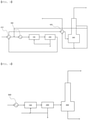
FIGS. 1 to 3 are process flow diagrams for a method of decomposing phenol-based by-product according to an exemplary embodiment of the present invention, respectively. -
FIG. 4 is a process flow diagram for a method of decomposing phenol-based by-product according to the comparative example. - The terms and words used in the description and claims of the present invention are not to be construed limitedly as having general or dictionary meanings but are to be construed as having meanings and concepts meeting the technical ideas of the present invention, based on a principle that the inventors are able to appropriately define the concepts of terms in order to describe their own inventions in the best mode.
- In the present invention, the term "stream" may refer to a fluid flow in a process, or may refer to a fluid itself flowing in a pipe. Specifically, the "stream" may refer to both a fluid itself flowing in a pipe connecting each device and a fluid flow. In addition, the fluid may refer to a gas or a liquid.
- Hereinafter, the present invention will be described in more detail with reference to the
FIGS. 1 to 3 for better understanding of the present invention. - According to the present invention, a method of decomposing phenol-based by-product is provided. The method of decomposing phenol-based by-product may include: introducing a phenol-based by-product stream, a first stream of a side discharge stream from a
decomposition device 300, and a process water stream to amixing device 100 and mixing the streams; introducing a discharge stream from themixing device 100 to alayer separation device 200 to phase-separate the stream into an oil phase and an aqueous phase; passing an oil stream discharged from thelayer separation device 200 through any one or more of afirst heat exchanger 410 and asecond heat exchanger 420 and introducing the stream to thedecomposition device 300 to carry out decomposition; and supplying the first stream of the side discharge stream from thedecomposition device 300 to themixing device 100, forming a mixed stream of a second stream of the side discharge stream with a lower discharge stream and discharging the mixed stream, and recovering effective components from an upper discharge stream. - According to an exemplary embodiment of the present invention, the phenol-based by-product may include any one or more of phenol-based by-product produced in a phenol preparation process and phenol-based by-product produced in a bisphenol A preparation process. For example, the phenol-based by-product may be phenol-based by-product produced in the phenol preparation process, phenol-based by-product produced in the bisphenol A preparation process, or a mixture of the phenol-based by-product produced in the phenol preparation process and the phenol-based by-product produced in the bisphenol A preparation process.
- The phenol preparation process may be carried out by the Hock process described above. Specifically, the phenol preparation process may be carried out by a step of decomposing and purifying cumene hydroperoxide prepared by an oxidation reaction of cumene and separating phenol and acetone. The step of decomposing and purifying cumene hydroperoxide prepared by the oxidation reaction of cumene to separate phenol and acetone is a step of using a cumene purification process and a phenol/acetone purification process. First, propylene and benzene are alkylated to prepare cumene and then heavy/light by-products are discharged by a purification process and cumene is purified and separated. Subsequently, the purified cumene is oxidized to prepare cumene hydroperoxide (CHP), the cumene hydroperoxide (CHP) is decomposed under a common acid catalyst such as sulfuric acid (H2SO4) to produce phenol, acetone, α-methylstyrene (AMS), and heavy by-products, and through a purification process, α-methylstyrene (AMS) and heavy by-products are discharged and phenol and acetone are purified and separated.
- Since a product stream produced by the reaction process described above is present in a state in which phenol, acetone, and various by-products are mixed, a series of separation processes for separating phenol from the product stream is required.
- The product stream is introduced to a separate separation device, in which an acetone-based mixture including unreacted cumene, acetone, α-methylstyrene, hydroxyacetone, and the like is separated in the tower top of the separation device and a phenol-based mixture including phenol, a part of α-methylstyrene and 2-methylbenzofuran, other by-products, and the like is separated in the tower bottom of the separation device.
- The phenol-based mixture separated from the tower bottom of the separation device is introduced to a phenol column, in which phenol is separated in the tower top of the phenol column and phenol-based by-product such as dicumyl peroxide, cumylphenol, alpha-methylstyrene dimer, and tar are separated in the tower bottom of the phenol column. As a result, the phenol-based by-product produced from the phenol preparation process may include some effective components such as phenol, cumene, and α-methylstyrene, and tar.
- In addition, the bisphenol A preparation process may be carried out by a method of reacting phenol and acetone prepared by the Hock process described above to prepare bisphenol A, and recovering bisphenol A from the reaction product. Specifically, the bisphenol A preparation process may be carried out by: decomposing and purifying cumene hydroperoxide prepared by an oxidation reaction of cumene to separate phenol and acetone; separating bisphenol A prepared by reacting the separated phenol and acetone and decomposing a stream including unseparated bisphenol A under an aqueous alkaline solution; and separating the reaction product by the decomposition reaction, phenol-based by-product, and acetone-based by-products.
- The step of decomposing and purifying cumene hydroperoxide prepared by the oxidation reaction of cumene to separate phenol and acetone is a step of using a cumene purification process and a phenol/acetone purification process. First, propylene and benzene are alkylated to prepare cumene and then heavy/light by-products are discharged by a purification process and cumene is purified and separated. Subsequently, the purified cumene is oxidized to prepare cumene hydroperoxide (CHP), the cumene hydroperoxide (CHP) is decomposed under a common acid catalyst such as sulfuric acid (H2SO4) to produce phenol, acetone, α-methylstyrene (AMS), and heavy by-products, and through a purification process, α-methylstyrene (AMS) and heavy by-products are discharged and phenol and acetone are purified and separated.
- The step of separating bisphenol A prepared by reacting the separated phenol and acetone and decomposing a stream including unseparated bisphenol A under an aqueous alkaline solution is a step of using a bisphenol A (BPA) purification process. First, the purified and separated phenol and acetone are reacted to prepare bisphenol A, more correctly crude bisphenol A, and then a crystallization process was carried out to prepare bisphenol A having an improved purity. Bisphenol A prepared as such is separated by a BPA purification process and by-products including unseparated bisphenol A are decomposed under an excessive amount of the aqueous alkaline solution having properties of a base such as NaOH, KOH, and LiOH.
- In the step of separating the reaction product by the decomposition reaction, phenol-based by-product, and acetone-based by-products, the stream after the decomposition reaction may be supplied to a separation device to separate an acetone-based mixture in a tower top of the separation device and separate a reaction product in a tower bottom of the separation device. The reaction product is introduced to a bisphenol A/phenol column where bisphenol A is separated in the tower top, and phenol-based by-product such as bisphenol A, phenol, dicumyl peroxide, cumylphenol, an α-methylstyrene dimer, and tar are separated in the tower bottom. Here, the phenol-based by-product include bisphenol A which is a product, and effective components such as cumene and α-methylstyrene, in addition to tar which is an impurity.
- As a result, the phenol-based by-product produced from the bisphenol A preparation process may include some effective components such as phenol, cumene, and α-methylstyrene, and tar, with bisphenol A.
- Therefore, a mixture of the phenol-based by-product produced in the bisphenol A preparation process and phenol-based by-product produced in the phenol preparation process may include one or more selected from the group consisting of bisphenol A, phenol, α-methylstyrene, acetophenone, cumylphenol, and an α-methylstyrene dimer. As a specific example, the phenol-based by-product may include two or more selected from the group consisting of bisphenol A, phenol, α-methylstyrene, acetophenone, cumylphenol, and an α-methylstyrene dimer, or all of them.
- The phenol-based by-product may include the phenol-based by-product produced in the bisphenol A preparation process and the phenol-based by-product produced in the phenol preparation process at a flow rate ratio of 1:2 to 10. For example, the phenol-based by-product may include the phenol-based by-product produced in the bisphenol A preparation process and the phenol-based by-product produced in the phenol preparation process at a flow rate ratio of 1:2 to 10, 1:4 to 10, or 1:6 to 10. As such, it may be preferred to decompose phenol-based by-product having a high content of the phenol-based by-product produced in the phenol preparation process relative to the phenol-based by-product produced in the bisphenol A preparation process, in terms of preventing a load on the
decomposition device 300 and reducing an amount of energy used in the process. - According to an exemplary embodiment of the present invention, the phenol preparation process and the bisphenol A preparation process may be carried out by including the acid decomposition reaction of cumene hydroperoxide described above. Here, since the acid decomposition reaction of cumene hydroperoxide is carried out by including an acid, an acid decomposition reaction solution includes an acid. Therefore, in order to obtain phenol and acetone by a process such as distillation from the acid decomposition reaction solution, a process of neutralizing the acid decomposition reaction solution is needed.
- Thus, the acid decomposition reaction solution is neutralized by an aqueous basic solution before being separated, where in the neutralized acid decomposition reaction solution, salts from a reaction between an acid used in the acid decomposition reaction and a base such as an aqueous basic solution are produced. The acid decomposition reaction solution neutralized by a neutralization process is separated into an oil phase and an aqueous phase and a separation process for obtaining phenol and acetone from the separated oil phase is carried out, and most of the salts are removed with the aqueous phase, but some salts remain in the oil phase.
- The salts remain in the phenol-based by-product described in the present invention. The salts remaining in the phenol-based by-product as such causes corrosion, occlusion, and deposition of the
decomposition device 300 during the decomposition of the phenol-based by-product for obtaining effective components from the phenol-based by-product, thereby resulting in device failure. Therefore, during the decomposition of the phenol-based by-product, it is important to minimize salts in the phenol-based by-product. - Thus, as a method for removing salts in the phenol-based by-product, a process water is introduced before decomposing the phenol-based by-product, to remove the salts, may be considered, but in this case, phase separation of the oil phase and the aqueous phase is not carried out well, and thus, the salts may not be sufficiently removed.
- In addition, a method of introducing an organic material such as cumene and α-methylstyrene discharged as an effective component from an acetone column and the like in the phenol preparation process together with the process water to the phenol-based by-product, thereby removing salts, may be considered, but in this case, since cumene and α-methylstyrene should be obtained as a product again, an overload occurs in the phenol preparation process and the entire operation energy is increased.
- In addition, a method of introducing an organic material such as an upper discharge stream of the
decomposition device 300 including effective components for decomposing the phenol-based by-product to the phenol-based by-product with the process water, thereby removing salts, may be considered, but since the method uses the upper discharge stream of thedecomposition device 300 obtained as effective components as it is, purification efficiency is decreased and the stream to be refluxed is decreased, so that cooling/heating for operating a condenser is further needed in the upper portion of thedecomposition device 300, resulting in an increase in overall operation energy. However, according to the method of decomposing phenol-based by-product according to the present invention, it is possible to minimize salts in the phenol-based by-product, and thus, it is possible to stably operate the phenol-based by-product decomposition device 300, and the phenol-based by-product may be decomposed to effectively obtain effective components. - Specifically, in the present invention, as a method of removing salts in the phenol-based by-product, before decomposing the phenol-based by-product, the phenol-based by-product stream is supplied to a
mixing device 100, and the side discharge stream from thedecomposition device 300 and a process water stream are introduced separately to themixing device 100, thereby minimizing salts remaining the phenol-based by-product. Here, as the side discharge stream from thedecomposition device 300 supplied to themixing device 100, a first stream which is a part of the side discharge stream of thedecomposition device 300 may be supplied. - The phenol-based by-product may include one or more selected from the group consisting of bisphenol A, phenol, α-methylstyrene, acetophenone, cumylphenol, and an α-methylstyrene dimer, as described above. As a specific example, the phenol-based by-product may include two or more selected from the group consisting of bisphenol A, phenol, α-methylstyrene, acetophenone, cumylphenol, and an α-methylstyrene dimer, or all of them.
- The process water is for dissolving salts in the phenol-based by-product stream therein and removing the salts, and may mean including all various aqueous solutions such as an acidic aqueous solution and a basic aqueous solution, in addition to distilled water.
- The process water may have a pH of 3.5 to 7, 3.5 to 5.5, or 3.5 to 4.5, and within the range, corrosion of the
mixing device 100 and thelayer separation device 200 is prevented, solubility of the salts is improved, and phase separation ability in separation of an oil phase and an aqueous phase in thelayer separation device 200 may be improved. - The
mixing device 100 may be a mixer for mixing the phenol-based by-product and the process water. As a specific example, the mixer may be provided with a line mixer or a static mixer for easily carrying out mixing of the phenol-based by-product and the process water. - The side discharge stream from the
decomposition device 300 is a stream discharged from the side of thedecomposition device 300 described later, and may include one or more selected from the group consisting of phenol, acetophenone, isopropylphenol, α-methylstyrene, and cumene. As a specific example, the side discharge stream from thedecomposition device 300 may include phenol, acetophenone, isopropylphenol, α-methylstyrene, and cumene. The reason why the side discharge stream from thedecomposition device 300 is introduced to themixing device 100 is that acetophenone included in the side discharge stream from thedecomposition device 300 activates phase separation of an oil phase and an aqueous phase including salts in the phase separation using thelayer separation device 200 described later, thereby minimizing salts remaining in the oil phase. - According to an exemplary embodiment of the present invention, the phenol-based by-product are a stream supplied from any one process of the phenol preparation process and the bisphenol A preparation process, and a supplied temperature may be high, for example, in a range of 200°C or higher, 200°C to 300°C, or 200°C to 250°C. Therefore, in order to prevent vaporization of the process water before supplying the phenol-based by-product stream to the
mixing device 100, the phenol-based by-product stream may be cooled. Specifically, the phenol-based by-product stream may be cooled using aseparate cooler 500 and then supplied to thelayer separation device 200. In addition, the phenol-based by-product stream may be cooled by being passed through afirst heat exchanger 410, before being cooled in the cooler 500. Specifically, the phenol-based by-product stream may be cooled by heat exchange with the oil stream discharged from thelayer separation device 200 described later in thefirst heat exchanger 410, and then, may be further cooled in the cooler 500. As such, energy for cooling the phenol-based by-product stream may be reduced by the heat exchange with the stream in the process, and simultaneously, the oil stream discharged from thelayer separation device 200 may be heated before being supplied to thedecomposition device 300, thereby reducing energy used in thedecomposition device 300. - The phenol-based by-product stream may be introduced to the
mixing device 100 with the first stream of the side discharge stream from thedecomposition device 300 and the process water stream and be mixed therewith. For example, the phenol-based by-product stream and the first stream of the side discharge stream from thedecomposition device 300 may be mixed before being cooled in the cooler 500 and be cooled by the cooler 500, and after being cooled, may be introduced to themixing device 100 and be mixed with the process water introduced to themixing device 100. - The phenol-based by-product stream, the first stream of the side discharge stream from the
decomposition device 300, and the process water stream, which are introduced to themixing device 100, may be 1:0.2 to 0.8:1 to 3, 1:0.3 to 0.7:1.2 to 2.8, or 1:0.4 to 0.6:1.3 to 1.8. By controlling the flow rate ratio of the phenol-based by-product stream, the first stream of the side discharge stream from thedecomposition device 300, and the process water stream to the above range, not only the mixing of the phenol-based by-product stream, the first stream of the side discharge stream from thedecomposition device 300, and the process water stream but also the phase separation ability of the oil phase and the aqueous phase in thelayer separation device 200 described later is improved, and removal efficiency of salts included in the phenol-based by-product is improved. - According to an exemplary embodiment of the present invention, a discharge stream from the
mixing device 100 which is discharged from themixing device 100 is supplied to thelayer separation device 200, and may be phase-separated into the oil phase and the aqueous phase in thelayer separation device 200. Specifically, in thelayer separation device 200, the discharge stream from themixing device 100 may be phase-separated into the oil phase and the aqueous phase, for removing salts included in the discharge stream from themixing device 100 and introducing the stream to thedecomposition device 300. - The oil stream discharged from the
layer separation device 200 is a stream obtained by removing salts from the phenol-based by-product stream and may be used as a supply stream to thedecomposition device 300, and the oil stream discharged from thelayer separation device 200 is in a state of having a minimized content of salts, and thus, may prevent corrosion, occlusion, deposition, and the like of thedecomposition device 300 in the decomposition reaction of thedecomposition device 300. - The aqueous stream discharged from the
layer separation device 200 may include salts remaining in the phenol-based by-product and the process water. Accordingly, salts may be removed from the phenol-based by-product stream. - A part of the stream of the aqueous stream discharged from the
layer separation device 200 may be supplied to themixing device 100 and be reused. In addition, of the aqueous stream discharged from thelayer separation device 200, the remaining stream which has not been supplied to themixing device 100 may be discharged as waste water including salts. - The
layer separation device 200 may be a drum for phase-separating the oil phase and the aqueous phase. - For phase-separating the oil phase and the aqueous phase from the
layer separation device 200, a step of retaining the discharge stream from themixing device 100 in thelayer separation device 200 for 1 hour to 10 hours, 2 hours to 8 hours, or 3 hours to 5 hours, may be included. As such, when the stream discharged from themixing device 100 is retained in thelayer separation device 200, phase separation may occur more clearly, and thus, salts may be removed as much as possible from the phenol-based by-product. - The oil stream discharged from the
layer separation device 200 may be supplied to thedecomposition device 300 for a decomposition reaction. Here, the oil stream discharged from thelayer separation device 200 may be heated using the stream in the process before being supplied to thedecomposition device 300, while being passed through any one or more of thefirst heat exchanger 410 and thesecond heat exchanger 420. For example, the oil stream discharged from thelayer separation device 200 may be heated using the phenol-based by-product stream while being passed through thefirst heat exchanger 410, heated using a mixed stream of the second stream of the side discharge stream from thedecomposition device 300 described later and the lower discharge stream while being passed through thesecond heat exchanger 420, or heated secondly while being passed through both thefirst heat exchanger 410 and thesecond heat exchanger 420. As a result, the oil stream discharged from thelayer separation device 200 may be supplied to thedecomposition device 300 after being heated using the stream in the process while being passed through any one or more of thefirst heat exchanger 410 and thesecond heat exchanger 420. - According to an exemplary embodiment of the present invention, decomposition carried out in the
decomposition device 300 may be thermal decomposition, and thedecomposition device 300 for carrying out this may be a thermal cracker. As a specific example, the thermal cracker may be a reactor-distillation tower integrated separation device. - The effective components are separated from the upper portion of the
decomposition device 300, and for effectively separating a heavy material including tar from the lower portion, thedecomposition device 300 may be operated at a temperature of 260°C to 370°C, 290°C to 370°C, or 300°C to 350°C and a pressure of 0.1 bar to 3 bar, 0.1 bar to 2 bar, or 0.1 bar to 1.0 bar. - In the
decomposition device 300, the effective components may be separated from the upper discharge stream. The effective components may include one or more selected from the group consisting of, for example, phenol, α-methylstyrene, and cumene. In addition, the lower discharge stream from thedecomposition device 300 is a stream including tar, and may be recovered and reused as a fuel and the like. - The side discharge stream from the
decomposition device 300 may be discharged at 25% to 90%, 40% to 90%, or 50% to 90% of the total number of stages of thedecomposition device 300. In this case, acetophenone discharged to the upper discharge stream from thedecomposition device 300 may be significantly reduced. - The side discharge stream from the
decomposition device 300 may include 40 wt% or more of acetophenone. For example, the side discharge stream from thedecomposition device 300 may include 40 wt% to 99 wt%, 55 wt% to 99 wt%, or 60 wt% to 99 wt% of acetophenone. The acetophenone is an organic material included in the phenol-based by-product stream, and since it acts as an impurity in contrast to the effective components obtained by the phenol-based by-product decomposition reaction, it is preferred to minimize the content of acetophenone in the effective components. Therefore, when according to the present invention, the side discharge stream from thedecomposition device 300 includes 40 wt% or more of acetophenone, the side discharge stream from thedecomposition device 300 may be separated to minimize the content of acetophenone in the effective components obtained by the phenol-based by-product decomposition reaction, and thus, it is advantageous for obtaining the effective components. - The side discharge stream from the
decomposition device 300 may branch to a first stream and a second stream. For example, the first stream of the side discharge stream from thedecomposition device 300 is supplied to themixing device 100 to improve salt removal efficiency in the phenol-based by-product stream and the second stream is passed through thesecond heat exchanger 420 and discharged, whereby pollutants accumulated in thesecond heat exchanger 420 may be dissolved and removed while the oil stream discharged from thelayer separation device 200 is heated and the flowability of the lower discharge stream from thedecomposition device 300 is improved. - Specifically, as described above, the first stream of the side discharge stream from the
decomposition device 300 having a high content of acetophenone may be used to effectively remove salts included in the phenol-based by-product stream. - In addition, the second stream of the side discharge stream from the
decomposition device 300 may be used to improve the flowability of the lower discharge stream from thedecomposition device 300 having a high content of tar to have bad flowability. For example, the lower discharge stream from thedecomposition device 300 is mixed with the second stream to form a mixed stream, and the mixed stream may be passed through thesecond heat exchanger 420 to be discharged. Thus, since the viscosity of the lower discharge stream from thedecomposition device 300 may be lowered to improve flowability, and simultaneously, the organic material included in the side discharge stream from thedecomposition device 300 has pollutants accumulated in the heat exchanger, for example, has a composition, a temperature, and the like appropriate for dissolving a tar component, the pollutants accumulated in the inner wall, the pipe, and the like of the heat exchanger may be effectively dissolved within a short time to be removed. - In addition, since the
decomposition device 300 is operated at a high temperature, the side discharge stream is also discharged at a high temperature, and the second stream of the side discharge stream from thedecomposition device 300 at a high temperature is used as a heat source for heating the stream in the process, thereby reducing energy. For example, the temperature of the side discharge stream from thedecomposition device 300 may be 150°C to 400°C, 150°C to 300°C, or 180°C to 250°C. As such, the second stream of the side discharge stream from thedecomposition device 300 at a high temperature is passed through thesecond heat exchanger 420 with the lower discharge stream from thedecomposition device 300 and discharged, thereby improving the flowability of the lower discharge stream from thedecomposition device 300 and also heating the oil stream of thelayer separation device 200 which has been passed through thefirst heat exchanger 410 supplied to thesecond heat exchanger 420. - According to an exemplary embodiment of the present invention, in the method of decomposing phenol-based by-product, if necessary, devices such as a distillation column (not shown), a condenser (not shown), a reboiler (not shown), a valve (not shown), a pump (not shown), a separator (not shown), and a mixer (not shown) may be further installed.
- Hereinabove, the method of decomposing phenol-based by-product according to the present invention has been described and illustrated in the drawings, but the description and the illustration in the drawings are the description and the illustration of only core constitutions for understanding of the present invention, and in addition to the process and apparatus described above and illustrated in the drawings, the process and the apparatus which are not described and illustrated separately may be appropriately applied and used for carrying out the method of decomposing phenol-based by-product according to the present invention.
- Hereinafter, the present invention will be described in more detail by the Examples. However, the following Examples are provided for illustrating the present invention. It is apparent to a person skilled in the art that various modifications and alterations may be made without departing from the scope and spirit of the present invention, and the scope of the present invention is not limited thereto.
- Referring to the process flow diagram illustrated in
FIG. 1 , the process was simulated, using an Aspen Plus simulator from Aspen Technology, Inc. Specifically, a phenol-based by-product stream having the composition shown in the following Table 1 having a flow rate of 1,000 kg/hr was passed through afirst heat exchanger 410 at a temperature of 211°C, mixed with a first stream of a side discharge stream from adecomposition device 300, supplied to amixing device 100 in a state of being cooled to 80°C by passing the stream through a cooler 500, and mixed with a process water stream at pH 4 in themixing device 100. A flow ratio of the phenol-based by-product stream: the first stream of the side discharge stream from the decomposition device 300: the process water stream was controlled to 1:0.25:1.25, based on 1,000 kg/hr of the phenol-based by-product stream. - A discharge stream from the
mixing device 100 was supplied to alayer separation device 200 and retained for 5 hours in thelayer separation device 200, and an oil stream discharged therefrom was supplied to thedecomposition device 300 operated at 0.1 KG in a state of being heated to 136°C by passing the stream through thefirst heat exchanger 410. - Effective components were obtained from the upper discharge stream from the
decomposition device 300, the first stream of the side discharge stream discharged at 200°C was supplied to themixing device 100, and the second stream was mixed with the lower discharge stream and discharged. - The compositions of the upper discharge stream and the side discharge stream from the
decomposition device 300 are shown in the following Table 2.[Table 1] Classification Phenol-based by-product stream Phenol (wt%) 4.85 α-methylstyrene (wt%) 7.14 Acetophenone (wt%) 11.60 Cumylphenol (wt%) 15.32 α-methylstyrene dimer (wt%) 10.74 Bisphenol A (wt%) 11.56 Others (wt%) 38.79 Total (wt%) 100.00 [Table 2] Classification Upper discharge stream from decomposition device Side discharge stream from decomposition device Phenol (wt%) 32.99 19.87 α-methylstyrene (wt%) 50.07 5.92 Cumene (wt%) 11.83 0.94 Acetophenone (wt%) 0.01 46.75 Isopropylphenol (wt%) 0.00 26.19 Others (wt%) 5.10 0.33 Total (wt%) 100.00 100.00 - Referring to the process flow diagram illustrated in
FIG. 2 , the process was simulated, using an Aspen Plus simulator from Aspen Technology, Inc. Specifically, a phenol-based by-product stream having the composition shown in Table 1 having a flow rate of 1,000 kg/hr was mixed with a first stream of a side discharge stream from adecomposition device 300 at a temperature of 211°C, supplied to amixing device 100 in a state of being cooled to 80°C by passing the stream through a cooler 500, and mixed with a process water stream at pH 4 in themixing device 100. A flow ratio of the phenol-based by-product stream: the first stream of the side discharge stream from the decomposition device 300: the process water stream was controlled to 1:0.25:1.25, based on 1,000 kg/hr of the phenol-based by-product stream. - The discharge stream from the
mixing device 100 was supplied to alayer separation device 200 and retained for 5 hours in thelayer separation device 200, and an oil stream discharged therefrom was supplied to thedecomposition device 300 operated at 0.1 KG in a state of being heated to 159 °C by passing the stream through thesecond heat exchanger 420. - Effective components were obtained from the upper discharge stream from the
decomposition device 300, the first stream of the side discharge stream discharged at 200°C was supplied to themixing device 100, and the second stream was mixed with the lower discharge stream and passed through thesecond heat exchanger 420 to be discharged. - Referring to the process flow diagram illustrated in
FIG. 3 , the process was simulated, using an Aspen Plus simulator from Aspen Technology, Inc. Specifically, a phenol-based by-product stream having the composition shown in Table 1 having a flow rate of 1,000 kg/hr was passed through afirst heat exchanger 410 at a temperature of 211°C, mixed with a first stream of a side discharge stream from adecomposition device 300, supplied to amixing device 100 in a state of being cooled to 80°C by passing the stream through a cooler 500, and mixed with a process water stream at pH 4 in themixing device 100. A flow ratio of the phenol-based by-product stream: the first stream of the side discharge stream from the decomposition device 300: the process water stream was controlled to 1:0.25:1.25, based on 1,000 kg/hr of the phenol-based by-product stream. - The discharge stream from the
mixing device 100 was supplied to alayer separation device 200 and retained for 5 hours in thelayer separation device 200, and an oil stream discharged therefrom was supplied to thedecomposition device 300 operated at 0.1 KG in a state of being heated to 190 °C by passing the stream through thefirst heat exchanger 410 and thesecond heat exchanger 420. - Effective components were obtained from the upper discharge stream from the
decomposition device 300, the first stream of the side discharge stream discharged at 200°C was supplied to themixing device 100, and the second stream was mixed with the lower discharge stream and passed through thesecond heat exchanger 420 to be discharged. - Referring to the process flow diagram illustrated in
FIG. 4 , the process was simulated, using an Aspen Plus simulator from Aspen Technology, Inc. Specifically, a phenol-based by-product stream having the composition shown in Table 1 at a temperature of 211°C was cooled to 80°C using a cooler 500 at a flow rate of 1,000 kg/hr, and then supplied to amixing device 100 with a process water stream at pH 4. A flow ratio of the phenol-based by-product stream: the process water stream introduced to themixing device 100 was controlled to 1:1.25, based on 1,000 kg/hr of the phenol-based by-product stream. - The discharge stream from the
mixing device 100 was supplied to alayer separation device 200 and retained for 5 hours in thelayer separation device 200, and an oil stream discharged therefrom was supplied to thedecomposition device 300 operated at 0.1 KG. - The effective components were obtained from the upper discharge stream from the
decomposition device 300, and the lower discharge stream was discharged. - Temperature (°C) and amounts of energy used (Gcal/hr) of the oil streams discharged from the
layer separation device 200 supplied to thedecomposition layer 300 in each process of Examples 1 to 3 and Comparative Example 1 are shown in the following Table 3.[Table 3] Example 1 Example 2 Example 3 Comparative Example 1 Temperature of oil stream (°C) 136 159 190 80 Amount of energy used (Gcal/hr) Cooler 0.22 0.38 0.22 0.38 Decomposition device 0.72 0.64 0.54 0.86 Total 0.94 1. 02 0.76 1.24 - Referring to Table 3, in Examples 1 to 3 in which the oil stream discharged from the
layer separation device 200 was heated using any one or more of the phenol-based by-product and the mixed stream of the second stream of the side discharge stream and the lower discharge stream from thedecomposition device 300, it was confirmed that the amount of energy used in the process was decreased. In particular, in Example 3 in which the oil stream discharged from thelayer separation device 200 was heated using the phenol-based by-product stream in thefirst heat exchanger 410 and the oil stream heated in thefirst heat exchanger 410 was further heated using a mixed stream of the second stream of the side discharge stream and the lower discharge stream in thesecond heat exchanger 420, it was confirmed that the amount of energy used was decreased the most. - In comparison, in Comparative Example 1 in which the oil stream discharged from the
layer separation device 200 was supplied to thedecomposition device 300 without separate heating, it was confirmed that the amount of energy used in the process was significantly increased.
Claims (11)
- A method of decomposing phenol-based by-product, the method comprising:introducing a phenol-based by-product stream, a first stream of a side discharge stream from a decomposition device, and a process water stream to a mixing device and mixing the streams;introducing a discharge stream from the mixing device to a layer separation device to phase-separate the stream into an oil phase and an aqueous phase;passing an oil stream discharged from the layer separation device through any one or more of a first heat exchanger and a second heat exchanger and introducing the stream to the decomposition device to carry out decomposition; andsupplying the first stream of the side discharge stream from the decomposition device to the mixing device, forming a mixed stream of a second stream of the side discharge stream from the decomposition device with a lower discharge stream from the decomposition device and discharging the mixed stream, and recovering effective components from an upper discharge stream from the decomposition device.
- The method of decomposing phenol-based by-product of claim 1, wherein the phenol-based by-product include any one or more of phenol-based by-product produced in a phenol preparation process and phenol-based by-product produced in a bisphenol A preparation process.
- The method of decomposing phenol-based by-product of claim 1, wherein the phenol-based by-product include one or more selected from the group consisting of bisphenol A, phenol, α-methylstyrene, acetophenone, cumylphenol, and an α-methylstyrene dimer.
- The method of decomposing phenol-based by-product of claim 1, wherein the side discharge stream from the decomposition device includes one or more selected from the group consisting of phenol, acetophenone, α-methylstyrene, and cumene.
- The method of decomposing phenol-based by-product of claim 1, wherein the side discharge stream from the decomposition device includes 40 wt% or more of acetophenone.
- The method of decomposing phenol-based by-product of claim 1, wherein an operation pressure of the decomposition device is 0.1 KG to 3 KG.
- The method of decomposing phenol-based by-product of claim 1, wherein a temperature of the side discharge stream from the decomposition device is 150°C to 400°C.
- The method of decomposing phenol-based by-product of claim 1, wherein the phenol-based by-product stream is supplied to the mixing device after heat exchange with the oil stream discharged from the layer separation device in the first heat exchanger.
- The method of decomposing phenol-based by-product of claim 8, wherein the mixed stream is heat-exchanged with the oil stream, which has been passed through the first heat exchanger, in the second heat exchanger and then is discharged.
- The method of decomposing phenol-based by-product of claim 1, wherein the effective components include one or more selected from the group consisting of phenol, α-methylstyrene, and cumene.
- The method of decomposing phenol-based by-product of claim 1, wherein the discharge stream from the mixing device is passed through a cooler before being introduced to the layer separation device.
Applications Claiming Priority (2)
| Application Number | Priority Date | Filing Date | Title |
|---|---|---|---|
| KR1020200085515A KR102861475B1 (en) | 2020-07-10 | 2020-07-10 | Method for decomposing phenol-based by-product |
| PCT/KR2021/006714 WO2022010102A1 (en) | 2020-07-10 | 2021-05-31 | Method for decomposing phenol-based by-product |
Publications (3)
| Publication Number | Publication Date |
|---|---|
| EP3971159A1 true EP3971159A1 (en) | 2022-03-23 |
| EP3971159A4 EP3971159A4 (en) | 2022-11-02 |
| EP3971159B1 EP3971159B1 (en) | 2024-10-09 |
Family
ID=79553285
Family Applications (1)
| Application Number | Title | Priority Date | Filing Date |
|---|---|---|---|
| EP21819014.8A Active EP3971159B1 (en) | 2020-07-10 | 2021-05-31 | Method for decomposing phenol-based by-product |
Country Status (5)
| Country | Link |
|---|---|
| US (1) | US12084408B2 (en) |
| EP (1) | EP3971159B1 (en) |
| KR (1) | KR102861475B1 (en) |
| CN (1) | CN114190089B (en) |
| WO (1) | WO2022010102A1 (en) |
Family Cites Families (10)
| Publication number | Priority date | Publication date | Assignee | Title |
|---|---|---|---|---|
| GB1574420A (en) | 1976-12-18 | 1980-09-03 | Bp Chem Int Ltd | Process for recovering crude phenol from catalyst-free cumene hydroperoxide cleavage reaction products |
| EP0008869B1 (en) * | 1978-08-18 | 1983-03-02 | BP Chemicals Limited | Process for the production of a phenol and a carbonyl compound by the catalysed decomposition of an aromatic hydroperoxide |
| US5510543A (en) | 1994-12-09 | 1996-04-23 | General Electric Company | Removal and neutralization of acid catalyst from products of cumene hydroperoxide cleavage |
| US5504251A (en) * | 1995-03-09 | 1996-04-02 | General Electric Company | Co-cracking of BPA and phenol process tars |
| JP4356377B2 (en) | 2003-07-08 | 2009-11-04 | 三菱化学株式会社 | Method for treating phenol by-product oil and bisphenol A residue |
| CN102992961A (en) | 2012-11-28 | 2013-03-27 | 沙丽 | Novel reactive distillation technology for producing phenol and acetone |
| KR102337898B1 (en) | 2017-11-20 | 2021-12-09 | 주식회사 엘지화학 | Method for decomposing by-products of phenol production process |
| EP3680226B1 (en) | 2017-11-20 | 2023-10-25 | LG Chem, Ltd. | Method for decomposing by-product of phenol production process |
| KR102441602B1 (en) * | 2018-12-20 | 2022-09-06 | 주식회사 엘지화학 | Method of decomposition of phenolic by-products |
| KR102441561B1 (en) * | 2018-12-20 | 2022-09-06 | 주식회사 엘지화학 | Method of decomposition of phenolic by-products and apparatus for decomposition thereof |
-
2020
- 2020-07-10 KR KR1020200085515A patent/KR102861475B1/en active Active
-
2021
- 2021-05-31 WO PCT/KR2021/006714 patent/WO2022010102A1/en not_active Ceased
- 2021-05-31 US US17/619,211 patent/US12084408B2/en active Active
- 2021-05-31 CN CN202180004183.2A patent/CN114190089B/en active Active
- 2021-05-31 EP EP21819014.8A patent/EP3971159B1/en active Active
Also Published As
| Publication number | Publication date |
|---|---|
| WO2022010102A1 (en) | 2022-01-13 |
| US12084408B2 (en) | 2024-09-10 |
| US20220281791A1 (en) | 2022-09-08 |
| KR102861475B1 (en) | 2025-09-17 |
| EP3971159A4 (en) | 2022-11-02 |
| CN114190089A (en) | 2022-03-15 |
| EP3971159B1 (en) | 2024-10-09 |
| KR20220007378A (en) | 2022-01-18 |
| CN114190089B (en) | 2024-09-13 |
Similar Documents
| Publication | Publication Date | Title |
|---|---|---|
| EP3680226B1 (en) | Method for decomposing by-product of phenol production process | |
| US11370735B2 (en) | Method for decomposing phenolic by-product | |
| PL189640B1 (en) | Improved method of obtaining carbolic acid and acetone from cumene | |
| EP3971159B1 (en) | Method for decomposing phenol-based by-product | |
| KR20200077248A (en) | Method for decomposing phenol-based by-product and apparatus for decomposing the same | |
| EP3995476B1 (en) | Method for decomposing phenolic by-product | |
| US11993564B2 (en) | Method of decomposing phenolic by-products | |
| KR102846331B1 (en) | Method for decomposing phenol-based by-product | |
| KR102860383B1 (en) | Method for decomposing phenol-based by-product | |
| KR20180061040A (en) | Removing unit of methanol and acetone and manufacturing system of phenol and bisphenol a comprising the same | |
| KR102860381B1 (en) | Method for decomposing phenol-based by-product | |
| US10532968B2 (en) | Method for purifying phenol | |
| CN102471257A (en) | Process for treating aqueous solution containing water-soluble substances, process for producing alkylbenzene hydroperoxides, and process for producing hydroxybenzenes | |
| WO2007094504A1 (en) | Process for production of dialkylhydroperoxybenzenes | |
| JPH013138A (en) | How to recover resorcinol |
Legal Events
| Date | Code | Title | Description |
|---|---|---|---|
| STAA | Information on the status of an ep patent application or granted ep patent |
Free format text: STATUS: UNKNOWN |
|
| STAA | Information on the status of an ep patent application or granted ep patent |
Free format text: STATUS: THE INTERNATIONAL PUBLICATION HAS BEEN MADE |
|
| PUAI | Public reference made under article 153(3) epc to a published international application that has entered the european phase |
Free format text: ORIGINAL CODE: 0009012 |
|
| STAA | Information on the status of an ep patent application or granted ep patent |
Free format text: STATUS: REQUEST FOR EXAMINATION WAS MADE |
|
| 17P | Request for examination filed |
Effective date: 20211213 |
|
| AK | Designated contracting states |
Kind code of ref document: A1 Designated state(s): AL AT BE BG CH CY CZ DE DK EE ES FI FR GB GR HR HU IE IS IT LI LT LU LV MC MK MT NL NO PL PT RO RS SE SI SK SM TR |
|
| A4 | Supplementary search report drawn up and despatched |
Effective date: 20220929 |
|
| RIC1 | Information provided on ipc code assigned before grant |
Ipc: C07C 45/82 20060101ALI20220923BHEP Ipc: C07C 37/56 20060101ALI20220923BHEP Ipc: C07C 37/50 20060101ALI20220923BHEP Ipc: C07C 1/20 20060101ALI20220923BHEP Ipc: C07C 37/52 20060101ALI20220923BHEP Ipc: C07C 37/86 20060101ALI20220923BHEP Ipc: C07C 15/085 20060101ALI20220923BHEP Ipc: C07C 15/46 20060101ALI20220923BHEP Ipc: C07C 7/04 20060101ALI20220923BHEP Ipc: C07C 39/04 20060101ALI20220923BHEP Ipc: C07C 37/74 20060101AFI20220923BHEP |
|
| DAV | Request for validation of the european patent (deleted) | ||
| DAX | Request for extension of the european patent (deleted) | ||
| GRAP | Despatch of communication of intention to grant a patent |
Free format text: ORIGINAL CODE: EPIDOSNIGR1 |
|
| STAA | Information on the status of an ep patent application or granted ep patent |
Free format text: STATUS: GRANT OF PATENT IS INTENDED |
|
| INTG | Intention to grant announced |
Effective date: 20240730 |
|
| GRAS | Grant fee paid |
Free format text: ORIGINAL CODE: EPIDOSNIGR3 |
|
| GRAA | (expected) grant |
Free format text: ORIGINAL CODE: 0009210 |
|
| STAA | Information on the status of an ep patent application or granted ep patent |
Free format text: STATUS: THE PATENT HAS BEEN GRANTED |
|
| AK | Designated contracting states |
Kind code of ref document: B1 Designated state(s): AL AT BE BG CH CY CZ DE DK EE ES FI FR GB GR HR HU IE IS IT LI LT LU LV MC MK MT NL NO PL PT RO RS SE SI SK SM TR |
|
| REG | Reference to a national code |
Ref country code: CH Ref legal event code: EP |
|
| REG | Reference to a national code |
Ref country code: DE Ref legal event code: R096 Ref document number: 602021020104 Country of ref document: DE |
|
| REG | Reference to a national code |
Ref country code: IE Ref legal event code: FG4D |
|
| REG | Reference to a national code |
Ref country code: LT Ref legal event code: MG9D |
|
| REG | Reference to a national code |
Ref country code: NL Ref legal event code: MP Effective date: 20241009 |
|
| REG | Reference to a national code |
Ref country code: AT Ref legal event code: MK05 Ref document number: 1730480 Country of ref document: AT Kind code of ref document: T Effective date: 20241009 |
|
| PG25 | Lapsed in a contracting state [announced via postgrant information from national office to epo] |
Ref country code: NL Free format text: LAPSE BECAUSE OF FAILURE TO SUBMIT A TRANSLATION OF THE DESCRIPTION OR TO PAY THE FEE WITHIN THE PRESCRIBED TIME-LIMIT Effective date: 20241009 |
|
| PG25 | Lapsed in a contracting state [announced via postgrant information from national office to epo] |
Ref country code: NL Free format text: LAPSE BECAUSE OF FAILURE TO SUBMIT A TRANSLATION OF THE DESCRIPTION OR TO PAY THE FEE WITHIN THE PRESCRIBED TIME-LIMIT Effective date: 20241009 |
|
| PG25 | Lapsed in a contracting state [announced via postgrant information from national office to epo] |
Ref country code: IS Free format text: LAPSE BECAUSE OF FAILURE TO SUBMIT A TRANSLATION OF THE DESCRIPTION OR TO PAY THE FEE WITHIN THE PRESCRIBED TIME-LIMIT Effective date: 20250209 Ref country code: PT Free format text: LAPSE BECAUSE OF FAILURE TO SUBMIT A TRANSLATION OF THE DESCRIPTION OR TO PAY THE FEE WITHIN THE PRESCRIBED TIME-LIMIT Effective date: 20250210 Ref country code: HR Free format text: LAPSE BECAUSE OF FAILURE TO SUBMIT A TRANSLATION OF THE DESCRIPTION OR TO PAY THE FEE WITHIN THE PRESCRIBED TIME-LIMIT Effective date: 20241009 |
|
| PG25 | Lapsed in a contracting state [announced via postgrant information from national office to epo] |
Ref country code: FI Free format text: LAPSE BECAUSE OF FAILURE TO SUBMIT A TRANSLATION OF THE DESCRIPTION OR TO PAY THE FEE WITHIN THE PRESCRIBED TIME-LIMIT Effective date: 20241009 |
|
| PG25 | Lapsed in a contracting state [announced via postgrant information from national office to epo] |
Ref country code: BG Free format text: LAPSE BECAUSE OF FAILURE TO SUBMIT A TRANSLATION OF THE DESCRIPTION OR TO PAY THE FEE WITHIN THE PRESCRIBED TIME-LIMIT Effective date: 20241009 |
|
| PG25 | Lapsed in a contracting state [announced via postgrant information from national office to epo] |
Ref country code: ES Free format text: LAPSE BECAUSE OF FAILURE TO SUBMIT A TRANSLATION OF THE DESCRIPTION OR TO PAY THE FEE WITHIN THE PRESCRIBED TIME-LIMIT Effective date: 20241009 |
|
| PG25 | Lapsed in a contracting state [announced via postgrant information from national office to epo] |
Ref country code: NO Free format text: LAPSE BECAUSE OF FAILURE TO SUBMIT A TRANSLATION OF THE DESCRIPTION OR TO PAY THE FEE WITHIN THE PRESCRIBED TIME-LIMIT Effective date: 20250109 |
|
| PG25 | Lapsed in a contracting state [announced via postgrant information from national office to epo] |
Ref country code: LV Free format text: LAPSE BECAUSE OF FAILURE TO SUBMIT A TRANSLATION OF THE DESCRIPTION OR TO PAY THE FEE WITHIN THE PRESCRIBED TIME-LIMIT Effective date: 20241009 Ref country code: GR Free format text: LAPSE BECAUSE OF FAILURE TO SUBMIT A TRANSLATION OF THE DESCRIPTION OR TO PAY THE FEE WITHIN THE PRESCRIBED TIME-LIMIT Effective date: 20250110 Ref country code: AT Free format text: LAPSE BECAUSE OF FAILURE TO SUBMIT A TRANSLATION OF THE DESCRIPTION OR TO PAY THE FEE WITHIN THE PRESCRIBED TIME-LIMIT Effective date: 20241009 |
|
| PG25 | Lapsed in a contracting state [announced via postgrant information from national office to epo] |
Ref country code: PL Free format text: LAPSE BECAUSE OF FAILURE TO SUBMIT A TRANSLATION OF THE DESCRIPTION OR TO PAY THE FEE WITHIN THE PRESCRIBED TIME-LIMIT Effective date: 20241009 |
|
| PG25 | Lapsed in a contracting state [announced via postgrant information from national office to epo] |
Ref country code: RS Free format text: LAPSE BECAUSE OF FAILURE TO SUBMIT A TRANSLATION OF THE DESCRIPTION OR TO PAY THE FEE WITHIN THE PRESCRIBED TIME-LIMIT Effective date: 20250109 |
|
| PG25 | Lapsed in a contracting state [announced via postgrant information from national office to epo] |
Ref country code: SM Free format text: LAPSE BECAUSE OF FAILURE TO SUBMIT A TRANSLATION OF THE DESCRIPTION OR TO PAY THE FEE WITHIN THE PRESCRIBED TIME-LIMIT Effective date: 20241009 |
|
| PGFP | Annual fee paid to national office [announced via postgrant information from national office to epo] |
Ref country code: DE Payment date: 20250422 Year of fee payment: 5 |
|
| PG25 | Lapsed in a contracting state [announced via postgrant information from national office to epo] |
Ref country code: DK Free format text: LAPSE BECAUSE OF FAILURE TO SUBMIT A TRANSLATION OF THE DESCRIPTION OR TO PAY THE FEE WITHIN THE PRESCRIBED TIME-LIMIT Effective date: 20241009 |
|
| REG | Reference to a national code |
Ref country code: DE Ref legal event code: R097 Ref document number: 602021020104 Country of ref document: DE |
|
| PG25 | Lapsed in a contracting state [announced via postgrant information from national office to epo] |
Ref country code: EE Free format text: LAPSE BECAUSE OF FAILURE TO SUBMIT A TRANSLATION OF THE DESCRIPTION OR TO PAY THE FEE WITHIN THE PRESCRIBED TIME-LIMIT Effective date: 20241009 |
|
| PGFP | Annual fee paid to national office [announced via postgrant information from national office to epo] |
Ref country code: FR Payment date: 20250422 Year of fee payment: 5 |
|
| PG25 | Lapsed in a contracting state [announced via postgrant information from national office to epo] |
Ref country code: RO Free format text: LAPSE BECAUSE OF FAILURE TO SUBMIT A TRANSLATION OF THE DESCRIPTION OR TO PAY THE FEE WITHIN THE PRESCRIBED TIME-LIMIT Effective date: 20241009 |
|
| PG25 | Lapsed in a contracting state [announced via postgrant information from national office to epo] |
Ref country code: SK Free format text: LAPSE BECAUSE OF FAILURE TO SUBMIT A TRANSLATION OF THE DESCRIPTION OR TO PAY THE FEE WITHIN THE PRESCRIBED TIME-LIMIT Effective date: 20241009 |
|
| PG25 | Lapsed in a contracting state [announced via postgrant information from national office to epo] |
Ref country code: CZ Free format text: LAPSE BECAUSE OF FAILURE TO SUBMIT A TRANSLATION OF THE DESCRIPTION OR TO PAY THE FEE WITHIN THE PRESCRIBED TIME-LIMIT Effective date: 20241009 |
|
| PG25 | Lapsed in a contracting state [announced via postgrant information from national office to epo] |
Ref country code: IT Free format text: LAPSE BECAUSE OF FAILURE TO SUBMIT A TRANSLATION OF THE DESCRIPTION OR TO PAY THE FEE WITHIN THE PRESCRIBED TIME-LIMIT Effective date: 20241009 |
|
| PLBE | No opposition filed within time limit |
Free format text: ORIGINAL CODE: 0009261 |
|
| STAA | Information on the status of an ep patent application or granted ep patent |
Free format text: STATUS: NO OPPOSITION FILED WITHIN TIME LIMIT |
|
| PG25 | Lapsed in a contracting state [announced via postgrant information from national office to epo] |
Ref country code: SE Free format text: LAPSE BECAUSE OF FAILURE TO SUBMIT A TRANSLATION OF THE DESCRIPTION OR TO PAY THE FEE WITHIN THE PRESCRIBED TIME-LIMIT Effective date: 20241009 |
|
| 26N | No opposition filed |
Effective date: 20250710 |
|
| REG | Reference to a national code |
Ref country code: CH Ref legal event code: H13 Free format text: ST27 STATUS EVENT CODE: U-0-0-H10-H13 (AS PROVIDED BY THE NATIONAL OFFICE) Effective date: 20251223 |
|
| PG25 | Lapsed in a contracting state [announced via postgrant information from national office to epo] |
Ref country code: LU Free format text: LAPSE BECAUSE OF NON-PAYMENT OF DUE FEES Effective date: 20250531 |
|
| PG25 | Lapsed in a contracting state [announced via postgrant information from national office to epo] |
Ref country code: CH Free format text: LAPSE BECAUSE OF NON-PAYMENT OF DUE FEES Effective date: 20250531 |
|
| REG | Reference to a national code |
Ref country code: BE Ref legal event code: MM Effective date: 20250531 |
|
| PG25 | Lapsed in a contracting state [announced via postgrant information from national office to epo] |
Ref country code: MC Free format text: LAPSE BECAUSE OF FAILURE TO SUBMIT A TRANSLATION OF THE DESCRIPTION OR TO PAY THE FEE WITHIN THE PRESCRIBED TIME-LIMIT Effective date: 20241009 |
|
| PGFP | Annual fee paid to national office [announced via postgrant information from national office to epo] |
Ref country code: GB Payment date: 20260324 Year of fee payment: 6 |
|
| PG25 | Lapsed in a contracting state [announced via postgrant information from national office to epo] |
Ref country code: IE Free format text: LAPSE BECAUSE OF NON-PAYMENT OF DUE FEES Effective date: 20250531 |
|
| PG25 | Lapsed in a contracting state [announced via postgrant information from national office to epo] |
Ref country code: BE Free format text: LAPSE BECAUSE OF NON-PAYMENT OF DUE FEES Effective date: 20250531 |