EP3971035A1 - Pallet-carrier box with an opening system of the sliding type - Google Patents
Pallet-carrier box with an opening system of the sliding type Download PDFInfo
- Publication number
- EP3971035A1 EP3971035A1 EP21197608.9A EP21197608A EP3971035A1 EP 3971035 A1 EP3971035 A1 EP 3971035A1 EP 21197608 A EP21197608 A EP 21197608A EP 3971035 A1 EP3971035 A1 EP 3971035A1
- Authority
- EP
- European Patent Office
- Prior art keywords
- lid
- compartment
- access section
- pins
- box according
- Prior art date
- Legal status (The legal status is an assumption and is not a legal conclusion. Google has not performed a legal analysis and makes no representation as to the accuracy of the status listed.)
- Granted
Links
Images



Classifications
-
- B—PERFORMING OPERATIONS; TRANSPORTING
- B60—VEHICLES IN GENERAL
- B60R—VEHICLES, VEHICLE FITTINGS, OR VEHICLE PARTS, NOT OTHERWISE PROVIDED FOR
- B60R9/00—Supplementary fittings on vehicle exterior for carrying loads, e.g. luggage, sports gear or the like
- B60R9/02—Supplementary fittings on vehicle exterior for carrying loads, e.g. luggage, sports gear or the like at the sides, e.g. on running-board
-
- B—PERFORMING OPERATIONS; TRANSPORTING
- B60—VEHICLES IN GENERAL
- B60P—VEHICLES ADAPTED FOR LOAD TRANSPORTATION OR TO TRANSPORT, TO CARRY, OR TO COMPRISE SPECIAL LOADS OR OBJECTS
- B60P7/00—Securing or covering of load on vehicles
- B60P7/06—Securing of load
- B60P7/08—Securing to the vehicle floor or sides
- B60P7/10—Securing to the vehicle floor or sides the load being plates, cases, or boxes
Definitions
- This invention is generally in the field of commercial automotive accessories; in particular, the invention relates to a pallet-carrier box with a sliding opening system.
- Pallet-carrier boxes are known to be configured to be mounted to the chassis of a commercial motor vehicle, typically underneath a trailer of a truck (as shown by way of example in Figs. 1 and 2 ).
- pallets are stored inside the pallet-carrier boxes, for example those left over after the vehicle load has been delivered, or intended for picking up goods and loading them onto the vehicle. In this way, pallets may be contained and transported tidily in a designated space.
- the boxes are large in size and weight, and include one or two lids, which occlude the interior compartment of the box from one or both sides accessible by the operator (i.e., the sides that face outward from the vehicle or trailer, when the box is mounted thereon).
- the lids are simply hinged to a lower edge of the box so that they rotate downward under their own weight when the operator releases the lid from the box.
- the opening (i.e., downward) rotation of the lid is uncontrolled, and since the weight of the lid is quite heavy, the opening movement may be unexpectedly rapid and cause structural damage to the components of the box or injury to the operator.
- the restraining means typically, lanyards or chains
- An object of this invention is to overcome the aforementioned problems.
- a pallet-carrier box according to this invention is provided with a tilting lid, the movement of which is controlled by means of actuators (active or passive) and possibly dampers.
- the lid is hinged to pins sliding within guides extended along the direction of the depth of the case, so that the lid is accompanied by the pins and the guides to lie parallel to the top and bottom faces of the case.
- Hinged to the pins are actuators (expediently, linear actuators of a passive type, such as gas springs), configured to slow the sliding of the pins at least partially during the first phase of motion of the lid (that of transitioning from the substantially rotational to the translational phase), and instead push the pins in the second phase (the substantially translational phase).
- actuators expediently, linear actuators of a passive type, such as gas springs
- the actuators in combination with any auxiliary dampers, described more fully below are configured in a first step to brake the fall of the lid under the action of its own weight, and in a second step to help to push it towards the horizontal position, all in an expediently automatic manner.
- a pallet-carrier box (9) suitable for being mounted on the chassis of a commercial motor vehicle, comprises a case 10, which in turn includes a pair of upper and lower walls 10a, lying on respective planes defined by a longitudinal direction y and a transverse direction x perpendicular to each other, said planes being mutually parallel and spaced along a vertical direction z perpendicular to the first two.
- the case 10 further comprises a pair of side walls 10b, lying on respective planes defined by the longitudinal y and vertical z directions, such planes being parallel to each other and spaced along the transverse direction x.
- the upper, lower, and side walls 10a, 10b define a compartment 12 adapted to accommodate at least one pallet.
- the compartment 12 may be configured to accommodate at least one pallet sized according to the standards recognized in ISO 6780:2003 ("Flat pallets for intercontinental materials handling — Principal dimensions and tolerances," revised and confirmed in 2014), for example a European-type pallet (as per EUR/EPAL standard), and/or a US-type pallet (as per GMA standard), etc.
- a pair of guides 14 are also provided, associated with respective side walls 10b and extending along the longitudinal direction y, as well as a pair of pins 16, sliding within respective guides 14.
- the pallet-carrier box 9 comprises at least one lid 18, adapted to occlude an access section of the compartment 12 along a plane defined by the transverse x and vertical z directions.
- the lid 18 is hinged to the pins 16 and is movable between a closed condition, in which the lid 18 occludes the access section of the compartment 12 and the pins are located in the guides 14 at a position proximal to said access section of the compartment 12, and an open condition, in which the lid 18 is arranged parallel to a lower wall 10a of the case 10, and the pins are located in the guides 14 at a position distal to said access section of the compartment 12.
- Said primary actuators 20 are adapted to impart a thrust to the respective pins 16 toward the proximal position with respect to the access section of the compartment 12 when the lid 18 is in the closed condition, and a thrust to respective pins 16 toward the distal position relative to the access section of the compartment 12 when the lid 18 is in the open condition.
- a controlled tilting motion is imparted to the lid 18 in the transition from the closed to the open condition, wherein the lid is induced to arrange itself to be parallel to the upper and lower walls 10a.
- each primary actuator 20 is hinged to the respective side wall 10b at a point along the longitudinal direction y between the proximal position and the distal position of the respective pin 16 with respect to the access section of the compartment 12.
- each primary actuator 20 oscillatable between an initial inclination, corresponding to the inclination that the primary actuator 20 assumes when the lid 18 is in the closed condition, a vertical condition, corresponding to the inclination that the primary actuator 20 assumes when the pin 16 is longitudinally located at the point at which said primary actuator 20 is hinged to the respective side wall 10b, and a final inclination, corresponding to the inclination that the primary actuator 20 assumes when the lid 18 is in the open condition.
- the primary actuator 20 will therefore be configured to exert, in the stroke from its initial inclination to its vertical condition, a thrust on the pin 16 toward the position proximal to the access section of the compartment 12 whereby it slows the sliding of said pin 16 toward the position distal from the access section of the compartment 12, and is further configured to exert, in the stroke from its vertical condition to its final inclination, a thrust on the pin 16 toward the position distal to the access section of the compartment 12, whereby it accelerates the sliding of said pin 16 toward the position distal from the access section of the compartment 12.
- the primary actuators 20 may be of the active type, i.e., they may be linear actuators controlled (e.g., by an electronic control unit) to exert a controlled thrust on the pins 16.
- the primary actuators 20 may be passive-type actuators.
- such primary actuators 20 are conventional gas springs.
- the pallet-carrier box 9 further comprises a pair of auxiliary dampers 22 each having a first end hinged to a respective side wall 10b, and the opposite end hinged to the lid 18.
- Said auxiliary dampers 22 are adapted to exert a damping action on the movement of the lid 18 in the transition thereof from the closed condition to the open condition, in particular in the first phase of rotation of the lid 18 around the pins 16.
- the first ends of the auxiliary dampers 22 are hinged to the side walls 10b at a position vertically intermediate between the top and bottom walls 10a of the case 10, and the other ends of the auxiliary dampers 22 are hinged to the lid 18 in proximity to the transverse edge thereof, opposite the edge proximal to the guides 14.
- the auxiliary dampers 22 also act as a fulcrum for transferring the rotational motion of the lid 18 to the pins 16 whereby they slide in the guides 14, so as to transform the conventional rotational motion of the lid according to the prior art into a substantially swinging motion, in a suitably automatic manner.
- the combined action of the primary actuators 20 and the auxiliary dampers 22 therefore allows the movement of the lid 18 to be controlled at each stage of opening, from a substantially rotational to a substantially translational movement, by accompanying the lid 18 until it moves from the vertical closed position to the horizontal open position.
- one or both of the auxiliary dampers 22 are conventional hydraulic dampers.
- the guides 14 are attached to the respective side walls 10b near the joining edge of said side walls 10b with the lower wall 10a, whereby the lid 18 is configured to move from the closed condition to the open condition under the action of its own weight (or, with minimal intervention by the operator, for example by means of an additional push or by holding the lid). Upon completion, the lid 18 will lay below the lower wall 10a of the case 10.
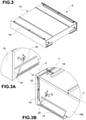
- Fig. 3, 3A and 3B show the lid 18 in the closed condition, wherein said lid 18 is arranged vertically.
- the pins 16 are arranged in the guides 14 in a position proximal to the access section of the compartment 12, the primary actuators 20 are in their initial inclination (whereby they push the pins 16 to said position proximal to the access section of the compartment 12), and the auxiliary dampers 22 are in a vertical position (wherein they are substantially inactive).
- Fig. 4 and 4A show the lid 18 in a transition condition between closed and open.
- the downward rotation of the lid 18 is controlled by the auxiliary dampers 22, which, as they rotate, begin to direct the lid 18 to translate along the guides 14.
- the primary actuators 20 begin their angular stroke from the initial inclination toward the vertical condition.
- Fig. 5 and 5A show the lid 18 in the open condition, wherein said lid 18 is arranged horizontally (and stowed under the lower portion 10a of the case 10).
- the pins 16 are arranged in the guides 14 in a position distal to the access section of the compartment 12, the primary actuators 20 have transitioned to their final inclination, and the auxiliary dampers 22 have returned to a vertical position, but in the opposite direction to that in Fig. 3 (wherein they essentially perform a function of supporting the lid 18 in a horizontal position).
- the guides 14 are attached to respective side walls 10b near the joining edge of said side walls 10b with the upper wall 10a.
- the lid 18 will be arranged above the upper wall 10a of the case 10.
- the operating principle of the opening system is substantially analogous to that described above in reference to the alternative embodiment, except that the weight of the lid 18 does not contribute to promoting the opening movement, which must therefore be imparted manually by the operator and/or in an assisted or automatic manner (by arranging, for example, actuators and/or active dampers).
- the pallet-carrier box 9 may further comprise hooking means 19, which are known per se and adapted to releasably bind the lid 18 to the case 10 when the former is in the closed condition.
- the compartment 12 has a dimension equal to or greater than 800 mm along the longitudinal direction y, a dimension equal to or greater than 800 mm along the transverse direction x, and a dimension equal to or greater than 140 mm along the vertical direction z.
Landscapes
- Engineering & Computer Science (AREA)
- Mechanical Engineering (AREA)
- Transportation (AREA)
- Pallets (AREA)
- Control And Other Processes For Unpacking Of Materials (AREA)
- Wrapping Of Specific Fragile Articles (AREA)
- Closures For Containers (AREA)
Abstract
Description
- This invention is generally in the field of commercial automotive accessories; in particular, the invention relates to a pallet-carrier box with a sliding opening system.
- Pallet-carrier boxes are known to be configured to be mounted to the chassis of a commercial motor vehicle, typically underneath a trailer of a truck (as shown by way of example in
Figs. 1 and2 ). - One or more pallets are stored inside the pallet-carrier boxes, for example those left over after the vehicle load has been delivered, or intended for picking up goods and loading them onto the vehicle. In this way, pallets may be contained and transported tidily in a designated space.
- Because they must accommodate a plurality of relatively bulky items, the boxes are large in size and weight, and include one or two lids, which occlude the interior compartment of the box from one or both sides accessible by the operator (i.e., the sides that face outward from the vehicle or trailer, when the box is mounted thereon).
- The lids are simply hinged to a lower edge of the box so that they rotate downward under their own weight when the operator releases the lid from the box.
- However, this admittedly rudimentary connection system has many drawbacks.
- First of all, the opening (i.e., downward) rotation of the lid is uncontrolled, and since the weight of the lid is quite heavy, the opening movement may be unexpectedly rapid and cause structural damage to the components of the box or injury to the operator. Nor are the restraining means (typically, lanyards or chains) that are used to secure the top edge of the lid to the box sufficient, since they only have the function of stopping the lid from falling so that, as it rotates, it does not continue beyond a certain angle, but without offering any control or aid to the rotation movement.
- In addition, when the operator lifts the lid to return it to the closed position, said lid risks bending and deforming due to its length if the operator does not manipulate it from the center, which may make the operation more inconvenient.
- Such drawbacks, understandably, limit the usability and safety of the product.
- An object of this invention is to overcome the aforementioned problems.
- To achieve this, a pallet-carrier box according to this invention is provided with a tilting lid, the movement of which is controlled by means of actuators (active or passive) and possibly dampers.
- The lid is hinged to pins sliding within guides extended along the direction of the depth of the case, so that the lid is accompanied by the pins and the guides to lie parallel to the top and bottom faces of the case.
- Hinged to the pins are actuators (expediently, linear actuators of a passive type, such as gas springs), configured to slow the sliding of the pins at least partially during the first phase of motion of the lid (that of transitioning from the substantially rotational to the translational phase), and instead push the pins in the second phase (the substantially translational phase).
- In this way, when for example the lid is hinged to the pins along an axis located near a lower edge of the lid (as in the example shown), the actuators (in combination with any auxiliary dampers, described more fully below) are configured in a first step to brake the fall of the lid under the action of its own weight, and in a second step to help to push it towards the horizontal position, all in an expediently automatic manner.
- The aforesaid and other aims and advantages are achieved, according to one aspect of the invention, by a pallet-carrier box having the features defined in claim 1. Preferred embodiments of the invention are defined in the dependent claims.
- The functional and structural features of some preferred embodiments of a pallet-carrier box according to the invention will now be described. Reference is made to the appended drawings, wherein:
-
Fig. 1 and 1A are respectively a schematic perspective and side views of a commercial motor vehicle having a trailer on which a pallet-carrier box is mounted, according to one embodiment of the invention; -
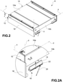
Fig. 2 and 2A are respectively an exploded schematic perspective view of a pallet-carrier box according to an embodiment of the invention, and a detail ofFig. 2 ; -
Fig. 3 through 3B are, respectively, a schematic perspective view of the pallet-carrier box inFig. 2 in a closed configuration, a detail ofFig. 3 from a front view, and the detail ofFig. 3A from a rear view; -
Fig. 4 and 4A are, respectively, a schematic perspective view of the pallet-carrier box inFig. 3 in a semi-open configuration, and a detail ofFig. 4 ; and -
Fig. 5 and 5A are, respectively, a schematic perspective view of the pallet-carrier box inFig. 3 in the open configuration, and a detail ofFig. 5 . - Before describing a plurality of embodiments of the invention in detail, it should be clarified that the invention is not limited in its application to the construction details and configuration of the components presented in the following description or illustrated in the drawings. The invention may assume other embodiments and be implemented or constructed in practice in different ways. It should also be understood that the phraseology and terminology have a descriptive purpose and should not be construed as limiting.
- Referring by way of example to the figures, a pallet-carrier box (9), suitable for being mounted on the chassis of a commercial motor vehicle, comprises a
case 10, which in turn includes a pair of upper andlower walls 10a, lying on respective planes defined by a longitudinal direction y and a transverse direction x perpendicular to each other, said planes being mutually parallel and spaced along a vertical direction z perpendicular to the first two. - The
case 10 further comprises a pair ofside walls 10b, lying on respective planes defined by the longitudinal y and vertical z directions, such planes being parallel to each other and spaced along the transverse direction x. - The upper, lower, and
side walls compartment 12 adapted to accommodate at least one pallet. Preferably, thecompartment 12 may be configured to accommodate at least one pallet sized according to the standards recognized in ISO 6780:2003 ("Flat pallets for intercontinental materials handling — Principal dimensions and tolerances," revised and confirmed in 2014), for example a European-type pallet (as per EUR/EPAL standard), and/or a US-type pallet (as per GMA standard), etc. - A pair of
guides 14 are also provided, associated withrespective side walls 10b and extending along the longitudinal direction y, as well as a pair ofpins 16, sliding withinrespective guides 14. - The pallet-
carrier box 9 comprises at least onelid 18, adapted to occlude an access section of thecompartment 12 along a plane defined by the transverse x and vertical z directions. - The
lid 18 is hinged to thepins 16 and is movable between a closed condition, in which thelid 18 occludes the access section of thecompartment 12 and the pins are located in theguides 14 at a position proximal to said access section of thecompartment 12, and an open condition, in which thelid 18 is arranged parallel to alower wall 10a of thecase 10, and the pins are located in theguides 14 at a position distal to said access section of thecompartment 12. - There is also provided a pair of
primary actuators 20, each having a first end hinged to arespective side wall 10b, and the opposite end hinged to arespective pin 16. Therefore, suchprimary actuators 20 are oscillatable about axes parallel to the transverse direction x. - Said
primary actuators 20 are adapted to impart a thrust to therespective pins 16 toward the proximal position with respect to the access section of thecompartment 12 when thelid 18 is in the closed condition, and a thrust torespective pins 16 toward the distal position relative to the access section of thecompartment 12 when thelid 18 is in the open condition. In this manner, a controlled tilting motion is imparted to thelid 18 in the transition from the closed to the open condition, wherein the lid is induced to arrange itself to be parallel to the upper andlower walls 10a. - Expediently, each
primary actuator 20 is hinged to therespective side wall 10b at a point along the longitudinal direction y between the proximal position and the distal position of therespective pin 16 with respect to the access section of thecompartment 12. - With such a configuration, it is possible to make each
primary actuator 20 oscillatable between an initial inclination, corresponding to the inclination that theprimary actuator 20 assumes when thelid 18 is in the closed condition, a vertical condition, corresponding to the inclination that theprimary actuator 20 assumes when thepin 16 is longitudinally located at the point at which saidprimary actuator 20 is hinged to therespective side wall 10b, and a final inclination, corresponding to the inclination that theprimary actuator 20 assumes when thelid 18 is in the open condition. Expediently, theprimary actuator 20 will therefore be configured to exert, in the stroke from its initial inclination to its vertical condition, a thrust on thepin 16 toward the position proximal to the access section of thecompartment 12 whereby it slows the sliding of saidpin 16 toward the position distal from the access section of thecompartment 12, and is further configured to exert, in the stroke from its vertical condition to its final inclination, a thrust on thepin 16 toward the position distal to the access section of thecompartment 12, whereby it accelerates the sliding of saidpin 16 toward the position distal from the access section of thecompartment 12. - According to an embodiment not shown, the
primary actuators 20 may be of the active type, i.e., they may be linear actuators controlled (e.g., by an electronic control unit) to exert a controlled thrust on thepins 16. - Alternatively, the
primary actuators 20 may be passive-type actuators. Preferably, suchprimary actuators 20 are conventional gas springs. - Preferably, the pallet-
carrier box 9 further comprises a pair ofauxiliary dampers 22 each having a first end hinged to arespective side wall 10b, and the opposite end hinged to thelid 18. - Said
auxiliary dampers 22 are adapted to exert a damping action on the movement of thelid 18 in the transition thereof from the closed condition to the open condition, in particular in the first phase of rotation of thelid 18 around thepins 16. - Expediently, the first ends of the
auxiliary dampers 22 are hinged to theside walls 10b at a position vertically intermediate between the top andbottom walls 10a of thecase 10, and the other ends of theauxiliary dampers 22 are hinged to thelid 18 in proximity to the transverse edge thereof, opposite the edge proximal to theguides 14. - The
auxiliary dampers 22 also act as a fulcrum for transferring the rotational motion of thelid 18 to thepins 16 whereby they slide in theguides 14, so as to transform the conventional rotational motion of the lid according to the prior art into a substantially swinging motion, in a suitably automatic manner. - The combined action of the
primary actuators 20 and theauxiliary dampers 22 therefore allows the movement of thelid 18 to be controlled at each stage of opening, from a substantially rotational to a substantially translational movement, by accompanying thelid 18 until it moves from the vertical closed position to the horizontal open position. - Preferably, one or both of the
auxiliary dampers 22 are conventional hydraulic dampers. - According to a preferred embodiment, the
guides 14 are attached to therespective side walls 10b near the joining edge of saidside walls 10b with thelower wall 10a, whereby thelid 18 is configured to move from the closed condition to the open condition under the action of its own weight (or, with minimal intervention by the operator, for example by means of an additional push or by holding the lid). Upon completion, thelid 18 will lay below thelower wall 10a of thecase 10. - Said configuration is shown by way of example in
Fig. 3 through 5A . - More specifically,
Fig. 3, 3A and 3B show thelid 18 in the closed condition, wherein saidlid 18 is arranged vertically. In the configuration illustrated in the aforesaid figures, thepins 16 are arranged in theguides 14 in a position proximal to the access section of thecompartment 12, theprimary actuators 20 are in their initial inclination (whereby they push thepins 16 to said position proximal to the access section of the compartment 12), and theauxiliary dampers 22 are in a vertical position (wherein they are substantially inactive). -
Fig. 4 and 4A , on the other hand, show thelid 18 in a transition condition between closed and open. In the configuration illustrated in the aforesaid figures, the downward rotation of thelid 18 is controlled by theauxiliary dampers 22, which, as they rotate, begin to direct thelid 18 to translate along theguides 14. Theprimary actuators 20 begin their angular stroke from the initial inclination toward the vertical condition. -
Fig. 5 and 5A , on the other hand, show thelid 18 in the open condition, wherein saidlid 18 is arranged horizontally (and stowed under thelower portion 10a of the case 10). In the configuration illustrated in the aforesaid figures, thepins 16 are arranged in theguides 14 in a position distal to the access section of thecompartment 12, theprimary actuators 20 have transitioned to their final inclination, and theauxiliary dampers 22 have returned to a vertical position, but in the opposite direction to that inFig. 3 (wherein they essentially perform a function of supporting thelid 18 in a horizontal position). - According to an alternative embodiment (not shown), the
guides 14 are attached torespective side walls 10b near the joining edge of saidside walls 10b with theupper wall 10a. In this case, in the open condition thelid 18 will be arranged above theupper wall 10a of thecase 10. The operating principle of the opening system is substantially analogous to that described above in reference to the alternative embodiment, except that the weight of thelid 18 does not contribute to promoting the opening movement, which must therefore be imparted manually by the operator and/or in an assisted or automatic manner (by arranging, for example, actuators and/or active dampers). - The pallet-
carrier box 9 may further comprise hookingmeans 19, which are known per se and adapted to releasably bind thelid 18 to thecase 10 when the former is in the closed condition. - Expediently, the
compartment 12 has a dimension equal to or greater than 800 mm along the longitudinal direction y, a dimension equal to or greater than 800 mm along the transverse direction x, and a dimension equal to or greater than 140 mm along the vertical direction z. - Various aspects and embodiments of a pallet-carrier box according to the invention have been described. It is understood that each embodiment may be combined with any other embodiment. Furthermore, the invention is not limited to the described embodiments, but may be varied within the scope defined by the appended claims.
Claims (10)
- A pallet-carrier box (9), adapted to be mounted on the chassis of a commercial vehicle, comprising:- a case (10), comprising a pair of upper and lower walls (10a), lying on respective planes defined by a longitudinal direction (y) and a transverse direction (x) perpendicular to each other, said planes being mutually parallel and spaced along a vertical direction (z) perpendicular to the first two, said case (10) further comprising a pair of side walls (10b), lying on respective planes defined by the longitudinal (y) and vertical (z) directions, said planes being mutually parallel and spaced apart along the transverse direction (x), said upper, lower, and side walls (10a, 10b) defining a compartment (12) suitable for accommodating at least one pallet;- a pair of guides (14), associated with respective side walls (10b) and extended along the longitudinal direction (y);- a pair of pins (16), slidable within the respective guides (14);- at least one lid (18), adapted to occlude an access section of the compartment (12) along a plane defined by the transverse (x) and vertical (z) directions, said lid (18) being hinged to the pins (16) and being movable between a closed condition, in which the lid (18) closes the access section to the compartment (12) and the pins are located in the guides (14) in a position proximal to said access section to the compartment (12), and an open condition, in which the lid (18) is arranged parallel to a lower wall (10a) of the case (10) and the pins are located in the guides (14) in a distal position with respect to said access section of the compartment (12); and- a pair of primary actuators (20), each having a first end hinged to a respective side wall (10b), and the opposite end hinged to a respective pin (16), said primary actuators (20) being suitable to give a thrust to the respective pins (16) towards the position proximal to the access section of the compartment (12) when the lid (18) is in the closed condition, and a thrust to the respective pins (16) towards the position distal from the access section of the compartment (12) when the lid (18) is in the open condition.
- The box according to claim 1, wherein each primary actuator (20) is hinged to the respective side wall (10b) at a point located along the longitudinal direction (y) between the proximal position and the distal position of the respective pin (16) with respect to the access section of the compartment (12).
- The box according to claim 1 or 2, wherein one or both of the primary actuators (20) are gas springs.
- The box according to any of the preceding claims, further comprising a pair of auxiliary dampers (22) each having a first end hinged to a respective side wall (10b), and the opposite end hinged to the lid (18), said auxiliary dampers (22) being adapted to exert a damping action on the motion of the lid (18) in the passage of the latter from the closed condition to the open condition.
- The box according to claim 4, wherein one or both of the auxiliary dampers (22) are hydraulic dampers.
- The box according to any of the preceding claims, wherein the guides (14) are fixed to the respective side walls (10b) in proximity to the joining edge of said side walls (10b) to the lower wall (10a), in such a way that the lid (18) is configured to pass from the closed condition to the open condition under the action of its own weight.
- The box according to any of claims 1 to 5, wherein the guides (14) are fixed to the respective side walls (10b) in proximity to the joining edge of said side walls (10b) to the upper wall (10a).
- The box according to any of claims 2 to 7, wherein the primary actuator (20) is oscillatable between an initial inclination, corresponding to the inclination that the primary actuator (20) assumes when the lid (18) is in the closed condition, a vertical condition, corresponding to the inclination that the primary actuator (20) assumes when the pin (16) is longitudinally at the point where said primary actuator (20) is hinged to the respective side wall (10b), and a final inclination, corresponding to the inclination that the primary actuator (20) assumes when the cover (18) is in the open condition, said primary actuator (20) being configured to exert, in the stroke from the initial inclination thereof to the vertical condition, a thrust on the pin (16) towards the position proximal to the access section of the compartment (12) so as to slow down the sliding of said pin (16) towards the position distal from the access section of the compartment (12), and being further configured to exert, in the stroke from the vertical condition thereof to the final inclination, a thrust on the pin (16) towards the position distal from the access section of the compartment (12) so as to accelerate the sliding of said pin (16) towards the position distal from the access section of the compartment (12).
- The box according to any of the preceding claims, comprising hooking means (19), adapted to releasably fasten the lid (18) to the case (10) when the former is in the closed condition.
- The box according to any of the preceding claims, wherein the compartment (12) has a dimension equal to or greater than 800 mm along the longitudinal direction (y), a dimension equal to or greater than 800 mm along the transverse direction (x), and a dimension equal to or greater than 140 mm along the vertical direction (z).
Applications Claiming Priority (1)
| Application Number | Priority Date | Filing Date | Title |
|---|---|---|---|
| IT102020000022264A IT202000022264A1 (en) | 2020-09-22 | 2020-09-22 | PALLET BOX WITH SLIDING OPENING SYSTEM |
Publications (3)
| Publication Number | Publication Date |
|---|---|
| EP3971035A1 true EP3971035A1 (en) | 2022-03-23 |
| EP3971035C0 EP3971035C0 (en) | 2023-06-07 |
| EP3971035B1 EP3971035B1 (en) | 2023-06-07 |
Family
ID=73643270
Family Applications (1)
| Application Number | Title | Priority Date | Filing Date |
|---|---|---|---|
| EP21197608.9A Active EP3971035B1 (en) | 2020-09-22 | 2021-09-20 | Pallet-carrier box with an opening system of the sliding type |
Country Status (2)
| Country | Link |
|---|---|
| EP (1) | EP3971035B1 (en) |
| IT (1) | IT202000022264A1 (en) |
Citations (3)
| Publication number | Priority date | Publication date | Assignee | Title |
|---|---|---|---|---|
| FR2781188A1 (en) * | 1998-07-17 | 2000-01-21 | Jean Louis Hellio | Box for use on truck or trailer to carry pallets comprising an upper wall designed for suspension from vehicle chassis lengthwise members by means of hooks |
| DE10358243A1 (en) * | 2003-11-17 | 2005-06-16 | Hs-Schoch Gmbh | Palette stowage box for mounting below truck load space has longitudinal stiffening rib nearest loading edge at distance from loading edge and lower than subsequent stiffening ribs |
| DE102010045488A1 (en) * | 2010-09-16 | 2012-03-22 | Hs-Schoch Gmbh | Stowing case for palettes for mounting under loading space of lorry, has upper link comprising guide whose one end is engaged above lower link at walls and another end is engaged at flap, where guide is designed as piston-cylinder-unit |
-
2020
- 2020-09-22 IT IT102020000022264A patent/IT202000022264A1/en unknown
-
2021
- 2021-09-20 EP EP21197608.9A patent/EP3971035B1/en active Active
Patent Citations (3)
| Publication number | Priority date | Publication date | Assignee | Title |
|---|---|---|---|---|
| FR2781188A1 (en) * | 1998-07-17 | 2000-01-21 | Jean Louis Hellio | Box for use on truck or trailer to carry pallets comprising an upper wall designed for suspension from vehicle chassis lengthwise members by means of hooks |
| DE10358243A1 (en) * | 2003-11-17 | 2005-06-16 | Hs-Schoch Gmbh | Palette stowage box for mounting below truck load space has longitudinal stiffening rib nearest loading edge at distance from loading edge and lower than subsequent stiffening ribs |
| DE102010045488A1 (en) * | 2010-09-16 | 2012-03-22 | Hs-Schoch Gmbh | Stowing case for palettes for mounting under loading space of lorry, has upper link comprising guide whose one end is engaged above lower link at walls and another end is engaged at flap, where guide is designed as piston-cylinder-unit |
Also Published As
| Publication number | Publication date |
|---|---|
| IT202000022264A1 (en) | 2022-03-22 |
| EP3971035C0 (en) | 2023-06-07 |
| EP3971035B1 (en) | 2023-06-07 |
Similar Documents
| Publication | Publication Date | Title |
|---|---|---|
| US9428097B2 (en) | Latching/locking system for truck hoist mounted cargo pods | |
| JP6903072B2 (en) | Shipping container | |
| WO2018145140A1 (en) | A collapsible intermodal container | |
| EP3971035B1 (en) | Pallet-carrier box with an opening system of the sliding type | |
| EP0051931A1 (en) | Curtainsided vehicles | |
| US4067245A (en) | Lever transmission particularly for lifting means | |
| EP3626528B1 (en) | Vehicle provided with an improved table | |
| CN208931219U (en) | Dump truck and dump truck roof structure | |
| DK2899132T3 (en) | Container with lockable cargo opening | |
| CN220363202U (en) | Vehicle with a vehicle body having a vehicle body support | |
| JP7568791B2 (en) | container | |
| WO2017043982A1 (en) | Improvements in and relating to vehicle storage systems | |
| KR20200008760A (en) | Wing door locking apparatus for folding type wing body | |
| KR20230104441A (en) | Dedicated loading box for trucks with easy height adjustment | |
| KR20170086431A (en) | Carrier for motorcycle | |
| KR200296037Y1 (en) | Drawer Bus Cargo Storage Box | |
| WO2019059875A1 (en) | Container for loose loads | |
| EP4420928B1 (en) | Vehicle cargo box, especially of tipper lorries | |
| JP7828054B2 (en) | Vehicle lifting device | |
| RU2000122470A (en) | TRANSPORT AND LOADING MACHINE | |
| US20240375596A1 (en) | Pull and push two steps load floor | |
| KR100216608B1 (en) | Car trunk built-in shelf | |
| JP6560472B1 (en) | Pallet on casters | |
| KR200489089Y1 (en) | Panel for cargo of truck | |
| KR100526962B1 (en) | Opening and closing apparatus of cargo gate for truck |
Legal Events
| Date | Code | Title | Description |
|---|---|---|---|
| PUAI | Public reference made under article 153(3) epc to a published international application that has entered the european phase |
Free format text: ORIGINAL CODE: 0009012 |
|
| STAA | Information on the status of an ep patent application or granted ep patent |
Free format text: STATUS: THE APPLICATION HAS BEEN PUBLISHED |
|
| AK | Designated contracting states |
Kind code of ref document: A1 Designated state(s): AL AT BE BG CH CY CZ DE DK EE ES FI FR GB GR HR HU IE IS IT LI LT LU LV MC MK MT NL NO PL PT RO RS SE SI SK SM TR |
|
| STAA | Information on the status of an ep patent application or granted ep patent |
Free format text: STATUS: REQUEST FOR EXAMINATION WAS MADE |
|
| 17P | Request for examination filed |
Effective date: 20220803 |
|
| RBV | Designated contracting states (corrected) |
Designated state(s): AL AT BE BG CH CY CZ DE DK EE ES FI FR GB GR HR HU IE IS IT LI LT LU LV MC MK MT NL NO PL PT RO RS SE SI SK SM TR |
|
| GRAP | Despatch of communication of intention to grant a patent |
Free format text: ORIGINAL CODE: EPIDOSNIGR1 |
|
| STAA | Information on the status of an ep patent application or granted ep patent |
Free format text: STATUS: GRANT OF PATENT IS INTENDED |
|
| INTG | Intention to grant announced |
Effective date: 20221220 |
|
| GRAS | Grant fee paid |
Free format text: ORIGINAL CODE: EPIDOSNIGR3 |
|
| GRAA | (expected) grant |
Free format text: ORIGINAL CODE: 0009210 |
|
| STAA | Information on the status of an ep patent application or granted ep patent |
Free format text: STATUS: THE PATENT HAS BEEN GRANTED |
|
| AK | Designated contracting states |
Kind code of ref document: B1 Designated state(s): AL AT BE BG CH CY CZ DE DK EE ES FI FR GB GR HR HU IE IS IT LI LT LU LV MC MK MT NL NO PL PT RO RS SE SI SK SM TR |
|
| REG | Reference to a national code |
Ref country code: GB Ref legal event code: FG4D |
|
| REG | Reference to a national code |
Ref country code: CH Ref legal event code: EP Ref country code: AT Ref legal event code: REF Ref document number: 1574061 Country of ref document: AT Kind code of ref document: T Effective date: 20230615 Ref country code: DE Ref legal event code: R096 Ref document number: 602021002770 Country of ref document: DE |
|
| U01 | Request for unitary effect filed |
Effective date: 20230607 |
|
| U07 | Unitary effect registered |
Designated state(s): AT BE BG DE DK EE FI FR IT LT LU LV MT NL PT SE SI Effective date: 20230612 |
|
| U20 | Renewal fee for the european patent with unitary effect paid |
Year of fee payment: 3 Effective date: 20230725 |
|
| REG | Reference to a national code |
Ref country code: LT Ref legal event code: MG9D |
|
| PG25 | Lapsed in a contracting state [announced via postgrant information from national office to epo] |
Ref country code: NO Free format text: LAPSE BECAUSE OF FAILURE TO SUBMIT A TRANSLATION OF THE DESCRIPTION OR TO PAY THE FEE WITHIN THE PRESCRIBED TIME-LIMIT Effective date: 20230907 Ref country code: ES Free format text: LAPSE BECAUSE OF FAILURE TO SUBMIT A TRANSLATION OF THE DESCRIPTION OR TO PAY THE FEE WITHIN THE PRESCRIBED TIME-LIMIT Effective date: 20230607 |
|
| PG25 | Lapsed in a contracting state [announced via postgrant information from national office to epo] |
Ref country code: RS Free format text: LAPSE BECAUSE OF FAILURE TO SUBMIT A TRANSLATION OF THE DESCRIPTION OR TO PAY THE FEE WITHIN THE PRESCRIBED TIME-LIMIT Effective date: 20230607 Ref country code: HR Free format text: LAPSE BECAUSE OF FAILURE TO SUBMIT A TRANSLATION OF THE DESCRIPTION OR TO PAY THE FEE WITHIN THE PRESCRIBED TIME-LIMIT Effective date: 20230607 Ref country code: GR Free format text: LAPSE BECAUSE OF FAILURE TO SUBMIT A TRANSLATION OF THE DESCRIPTION OR TO PAY THE FEE WITHIN THE PRESCRIBED TIME-LIMIT Effective date: 20230908 |
|
| PG25 | Lapsed in a contracting state [announced via postgrant information from national office to epo] |
Ref country code: SK Free format text: LAPSE BECAUSE OF FAILURE TO SUBMIT A TRANSLATION OF THE DESCRIPTION OR TO PAY THE FEE WITHIN THE PRESCRIBED TIME-LIMIT Effective date: 20230607 |
|
| PG25 | Lapsed in a contracting state [announced via postgrant information from national office to epo] |
Ref country code: IS Free format text: LAPSE BECAUSE OF FAILURE TO SUBMIT A TRANSLATION OF THE DESCRIPTION OR TO PAY THE FEE WITHIN THE PRESCRIBED TIME-LIMIT Effective date: 20231007 |
|
| PG25 | Lapsed in a contracting state [announced via postgrant information from national office to epo] |
Ref country code: SM Free format text: LAPSE BECAUSE OF FAILURE TO SUBMIT A TRANSLATION OF THE DESCRIPTION OR TO PAY THE FEE WITHIN THE PRESCRIBED TIME-LIMIT Effective date: 20230607 Ref country code: SK Free format text: LAPSE BECAUSE OF FAILURE TO SUBMIT A TRANSLATION OF THE DESCRIPTION OR TO PAY THE FEE WITHIN THE PRESCRIBED TIME-LIMIT Effective date: 20230607 Ref country code: RO Free format text: LAPSE BECAUSE OF FAILURE TO SUBMIT A TRANSLATION OF THE DESCRIPTION OR TO PAY THE FEE WITHIN THE PRESCRIBED TIME-LIMIT Effective date: 20230607 Ref country code: IS Free format text: LAPSE BECAUSE OF FAILURE TO SUBMIT A TRANSLATION OF THE DESCRIPTION OR TO PAY THE FEE WITHIN THE PRESCRIBED TIME-LIMIT Effective date: 20231007 Ref country code: CZ Free format text: LAPSE BECAUSE OF FAILURE TO SUBMIT A TRANSLATION OF THE DESCRIPTION OR TO PAY THE FEE WITHIN THE PRESCRIBED TIME-LIMIT Effective date: 20230607 |
|
| PG25 | Lapsed in a contracting state [announced via postgrant information from national office to epo] |
Ref country code: PL Free format text: LAPSE BECAUSE OF FAILURE TO SUBMIT A TRANSLATION OF THE DESCRIPTION OR TO PAY THE FEE WITHIN THE PRESCRIBED TIME-LIMIT Effective date: 20230607 |
|
| REG | Reference to a national code |
Ref country code: DE Ref legal event code: R097 Ref document number: 602021002770 Country of ref document: DE |
|
| PLBE | No opposition filed within time limit |
Free format text: ORIGINAL CODE: 0009261 |
|
| STAA | Information on the status of an ep patent application or granted ep patent |
Free format text: STATUS: NO OPPOSITION FILED WITHIN TIME LIMIT |
|
| 26N | No opposition filed |
Effective date: 20240308 |
|
| PG25 | Lapsed in a contracting state [announced via postgrant information from national office to epo] |
Ref country code: MC Free format text: LAPSE BECAUSE OF FAILURE TO SUBMIT A TRANSLATION OF THE DESCRIPTION OR TO PAY THE FEE WITHIN THE PRESCRIBED TIME-LIMIT Effective date: 20230607 |
|
| REG | Reference to a national code |
Ref country code: IE Ref legal event code: MM4A |
|
| PG25 | Lapsed in a contracting state [announced via postgrant information from national office to epo] |
Ref country code: IE Free format text: LAPSE BECAUSE OF NON-PAYMENT OF DUE FEES Effective date: 20230920 |
|
| PG25 | Lapsed in a contracting state [announced via postgrant information from national office to epo] |
Ref country code: IE Free format text: LAPSE BECAUSE OF NON-PAYMENT OF DUE FEES Effective date: 20230920 |
|
| U20 | Renewal fee for the european patent with unitary effect paid |
Year of fee payment: 4 Effective date: 20240722 |
|
| REG | Reference to a national code |
Ref country code: CH Ref legal event code: PL |
|
| PG25 | Lapsed in a contracting state [announced via postgrant information from national office to epo] |
Ref country code: CH Free format text: LAPSE BECAUSE OF NON-PAYMENT OF DUE FEES Effective date: 20240930 |
|
| PG25 | Lapsed in a contracting state [announced via postgrant information from national office to epo] |
Ref country code: CY Free format text: LAPSE BECAUSE OF FAILURE TO SUBMIT A TRANSLATION OF THE DESCRIPTION OR TO PAY THE FEE WITHIN THE PRESCRIBED TIME-LIMIT; INVALID AB INITIO Effective date: 20210920 |
|
| PG25 | Lapsed in a contracting state [announced via postgrant information from national office to epo] |
Ref country code: HU Free format text: LAPSE BECAUSE OF FAILURE TO SUBMIT A TRANSLATION OF THE DESCRIPTION OR TO PAY THE FEE WITHIN THE PRESCRIBED TIME-LIMIT; INVALID AB INITIO Effective date: 20210920 |
|
| U20 | Renewal fee for the european patent with unitary effect paid |
Year of fee payment: 5 Effective date: 20250926 |
|
| PG25 | Lapsed in a contracting state [announced via postgrant information from national office to epo] |
Ref country code: TR Free format text: LAPSE BECAUSE OF FAILURE TO SUBMIT A TRANSLATION OF THE DESCRIPTION OR TO PAY THE FEE WITHIN THE PRESCRIBED TIME-LIMIT Effective date: 20230607 |