EP3971016A1 - Power transmission mechanism - Google Patents
Power transmission mechanism Download PDFInfo
- Publication number
- EP3971016A1 EP3971016A1 EP20804828.0A EP20804828A EP3971016A1 EP 3971016 A1 EP3971016 A1 EP 3971016A1 EP 20804828 A EP20804828 A EP 20804828A EP 3971016 A1 EP3971016 A1 EP 3971016A1
- Authority
- EP
- European Patent Office
- Prior art keywords
- reduction gear
- speed side
- power source
- rotation center
- center axis
- Prior art date
- Legal status (The legal status is an assumption and is not a legal conclusion. Google has not performed a legal analysis and makes no representation as to the accuracy of the status listed.)
- Withdrawn
Links
Images

Classifications
-
- F—MECHANICAL ENGINEERING; LIGHTING; HEATING; WEAPONS; BLASTING
- F16—ENGINEERING ELEMENTS AND UNITS; GENERAL MEASURES FOR PRODUCING AND MAINTAINING EFFECTIVE FUNCTIONING OF MACHINES OR INSTALLATIONS; THERMAL INSULATION IN GENERAL
- F16H—GEARING
- F16H9/00—Gearings for conveying rotary motion with variable gear ratio, or for reversing rotary motion, by endless flexible members
- F16H9/02—Gearings for conveying rotary motion with variable gear ratio, or for reversing rotary motion, by endless flexible members without members having orbital motion
- F16H9/24—Gearings for conveying rotary motion with variable gear ratio, or for reversing rotary motion, by endless flexible members without members having orbital motion using chains or toothed belts, belts in the form of links; Chains or belts specially adapted to such gearing
-
- B—PERFORMING OPERATIONS; TRANSPORTING
- B60—VEHICLES IN GENERAL
- B60K—ARRANGEMENT OR MOUNTING OF PROPULSION UNITS OR OF TRANSMISSIONS IN VEHICLES; ARRANGEMENT OR MOUNTING OF PLURAL DIVERSE PRIME-MOVERS IN VEHICLES; AUXILIARY DRIVES FOR VEHICLES; INSTRUMENTATION OR DASHBOARDS FOR VEHICLES; ARRANGEMENTS IN CONNECTION WITH COOLING, AIR INTAKE, GAS EXHAUST OR FUEL SUPPLY OF PROPULSION UNITS IN VEHICLES
- B60K6/00—Arrangement or mounting of plural diverse prime-movers for mutual or common propulsion, e.g. hybrid propulsion systems comprising electric motors and internal combustion engines
- B60K6/20—Arrangement or mounting of plural diverse prime-movers for mutual or common propulsion, e.g. hybrid propulsion systems comprising electric motors and internal combustion engines the prime-movers consisting of electric motors and internal combustion engines, e.g. HEVs
- B60K6/22—Arrangement or mounting of plural diverse prime-movers for mutual or common propulsion, e.g. hybrid propulsion systems comprising electric motors and internal combustion engines the prime-movers consisting of electric motors and internal combustion engines, e.g. HEVs characterised by apparatus, components or means specially adapted for HEVs
- B60K6/36—Arrangement or mounting of plural diverse prime-movers for mutual or common propulsion, e.g. hybrid propulsion systems comprising electric motors and internal combustion engines the prime-movers consisting of electric motors and internal combustion engines, e.g. HEVs characterised by apparatus, components or means specially adapted for HEVs characterised by the transmission gearings
-
- B—PERFORMING OPERATIONS; TRANSPORTING
- B60—VEHICLES IN GENERAL
- B60K—ARRANGEMENT OR MOUNTING OF PROPULSION UNITS OR OF TRANSMISSIONS IN VEHICLES; ARRANGEMENT OR MOUNTING OF PLURAL DIVERSE PRIME-MOVERS IN VEHICLES; AUXILIARY DRIVES FOR VEHICLES; INSTRUMENTATION OR DASHBOARDS FOR VEHICLES; ARRANGEMENTS IN CONNECTION WITH COOLING, AIR INTAKE, GAS EXHAUST OR FUEL SUPPLY OF PROPULSION UNITS IN VEHICLES
- B60K17/00—Arrangement or mounting of transmissions in vehicles
- B60K17/02—Arrangement or mounting of transmissions in vehicles characterised by arrangement, location, or kind of clutch
-
- B—PERFORMING OPERATIONS; TRANSPORTING
- B60—VEHICLES IN GENERAL
- B60K—ARRANGEMENT OR MOUNTING OF PROPULSION UNITS OR OF TRANSMISSIONS IN VEHICLES; ARRANGEMENT OR MOUNTING OF PLURAL DIVERSE PRIME-MOVERS IN VEHICLES; AUXILIARY DRIVES FOR VEHICLES; INSTRUMENTATION OR DASHBOARDS FOR VEHICLES; ARRANGEMENTS IN CONNECTION WITH COOLING, AIR INTAKE, GAS EXHAUST OR FUEL SUPPLY OF PROPULSION UNITS IN VEHICLES
- B60K17/00—Arrangement or mounting of transmissions in vehicles
- B60K17/04—Arrangement or mounting of transmissions in vehicles characterised by arrangement, location or kind of gearing
-
- B—PERFORMING OPERATIONS; TRANSPORTING
- B60—VEHICLES IN GENERAL
- B60K—ARRANGEMENT OR MOUNTING OF PROPULSION UNITS OR OF TRANSMISSIONS IN VEHICLES; ARRANGEMENT OR MOUNTING OF PLURAL DIVERSE PRIME-MOVERS IN VEHICLES; AUXILIARY DRIVES FOR VEHICLES; INSTRUMENTATION OR DASHBOARDS FOR VEHICLES; ARRANGEMENTS IN CONNECTION WITH COOLING, AIR INTAKE, GAS EXHAUST OR FUEL SUPPLY OF PROPULSION UNITS IN VEHICLES
- B60K6/00—Arrangement or mounting of plural diverse prime-movers for mutual or common propulsion, e.g. hybrid propulsion systems comprising electric motors and internal combustion engines
- B60K6/20—Arrangement or mounting of plural diverse prime-movers for mutual or common propulsion, e.g. hybrid propulsion systems comprising electric motors and internal combustion engines the prime-movers consisting of electric motors and internal combustion engines, e.g. HEVs
- B60K6/22—Arrangement or mounting of plural diverse prime-movers for mutual or common propulsion, e.g. hybrid propulsion systems comprising electric motors and internal combustion engines the prime-movers consisting of electric motors and internal combustion engines, e.g. HEVs characterised by apparatus, components or means specially adapted for HEVs
- B60K6/24—Arrangement or mounting of plural diverse prime-movers for mutual or common propulsion, e.g. hybrid propulsion systems comprising electric motors and internal combustion engines the prime-movers consisting of electric motors and internal combustion engines, e.g. HEVs characterised by apparatus, components or means specially adapted for HEVs characterised by the combustion engines
-
- B—PERFORMING OPERATIONS; TRANSPORTING
- B60—VEHICLES IN GENERAL
- B60K—ARRANGEMENT OR MOUNTING OF PROPULSION UNITS OR OF TRANSMISSIONS IN VEHICLES; ARRANGEMENT OR MOUNTING OF PLURAL DIVERSE PRIME-MOVERS IN VEHICLES; AUXILIARY DRIVES FOR VEHICLES; INSTRUMENTATION OR DASHBOARDS FOR VEHICLES; ARRANGEMENTS IN CONNECTION WITH COOLING, AIR INTAKE, GAS EXHAUST OR FUEL SUPPLY OF PROPULSION UNITS IN VEHICLES
- B60K6/00—Arrangement or mounting of plural diverse prime-movers for mutual or common propulsion, e.g. hybrid propulsion systems comprising electric motors and internal combustion engines
- B60K6/20—Arrangement or mounting of plural diverse prime-movers for mutual or common propulsion, e.g. hybrid propulsion systems comprising electric motors and internal combustion engines the prime-movers consisting of electric motors and internal combustion engines, e.g. HEVs
- B60K6/22—Arrangement or mounting of plural diverse prime-movers for mutual or common propulsion, e.g. hybrid propulsion systems comprising electric motors and internal combustion engines the prime-movers consisting of electric motors and internal combustion engines, e.g. HEVs characterised by apparatus, components or means specially adapted for HEVs
- B60K6/26—Arrangement or mounting of plural diverse prime-movers for mutual or common propulsion, e.g. hybrid propulsion systems comprising electric motors and internal combustion engines the prime-movers consisting of electric motors and internal combustion engines, e.g. HEVs characterised by apparatus, components or means specially adapted for HEVs characterised by the motors or the generators
-
- B—PERFORMING OPERATIONS; TRANSPORTING
- B60—VEHICLES IN GENERAL
- B60K—ARRANGEMENT OR MOUNTING OF PROPULSION UNITS OR OF TRANSMISSIONS IN VEHICLES; ARRANGEMENT OR MOUNTING OF PLURAL DIVERSE PRIME-MOVERS IN VEHICLES; AUXILIARY DRIVES FOR VEHICLES; INSTRUMENTATION OR DASHBOARDS FOR VEHICLES; ARRANGEMENTS IN CONNECTION WITH COOLING, AIR INTAKE, GAS EXHAUST OR FUEL SUPPLY OF PROPULSION UNITS IN VEHICLES
- B60K6/00—Arrangement or mounting of plural diverse prime-movers for mutual or common propulsion, e.g. hybrid propulsion systems comprising electric motors and internal combustion engines
- B60K6/20—Arrangement or mounting of plural diverse prime-movers for mutual or common propulsion, e.g. hybrid propulsion systems comprising electric motors and internal combustion engines the prime-movers consisting of electric motors and internal combustion engines, e.g. HEVs
- B60K6/22—Arrangement or mounting of plural diverse prime-movers for mutual or common propulsion, e.g. hybrid propulsion systems comprising electric motors and internal combustion engines the prime-movers consisting of electric motors and internal combustion engines, e.g. HEVs characterised by apparatus, components or means specially adapted for HEVs
- B60K6/38—Arrangement or mounting of plural diverse prime-movers for mutual or common propulsion, e.g. hybrid propulsion systems comprising electric motors and internal combustion engines the prime-movers consisting of electric motors and internal combustion engines, e.g. HEVs characterised by apparatus, components or means specially adapted for HEVs characterised by the driveline clutches
- B60K6/383—One-way clutches or freewheel devices
-
- B—PERFORMING OPERATIONS; TRANSPORTING
- B60—VEHICLES IN GENERAL
- B60K—ARRANGEMENT OR MOUNTING OF PROPULSION UNITS OR OF TRANSMISSIONS IN VEHICLES; ARRANGEMENT OR MOUNTING OF PLURAL DIVERSE PRIME-MOVERS IN VEHICLES; AUXILIARY DRIVES FOR VEHICLES; INSTRUMENTATION OR DASHBOARDS FOR VEHICLES; ARRANGEMENTS IN CONNECTION WITH COOLING, AIR INTAKE, GAS EXHAUST OR FUEL SUPPLY OF PROPULSION UNITS IN VEHICLES
- B60K6/00—Arrangement or mounting of plural diverse prime-movers for mutual or common propulsion, e.g. hybrid propulsion systems comprising electric motors and internal combustion engines
- B60K6/20—Arrangement or mounting of plural diverse prime-movers for mutual or common propulsion, e.g. hybrid propulsion systems comprising electric motors and internal combustion engines the prime-movers consisting of electric motors and internal combustion engines, e.g. HEVs
- B60K6/42—Arrangement or mounting of plural diverse prime-movers for mutual or common propulsion, e.g. hybrid propulsion systems comprising electric motors and internal combustion engines the prime-movers consisting of electric motors and internal combustion engines, e.g. HEVs characterised by the architecture of the hybrid electric vehicle
- B60K6/48—Parallel type
-
- B—PERFORMING OPERATIONS; TRANSPORTING
- B60—VEHICLES IN GENERAL
- B60L—PROPULSION OF ELECTRICALLY-PROPELLED VEHICLES; SUPPLYING ELECTRIC POWER FOR AUXILIARY EQUIPMENT OF ELECTRICALLY-PROPELLED VEHICLES; ELECTRODYNAMIC BRAKE SYSTEMS FOR VEHICLES IN GENERAL; MAGNETIC SUSPENSION OR LEVITATION FOR VEHICLES; MONITORING OPERATING VARIABLES OF ELECTRICALLY-PROPELLED VEHICLES; ELECTRIC SAFETY DEVICES FOR ELECTRICALLY-PROPELLED VEHICLES
- B60L15/00—Methods, circuits, or devices for controlling the traction-motor speed of electrically-propelled vehicles
- B60L15/20—Methods, circuits, or devices for controlling the traction-motor speed of electrically-propelled vehicles for control of the vehicle or its driving motor to achieve a desired performance, e.g. speed, torque, programmed variation of speed
- B60L15/2054—Methods, circuits, or devices for controlling the traction-motor speed of electrically-propelled vehicles for control of the vehicle or its driving motor to achieve a desired performance, e.g. speed, torque, programmed variation of speed by controlling transmissions or clutches
-
- B—PERFORMING OPERATIONS; TRANSPORTING
- B60—VEHICLES IN GENERAL
- B60L—PROPULSION OF ELECTRICALLY-PROPELLED VEHICLES; SUPPLYING ELECTRIC POWER FOR AUXILIARY EQUIPMENT OF ELECTRICALLY-PROPELLED VEHICLES; ELECTRODYNAMIC BRAKE SYSTEMS FOR VEHICLES IN GENERAL; MAGNETIC SUSPENSION OR LEVITATION FOR VEHICLES; MONITORING OPERATING VARIABLES OF ELECTRICALLY-PROPELLED VEHICLES; ELECTRIC SAFETY DEVICES FOR ELECTRICALLY-PROPELLED VEHICLES
- B60L50/00—Electric propulsion with power supplied within the vehicle
- B60L50/10—Electric propulsion with power supplied within the vehicle using propulsion power supplied by engine-driven generators, e.g. generators driven by combustion engines
- B60L50/13—Electric propulsion with power supplied within the vehicle using propulsion power supplied by engine-driven generators, e.g. generators driven by combustion engines using AC generators and AC motors
-
- B—PERFORMING OPERATIONS; TRANSPORTING
- B60—VEHICLES IN GENERAL
- B60L—PROPULSION OF ELECTRICALLY-PROPELLED VEHICLES; SUPPLYING ELECTRIC POWER FOR AUXILIARY EQUIPMENT OF ELECTRICALLY-PROPELLED VEHICLES; ELECTRODYNAMIC BRAKE SYSTEMS FOR VEHICLES IN GENERAL; MAGNETIC SUSPENSION OR LEVITATION FOR VEHICLES; MONITORING OPERATING VARIABLES OF ELECTRICALLY-PROPELLED VEHICLES; ELECTRIC SAFETY DEVICES FOR ELECTRICALLY-PROPELLED VEHICLES
- B60L50/00—Electric propulsion with power supplied within the vehicle
- B60L50/10—Electric propulsion with power supplied within the vehicle using propulsion power supplied by engine-driven generators, e.g. generators driven by combustion engines
- B60L50/16—Electric propulsion with power supplied within the vehicle using propulsion power supplied by engine-driven generators, e.g. generators driven by combustion engines with provision for separate direct mechanical propulsion
-
- B—PERFORMING OPERATIONS; TRANSPORTING
- B60—VEHICLES IN GENERAL
- B60L—PROPULSION OF ELECTRICALLY-PROPELLED VEHICLES; SUPPLYING ELECTRIC POWER FOR AUXILIARY EQUIPMENT OF ELECTRICALLY-PROPELLED VEHICLES; ELECTRODYNAMIC BRAKE SYSTEMS FOR VEHICLES IN GENERAL; MAGNETIC SUSPENSION OR LEVITATION FOR VEHICLES; MONITORING OPERATING VARIABLES OF ELECTRICALLY-PROPELLED VEHICLES; ELECTRIC SAFETY DEVICES FOR ELECTRICALLY-PROPELLED VEHICLES
- B60L9/00—Electric propulsion with power supply external to the vehicle
- B60L9/16—Electric propulsion with power supply external to the vehicle using AC induction motors
- B60L9/18—Electric propulsion with power supply external to the vehicle using AC induction motors fed from DC supply lines
-
- B—PERFORMING OPERATIONS; TRANSPORTING
- B60—VEHICLES IN GENERAL
- B60K—ARRANGEMENT OR MOUNTING OF PROPULSION UNITS OR OF TRANSMISSIONS IN VEHICLES; ARRANGEMENT OR MOUNTING OF PLURAL DIVERSE PRIME-MOVERS IN VEHICLES; AUXILIARY DRIVES FOR VEHICLES; INSTRUMENTATION OR DASHBOARDS FOR VEHICLES; ARRANGEMENTS IN CONNECTION WITH COOLING, AIR INTAKE, GAS EXHAUST OR FUEL SUPPLY OF PROPULSION UNITS IN VEHICLES
- B60K1/00—Arrangement or mounting of electrical propulsion units
- B60K1/02—Arrangement or mounting of electrical propulsion units comprising more than one electric motor
-
- B—PERFORMING OPERATIONS; TRANSPORTING
- B60—VEHICLES IN GENERAL
- B60K—ARRANGEMENT OR MOUNTING OF PROPULSION UNITS OR OF TRANSMISSIONS IN VEHICLES; ARRANGEMENT OR MOUNTING OF PLURAL DIVERSE PRIME-MOVERS IN VEHICLES; AUXILIARY DRIVES FOR VEHICLES; INSTRUMENTATION OR DASHBOARDS FOR VEHICLES; ARRANGEMENTS IN CONNECTION WITH COOLING, AIR INTAKE, GAS EXHAUST OR FUEL SUPPLY OF PROPULSION UNITS IN VEHICLES
- B60K6/00—Arrangement or mounting of plural diverse prime-movers for mutual or common propulsion, e.g. hybrid propulsion systems comprising electric motors and internal combustion engines
- B60K6/20—Arrangement or mounting of plural diverse prime-movers for mutual or common propulsion, e.g. hybrid propulsion systems comprising electric motors and internal combustion engines the prime-movers consisting of electric motors and internal combustion engines, e.g. HEVs
- B60K6/42—Arrangement or mounting of plural diverse prime-movers for mutual or common propulsion, e.g. hybrid propulsion systems comprising electric motors and internal combustion engines the prime-movers consisting of electric motors and internal combustion engines, e.g. HEVs characterised by the architecture of the hybrid electric vehicle
- B60K6/48—Parallel type
- B60K2006/4816—Electric machine connected or connectable to gearbox internal shaft
-
- B—PERFORMING OPERATIONS; TRANSPORTING
- B60—VEHICLES IN GENERAL
- B60K—ARRANGEMENT OR MOUNTING OF PROPULSION UNITS OR OF TRANSMISSIONS IN VEHICLES; ARRANGEMENT OR MOUNTING OF PLURAL DIVERSE PRIME-MOVERS IN VEHICLES; AUXILIARY DRIVES FOR VEHICLES; INSTRUMENTATION OR DASHBOARDS FOR VEHICLES; ARRANGEMENTS IN CONNECTION WITH COOLING, AIR INTAKE, GAS EXHAUST OR FUEL SUPPLY OF PROPULSION UNITS IN VEHICLES
- B60K6/00—Arrangement or mounting of plural diverse prime-movers for mutual or common propulsion, e.g. hybrid propulsion systems comprising electric motors and internal combustion engines
- B60K6/20—Arrangement or mounting of plural diverse prime-movers for mutual or common propulsion, e.g. hybrid propulsion systems comprising electric motors and internal combustion engines the prime-movers consisting of electric motors and internal combustion engines, e.g. HEVs
- B60K6/42—Arrangement or mounting of plural diverse prime-movers for mutual or common propulsion, e.g. hybrid propulsion systems comprising electric motors and internal combustion engines the prime-movers consisting of electric motors and internal combustion engines, e.g. HEVs characterised by the architecture of the hybrid electric vehicle
- B60K6/48—Parallel type
- B60K2006/4825—Electric machine connected or connectable to gearbox input shaft
-
- B—PERFORMING OPERATIONS; TRANSPORTING
- B60—VEHICLES IN GENERAL
- B60L—PROPULSION OF ELECTRICALLY-PROPELLED VEHICLES; SUPPLYING ELECTRIC POWER FOR AUXILIARY EQUIPMENT OF ELECTRICALLY-PROPELLED VEHICLES; ELECTRODYNAMIC BRAKE SYSTEMS FOR VEHICLES IN GENERAL; MAGNETIC SUSPENSION OR LEVITATION FOR VEHICLES; MONITORING OPERATING VARIABLES OF ELECTRICALLY-PROPELLED VEHICLES; ELECTRIC SAFETY DEVICES FOR ELECTRICALLY-PROPELLED VEHICLES
- B60L2220/00—Electrical machine types; Structures or applications thereof
- B60L2220/40—Electrical machine applications
- B60L2220/42—Electrical machine applications with use of more than one motor
-
- B—PERFORMING OPERATIONS; TRANSPORTING
- B60—VEHICLES IN GENERAL
- B60L—PROPULSION OF ELECTRICALLY-PROPELLED VEHICLES; SUPPLYING ELECTRIC POWER FOR AUXILIARY EQUIPMENT OF ELECTRICALLY-PROPELLED VEHICLES; ELECTRODYNAMIC BRAKE SYSTEMS FOR VEHICLES IN GENERAL; MAGNETIC SUSPENSION OR LEVITATION FOR VEHICLES; MONITORING OPERATING VARIABLES OF ELECTRICALLY-PROPELLED VEHICLES; ELECTRIC SAFETY DEVICES FOR ELECTRICALLY-PROPELLED VEHICLES
- B60L2260/00—Operating Modes
- B60L2260/20—Drive modes; Transition between modes
- B60L2260/26—Transition between different drive modes
-
- B—PERFORMING OPERATIONS; TRANSPORTING
- B60—VEHICLES IN GENERAL
- B60L—PROPULSION OF ELECTRICALLY-PROPELLED VEHICLES; SUPPLYING ELECTRIC POWER FOR AUXILIARY EQUIPMENT OF ELECTRICALLY-PROPELLED VEHICLES; ELECTRODYNAMIC BRAKE SYSTEMS FOR VEHICLES IN GENERAL; MAGNETIC SUSPENSION OR LEVITATION FOR VEHICLES; MONITORING OPERATING VARIABLES OF ELECTRICALLY-PROPELLED VEHICLES; ELECTRIC SAFETY DEVICES FOR ELECTRICALLY-PROPELLED VEHICLES
- B60L2260/00—Operating Modes
- B60L2260/20—Drive modes; Transition between modes
- B60L2260/28—Four wheel or all wheel drive
-
- B—PERFORMING OPERATIONS; TRANSPORTING
- B60—VEHICLES IN GENERAL
- B60Y—INDEXING SCHEME RELATING TO ASPECTS CROSS-CUTTING VEHICLE TECHNOLOGY
- B60Y2200/00—Type of vehicle
- B60Y2200/90—Vehicles comprising electric prime movers
- B60Y2200/92—Hybrid vehicles
-
- B—PERFORMING OPERATIONS; TRANSPORTING
- B60—VEHICLES IN GENERAL
- B60Y—INDEXING SCHEME RELATING TO ASPECTS CROSS-CUTTING VEHICLE TECHNOLOGY
- B60Y2400/00—Special features of vehicle units
- B60Y2400/42—Clutches or brakes
- B60Y2400/427—One-way clutches
-
- Y—GENERAL TAGGING OF NEW TECHNOLOGICAL DEVELOPMENTS; GENERAL TAGGING OF CROSS-SECTIONAL TECHNOLOGIES SPANNING OVER SEVERAL SECTIONS OF THE IPC; TECHNICAL SUBJECTS COVERED BY FORMER USPC CROSS-REFERENCE ART COLLECTIONS [XRACs] AND DIGESTS
- Y02—TECHNOLOGIES OR APPLICATIONS FOR MITIGATION OR ADAPTATION AGAINST CLIMATE CHANGE
- Y02T—CLIMATE CHANGE MITIGATION TECHNOLOGIES RELATED TO TRANSPORTATION
- Y02T10/00—Road transport of goods or passengers
- Y02T10/60—Other road transportation technologies with climate change mitigation effect
- Y02T10/62—Hybrid vehicles
-
- Y—GENERAL TAGGING OF NEW TECHNOLOGICAL DEVELOPMENTS; GENERAL TAGGING OF CROSS-SECTIONAL TECHNOLOGIES SPANNING OVER SEVERAL SECTIONS OF THE IPC; TECHNICAL SUBJECTS COVERED BY FORMER USPC CROSS-REFERENCE ART COLLECTIONS [XRACs] AND DIGESTS
- Y02—TECHNOLOGIES OR APPLICATIONS FOR MITIGATION OR ADAPTATION AGAINST CLIMATE CHANGE
- Y02T—CLIMATE CHANGE MITIGATION TECHNOLOGIES RELATED TO TRANSPORTATION
- Y02T10/00—Road transport of goods or passengers
- Y02T10/60—Other road transportation technologies with climate change mitigation effect
- Y02T10/72—Electric energy management in electromobility
Definitions
- the present invention relates to a power transmission system with at least two power sources including a first power source and a second power source, at least one input/output shaft including a first input/output shaft, two reduction gears including a first reduction gear and a second reduction gear, and at least two clutches including a first clutch and a second clutch.
- Patent Literature 1 a power transmission system for hybrid automobiles such as the one described in Patent Literature 1 is known, in which the structure and control are so simplified that control of other parts than the engine and the (electric) motor is made unnecessary.
- Patent Literature 1 The power transmission system described in Patent Literature 1 (see Fig. 1 of Patent Literature 1) has a differential gear unit (22) between a first motor (16) and an engine (20), with a first one-way clutch (26) disposed between this differential gear unit (22) and the engine (20), and a second one-way clutch (28) disposed inside the differential gear unit (22).
- the differential gear unit (22) is made up of a first drive pinion bevel gear (32) coupled to the engine (20) via the first one-way clutch (26), a second drive pinion bevel gear (34) having one end coupled to this first drive pinion bevel gear (32) via the second one-way clutch (28) and the other end coupled to the first motor (16), first and second driven bevel gears (36, 38) that operate in engagement with these first and second drive pinion bevel gears (32, 34), and a carrier (40) joining these first and second driven bevel gears (36, 38) to transmit the power from the first and second drive pinion bevel gears (32, 34) to the driven reduction gear (24) .
- the rotation of the driven reduction gear (24) is transmitted to an axle (30), and a second motor (18) is coupled to the axle (30).
- the first one-way clutch (26) is configured to transmit the rotation of the engine (20) only in the direction in which the first drive pinion bevel gear (32) rotates clockwise
- the second one-way clutch (28) is configured to transmit the rotation of the second drive pinion bevel gear (34) only in the direction in which the first drive pinion bevel gear (32) rotates clockwise.
- the engine (20) rotates clockwise, and when it rotates faster than the first motor (16), this power is transmitted only as far as to the first drive pinion bevel gear (32) and not to the second drive pinion bevel gear (34) and the first motor (16).
- Patent Literature 1 Japanese Patent No. 4355444
- the differential gear unit (22) is directly rotated by the rotation of the engine and the (electric) motor, meaning that the first and second driven bevel gears (36, 38) rotatably supported on the carrier are revolved at high speed.
- differential gear unit (22) that rotates at high speed and can hardly be made smaller has a large rotational moment of inertia, which lowers the responsiveness to changes in rpm.
- the first drive pinion bevel gear (32) and the second drive pinion bevel gear, and the first driven bevel gear (36) and the second driven bevel gear do not rotate relative to each other when driven by both of the first motor (16) and the engine (20). This led to another issue of poor durability caused by uneven wear on gear teeth surfaces because the same teeth stay continuously meshed with each other.
- the present invention solves these problems, its object being to provide a simple-structured power transmission system that allows easy size reduction and offers excellent responsiveness.
- the present invention solves the problems described above by providing a power transmission system including: at least two power sources including a first power source and a second power source; at least one input/output shaft including a first input/output shaft; two reduction gears including a first reduction gear and a second reduction gear; and at least two clutches including a first clutch and a second clutch, the first reduction gear and the second reduction gear having at least two common rotation center axes including a first rotation center axis and a second rotation center axis, the first power source being coupled to a high-speed side of the first reduction gear on the first rotation center axis, the second power source being coupled to a high-speed side of the second reduction gear on the second rotation center axis, the first input/output shaft being coupled to a low-speed side of the second reduction gear on the first rotation center axis, the high-speed side of the first reduction gear being coupled to the low-speed side of the second reduction gear on the first rotation center axis via the first clutch, and a low-speed side
- the first reduction gear and the second reduction gear have at least two common rotation center axes including a first rotation center axis and a second rotation center axis;
- the first power source is coupled to a high-speed side of the first reduction gear on the first rotation center axis;
- the second power source is coupled to a high-speed side of the second reduction gear on the second rotation center axis;
- the first input/output shaft is coupled to a low-speed side of the second reduction gear on the first rotation center axis;
- the high-speed side of the first reduction gear is coupled to the low-speed side of the second reduction gear on the first rotation center axis via the first clutch;
- the low-speed side of the first reduction gear is coupled to the high-speed side of the second reduction gear on the second rotation center axis via the second clutch.
- the power sources, input/output shaft, and clutches are all gathered together on the two rotation center axes, and can be arranged in a compact manner, which makes size reduction easy.
- the two rotation center axes being arranged in parallel help realize simple-structured reduction gears and enable size reduction, as well as help reduce the rotational moment of inertia, which allows the system to offer excellent responsiveness.
- the reduction gears rotate constantly relative to each other so that the wear is made even and the durability is improved.
- At least one of the two reduction gears is configured by a sprocket and a chain. This means that the distance between the two rotation center axes can be set freely, which increases the degree of freedom in the arrangement of the power sources and input/output shaft.
- At least one of the at least two clutches is a one-way clutch. Clutch control from outside is therefore not necessary, and power distribution control is possible only through rotation control of the power sources.
- the at least two power sources include at least one electric motor. This increases the responsiveness in the drive control and enables regenerative control during braking.
- the at least two power sources include at least one internal combustion engine, which means the power transmission system is applicable to a hybrid automobile.
- a third power source is coupled to a low-speed side of the first reduction gear on the second rotation center axis via a third clutch.
- Three power sources can thus be used without making the power transmission system itself larger or more complex.
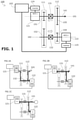
- the power transmission system 100 includes, as illustrated in Fig. 1 , a first power source 121, a second power source 122, a first input/output shaft 141, a first reduction gear 111, a second reduction gear 112, a first clutch 131, and a second clutch 132.
- the first reduction gear 111 and the second reduction gear 112 have two common rotation center axes, a first rotation center axis 101 and a second rotation center axis 102.
- the first reduction gear 111 is configured to include a sprocket 151 on the first rotation center axis 101 on the high-speed side, a sprocket 152 on the second rotation center axis 102 on the low-speed side, and a chain passed around the sprocket 151 and the sprocket 152.
- the second reduction gear 112 is configured to include a sprocket 154 on the second rotation center axis 102 on the high-speed side, a sprocket 155 on the first rotation center axis 101 on the low-speed side, and a chain passed around the sprocket 154 and the sprocket 155.
- the first power source 121 is configured as an electric motor driven by an inverter circuit 124 and coupled to the high-speed side of the first reduction gear 111 on the first rotation center axis 101.
- the second power source 122 is configured as an electric motor driven by an inverter circuit 125 and coupled to the high-speed side of the second reduction gear 112 on the second rotation center axis 102.
- the inverter circuits 124 and 125 are controlled by a controller 103.
- the first input/output shaft 141 is coupled to the low-speed side of the second reduction gear 112 on the first rotation center axis 101.
- the high-speed side of the first reduction gear 111 is coupled to the low-speed side of the second reduction gear 112 on the first rotation center axis 101 via the first clutch 131, and the low-speed side of the first reduction gear 111 is coupled to the high-speed side of the second reduction gear 112 on the second rotation center axis 102 via the second clutch 132.
- the first clutch 131 is configured as a one-way clutch that transmits the torque only from the low-speed side of the second reduction gear 112 to the high-speed side of the first reduction gear 111.
- the second clutch 132 is configured as a one-way clutch that transmits the torque only from the low-speed side of the first reduction gear 111 to the high-speed side of the second reduction gear 112.
- the drive power of the first power source 121 is transmitted in the order of the high-speed side of the first reduction gear 111, the low-speed side of the first reduction gear 111, the second clutch 132, the high-speed side of the second reduction gear 112, the low-speed side of the second reduction gear 112, and the first input/output shaft 141, as illustrated in Fig. 2A .
- the drive power of the first power source 121 can be reinforced by driving the second power source 122 with a matching rpm.
- the drive power of the second power source 122 is transmitted in the order of the high-speed side of the second reduction gear 112, the low-speed side of the second reduction gear 112, and the first input/output shaft 141, as illustrated in Fig. 2B .
- the torque is transmitted to the first power source 121, too, because the rotation on the low-speed side of the second reduction gear 112 is transmitted to the high-speed side of the first reduction gear 111 via the first clutch 131.
- the first power source 121 set in an idle state, no drive power is consumed.
- the rotation of the first input/output shaft 141 is transmitted in the order of the low-speed side of the second reduction gear 112, the first clutch 131, the high-speed side of the first reduction gear 111, and the first power source 121, as well as transmitted in the order of the low-speed side of the second reduction gear 112, the high-speed side of the second reduction gear 112, and the second power source 122, as illustrated in Fig. 2C .
- braking can be applied to the rotation of the first input/output shaft 141 by generating power by one or both of the first power source 121 and the second power source 122.
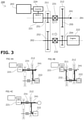
- the power transmission system 200 is suitable for applications where the drive power of an internal combustion engine is assisted by an electric motor for energy recovery during the braking.
- this embodiment has the same structure as that of the power transmission system 100 of the first embodiment except that the second power source 222 is configured as an internal combustion engine and does not include an inverter circuit, and therefore the description thereof will be omitted (reference numerals in the 200s are used with the same lower two digits).
- the drive power of the second power source 222 that is an internal combustion engine is transmitted in the order of the high-speed side of the second reduction gear 212, the low-speed side of the second reduction gear 212, and the first input/output shaft 241, as illustrated in Fig. 4A .
- the torque is transmitted to the first power source 221 that is an electric motor, too, because the rotation on the low-speed side of the second reduction gear 212 is transmitted to the high-speed side of the first reduction gear 211 via the first clutch 231.
- the first power source 221 that is an electric motor set in an idle state no drive power is consumed. If there is a surplus in the drive power of the second power source 222 that is an internal combustion engine, this may be used to generate power by the first power source 221 that is an electric motor.
- the drive power of the first power source 221 is transmitted in the order of the high-speed side of the first reduction gear 211, the low-speed side of the first reduction gear 211, the second clutch 232, the high-speed side of the second reduction gear 212, the low-speed side of the second reduction gear 212, and the first input/output shaft 241, as illustrated in Fig. 4B .
- the high-speed side of the second reduction gear 212 is coupled to the second power source 222, and therefore, the drive power of the second power source 222 that is an internal combustion engine can be assisted by the drive power of the first power source 221 that is an electric motor, by controlling and driving the first power source 221 such as to match with the rpm of the second power source 222.
- the rotation of the first input/output shaft 241 is transmitted in the order of the low-speed side of the second reduction gear 212, the high-speed side of the second reduction gear 212, and the second power source 222, as illustrated in Fig. 4C , so that engine braking by the second power source 222 that is an internal combustion engine is applied.
- the braking can be further assisted by generating power by the first power source 221 that is an electric motor.
- a power transmission system 200B according to a first variation example of the second embodiment of the present invention is configured to include a third clutch 233 between the second power source 222 that is an internal combustion engine and the high-speed side of the second reduction gear 212, to allow rotation transmission only from the second power source 222 that is an internal combustion engine to the high-speed side of the second reduction gear 212, as illustrated in Fig. 5 .
- Other configurations are the same as those of the power transmission system 200 of the second embodiment.
- braking on the rotation of the first input/output shaft 241 is applied only by the power generation by the first power source 221 that is an electric motor so that energy loss caused by engine braking can be reduced.
- More detailed control may be performed by configuring the system such that the controller 203 can control the On/Off or slip of the first clutch 231 and the second clutch 232.
- a power transmission system 200C according to a second variation example of the second embodiment of the present invention includes, as illustrated in Fig. 6 , a third power source 223 that is an electric motor driven by an inverter circuit 226 and coupled to the low-speed side of the first reduction gear 211 on the second rotation center axis 202.
- Other configurations are the same as those of the power transmission system 200B according to the first variation example of the second embodiment.
- the first power source 221 that is an electric motor and the third power source 223 that is an electric motor are directly connected to the high-speed side and the low-speed side of the first reduction gear 211 and rotated always simultaneously at different rpms.
- clutches are one-way clutches and switch among various modes without any control from outside
- clutches that allow On/Off control or slip control by the controller 103 may be adopted to enable switching among a wider variety of modes and to enable smoother transition between modes.
- the reduction gears may be any drive systems that use belts, toothed wheels, hydraulic pressure, etc., or a combination of these, as opposed to the chain drive system in the embodiments above.
Landscapes
- Engineering & Computer Science (AREA)
- Mechanical Engineering (AREA)
- Transportation (AREA)
- Chemical & Material Sciences (AREA)
- Combustion & Propulsion (AREA)
- Power Engineering (AREA)
- General Engineering & Computer Science (AREA)
- Life Sciences & Earth Sciences (AREA)
- Sustainable Development (AREA)
- Sustainable Energy (AREA)
- Hybrid Electric Vehicles (AREA)
- Electric Propulsion And Braking For Vehicles (AREA)
Abstract
Description
- The present invention relates to a power transmission system with at least two power sources including a first power source and a second power source, at least one input/output shaft including a first input/output shaft, two reduction gears including a first reduction gear and a second reduction gear, and at least two clutches including a first clutch and a second clutch.
- Power transmission systems with a plurality of power sources such as an internal combustion engine and an electric motor for driving an input/output shaft or performing energy recovery or the like through a plurality of reduction gears and clutches, such as the power transmission system of hybrid automobiles, have commonly been known.
- Various structures for the arrangement of the plurality of power sources, reduction gears, and clutches of the power transmission system have been proposed, from a complex design having a multi-stage planetary gear system, for example, to a simple design in which a plurality of drive sources are coupled together coaxially. Likewise, various control methods of the plurality of power sources, reduction gears, and clutches have been proposed in relation to the structures.
- For example, a power transmission system for hybrid automobiles such as the one described in
Patent Literature 1 is known, in which the structure and control are so simplified that control of other parts than the engine and the (electric) motor is made unnecessary. - The power transmission system described in Patent Literature 1 (see
Fig. 1 of Patent Literature 1) has a differential gear unit (22) between a first motor (16) and an engine (20), with a first one-way clutch (26) disposed between this differential gear unit (22) and the engine (20), and a second one-way clutch (28) disposed inside the differential gear unit (22). - The differential gear unit (22) is made up of a first drive pinion bevel gear (32) coupled to the engine (20) via the first one-way clutch (26), a second drive pinion bevel gear (34) having one end coupled to this first drive pinion bevel gear (32) via the second one-way clutch (28) and the other end coupled to the first motor (16), first and second driven bevel gears (36, 38) that operate in engagement with these first and second drive pinion bevel gears (32, 34), and a carrier (40) joining these first and second driven bevel gears (36, 38) to transmit the power from the first and second drive pinion bevel gears (32, 34) to the driven reduction gear (24) .
- The rotation of the driven reduction gear (24) is transmitted to an axle (30), and a second motor (18) is coupled to the axle (30).
- The first one-way clutch (26) is configured to transmit the rotation of the engine (20) only in the direction in which the first drive pinion bevel gear (32) rotates clockwise, while the second one-way clutch (28) is configured to transmit the rotation of the second drive pinion bevel gear (34) only in the direction in which the first drive pinion bevel gear (32) rotates clockwise.
- When the second drive pinion bevel gear (34) is rotated clockwise by driving the first motor (16), this power is transmitted only as far as to the first drive pinion bevel gear (32) and not to the engine (20).
- The engine (20) rotates clockwise, and when it rotates faster than the first motor (16), this power is transmitted only as far as to the first drive pinion bevel gear (32) and not to the second drive pinion bevel gear (34) and the first motor (16).
- Various patterns of control of drive and energy recovery are possible by controlling the first motor (16), engine (20), and second motor (18).
- [Patent Literature 1]
Japanese Patent No. 4355444 - In the power transmission system known from
Patent Literature 1 described above, the differential gear unit (22) is directly rotated by the rotation of the engine and the (electric) motor, meaning that the first and second driven bevel gears (36, 38) rotatably supported on the carrier are revolved at high speed. - One problem was that the system could hardly be made smaller because of the need to secure sufficient rigidity and strength for the differential gear unit (22) to preform differential operations correctly while rotating at high speed.
- Moreover, since the reduction gear consists only of the differential system, size reduction was difficult if a larger reduction ratio was to be achieved.
- Another issue is that the differential gear unit (22) that rotates at high speed and can hardly be made smaller has a large rotational moment of inertia, which lowers the responsiveness to changes in rpm.
- The first drive pinion bevel gear (32) and the second drive pinion bevel gear, and the first driven bevel gear (36) and the second driven bevel gear do not rotate relative to each other when driven by both of the first motor (16) and the engine (20). This led to another issue of poor durability caused by uneven wear on gear teeth surfaces because the same teeth stay continuously meshed with each other.
- The present invention solves these problems, its object being to provide a simple-structured power transmission system that allows easy size reduction and offers excellent responsiveness.
- The present invention solves the problems described above by providing a power transmission system including: at least two power sources including a first power source and a second power source; at least one input/output shaft including a first input/output shaft; two reduction gears including a first reduction gear and a second reduction gear; and at least two clutches including a first clutch and a second clutch, the first reduction gear and the second reduction gear having at least two common rotation center axes including a first rotation center axis and a second rotation center axis, the first power source being coupled to a high-speed side of the first reduction gear on the first rotation center axis, the second power source being coupled to a high-speed side of the second reduction gear on the second rotation center axis, the first input/output shaft being coupled to a low-speed side of the second reduction gear on the first rotation center axis, the high-speed side of the first reduction gear being coupled to the low-speed side of the second reduction gear on the first rotation center axis via the first clutch, and a low-speed side of the first reduction gear being coupled to the high-speed side of the second reduction gear on the second rotation center axis via the second clutch.
- In the power transmission system according to the invention set forth in
claim 1, the first reduction gear and the second reduction gear have at least two common rotation center axes including a first rotation center axis and a second rotation center axis; the first power source is coupled to a high-speed side of the first reduction gear on the first rotation center axis; the second power source is coupled to a high-speed side of the second reduction gear on the second rotation center axis; the first input/output shaft is coupled to a low-speed side of the second reduction gear on the first rotation center axis; the high-speed side of the first reduction gear is coupled to the low-speed side of the second reduction gear on the first rotation center axis via the first clutch; and the low-speed side of the first reduction gear is coupled to the high-speed side of the second reduction gear on the second rotation center axis via the second clutch. The power sources, input/output shaft, and clutches are all gathered together on the two rotation center axes, and can be arranged in a compact manner, which makes size reduction easy. - Also, having two reduction gears allows a small system to achieve a large reduction ratio.
- The two rotation center axes being arranged in parallel help realize simple-structured reduction gears and enable size reduction, as well as help reduce the rotational moment of inertia, which allows the system to offer excellent responsiveness.
- Moreover, the reduction gears rotate constantly relative to each other so that the wear is made even and the durability is improved.
- According to the configuration set forth in
claim 2, at least one of the two reduction gears is configured by a sprocket and a chain. This means that the distance between the two rotation center axes can be set freely, which increases the degree of freedom in the arrangement of the power sources and input/output shaft. - According to the configuration set forth in
claim 3, at least one of the at least two clutches is a one-way clutch. Clutch control from outside is therefore not necessary, and power distribution control is possible only through rotation control of the power sources. - According to the configuration set forth in claim 4, the at least two power sources include at least one electric motor. This increases the responsiveness in the drive control and enables regenerative control during braking.
- According to the configuration set forth in claim 5, the at least two power sources include at least one internal combustion engine, which means the power transmission system is applicable to a hybrid automobile.
- According to the configuration set forth in claim 6, a third power source is coupled to a low-speed side of the first reduction gear on the second rotation center axis via a third clutch. Three power sources can thus be used without making the power transmission system itself larger or more complex.
-
- [
Fig. 1] Fig. 1 is an illustrative diagram of apower transmission system 100 according to a first embodiment of the present invention. - [
Fig. 2] Fig. 2 is an illustrative diagram of the operation of thepower transmission system 100 according to the first embodiment of the present invention. - [
Fig. 3] Fig. 3 is an illustrative diagram of apower transmission system 200 according to a second embodiment of the present invention. - [
Fig. 4] Fig. 4 is an illustrative diagram of the operation of thepower transmission system 200 according to the second embodiment of the present invention. - [
Fig. 5] Fig. 5 is an illustrative diagram of apower transmission system 200B according to a first variation example of the second embodiment of the present invention. - [
Fig. 6] Fig. 6 is an illustrative diagram of apower transmission system 200C according to a second variation example of the second embodiment of the present invention. - A power transmission system according to the present invention will be hereinafter described with reference to the drawings.
- The
power transmission system 100 according to the first embodiment of the present invention includes, as illustrated inFig. 1 , afirst power source 121, asecond power source 122, a first input/output shaft 141, afirst reduction gear 111, asecond reduction gear 112, afirst clutch 131, and asecond clutch 132. - The
first reduction gear 111 and thesecond reduction gear 112 have two common rotation center axes, a firstrotation center axis 101 and a secondrotation center axis 102. - The
first reduction gear 111 is configured to include asprocket 151 on the firstrotation center axis 101 on the high-speed side, asprocket 152 on the secondrotation center axis 102 on the low-speed side, and a chain passed around thesprocket 151 and thesprocket 152. - The
second reduction gear 112 is configured to include asprocket 154 on the secondrotation center axis 102 on the high-speed side, asprocket 155 on the firstrotation center axis 101 on the low-speed side, and a chain passed around thesprocket 154 and thesprocket 155. - The
first power source 121 is configured as an electric motor driven by aninverter circuit 124 and coupled to the high-speed side of thefirst reduction gear 111 on the firstrotation center axis 101. - The
second power source 122 is configured as an electric motor driven by aninverter circuit 125 and coupled to the high-speed side of thesecond reduction gear 112 on the secondrotation center axis 102. - The
inverter circuits controller 103. The first input/output shaft 141 is coupled to the low-speed side of thesecond reduction gear 112 on the firstrotation center axis 101. - The high-speed side of the
first reduction gear 111 is coupled to the low-speed side of thesecond reduction gear 112 on the firstrotation center axis 101 via thefirst clutch 131, and the low-speed side of thefirst reduction gear 111 is coupled to the high-speed side of thesecond reduction gear 112 on the secondrotation center axis 102 via thesecond clutch 132. - The
first clutch 131 is configured as a one-way clutch that transmits the torque only from the low-speed side of thesecond reduction gear 112 to the high-speed side of thefirst reduction gear 111. - Therefore, when the rotation speed on the high-speed side of the
first reduction gear 111 is higher than that of the low-speed side of thesecond reduction gear 112, no torque transmission occurs. - The
second clutch 132 is configured as a one-way clutch that transmits the torque only from the low-speed side of thefirst reduction gear 111 to the high-speed side of thesecond reduction gear 112. - Therefore, when the rotation speed on the high-speed side of the
second reduction gear 112 is higher than that of the low-speed side of thefirst reduction gear 111, no torque transmission occurs. - By adopting one-way clutches that transmit torque only in one way in both forward and reverse directions (referred to as "bidirectional one-way clutch" or "two-way clutch", etc.), the same power transmission effect will be achieved in both forward and reverse directions.
- The operation of the
power transmission system 100 configured as described above is now explained. - When transmitting a rotation torque to the first input/
output shaft 141 by driving thefirst power source 121, the drive power of thefirst power source 121 is transmitted in the order of the high-speed side of thefirst reduction gear 111, the low-speed side of thefirst reduction gear 111, thesecond clutch 132, the high-speed side of thesecond reduction gear 112, the low-speed side of thesecond reduction gear 112, and the first input/output shaft 141, as illustrated inFig. 2A . - At this time, the torque is transmitted to the
second power source 122, too, because the high-speed side of thesecond reduction gear 112 and thesecond power source 122 are coupled together. However, with thesecond power source 122 set in an idle state, no drive power is consumed. - Alternatively, the drive power of the
first power source 121 can be reinforced by driving thesecond power source 122 with a matching rpm. - When transmitting a rotation torque to the first input/
output shaft 141 by driving thesecond power source 122, the drive power of thesecond power source 122 is transmitted in the order of the high-speed side of thesecond reduction gear 112, the low-speed side of thesecond reduction gear 112, and the first input/output shaft 141, as illustrated inFig. 2B . - At this time, the torque is transmitted to the
first power source 121, too, because the rotation on the low-speed side of thesecond reduction gear 112 is transmitted to the high-speed side of thefirst reduction gear 111 via thefirst clutch 131. However, with thefirst power source 121 set in an idle state, no drive power is consumed. - When transmitting a rotation torque of the first input/
output shaft 141 to thefirst power source 121 or thesecond power source 122, the rotation of the first input/output shaft 141 is transmitted in the order of the low-speed side of thesecond reduction gear 112, thefirst clutch 131, the high-speed side of thefirst reduction gear 111, and thefirst power source 121, as well as transmitted in the order of the low-speed side of thesecond reduction gear 112, the high-speed side of thesecond reduction gear 112, and thesecond power source 122, as illustrated inFig. 2C . - At this time, braking can be applied to the rotation of the first input/
output shaft 141 by generating power by one or both of thefirst power source 121 and thesecond power source 122. - These operations can be performed only by controlling the drive and energy recovery of the
first power source 121 and thesecond power source 122 by thecontroller 103, and there is no need to operate other systems. - The
power transmission system 200 according to a second embodiment of the present invention is suitable for applications where the drive power of an internal combustion engine is assisted by an electric motor for energy recovery during the braking. As illustrated inFig. 3 , this embodiment has the same structure as that of thepower transmission system 100 of the first embodiment except that thesecond power source 222 is configured as an internal combustion engine and does not include an inverter circuit, and therefore the description thereof will be omitted (reference numerals in the 200s are used with the same lower two digits). - The operation of the
power transmission system 200 is now explained. - When transmitting a rotation torque to the first input/
output shaft 241 by driving only thesecond power source 222 that is an internal combustion engine, the drive power of thesecond power source 222 that is an internal combustion engine is transmitted in the order of the high-speed side of thesecond reduction gear 212, the low-speed side of thesecond reduction gear 212, and the first input/output shaft 241, as illustrated inFig. 4A . - At this time, the torque is transmitted to the
first power source 221 that is an electric motor, too, because the rotation on the low-speed side of thesecond reduction gear 212 is transmitted to the high-speed side of thefirst reduction gear 211 via thefirst clutch 231. - However, with the
first power source 221 that is an electric motor set in an idle state, no drive power is consumed. If there is a surplus in the drive power of thesecond power source 222 that is an internal combustion engine, this may be used to generate power by thefirst power source 221 that is an electric motor. - When transmitting a rotation torque to the first input/
output shaft 241 by driving thefirst power source 221 that is an electric motor to assist the drive power of thesecond power source 222 that is an internal combustion engine, the drive power of thefirst power source 221 is transmitted in the order of the high-speed side of thefirst reduction gear 211, the low-speed side of thefirst reduction gear 211, thesecond clutch 232, the high-speed side of thesecond reduction gear 212, the low-speed side of thesecond reduction gear 212, and the first input/output shaft 241, as illustrated inFig. 4B . - At this time, the high-speed side of the
second reduction gear 212 is coupled to thesecond power source 222, and therefore, the drive power of thesecond power source 222 that is an internal combustion engine can be assisted by the drive power of thefirst power source 221 that is an electric motor, by controlling and driving thefirst power source 221 such as to match with the rpm of thesecond power source 222. - When applying braking to the rotation of the first input/
output shaft 241, the rotation of the first input/output shaft 241 is transmitted in the order of the low-speed side of thesecond reduction gear 212, the high-speed side of thesecond reduction gear 212, and thesecond power source 222, as illustrated inFig. 4C , so that engine braking by thesecond power source 222 that is an internal combustion engine is applied. - Since the rotation is also transmitted in the order of the low-speed side of the
second reduction gear 212, thefirst clutch 231, the high-speed side of thefirst reduction gear 211, and thefirst power source 221, the braking can be further assisted by generating power by thefirst power source 221 that is an electric motor. - A
power transmission system 200B according to a first variation example of the second embodiment of the present invention is configured to include a third clutch 233 between thesecond power source 222 that is an internal combustion engine and the high-speed side of thesecond reduction gear 212, to allow rotation transmission only from thesecond power source 222 that is an internal combustion engine to the high-speed side of thesecond reduction gear 212, as illustrated inFig. 5 . Other configurations are the same as those of thepower transmission system 200 of the second embodiment. - With the
power transmission system 200B according to this first variation example, braking on the rotation of the first input/output shaft 241 is applied only by the power generation by thefirst power source 221 that is an electric motor so that energy loss caused by engine braking can be reduced. - These operations can be performed only by controlling the drive and energy recovery of the
first power source 221 by thecontroller 203, and there is no need to operate other systems. - More detailed control may be performed by configuring the system such that the
controller 203 can control the On/Off or slip of thefirst clutch 231 and thesecond clutch 232. - A
power transmission system 200C according to a second variation example of the second embodiment of the present invention includes, as illustrated inFig. 6 , athird power source 223 that is an electric motor driven by aninverter circuit 226 and coupled to the low-speed side of thefirst reduction gear 211 on the secondrotation center axis 202. Other configurations are the same as those of thepower transmission system 200B according to the first variation example of the second embodiment. - In the
power transmission system 200B according to this first variation example, thefirst power source 221 that is an electric motor and thethird power source 223 that is an electric motor are directly connected to the high-speed side and the low-speed side of thefirst reduction gear 211 and rotated always simultaneously at different rpms. - This enables optimal distribution of the drive and energy recovery to the two electric motors by the
controller 203, which in turn enables a further improvement in drive efficiency and regeneration efficiency. - While embodiments of the present invention have been described above in detail, the present invention is not limited to the embodiments described above. Various design changes may be made without departing from the scope of the present invention set forth in the claims.
- For example, as opposed to the configuration of the embodiments above in which the clutches are one-way clutches and switch among various modes without any control from outside, clutches that allow On/Off control or slip control by the
controller 103 may be adopted to enable switching among a wider variety of modes and to enable smoother transition between modes. - While the power sources that are electric motors are driven by inverter circuits in the embodiments above, any types of electric motor may be used.
- The reduction gears may be any drive systems that use belts, toothed wheels, hydraulic pressure, etc., or a combination of these, as opposed to the chain drive system in the embodiments above.
-
- 100, 200 Power transmission system
- 101, 201 First rotation center axis
- 102, 202 Second rotation center axis
- 103, 203 Controller
- 111, 211 First reduction gear
- 112, 212 Second reduction gear
- 121, 221 First power source
- 122, 222 Second power source
- 223 Third power source
- 124, 224 Inverter circuit (of the first power source)
- 125 Inverter circuit (of the second power source)
- 226 Inverter circuit (of the second power source)
- 131, 231 First clutch
- 132, 232 Second clutch
- 233 Third clutch
- 141, 241 First input/output shaft
- 151, 251 Sprocket (on the high-speed side of the first reduction gear)
- 152, 252 Sprocket (on the low-speed side of the first reduction gear)
- 154, 254 Sprocket (on the high-speed side of the second reduction gear)
- 155, 255 Sprocket (on the low-speed side of the second reduction gear)
Claims (6)
- A power transmission system comprising: at least two power sources including a first power source and a second power source; at least one input/output shaft including a first input/output shaft; two reduction gears including a first reduction gear and a second reduction gear; and at least two clutches including a first clutch and a second clutch,the first reduction gear and the second reduction gear having at least two common rotation center axes including a first rotation center axis and a second rotation center axis,the first power source being coupled to a high-speed side of the first reduction gear on the first rotation center axis,the second power source being coupled to a high-speed side of the second reduction gear on the second rotation center axis,the first input/output shaft being coupled to a low-speed side of the second reduction gear on the first rotation center axis,the high-speed side of the first reduction gear being coupled to the low-speed side of the second reduction gear on the first rotation center axis via the first clutch, anda low-speed side of the first reduction gear being coupled to the high-speed side of the second reduction gear on the second rotation center axis via the second clutch.
- The power transmission system according to claim 1, wherein at least one of the two reduction gears is configured by a sprocket and a chain.
- The power transmission system according to claim 1 or 2, wherein at least one of the at least two clutches is a one-way clutch.
- The power transmission system according to any one of claims 1 to 3, wherein the at least two power sources include at least one electric motor.
- The power transmission system according to claim 4, wherein the at least two power sources include at least one internal combustion engine.
- The power transmission system according to any one of claims 1 to 5, further comprising a third power source coupled to the low-speed side of the first reduction gear on the second rotation center axis via a third clutch.
Applications Claiming Priority (2)
| Application Number | Priority Date | Filing Date | Title |
|---|---|---|---|
| JP2019092617A JP6784930B1 (en) | 2019-05-16 | 2019-05-16 | Power transmission mechanism |
| PCT/JP2020/001730 WO2020230368A1 (en) | 2019-05-16 | 2020-01-20 | Power transmission mechanism |
Publications (2)
| Publication Number | Publication Date |
|---|---|
| EP3971016A1 true EP3971016A1 (en) | 2022-03-23 |
| EP3971016A4 EP3971016A4 (en) | 2023-01-25 |
Family
ID=73219967
Family Applications (1)
| Application Number | Title | Priority Date | Filing Date |
|---|---|---|---|
| EP20804828.0A Withdrawn EP3971016A4 (en) | 2019-05-16 | 2020-01-20 | Power transmission mechanism |
Country Status (6)
| Country | Link |
|---|---|
| US (1) | US20220074469A1 (en) |
| EP (1) | EP3971016A4 (en) |
| JP (1) | JP6784930B1 (en) |
| KR (1) | KR20220010709A (en) |
| CN (1) | CN113518731A (en) |
| WO (1) | WO2020230368A1 (en) |
Families Citing this family (2)
| Publication number | Priority date | Publication date | Assignee | Title |
|---|---|---|---|---|
| US12109895B1 (en) * | 2020-09-24 | 2024-10-08 | Apple Inc. | Motion system |
| KR102732678B1 (en) * | 2022-12-30 | 2024-11-26 | 서영대학교 산학협력단 | Variable type Automatic transmission for Electric vehicle |
Family Cites Families (62)
| Publication number | Priority date | Publication date | Assignee | Title |
|---|---|---|---|---|
| US685756A (en) * | 1900-09-01 | 1901-11-05 | Charles H Gifford | Velocipede. |
| US707012A (en) * | 1900-10-31 | 1902-08-12 | Francis Arthur Rich | Velocipede driving-gear. |
| US1608141A (en) * | 1926-07-10 | 1926-11-23 | Harbig R Shekerjian | Bicycle |
| US1983827A (en) * | 1933-09-15 | 1934-12-11 | Winther Anthony | Transmission |
| US2463100A (en) * | 1947-12-19 | 1949-03-01 | Marcellus W Gredell | Two-speed automatic power transmission |
| US2694937A (en) * | 1950-09-15 | 1954-11-23 | Belle Ind Inc | Automatic transmission |
| US2641137A (en) * | 1951-08-28 | 1953-06-09 | Dale C Orcutt | Power transmission mechanism |
| US2916924A (en) * | 1955-07-19 | 1959-12-15 | Herbert H Johnson | Variable rotary power-transmitting apparatus |
| US2886977A (en) * | 1955-12-13 | 1959-05-19 | Carl Van Ausdall | Automatic transmission |
| US2809535A (en) * | 1956-07-25 | 1957-10-15 | Morse Chain Co | Clutch and controls therefor |
| US2866349A (en) * | 1957-05-27 | 1958-12-30 | Heckethorn Mfg & Supply Co | Variable speed drives for automotive generators |
| US3012445A (en) * | 1957-11-06 | 1961-12-12 | Borg Warner | Transmission |
| US2885896A (en) * | 1957-11-25 | 1959-05-12 | Curtiss Wright Corp | Plural speed driving mechanisms |
| US2964959A (en) * | 1957-12-06 | 1960-12-20 | Gen Motors Corp | Accessory drive transmission |
| US3017977A (en) * | 1958-01-27 | 1962-01-23 | Borg Warner | Transmission |
| US2911961A (en) * | 1958-08-04 | 1959-11-10 | Ford Motor Co | Engine accessory drive |
| US3124968A (en) * | 1962-02-01 | 1964-03-17 | Two-speed transmission mechanism for washing machine | |
| US3142202A (en) * | 1962-06-29 | 1964-07-28 | Muhlbeyer Josef | Two motor drive having a centrifugally controlled clutch |
| US3385497A (en) * | 1966-03-16 | 1968-05-28 | Philco Ford Corp | Drive means, particularly for tape players |
| US3444748A (en) * | 1967-02-01 | 1969-05-20 | Eaton Yale & Towne | Drive mechanism |
| US3436977A (en) * | 1968-01-02 | 1969-04-08 | Marcellus W Gredell | Two-speed automatic transmission |
| US3581853A (en) * | 1969-04-21 | 1971-06-01 | Hoffco Inc | Two-speed motor-bike drive |
| US3610062A (en) * | 1969-12-03 | 1971-10-05 | Hoffco Inc | Automatic mini-bike transmission |
| US3884089A (en) * | 1972-10-02 | 1975-05-20 | Fmc Corp | Multi-speed motion transmitting mechanism |
| US4276037A (en) * | 1979-04-23 | 1981-06-30 | Deere & Company | Load responsive drive mechanism |
| US4501575A (en) * | 1983-08-22 | 1985-02-26 | Lapeyre Fernand S | Multi-speed transmission for BMX bicycles and the like |
| US5055087A (en) * | 1990-11-29 | 1991-10-08 | Bourn & Koch Machine Tool Co. | Transmission for driving a machine tool spindle |
| JP3175423B2 (en) * | 1993-08-27 | 2001-06-11 | 株式会社エクォス・リサーチ | Drive mechanism in hybrid vehicle |
| US5827143A (en) * | 1996-12-11 | 1998-10-27 | Ntn Corporation | Two belt over-running clutch pulley |
| US6146296A (en) * | 1998-12-02 | 2000-11-14 | Apostolo; Mauricio C. | Multiple speed transmission for connecting an air conditioner compressor of a vehicle to the engine of the vehicle |
| KR100369135B1 (en) | 1999-12-28 | 2003-01-24 | 현대자동차주식회사 | Power transmit apparatus for hybrid electric vehicle |
| US6773367B2 (en) * | 2002-07-15 | 2004-08-10 | Case Corporation | Belt drive two speed shift mechanism |
| ITTO20030878A1 (en) * | 2003-11-05 | 2005-05-06 | Fiat Ricerche | MOTORCYCLE TRANSMISSION SYSTEM BETWEEN THE CRANKSHAFT OF A MOTOR WITH INTERNAL COMBUSTION OF A MOTOR VEHICLE AND A GROUP OF AUXILIARY DEVICES. |
| US7798928B2 (en) * | 2004-03-24 | 2010-09-21 | The Gates Corporation | Dual ratio belt drive system |
| US7100472B2 (en) * | 2004-03-24 | 2006-09-05 | General Motors Corporation | Two speed transfer case having two transfer chains |
| US7846051B2 (en) * | 2007-05-11 | 2010-12-07 | Gm Global Technology Operations, Inc. | Hybrid powertrain with an engine input clutch and method of control |
| TWI463085B (en) * | 2008-02-01 | 2014-12-01 | Tai Her Yang | Continuous variable transmission device with high shift transmission pulley train |
| US8808124B2 (en) * | 2008-04-15 | 2014-08-19 | GM Global Technology Operations LLC | Belt alternator starter systems for hybrid vehicles |
| US8216113B2 (en) * | 2008-05-27 | 2012-07-10 | Litens Automotive Partnership | Engine powered device having accessory drive and reversing motor for selectively starting engine and powering accessory drive |
| DE202008011202U1 (en) * | 2008-08-22 | 2009-01-29 | Kendrion Linnig Gmbh | Reibschaltkupplung with one of a drive motor via a drive belt driven drive wheel and drive unit |
| US8313400B2 (en) * | 2008-11-13 | 2012-11-20 | The Gates Corporation | Damped isolator |
| JP5094687B2 (en) * | 2008-11-18 | 2012-12-12 | キヤノン株式会社 | Drive transmission device |
| JP5420234B2 (en) * | 2008-12-08 | 2014-02-19 | 現代自動車株式会社 | V-belt drive type motor generator device |
| US9169909B2 (en) * | 2009-11-24 | 2015-10-27 | Tai-Her Yang | Stepless variable transmission device with parallel low gear wheel group |
| JP5492990B2 (en) * | 2010-06-15 | 2014-05-14 | 本田技研工業株式会社 | Car drive system |
| JP5136660B2 (en) * | 2010-07-08 | 2013-02-06 | 株式会社デンソー | Power transmission device for vehicle |
| JP2012147598A (en) * | 2011-01-13 | 2012-08-02 | Toyota Motor Corp | Driving apparatus |
| CN103477119B (en) * | 2011-04-11 | 2016-03-02 | 利滕斯汽车合伙公司 | For by transmission of power to the multi-speed transmission of load |
| CN202147580U (en) * | 2011-07-19 | 2012-02-22 | 东风汽车公司 | Double motor driven driving system of hybrid power automobile |
| ITBO20120363A1 (en) * | 2012-07-03 | 2014-01-04 | Ferrari Spa | AUTOMATIC MANUAL TRANSMISSION FOR A HYBRID CAR PROVIDED WITH AN INTERNAL COMBUSTION ENGINE AND AN ELECTRIC MACHINE |
| JP5896858B2 (en) * | 2012-08-02 | 2016-03-30 | アイシン精機株式会社 | Hybrid drive unit |
| EP2937237B1 (en) * | 2012-12-21 | 2021-08-11 | Nissan Motor Co., Ltd. | Hybrid vehicle drive device |
| DE102014119210A1 (en) * | 2014-12-19 | 2016-06-23 | Rolls-Royce Deutschland Ltd & Co Kg | Method for determining a fuel leak of a fuel system of an aircraft having at least two engines |
| BR112018000279B1 (en) * | 2015-07-08 | 2023-03-21 | Agco Corporation | TRANSMISSION SYSTEM BY BELT AND VEHICLE |
| JP2018534492A (en) * | 2015-09-17 | 2018-11-22 | ダナ リミテッド | Hybrid electric powertrain configuration with ball variator continuously variable transmission used as power split |
| US10760650B2 (en) * | 2015-09-24 | 2020-09-01 | Cummins Inc. | Gear mechanism providing passive ratio switching |
| JP6524453B2 (en) * | 2015-09-30 | 2019-06-05 | ジヤトコ株式会社 | Power train |
| CN107264260A (en) * | 2016-04-06 | 2017-10-20 | 北京汽车动力总成有限公司 | A kind of hybrid electric drive system and automobile |
| JP2018069801A (en) * | 2016-10-25 | 2018-05-10 | スズキ株式会社 | Drive device of hybrid vehicle |
| JP6658685B2 (en) * | 2017-07-05 | 2020-03-04 | トヨタ自動車株式会社 | Series type hybrid drive |
| CN109591576A (en) * | 2017-09-30 | 2019-04-09 | 比亚迪股份有限公司 | Hybrid electric drive system and vehicle |
| US11052747B2 (en) * | 2018-05-04 | 2021-07-06 | Deere & Company | Multi-mode powertrains |
-
2019
- 2019-05-16 JP JP2019092617A patent/JP6784930B1/en active Active
-
2020
- 2020-01-20 KR KR1020217029586A patent/KR20220010709A/en not_active Abandoned
- 2020-01-20 EP EP20804828.0A patent/EP3971016A4/en not_active Withdrawn
- 2020-01-20 CN CN202080017834.7A patent/CN113518731A/en not_active Withdrawn
- 2020-01-20 WO PCT/JP2020/001730 patent/WO2020230368A1/en not_active Ceased
-
2021
- 2021-11-15 US US17/526,140 patent/US20220074469A1/en not_active Abandoned
Also Published As
| Publication number | Publication date |
|---|---|
| JP6784930B1 (en) | 2020-11-18 |
| US20220074469A1 (en) | 2022-03-10 |
| CN113518731A (en) | 2021-10-19 |
| EP3971016A4 (en) | 2023-01-25 |
| WO2020230368A1 (en) | 2020-11-19 |
| JP2020185934A (en) | 2020-11-19 |
| KR20220010709A (en) | 2022-01-26 |
Similar Documents
| Publication | Publication Date | Title |
|---|---|---|
| CN100523546C (en) | Electrically variable transmission having six fixed speed ratios | |
| EP2924317B1 (en) | Input synthesis gear system | |
| KR102440057B1 (en) | transmission for electric vehicles | |
| JP3837118B2 (en) | Vehicle power transmission mechanism with fuel cell power supply and multi-range transmission | |
| KR100704788B1 (en) | Hybrid car | |
| CN101312870A (en) | Electric drive system with multiple electric motors | |
| JP2015107788A (en) | Transmission for hybrid vehicle | |
| CN104653724B (en) | Hybrid power system for vehicle | |
| CN103238009A (en) | Reconfigurable Hybrid Powertrain | |
| JP2019050706A (en) | Drive unit for electric vehicle | |
| KR101558691B1 (en) | 2-motor type hybrid power train and hev-hv driving force mode switching method thereof | |
| CN108422850B (en) | Hybrid variable speed drive axle | |
| CN113602077A (en) | Hybrid power vehicle transmission device and transmission method thereof | |
| KR20090128660A (en) | Hybrid train powertrain | |
| KR20210089817A (en) | Device for torque vectoring | |
| US20220074469A1 (en) | Power transmission system | |
| KR101500205B1 (en) | Hybrid power train for vehicle | |
| KR100623648B1 (en) | Dual Clutch Transmission for Hybrid Electric Vehicles and Control Method by Mode | |
| JP2006298246A (en) | Drive unit for hybrid vehicle | |
| JPH09123773A (en) | Hybrid drive | |
| KR102575179B1 (en) | Power transmission system of vehicle | |
| US20080227576A1 (en) | Device for Power Transmission Between a Heat Engine Output and an Axle Shaft and Related Power Transmission Method | |
| CN110422044A (en) | Automobile and hybrid power system | |
| CN107310366B (en) | Double-motor high-low speed area composite double-speed driving assembly | |
| CN111572339B (en) | A pure electric transmission device, gearbox and vehicle |
Legal Events
| Date | Code | Title | Description |
|---|---|---|---|
| STAA | Information on the status of an ep patent application or granted ep patent |
Free format text: STATUS: THE INTERNATIONAL PUBLICATION HAS BEEN MADE |
|
| PUAI | Public reference made under article 153(3) epc to a published international application that has entered the european phase |
Free format text: ORIGINAL CODE: 0009012 |
|
| STAA | Information on the status of an ep patent application or granted ep patent |
Free format text: STATUS: REQUEST FOR EXAMINATION WAS MADE |
|
| 17P | Request for examination filed |
Effective date: 20211019 |
|
| AK | Designated contracting states |
Kind code of ref document: A1 Designated state(s): AL AT BE BG CH CY CZ DE DK EE ES FI FR GB GR HR HU IE IS IT LI LT LU LV MC MK MT NL NO PL PT RO RS SE SI SK SM TR |
|
| DAV | Request for validation of the european patent (deleted) | ||
| DAX | Request for extension of the european patent (deleted) | ||
| A4 | Supplementary search report drawn up and despatched |
Effective date: 20230103 |
|
| RIC1 | Information provided on ipc code assigned before grant |
Ipc: B60K 1/02 20060101ALN20221221BHEP Ipc: B60L 50/13 20190101ALI20221221BHEP Ipc: B60K 6/38 20071001ALI20221221BHEP Ipc: B60L 9/18 20060101ALI20221221BHEP Ipc: B60K 6/48 20071001ALI20221221BHEP Ipc: B60K 6/383 20071001ALI20221221BHEP Ipc: B60K 6/36 20071001ALI20221221BHEP Ipc: B60K 17/04 20060101ALI20221221BHEP Ipc: B60K 17/02 20060101ALI20221221BHEP Ipc: B60L 15/20 20060101AFI20221221BHEP |
|
| STAA | Information on the status of an ep patent application or granted ep patent |
Free format text: STATUS: THE APPLICATION IS DEEMED TO BE WITHDRAWN |
|
| 18D | Application deemed to be withdrawn |
Effective date: 20230801 |