EP3970982A1 - Printing apparatus - Google Patents
Printing apparatus Download PDFInfo
- Publication number
- EP3970982A1 EP3970982A1 EP21191000.5A EP21191000A EP3970982A1 EP 3970982 A1 EP3970982 A1 EP 3970982A1 EP 21191000 A EP21191000 A EP 21191000A EP 3970982 A1 EP3970982 A1 EP 3970982A1
- Authority
- EP
- European Patent Office
- Prior art keywords
- base material
- drive roller
- roller
- transparent base
- unit
- Prior art date
- Legal status (The legal status is an assumption and is not a legal conclusion. Google has not performed a legal analysis and makes no representation as to the accuracy of the status listed.)
- Pending
Links
- 238000007639 printing Methods 0.000 title claims abstract description 84
- 239000000463 material Substances 0.000 claims abstract description 188
- 238000001816 cooling Methods 0.000 claims abstract description 67
- 238000003384 imaging method Methods 0.000 claims abstract description 66
- 238000011144 upstream manufacturing Methods 0.000 claims abstract description 15
- 238000001035 drying Methods 0.000 claims description 43
- 239000000428 dust Substances 0.000 claims description 33
- 238000004804 winding Methods 0.000 claims description 26
- 239000000976 ink Substances 0.000 claims description 23
- 238000007664 blowing Methods 0.000 claims description 17
- 239000003507 refrigerant Substances 0.000 claims description 10
- 238000007689 inspection Methods 0.000 abstract description 22
- 230000008602 contraction Effects 0.000 abstract description 7
- 230000032258 transport Effects 0.000 description 37
- 238000001514 detection method Methods 0.000 description 30
- 230000007246 mechanism Effects 0.000 description 19
- 239000007788 liquid Substances 0.000 description 18
- 239000000498 cooling water Substances 0.000 description 12
- 230000004048 modification Effects 0.000 description 10
- 238000012986 modification Methods 0.000 description 10
- 239000011248 coating agent Substances 0.000 description 9
- 238000000576 coating method Methods 0.000 description 9
- 230000007547 defect Effects 0.000 description 7
- 239000003086 colorant Substances 0.000 description 6
- 238000007599 discharging Methods 0.000 description 6
- 230000006870 function Effects 0.000 description 6
- 238000010276 construction Methods 0.000 description 5
- 238000007641 inkjet printing Methods 0.000 description 5
- XLYOFNOQVPJJNP-UHFFFAOYSA-N water Substances O XLYOFNOQVPJJNP-UHFFFAOYSA-N 0.000 description 4
- 239000000853 adhesive Substances 0.000 description 3
- 230000001070 adhesive effect Effects 0.000 description 3
- 230000015556 catabolic process Effects 0.000 description 2
- 230000008878 coupling Effects 0.000 description 2
- 238000010168 coupling process Methods 0.000 description 2
- 238000005859 coupling reaction Methods 0.000 description 2
- 238000006731 degradation reaction Methods 0.000 description 2
- 238000010981 drying operation Methods 0.000 description 2
- 229920000139 polyethylene terephthalate Polymers 0.000 description 2
- 239000005020 polyethylene terephthalate Substances 0.000 description 2
- 230000002441 reversible effect Effects 0.000 description 2
- 239000002390 adhesive tape Substances 0.000 description 1
- 230000000295 complement effect Effects 0.000 description 1
- 238000004590 computer program Methods 0.000 description 1
- 238000009792 diffusion process Methods 0.000 description 1
- 230000000694 effects Effects 0.000 description 1
- 230000002708 enhancing effect Effects 0.000 description 1
- 238000007646 gravure printing Methods 0.000 description 1
- 239000002184 metal Substances 0.000 description 1
- 229910044991 metal oxide Inorganic materials 0.000 description 1
- 150000004706 metal oxides Chemical class 0.000 description 1
- 238000007645 offset printing Methods 0.000 description 1
- 239000005026 oriented polypropylene Substances 0.000 description 1
- -1 polyethylene terephthalate Polymers 0.000 description 1
- 239000002994 raw material Substances 0.000 description 1
- 239000011347 resin Substances 0.000 description 1
- 229920005989 resin Polymers 0.000 description 1
- 239000004065 semiconductor Substances 0.000 description 1
Images


Classifications
-
- B—PERFORMING OPERATIONS; TRANSPORTING
- B41—PRINTING; LINING MACHINES; TYPEWRITERS; STAMPS
- B41J—TYPEWRITERS; SELECTIVE PRINTING MECHANISMS, i.e. MECHANISMS PRINTING OTHERWISE THAN FROM A FORME; CORRECTION OF TYPOGRAPHICAL ERRORS
- B41J11/00—Devices or arrangements of selective printing mechanisms, e.g. ink-jet printers or thermal printers, for supporting or handling copy material in sheet or web form
- B41J11/0015—Devices or arrangements of selective printing mechanisms, e.g. ink-jet printers or thermal printers, for supporting or handling copy material in sheet or web form for treating before, during or after printing or for uniform coating or laminating the copy material before or after printing
- B41J11/002—Curing or drying the ink on the copy materials, e.g. by heating or irradiating
- B41J11/0022—Curing or drying the ink on the copy materials, e.g. by heating or irradiating using convection means, e.g. by using a fan for blowing or sucking air
-
- B—PERFORMING OPERATIONS; TRANSPORTING
- B41—PRINTING; LINING MACHINES; TYPEWRITERS; STAMPS
- B41J—TYPEWRITERS; SELECTIVE PRINTING MECHANISMS, i.e. MECHANISMS PRINTING OTHERWISE THAN FROM A FORME; CORRECTION OF TYPOGRAPHICAL ERRORS
- B41J11/00—Devices or arrangements of selective printing mechanisms, e.g. ink-jet printers or thermal printers, for supporting or handling copy material in sheet or web form
- B41J11/0015—Devices or arrangements of selective printing mechanisms, e.g. ink-jet printers or thermal printers, for supporting or handling copy material in sheet or web form for treating before, during or after printing or for uniform coating or laminating the copy material before or after printing
- B41J11/002—Curing or drying the ink on the copy materials, e.g. by heating or irradiating
-
- B—PERFORMING OPERATIONS; TRANSPORTING
- B41—PRINTING; LINING MACHINES; TYPEWRITERS; STAMPS
- B41J—TYPEWRITERS; SELECTIVE PRINTING MECHANISMS, i.e. MECHANISMS PRINTING OTHERWISE THAN FROM A FORME; CORRECTION OF TYPOGRAPHICAL ERRORS
- B41J11/00—Devices or arrangements of selective printing mechanisms, e.g. ink-jet printers or thermal printers, for supporting or handling copy material in sheet or web form
- B41J11/36—Blanking or long feeds; Feeding to a particular line, e.g. by rotation of platen or feed roller
- B41J11/42—Controlling printing material conveyance for accurate alignment of the printing material with the printhead; Print registering
-
- B—PERFORMING OPERATIONS; TRANSPORTING
- B41—PRINTING; LINING MACHINES; TYPEWRITERS; STAMPS
- B41J—TYPEWRITERS; SELECTIVE PRINTING MECHANISMS, i.e. MECHANISMS PRINTING OTHERWISE THAN FROM A FORME; CORRECTION OF TYPOGRAPHICAL ERRORS
- B41J15/00—Devices or arrangements of selective printing mechanisms, e.g. ink-jet printers or thermal printers, specially adapted for supporting or handling copy material in continuous form, e.g. webs
- B41J15/16—Means for tensioning or winding the web
-
- B—PERFORMING OPERATIONS; TRANSPORTING
- B41—PRINTING; LINING MACHINES; TYPEWRITERS; STAMPS
- B41J—TYPEWRITERS; SELECTIVE PRINTING MECHANISMS, i.e. MECHANISMS PRINTING OTHERWISE THAN FROM A FORME; CORRECTION OF TYPOGRAPHICAL ERRORS
- B41J29/00—Details of, or accessories for, typewriters or selective printing mechanisms not otherwise provided for
- B41J29/02—Framework
- B41J29/023—Framework with reduced dimensions
-
- B—PERFORMING OPERATIONS; TRANSPORTING
- B41—PRINTING; LINING MACHINES; TYPEWRITERS; STAMPS
- B41J—TYPEWRITERS; SELECTIVE PRINTING MECHANISMS, i.e. MECHANISMS PRINTING OTHERWISE THAN FROM A FORME; CORRECTION OF TYPOGRAPHICAL ERRORS
- B41J29/00—Details of, or accessories for, typewriters or selective printing mechanisms not otherwise provided for
- B41J29/17—Cleaning arrangements
-
- B—PERFORMING OPERATIONS; TRANSPORTING
- B41—PRINTING; LINING MACHINES; TYPEWRITERS; STAMPS
- B41J—TYPEWRITERS; SELECTIVE PRINTING MECHANISMS, i.e. MECHANISMS PRINTING OTHERWISE THAN FROM A FORME; CORRECTION OF TYPOGRAPHICAL ERRORS
- B41J29/00—Details of, or accessories for, typewriters or selective printing mechanisms not otherwise provided for
- B41J29/377—Cooling or ventilating arrangements
-
- B—PERFORMING OPERATIONS; TRANSPORTING
- B41—PRINTING; LINING MACHINES; TYPEWRITERS; STAMPS
- B41J—TYPEWRITERS; SELECTIVE PRINTING MECHANISMS, i.e. MECHANISMS PRINTING OTHERWISE THAN FROM A FORME; CORRECTION OF TYPOGRAPHICAL ERRORS
- B41J2/00—Typewriters or selective printing mechanisms characterised by the printing or marking process for which they are designed
- B41J2/005—Typewriters or selective printing mechanisms characterised by the printing or marking process for which they are designed characterised by bringing liquid or particles selectively into contact with a printing material
- B41J2/01—Ink jet
- B41J2/21—Ink jet for multi-colour printing
- B41J2/2107—Ink jet for multi-colour printing characterised by the ink properties
- B41J2/2114—Ejecting specialized liquids, e.g. transparent or processing liquids
- B41J2/2117—Ejecting white liquids
-
- B—PERFORMING OPERATIONS; TRANSPORTING
- B41—PRINTING; LINING MACHINES; TYPEWRITERS; STAMPS
- B41J—TYPEWRITERS; SELECTIVE PRINTING MECHANISMS, i.e. MECHANISMS PRINTING OTHERWISE THAN FROM A FORME; CORRECTION OF TYPOGRAPHICAL ERRORS
- B41J2203/00—Embodiments of or processes related to the control of the printing process
- B41J2203/01—Inspecting a printed medium or a medium to be printed using a sensing device
-
- B—PERFORMING OPERATIONS; TRANSPORTING
- B65—CONVEYING; PACKING; STORING; HANDLING THIN OR FILAMENTARY MATERIAL
- B65H—HANDLING THIN OR FILAMENTARY MATERIAL, e.g. SHEETS, WEBS, CABLES
- B65H2515/00—Physical entities not provided for in groups B65H2511/00 or B65H2513/00
- B65H2515/40—Temperature; Thermal conductivity
Definitions
- the present invention relates to a printing apparatus configured to print images, such as characters and figures, on an elongated base material.
- a currently-used printing apparatus includes a printing unit, a drying unit, and an image acquisition unit (imaging unit and illuminating unit).
- the printing unit includes inkjet heads.
- the heads eject inks to a transparent base material.
- the drying unit dries the inks by blowing warm air.
- the image acquisition unit captures a printed image. Defect inspection is performed based on the captured printed image. See, for example, Japanese Patent Publication No. 2019-142007A .
- a cooling mechanism is provided between the drying unit and the image acquisition unit (scanner) on a transportation path of a print medium.
- the cooling mechanism includes a plurality of cooling driven rollers (cooling rollers).
- the cooling driven rollers cool the print medium.
- the cooling driven rollers are each configured such that a refrigerant like water is supplied to one end of a rotary shaft thereof from a refrigerant supply device and is discharged from the other end of the rotary shaft, and then returns back into the refrigerant supply device. See, for example, Japanese Patent Publications No. 2020-011396A and No. 2018-122525A .
- the following three drawbacks arise when the base material heated by the drying unit is transported to the image acquisition unit (imaging unit and illuminating unit).
- the imaging unit is a contact image sensor (CIS)
- first drawback it becomes impossible to capture images if the temperature of the CIS rises to 70°C or more
- second drawback Increase in temperature of the illuminating unit causes reduced quantity of light, which may lead to degraded inspection quality due to different imaging results among the same pattern
- second drawback The degree of expansion and contraction of the base material due to the temperature is varied depending on types and patterns of the base material, which may cause erroneous detection (third drawback).
- a plurality of cooling driven rollers are provided between the drying unit and the imaging unit. This can make both the imaging unit itself and the base material near the imaging unit to be of a constant temperature. Moreover, this can suppress poor imaging and erroneous detection to some extent from a view point of the influence of temperatures.
- the cooling driven rollers are sometimes heavy since a refrigerant like water is supplied to the cooling driven rollers individually. Accordingly, inertia and rotational resistance of each of the cooling driven rollers increase. As a result, it becomes difficult to control tension on the base material, leading to possibility that a degree of expansion and contraction of the base material is unstable and inspection is performed inaccurately.
- the present invention has been made regarding the state of the art noted above, and its object is to provide a printing apparatus that can perform stable inspection of a base material while tension control is performed easily.
- One aspect of the present invention is a printing apparatus for printing an image on a base material, the printing apparatus including a printing unit configured to cause inks to adhere to the base material, a drying unit located downstream of the printing unit in a transportation direction of the base material and configured to dry the inks adhering to the base material with use of heat, an imaging unit located downstream of the drying unit in the transportation direction of the base material and configured to image the base material, a first drive roller located downstream of the drying unit and upstream of the imaging unit in the transportation direction of the base material and configured to apply a transportation force to the base material with a function of cooling the base material, and a second drive roller located downstream of the imaging unit in the transportation direction of the base material and configured to apply a transportation force to the base material.
- the first drive roller is located upstream of the imaging unit.
- the first drive roller can cool the base material. This prevents increase in temperature of the base material to a given value or more, which increase may cause poor imaging by the imaging unit. As a result, stable inspection can be maintained.
- a cooling driven roller is a driven roller having a cooling function and configured to apply no transportation force to the base material. With such a cooling driven roller, tension control on the base material may be difficult, and a degree of expansion and contraction of the base material may be unstable, leading to inaccurate inspection.
- the first drive roller having a cooling function is provided. With such a configuration, the roller itself has the cooling function, and a transportation force is applicable to the base material while a rotation speed of the roller is controlled. This enables stable and accurate inspection of the base material under appropriate tension control of the base material.
- first drive roller is located upstream of the imaging unit and the second drive roller is located downstream of the imaging unit
- tension on the base material that passes the imaging unit is easily controlled. That is, tension on the base material that passes the imaging unit is not affected by a load from a group of rollers containing the first drive roller and located upstream of the first drive roller. Accordingly, since control of the tension on the base material that passes the imaging unit (tension control by the second drive roller) is easily performed, degradation of the inspection accuracy due to expansion and contraction of the base material can be suppressed.
- the first drive roller of the printing apparatus described above cools the base material by supplying a refrigerant thereinto.
- the first drive roller can cool the base material with use of the refrigerant supplied thereinto.
- the first drive roller of the printing apparatus described above includes a gas-blowing unit, and cools the base material by blowing gas from the gas-blowing unit to a winding region of the base material wound on the first drive roller.
- the first drive roller can cool the base material with use of gas blown from the gas-blowing unit to the winding region of the base material.
- the printing apparatus described above further includes a cleaner that is located downstream of the first drive roller and upstream of the imaging unit in the transportation direction of the base material and is configured to remove dust attached to the base material. Accordingly, the imaging unit can capture images in such a condition where the cleaner removes dust. This can prevent erroneous determination of a printed region as defect due to the dust.
- the second drive roller is located above the first drive roller, the imaging unit is positioned higher in level than the first drive roller, and the second drive roller is positioned higher in level than the imaging unit. This causes upward transportation of the base material from the bottom in a transportation path between the first drive roller and the second drive roller. As a result, the footprint of the printing apparatus is suppressible.
- the imaging unit is formed by a contact image sensor. This prevents increase in temperature of the base material to a given value or more, which increase may cause poor imaging of the contact image sensor. As a result, stable inspection can be maintained.
- the printing apparatus according to the present invention can achieve easy tension control of the base material as well as stable and accurate inspection of the base material.
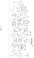
- Fig. 1 schematically illustrates a printing apparatus 1 according to the embodiment of the present invention.
- Fig. 2 illustrates an inspecting block 7 and a winding mechanism 12 according to the embodiment.
- the printing apparatus 1 includes a coating unit 2, a printing block 3, a drying block 5, an inspecting block 7, a feeding mechanism 11, and a winding mechanism 12.
- the feeding mechanism 11, the coating unit 2, the printing block 3, the drying block 5, the inspecting block 7, and the winding mechanism 12 are lined up in this order horizontally.
- upstream means an upstream side of a transportation path (or transportation direction) for transporting an elongated transparent base material M.
- downstream means a downstream side of the transportation path (or transportation direction).
- the printing apparatus 1 transports an elongated (or elongated strip) transparent base material (or transparent print medium) M from the feeding mechanism 11 to the winding mechanism 12 in a roll-to-roll manner.
- the raw material of the transparent base material M is a resin film such as oriented polypropylene (OPP) or polyethylene terephthalate (PET).
- OPP oriented polypropylene
- PET polyethylene terephthalate
- one of both faces of the transparent base material M on which images are printed is called a printing face F1
- the other opposite to the printing face F1 is called a rear face F2.
- the coating unit 2 applies a coating liquid to the transparent base material M to be transported. Thereafter, the printing block 3 ejects inks with an inkjet printing system to the transparent base material M to be transported for forming images on the transparent base material M.
- the drying block 5 dries the inks adhering to the transparent base material M to be transported.
- the inspecting block 7 performs defect inspection to the images printed on the transparent base material M to be transported.
- the printing apparatus 1 includes a controller 14 and a memory unit (e.g., memory) not shown.
- the controller 14 includes a central processing unit (CPU).
- the controller 14 controls components of the printing apparatus 1 (e.g., inspecting block 7 and winding mechanism 12).
- the memory unit stores computer programs necessary for operation of the printing apparatus 1.
- the coating unit 2 includes a drive roller 16, a plurality of transport rollers 18, a pan 21, and a gravure roller 23.
- the drive roller 16 is located adjacent to an inlet of the coating unit 2.
- the drive roller 16 takes the transparent base material M from the feeding mechanism 11.
- the drive roller 16 and the transport rollers 18 are each supported in a rotatable manner around a horizontal axis in a Y-direction.
- the drive roller 16 is driven by an electric motor.
- the transport rollers 18 are each not coupled with a rotary shaft of the electric motor, and applies no transportation force to the transparent base material M.
- the transport rollers 18 each guide the transparent base material M.
- the pan 21 stores a liquid primer (coating liquid).
- a lower portion of the gravure roller 23 is partially immersed in the primer stored in the pan 21.
- An upper portion of the gravure roller 23 contacts the transparent base material M to be transported.
- the gravure roller 23 is driven by an electric motor.
- the gravure roller 23 rotates in a direction opposite to the transportation direction of the transparent base material M.
- the primer is held on an outer circumferential face of the gravure roller 23, and the held primer is transferred to the transparent base material M. Accordingly, the primer is applied to the printing face F1 of the transparent base material M.
- the transparent base material M on which the primer is applied is transported to the printing block 3.
- the printing block 3 includes a plurality of transport rollers 18, a color printing unit 31, a first drying unit 32, a white color printing unit 33, and a second drying unit 34.
- the color printing unit 31, the first drying unit 32, the white color printing unit 33, and the second drying unit 34 are arranged in this order along the transportation path of the transparent base material M.
- the color printing unit 31 includes a plurality of (e.g., six) ejection heads 41.
- the six ejection heads 41 are arranged along the transportation path of the transparent base material M.
- the six ejection heads 41 and an ejection head 43 mentioned later are each arranged across the transparent base material M in a width direction (Y-direction) of the transparent base material M.
- the six ejection heads 41 eject colored inks other than white with an inkjet printing system.
- the six ejection heads 41 eject inks of cyan, magenta, yellow, black, blue, orange, for example, individually. Accordingly, color figures are formed on the printing face F1 of the transparent base material M.
- the first drying unit 32 includes a plurality of nozzles 42 arranged along the transportation path.
- the nozzles 42 and a plurality of nozzles 44 and 48 mentioned later include ejection ports individually elongated in the Y-direction.
- the ejection ports of the nozzles 42 and the nozzles 44 and 48 mentioned later are each arranged across the transparent base material M in the width direction (Y-direction) of the transparent base material M.
- the nozzles 42 each eject air at room temperatures, for example, that are generated by an electric fan. Accordingly, drying operation is performed for the inks of the six colors adhering to the printing face F1 of the transparent base material M.
- the white color printing unit 33 includes one ejection head 43.
- the ejection head 43 ejects a white ink with an inkjet printing system. Accordingly, a while color figure is formed on the printing face F1 of the transparent base material M.
- the second drying unit 34 includes a plurality of nozzles 44 arranged along the transportation direction.
- the nozzles 44 each eject air at room temperatures, for example, that are generated by an electric fan. Accordingly, drying operation is performed for the white ink adhering to the printing face F1 of the transparent base material M.
- the transparent base material M having passed the second drying unit 34 is transported to the drying block 5.
- the drying block 5 includes a plurality of (e.g., three) stages of drying paths DP1 to DP3, a plurality of transport rollers 18, two air turn bars 46, and a drying unit 47.
- the two air turn bars 46 each eject air from an ejection port, not shown.
- the two air turn bars 46 can fold the transparent base material M in a non-contact manner.
- the three stages of the drying paths DP1 to DP3 are arranged in an up-down direction, and are formed by an upper-stage drying path DP1, a middle-stage drying path DP2, and a lower-stage drying path DP3. That is, the transparent base material M is transported in the drying block 5 in an S-shaped manner.
- the transparent base material M is transported along the upper-stage drying path DP1 in a forward direction XF from the printing block 3 to the inspecting block 7, and is folded with the two transport rollers 18. Then, the transparent base material M is transported along the middle-stage drying path DP2 in a reverse direction XB from the inspecting block 7 to the printing block 3, and is folded with the two air turn bars 46 in a non-contact manner. Then, the transparent base material M is transported along the lower-stage drying path DP3 in the forward direction XF.
- the three stages of the drying paths DP1 to DP3 are each provided with a drying unit 47.
- the drying unit 47 includes a plurality of nozzles 48.
- the nozzles 48 each eject air (warm air) that is generated by an electric fan, for example, and is heated with a heater to 80°C, for example.
- the nozzles 48 eject warm air to the printing face F1 of the transparent base material M. This further dries the transparent base material M.
- the transparent base material M having passed the three drying paths DP1 to DP3 is transported to the inspecting block 7.
- the inspecting block 7 includes a plurality of transport rollers 18, a cooling drive roller 51, a first cleaner 53, a second cleaner 54, a sensor 55, an encoder roller ER, an inspecting unit 57, a tension detecting roller 58, a downstream detection drive roller 59, a dancer roller 61, and nip rollers 63 and 64.
- the nip roller 63 is located so as to sandwich the transparent base material M with the cooling drive roller 51.
- the rollers such as the transport rollers 18, the cooling drive roller 51, and the downstream detection drive roller 59 are supported rotatably around the horizontal axis in the Y-direction.
- the cooling drive roller 51 corresponds to the first drive roller in the present invention.
- the downstream detection drive roller 59 corresponds to the second drive roller in the present invention.
- Fig. 3A illustrates the cooling drive roller 51.
- Fig. 3B is a sectional view from an A-A arrow direction of Fig. 3A .
- the cooling drive roller 51 is provided downstream of the drying unit 47 (drying block 5), and is configured to transmit a transportation force to the transparent base material M and to cool the transparent base material M.
- the cooling drive roller 51 includes a roller body 71, an electric motor 72, a rotary joint 73, a liquid supplying pipe 74, a liquid discharging pipe 75, and a coupling 76.
- the cylindrical cooling drive roller 51 has an outer circumferential diameter DM1 larger than an outer circumferential diameter DM2 of the transport roller 18.
- the roller body 71 includes a reservoir 71A, a rotary shaft 71B, and a hollow shaft 71C.
- the reservoir 71A is formed in an interior space of the cylindrical roller body 71.
- the rotary shaft 71B is provided on a circular side face CS1 at a first end of the roller body 71.
- the hollow shaft 71C is provided on a circular side face CS2 at a second end of the roller body 71.
- the hollow shaft 71C is formed in a tubular shape. Accordingly, the interior of the hollow shaft 71C serves as a passage for the reservoir 71A.
- One end of the rotary joint 73 is inserted into the hollow shaft 71C. Accordingly, the rotary joint 73 closes the inside of the hollow shaft 71C and the reservoir 71A, and is coupled with the hollow shaft 71C rotatably around a horizontal axis AX1.
- the coupling 76 couples a rotary shaft 72A of the electric motor 72 with a rotary shaft 71B of the roller body 71. Accordingly, rotation of the rotary shaft 72A of the electric motor 72 causes rotation of the roller body 71. Moreover, the hollow shaft 71C rotates integrally with the roller body 71. In contrast to this, the rotary joint 73, the liquid supplying pipe 74, and the liquid discharging pipe 75 are fixed without rotating integrally with the roller body 71 and the hollow shaft 71C.
- the liquid supplying pipe 74 and the liquid discharging pipe 75 are arranged so as to pass through the rotary joint 73. One ends of the liquid supplying pipe 74 and the liquid discharging pipe 75, respectively, are arranged so as to pass through the hollow shaft 71C into the reservoir 71A.
- the liquid supplying pipe 74 extends close to the rotary shaft 71B along the horizontal axis AX1.
- the liquid supplying pipe 74 arranged in the reservoir 71A has a plurality of ejection ports 74A formed therein.
- the ejection ports 74A are lined up along the horizontal axis AX1. Moreover, the ejection ports 74A are each opened upward.
- An outlet 75A is formed at the end of the liquid discharging pipe 75.
- a cooling water circulation mechanism (provided with a pump, for example) supplies cooling water (also called constant-temperature water) to the liquid supplying pipe 74.
- the cooling water has temperatures controlled to 20°C to 25°C.
- the cooling water is ejected from the ejection ports 74A upward. Moreover, the ejected cooling water reaches an upper inner wall 71D.
- the cooling water is stored in the reservoir 71A to about half the capacity of the reservoir 71A, for example.
- the cooling water may be stored in the reservoir 71A to substantially all the capacity of the reservoir 71A.
- an amount of cooling water in the reservoir 71A may be set appropriately.
- the cooling water within the reservoir 71A is collected via the outlet 75A into the liquid discharging pipe 75. The collected cooling water is again supplied to the liquid supplying pipe 74 with the cooling water circulation mechanism.
- Two cleaners 53 and 54 are provided downstream of the cooling drive roller 51.
- the first cleaner 53 removes dust attached to the printing face F1 of the transparent base material M.
- the second cleaner 54 removes dust attached to the rear face F2 of the transparent base material M opposite to the printing face F1.
- the second cleaner 54 removes dust at a position on the transportation path of the transparent base material M, which position differs from that of the first cleaner 53. That is, as shown in Fig. 4 , it is assumed that a position where the first cleaner 53 removes dust is a position P1 and a position where the second cleaner 54 removes dust is a position P2. In this case, the position P1 differs from the position P2.
- Fig. 4 illustrates the two cleaners 53 and 54.
- the two transport rollers 18A and 18B each transport the transparent base material M in an S-shaped manner.
- the transparent base material M is wound on the transport roller 18A such that the transport roller 18A contacts the rear face F2.
- the transparent base material M is wound on the transport roller 18B such that the transport roller 18B contacts the printing face F1.
- the first cleaner 53 removes dust attached to the printing face F1 at a region of the transparent base material M, the region being wound on the transport roller 18A.
- the second cleaner 54 removes dust attached to the rear face F2 at a region of the transparent base material M, the region being wound on the transport roller 18B.
- the first cleaner 53 includes a removal roller 81 and an adhesion roller 82.
- the removal roller 81 and the adhesion roller 82 are each arranged across the transparent base material M in the width direction of the transparent base material M.
- the removal roller 81 is made of a flexible material such as rubber.
- the transport rollers 18A and 18B are made of metal. That is, the removal roller 81 is made of a material softer than the transport rollers 18A and 18B.
- the transport roller 18A rotates around a horizontal axis AX2.
- the removal roller 81 rotates around a horizontal axis AX3.
- the adhesion roller 82 rotates around a horizontal axis AX4.
- the removal roller 81 is brought into line contact with the transparent base material M.
- the adhesion roller 82 is brought into line contact with the removal roller 81.
- Transportation of the transparent base material M causes the transport roller 18A and the removal roller 81 to rotate and causes the adhesion roller 82 contacting the removal roller 81 to rotate.
- Rotation of the removal roller 81 causes removal of the dust attached to the printing face F1 of the transparent base material M. That is, an adhesion force of the removal roller 81 causes the dust to be attached to the removal roller 81. Then, the dust attached to the removal roller 81 is transferred to the adhesion roller 82.
- the first cleaner 53 removes dust attached to the printing face F1.
- the second cleaner 54 is configured in the same manner as the first cleaner 53.
- the second cleaner 54 removes dust attached to the rear face F2.
- the adhesion roller 82 is formed by an adhesive sheet in a roll form like an adhesive tape. The adhesive sheet to which the dust is transferred is separated and cut off, whereby a new adhesive face is exposed.
- the sensor 55 is provided downstream of the second cleaner 54. Moreover, the encoder roller ER is provided downstream of the sensor 55.
- the sensor 55 is formed by a contrast sensor, an image sensor like a charge-coupled device (CCD) or a complementary metal oxide semiconductor (CMOS), a contact image sensor (CIS), a photoelectric sensor, or a laser sensor.
- the sensor 55 detects a head mark on each page printed by the color printing unit 31 from a side adjacent to the rear face F2. For example, when the sensor 55 is a contrast sensor, the contrast sensor detects presence and absence of the head mark with use of a quantity of reflected light. Moreover, the sensor 55 detects a head mark at the region wound on the transport roller 18B.
- the encoder roller ER detects a moving distance of the transparent base material M.
- the encoder roller ER includes a rotary encoder, for example.
- the controller 14 (see Fig. 1 ) can calculate a distance between the detected head mark and an imaging unit 85 from the head mark detected by the sensor 55 and the moving distance detected by the encoder roller ER, for example.
- the two transport rollers 18C and 18D, and the inspecting unit 57 are provided downstream of the encoder roller ER.
- the transport roller 18C is positioned higher in level than the two cleaners 53 and 54, and guides the transparent base material M vertically upward.
- the inspecting unit 57 captures an image of the transparent base material M from the rear face F2 to perform defect inspection to the printed region.
- the reason why the image is captured from the rear face F2 is that the image cannot be recognized accurately since the figure with the white color ink is finally printed. Moreover, a consumer sees the rear face F2.
- the inspecting unit 57 includes the imaging unit 85 and an illuminating unit 86.
- the imaging unit 85 and the illuminating unit 86 face each other across the transparent base material M, transported by the transport roller 18C vertically upward, in the horizontal direction.
- the imaging unit 85 faces the illuminating unit 86 horizontally, and the illuminating unit 86 faces the imaging unit 85 horizontally. Moreover, the imaging unit 85 has a front face 85F arranged along the vertical direction, and the illuminating unit 86 has a front face 86F arranged along the vertical direction.
- the imaging unit 85 is formed by a contact image sensor (CIS), for example, as one type of a line sensor.
- the imaging unit 85 includes an image sensor 87, two light sources 88A and 88B, and an equal magnification imaging lens not shown, for example.
- the two light sources 88A and 88B are located along the transportation direction.
- the image sensor 87 is located between the two light sources 88A and 88B.
- Each of the two light sources 88A and 88B is a light emitting diode (LED), for example.
- the image sensor 87 is formed by a CMOS image sensor, for example. Light emitted from each of the two light sources 88A and 88B is reflected on the transparent base material M to enter the image sensor 87.
- the illuminating unit 86 includes a light source 86A such as a light-emitting diode (LED).
- the light source 86A emits white light.
- the light emitted from the illuminating unit 86 penetrates the transparent base material M to enter the image sensor 87.
- the illuminating unit 86 may cause the light emitted from the light source 86A and reflected on a reflective plate to enter the image sensor 87.
- a diffusion plate is provided on the front face 85F of the illuminating unit 86 as necessary.
- the tension detecting roller 58 is provided downstream of the two transport rollers 18C and 18D and the inspecting unit 57. Moreover, the downstream detection drive roller 59 is provided downstream of the tension detecting roller 58.
- the tension detecting roller 58 includes a strain gauge, for example, to detect tension on the transparent base material M. The tension detected by the tension detecting roller 58 is used for tension control of the transportation path between the cooling drive roller 51 and the downstream detection drive roller 59.
- the downstream detection drive roller 59 is driven by an electric motor.
- the downstream detection drive roller 59 is a drive roller located next to the cooling drive roller 51.
- the nip roller 64 is located so as to sandwich the transparent base material M with the downstream detection drive roller 59.
- the dancer roller 61 is provided downstream of the downstream detection drive roller 59.
- the controller 14 (see Fig. 1 ) operates the downstream detection drive roller 59 in accordance with the tension detected by the tension detecting roller 58, thereby controlling the tension on the transparent base material M between the cooling drive roller 51 and the downstream detection drive roller 59 so as to be of a pre-set value, for example. In other words, the controller 14 controls the tension between the two drive rollers 51 and 59 to be constant.
- the transparent base material M is transported so as to move upward from the bottom on the transportation path between the cooling drive roller 51 and the downstream detection drive roller 59 in the inspecting block 7.
- the inspecting block 7 includes two drive rollers (i.e., cooling drive roller 51 and downstream detection drive roller 59).
- the downstream detection drive roller 59 is located above the cooling drive roller 51.
- the two cleaners 53 and 54 are positioned higher in level than the cooling drive roller 51.
- the transport roller 18C is positioned higher in level than the two cleaners 53 and 54.
- the inspecting unit 57 (imaging unit 85 and illuminating unit 86) is positioned higher in level than the transport roller 18C.
- the downstream detection drive roller 59 is positioned higher in level than the inspecting unit 57.
- Such a configuration as above can suppress footprint of the inspecting block 7, i.e., the printing apparatus 1.
- the transparent base material M is transported to the winding mechanism 12.
- the winding mechanism 12 includes a plurality of transport rollers 18, a winding roller 91, and a splicer 93.
- the winding roller 91 is driven by an electric motor.
- the winding roller 91 is provided downstream of the downstream detection drive roller 59.
- the winding roller 91 is positioned lower in level than the downstream detection drive roller 59. That is, the winding mechanism 12 causes the transparent base material M, transported so as to move upward from the bottom in the inspecting block 7, to move downward.
- the splicer 93 is located along a transportation path from the downstream detection drive roller 59 to the winding roller 91. Moreover, the splicer 93 is located above the winding roller 91. Specifically, the splicer 93 is located vertically above a half side, adjacent to the inspecting block 7, of a roll RL of the transparent base material M wound onto the winding roller 91. Moreover, the splicer 93 is positioned lower in level than the downstream detection drive roller 59.
- the splicer 93 is used for cut-off and connection of the transparent base material M.
- the splicer 93 corresponds to a workbench in the present invention.
- the transparent base material M is transported so as to move upward from the bottom on the transportation path between the cooling drive roller 51 and the downstream detection drive roller 59. Accordingly, the transparent base material M need to be moved downward to the winding roller 91.
- the transparent base material M passes via the splicer 93 positioned above the winding roller 91 and lower in level then the downstream detection drive roller 59. This can suppress footprint of the printing apparatus 1 while the transparent base material M is transported so as to be moved downward from the downstream detection drive roller 59 to the winding roller 91.
- the drying unit 47 of the drying block 5 shown in Fig. 1 feeds warm air to the transparent base material M from the nozzles 48 to dry the inks adhering to the transparent base material M. Accordingly, the transparent base material M where the ink is dried by the drying unit 47 is heated. The heated transparent base material M is transported to the inspecting block 7.
- the heated transparent base material M is transported to the cooling drive roller 51.
- the cooling drive roller 51 cools the transparent base material M. This prevents increase in temperature of the transparent base material M to a given value or more, which may cause poor imaging by the imaging unit 85. As a result, stable inspection can be maintained.
- the transparent base material M is transported to the two cleaners 53 and 54.
- the two cleaners 53 and 54 remove dust attached to both faces (printing face F1 and rear face F2) of the transparent base material M.
- the transparent base material M is transported to the sensor 55 and the encoder roller ER in this order.
- the sensor 55 detects the head mark on each page.
- the encoder roller ER calculates a transportation distance of the transparent base material M.
- the transparent base material M is transported to the two transport rollers 18C and 18D and the inspecting unit 57 (imaging unit 85 and illuminating unit 86).
- the transport roller 18C guides the transparent base material M vertically upward.
- the imaging unit 85 and the illuminating unit 86 face each other across the transparent base material M, transported by the transport roller 18C vertically upward, in the horizontal direction. Accordingly, dust is unlikely to be attached to the front face 85F of the imaging unit 85 and the front face 86F of the illuminating unit 86. This can prevent poor imaging due to the dust.
- the imaging unit 85 captures a printed image from the rear face F2. Defect inspection is performed based on data about the captured printed image.
- the dust attached to the transparent base material M is removed near the imaging unit 85, the encoder roller ER, and the sensor 55. This can prevent erroneous determination for defect caused by the dust.
- the transparent base material M is transported to the downstream detection drive roller 59 and the dancer roller 61 in this order. Thereafter, the transparent base material M is transported to the splicer 93.
- the splicer 93 is a workbench. An operator can cut-off or connect the transparent base material M with the splicer 93.
- the winding roller 91 winds the transparent base material M having passed the splicer 93.
- the cooling drive roller 51 is provided upstream of the imaging unit 85.
- the cooling drive roller 51 can cool the transparent base material M. This prevents increase in temperature of the transparent base material M to a given value or more, which may cause poor imaging by the imaging unit 85. As a result, stable inspection can be maintained.
- a cooling driven roller is a driven roller having a cooling function and configured to apply no transportation force to the transparent base material M. Such a cooling driven roller makes it difficult to control tension on the transparent base material M, leading to possibility that a degree of expansion and contraction of the transparent base material M is unstable and inspection is performed inaccurately.
- the cooling drive roller 51 has the cooling function to cool the transparent base material M and a transportation force is applicable to the transparent base material M while a rotation speed of the roller is controlled. This enables stable and accurate inspection of the base material under appropriate tension control of the base material.
- the cooling drive roller 51 is located upstream of the imaging unit 85 and the downstream detection drive roller 59 is located downstream of the imaging unit 85, tension on the transparent base material M that passes the imaging unit 85 is easily controlled. That is, tension on the transparent base material M that passes the imaging unit 85 is not affected by a load from a group of transport rollers 18 containing the cooling drive roller 51 and located upstream of the cooling drive roller 51. Accordingly, since control of the tension on the transparent base material M that passes the imaging unit 85 (tension control by the downstream detection drive roller 59) is easily performed, degradation of the inspection accuracy due to expansion and contraction of the transparent base material M can be suppressed.
- the inspecting block 7 includes the two cleaners 53 and 54 that are located downstream of the cooling drive roller 51 and upstream of the inspecting unit 57 in the transportation direction of the transparent base material M and are configured to remove dust attached to the transparent base material M. Accordingly, the inspecting unit 57 can perform inspection in such a condisition where the two cleaners 53 and 54 remove dust. As a result, the inspecting unit 57 can prevent erroneous determination of a printed region part as defect due to the dust.
- the downstream detection drive roller 59 is located above of the cooling drive roller 51 in the inspecting block 7.
- the imaging unit 85 is positioned higher in level than the cooling drive roller 51.
- the downstream detection drive roller 59 is positioned higher in level than the imaging unit 85. Accordingly, the transparent base material M is transported so as to move upward from the bottom on the transportation path between the cooling drive roller 51 and the downstream detection drive roller 59. As a result, the footprints of the inspecting block 7 and the printing apparatus 1 are suppressible.
Landscapes
- Investigating Materials By The Use Of Optical Means Adapted For Particular Applications (AREA)
- Ink Jet (AREA)
- Handling Of Continuous Sheets Of Paper (AREA)
- Advancing Webs (AREA)
- Engineering & Computer Science (AREA)
- Mechanical Engineering (AREA)
Abstract
Description
- This application claims priority to
Japanese Patent Application No. 2020-157329 filed September 18, 2020 - The present invention relates to a printing apparatus configured to print images, such as characters and figures, on an elongated base material.
- A currently-used printing apparatus includes a printing unit, a drying unit, and an image acquisition unit (imaging unit and illuminating unit). The printing unit includes inkjet heads. The heads eject inks to a transparent base material. The drying unit dries the inks by blowing warm air. The image acquisition unit captures a printed image. Defect inspection is performed based on the captured printed image. See, for example,
Japanese Patent Publication No. 2019-142007A - Moreover, a cooling mechanism is provided between the drying unit and the image acquisition unit (scanner) on a transportation path of a print medium. See, for example,
Japanese Patent Publication No. 2020-011396A Japanese Patent Publications No. 2020-011396A No. 2018-122525A - The following three drawbacks arise when the base material heated by the drying unit is transported to the image acquisition unit (imaging unit and illuminating unit). When the imaging unit is a contact image sensor (CIS), for example, it becomes impossible to capture images if the temperature of the CIS rises to 70°C or more (first drawback). Increase in temperature of the illuminating unit causes reduced quantity of light, which may lead to degraded inspection quality due to different imaging results among the same pattern (second drawback). The degree of expansion and contraction of the base material due to the temperature is varied depending on types and patterns of the base material, which may cause erroneous detection (third drawback).
- Then, a plurality of cooling driven rollers are provided between the drying unit and the imaging unit. This can make both the imaging unit itself and the base material near the imaging unit to be of a constant temperature. Moreover, this can suppress poor imaging and erroneous detection to some extent from a view point of the influence of temperatures.
- On the other hand, the cooling driven rollers are sometimes heavy since a refrigerant like water is supplied to the cooling driven rollers individually. Accordingly, inertia and rotational resistance of each of the cooling driven rollers increase. As a result, it becomes difficult to control tension on the base material, leading to possibility that a degree of expansion and contraction of the base material is unstable and inspection is performed inaccurately.
- The present invention has been made regarding the state of the art noted above, and its object is to provide a printing apparatus that can perform stable inspection of a base material while tension control is performed easily.
- To achieve the object, the present invention provides a configuration as follows. One aspect of the present invention is a printing apparatus for printing an image on a base material, the printing apparatus including a printing unit configured to cause inks to adhere to the base material, a drying unit located downstream of the printing unit in a transportation direction of the base material and configured to dry the inks adhering to the base material with use of heat, an imaging unit located downstream of the drying unit in the transportation direction of the base material and configured to image the base material, a first drive roller located downstream of the drying unit and upstream of the imaging unit in the transportation direction of the base material and configured to apply a transportation force to the base material with a function of cooling the base material, and a second drive roller located downstream of the imaging unit in the transportation direction of the base material and configured to apply a transportation force to the base material.
- With the printing apparatus of the present invention, the first drive roller is located upstream of the imaging unit. The first drive roller can cool the base material. This prevents increase in temperature of the base material to a given value or more, which increase may cause poor imaging by the imaging unit. As a result, stable inspection can be maintained. Moreover, a cooling driven roller is a driven roller having a cooling function and configured to apply no transportation force to the base material. With such a cooling driven roller, tension control on the base material may be difficult, and a degree of expansion and contraction of the base material may be unstable, leading to inaccurate inspection. In the aspect of the present invention, the first drive roller having a cooling function is provided. With such a configuration, the roller itself has the cooling function, and a transportation force is applicable to the base material while a rotation speed of the roller is controlled. This enables stable and accurate inspection of the base material under appropriate tension control of the base material.
- Moreover, since the first drive roller is located upstream of the imaging unit and the second drive roller is located downstream of the imaging unit, tension on the base material that passes the imaging unit is easily controlled. That is, tension on the base material that passes the imaging unit is not affected by a load from a group of rollers containing the first drive roller and located upstream of the first drive roller. Accordingly, since control of the tension on the base material that passes the imaging unit (tension control by the second drive roller) is easily performed, degradation of the inspection accuracy due to expansion and contraction of the base material can be suppressed.
- Moreover, the first drive roller of the printing apparatus described above cools the base material by supplying a refrigerant thereinto. The first drive roller can cool the base material with use of the refrigerant supplied thereinto.
- Moreover, the first drive roller of the printing apparatus described above includes a gas-blowing unit, and cools the base material by blowing gas from the gas-blowing unit to a winding region of the base material wound on the first drive roller. The first drive roller can cool the base material with use of gas blown from the gas-blowing unit to the winding region of the base material.
- Moreover, it is preferred that the printing apparatus described above further includes a cleaner that is located downstream of the first drive roller and upstream of the imaging unit in the transportation direction of the base material and is configured to remove dust attached to the base material. Accordingly, the imaging unit can capture images in such a condition where the cleaner removes dust. This can prevent erroneous determination of a printed region as defect due to the dust.
- Moreover, it is preferred in the printing apparatus described above that the second drive roller is located above the first drive roller, the imaging unit is positioned higher in level than the first drive roller, and the second drive roller is positioned higher in level than the imaging unit. This causes upward transportation of the base material from the bottom in a transportation path between the first drive roller and the second drive roller. As a result, the footprint of the printing apparatus is suppressible.
- Moreover, it is preferred in the printing apparatus described above that the imaging unit is formed by a contact image sensor. This prevents increase in temperature of the base material to a given value or more, which increase may cause poor imaging of the contact image sensor. As a result, stable inspection can be maintained.
- The printing apparatus according to the present invention can achieve easy tension control of the base material as well as stable and accurate inspection of the base material.
- For the purpose of illustrating the invention, there are shown in the drawings several forms which are presently preferred, it being understood, however, that the invention is not limited to the precise arrangement and instrumentalities shown.
-
Fig. 1 schematically illustrates a printing apparatus according to one embodiment of the present invention. -
Fig. 2 illustrates an inspecting block and a winding mechanism according to the embodiment. -
Fig. 3A illustrates a cooling drive roller, andFig. 3B is a view from an arrow A-A inFig. 3A . -
Fig. 4 illustrates two cleaners. -
Fig. 5 illustrates two transport rollers and an inspecting unit. -
Fig. 6 illustrates a cooling drive roller according to one modification. - The following describes one embodiment of the present invention with reference to drawings.
Fig. 1 schematically illustrates aprinting apparatus 1 according to the embodiment of the present invention.Fig. 2 illustrates an inspectingblock 7 and a windingmechanism 12 according to the embodiment. - Reference is made to
Fig. 1 . Theprinting apparatus 1 includes acoating unit 2, aprinting block 3, a dryingblock 5, an inspectingblock 7, afeeding mechanism 11, and a windingmechanism 12. Thefeeding mechanism 11, thecoating unit 2, theprinting block 3, the dryingblock 5, the inspectingblock 7, and the windingmechanism 12 are lined up in this order horizontally. - Here, the term "upstream" means an upstream side of a transportation path (or transportation direction) for transporting an elongated transparent base material M. Moreover, the term "downstream" means a downstream side of the transportation path (or transportation direction).
- The
printing apparatus 1 transports an elongated (or elongated strip) transparent base material (or transparent print medium) M from thefeeding mechanism 11 to the windingmechanism 12 in a roll-to-roll manner. The raw material of the transparent base material M is a resin film such as oriented polypropylene (OPP) or polyethylene terephthalate (PET). In the present embodiment, one of both faces of the transparent base material M on which images are printed is called a printing face F1, and the other opposite to the printing face F1 is called a rear face F2. - The
coating unit 2 applies a coating liquid to the transparent base material M to be transported. Thereafter, theprinting block 3 ejects inks with an inkjet printing system to the transparent base material M to be transported for forming images on the transparent base material M.The drying block 5 dries the inks adhering to the transparent base material M to be transported. The inspectingblock 7 performs defect inspection to the images printed on the transparent base material M to be transported. - The
printing apparatus 1 includes acontroller 14 and a memory unit (e.g., memory) not shown. Thecontroller 14 includes a central processing unit (CPU). Thecontroller 14 controls components of the printing apparatus 1 (e.g., inspectingblock 7 and winding mechanism 12). The memory unit stores computer programs necessary for operation of theprinting apparatus 1. - The
coating unit 2 includes adrive roller 16, a plurality oftransport rollers 18, apan 21, and agravure roller 23. Thedrive roller 16 is located adjacent to an inlet of thecoating unit 2. Thedrive roller 16 takes the transparent base material M from thefeeding mechanism 11. Thedrive roller 16 and thetransport rollers 18 are each supported in a rotatable manner around a horizontal axis in a Y-direction. Thedrive roller 16 is driven by an electric motor. Thetransport rollers 18 are each not coupled with a rotary shaft of the electric motor, and applies no transportation force to the transparent base material M. Thetransport rollers 18 each guide the transparent base material M. Thepan 21 stores a liquid primer (coating liquid). - A lower portion of the
gravure roller 23 is partially immersed in the primer stored in thepan 21. An upper portion of thegravure roller 23 contacts the transparent base material M to be transported. Thegravure roller 23 is driven by an electric motor. Thegravure roller 23 rotates in a direction opposite to the transportation direction of the transparent base material M. When thegravure roller 23 rotates, the primer is held on an outer circumferential face of thegravure roller 23, and the held primer is transferred to the transparent base material M. Accordingly, the primer is applied to the printing face F1 of the transparent base material M. The transparent base material M on which the primer is applied is transported to theprinting block 3. - The
printing block 3 includes a plurality oftransport rollers 18, acolor printing unit 31, afirst drying unit 32, a whitecolor printing unit 33, and asecond drying unit 34. Thecolor printing unit 31, thefirst drying unit 32, the whitecolor printing unit 33, and thesecond drying unit 34 are arranged in this order along the transportation path of the transparent base material M. - The
color printing unit 31 includes a plurality of (e.g., six) ejection heads 41. The six ejection heads 41 are arranged along the transportation path of the transparent base material M. Moreover, the six ejection heads 41 and anejection head 43 mentioned later are each arranged across the transparent base material M in a width direction (Y-direction) of the transparent base material M. The six ejection heads 41 eject colored inks other than white with an inkjet printing system. The six ejection heads 41 eject inks of cyan, magenta, yellow, black, blue, orange, for example, individually. Accordingly, color figures are formed on the printing face F1 of the transparent base material M. - The
first drying unit 32 includes a plurality ofnozzles 42 arranged along the transportation path. Thenozzles 42 and a plurality ofnozzles nozzles 42 and thenozzles nozzles 42 each eject air at room temperatures, for example, that are generated by an electric fan. Accordingly, drying operation is performed for the inks of the six colors adhering to the printing face F1 of the transparent base material M. - The white
color printing unit 33 includes oneejection head 43. Theejection head 43 ejects a white ink with an inkjet printing system. Accordingly, a while color figure is formed on the printing face F1 of the transparent base material M. - The
second drying unit 34 includes a plurality ofnozzles 44 arranged along the transportation direction. Thenozzles 44 each eject air at room temperatures, for example, that are generated by an electric fan. Accordingly, drying operation is performed for the white ink adhering to the printing face F1 of the transparent base material M. The transparent base material M having passed thesecond drying unit 34 is transported to thedrying block 5. - The drying
block 5 includes a plurality of (e.g., three) stages of drying paths DP1 to DP3, a plurality oftransport rollers 18, two air turn bars 46, and a dryingunit 47. The two air turn bars 46 each eject air from an ejection port, not shown. The two air turn bars 46 can fold the transparent base material M in a non-contact manner. The three stages of the drying paths DP1 to DP3 are arranged in an up-down direction, and are formed by an upper-stage drying path DP1, a middle-stage drying path DP2, and a lower-stage drying path DP3. That is, the transparent base material M is transported in thedrying block 5 in an S-shaped manner. - Detailed description is as under. The transparent base material M is transported along the upper-stage drying path DP1 in a forward direction XF from the
printing block 3 to the inspectingblock 7, and is folded with the twotransport rollers 18. Then, the transparent base material M is transported along the middle-stage drying path DP2 in a reverse direction XB from the inspectingblock 7 to theprinting block 3, and is folded with the two air turn bars 46 in a non-contact manner. Then, the transparent base material M is transported along the lower-stage drying path DP3 in the forward direction XF. The three stages of the drying paths DP1 to DP3 are each provided with a dryingunit 47. The dryingunit 47 includes a plurality ofnozzles 48. Thenozzles 48 each eject air (warm air) that is generated by an electric fan, for example, and is heated with a heater to 80°C, for example. Thenozzles 48 eject warm air to the printing face F1 of the transparent base material M. This further dries the transparent base material M. The transparent base material M having passed the three drying paths DP1 to DP3 is transported to the inspectingblock 7. - The following describes the inspecting
block 7 as the characteristic of the present invention. Reference is made toFig. 2 . - The inspecting
block 7 includes a plurality oftransport rollers 18, a coolingdrive roller 51, afirst cleaner 53, asecond cleaner 54, asensor 55, an encoder roller ER, an inspectingunit 57, atension detecting roller 58, a downstreamdetection drive roller 59, adancer roller 61, and niprollers nip roller 63 is located so as to sandwich the transparent base material M with the coolingdrive roller 51. Moreover, the rollers such as thetransport rollers 18, the coolingdrive roller 51, and the downstreamdetection drive roller 59 are supported rotatably around the horizontal axis in the Y-direction. - The cooling
drive roller 51 corresponds to the first drive roller in the present invention. The downstreamdetection drive roller 59 corresponds to the second drive roller in the present invention. -
Fig. 3A illustrates the coolingdrive roller 51.Fig. 3B is a sectional view from an A-A arrow direction ofFig. 3A . The coolingdrive roller 51 is provided downstream of the drying unit 47 (drying block 5), and is configured to transmit a transportation force to the transparent base material M and to cool the transparent base material M. The coolingdrive roller 51 includes aroller body 71, anelectric motor 72, a rotary joint 73, aliquid supplying pipe 74, aliquid discharging pipe 75, and acoupling 76. Here, as shown inFig. 3B , the cylindricalcooling drive roller 51 has an outer circumferential diameter DM1 larger than an outer circumferential diameter DM2 of thetransport roller 18. - The
roller body 71 includes areservoir 71A, a rotary shaft 71B, and ahollow shaft 71C. Thereservoir 71A is formed in an interior space of thecylindrical roller body 71. The rotary shaft 71B is provided on a circular side face CS1 at a first end of theroller body 71. - The
hollow shaft 71C is provided on a circular side face CS2 at a second end of theroller body 71. Thehollow shaft 71C is formed in a tubular shape. Accordingly, the interior of thehollow shaft 71C serves as a passage for thereservoir 71A. One end of the rotary joint 73 is inserted into thehollow shaft 71C. Accordingly, the rotary joint 73 closes the inside of thehollow shaft 71C and thereservoir 71A, and is coupled with thehollow shaft 71C rotatably around a horizontal axis AX1. - The
coupling 76 couples arotary shaft 72A of theelectric motor 72 with a rotary shaft 71B of theroller body 71. Accordingly, rotation of therotary shaft 72A of theelectric motor 72 causes rotation of theroller body 71. Moreover, thehollow shaft 71C rotates integrally with theroller body 71. In contrast to this, the rotary joint 73, theliquid supplying pipe 74, and theliquid discharging pipe 75 are fixed without rotating integrally with theroller body 71 and thehollow shaft 71C. - The
liquid supplying pipe 74 and theliquid discharging pipe 75 are arranged so as to pass through the rotary joint 73. One ends of theliquid supplying pipe 74 and theliquid discharging pipe 75, respectively, are arranged so as to pass through thehollow shaft 71C into thereservoir 71A. Theliquid supplying pipe 74 extends close to the rotary shaft 71B along the horizontal axis AX1. Theliquid supplying pipe 74 arranged in thereservoir 71A has a plurality ofejection ports 74A formed therein. Theejection ports 74A are lined up along the horizontal axis AX1. Moreover, theejection ports 74A are each opened upward. Anoutlet 75A is formed at the end of theliquid discharging pipe 75. - A cooling water circulation mechanism, not shown, (provided with a pump, for example) supplies cooling water (also called constant-temperature water) to the
liquid supplying pipe 74. The cooling water has temperatures controlled to 20°C to 25°C. The cooling water is ejected from theejection ports 74A upward. Moreover, the ejected cooling water reaches an upperinner wall 71D. InFig. 3A , the cooling water is stored in thereservoir 71A to about half the capacity of thereservoir 71A, for example. In this regard, the cooling water may be stored in thereservoir 71A to substantially all the capacity of thereservoir 71A. Moreover, an amount of cooling water in thereservoir 71A may be set appropriately. The cooling water within thereservoir 71A is collected via theoutlet 75A into theliquid discharging pipe 75. The collected cooling water is again supplied to theliquid supplying pipe 74 with the cooling water circulation mechanism. - Reference is made again to
Fig. 2 . Twocleaners drive roller 51. Thefirst cleaner 53 removes dust attached to the printing face F1 of the transparent base material M. Thesecond cleaner 54 removes dust attached to the rear face F2 of the transparent base material M opposite to the printing face F1. Thesecond cleaner 54 removes dust at a position on the transportation path of the transparent base material M, which position differs from that of thefirst cleaner 53. That is, as shown inFig. 4 , it is assumed that a position where thefirst cleaner 53 removes dust is a position P1 and a position where thesecond cleaner 54 removes dust is a position P2. In this case, the position P1 differs from the position P2. -
Fig. 4 illustrates the twocleaners transport rollers transport roller 18A such that thetransport roller 18A contacts the rear face F2. Moreover, the transparent base material M is wound on thetransport roller 18B such that thetransport roller 18B contacts the printing face F1. - The
first cleaner 53 removes dust attached to the printing face F1 at a region of the transparent base material M, the region being wound on thetransport roller 18A. Thesecond cleaner 54 removes dust attached to the rear face F2 at a region of the transparent base material M, the region being wound on thetransport roller 18B. - The
first cleaner 53 includes aremoval roller 81 and anadhesion roller 82. Theremoval roller 81 and theadhesion roller 82 are each arranged across the transparent base material M in the width direction of the transparent base material M. Theremoval roller 81 is made of a flexible material such as rubber. Thetransport rollers removal roller 81 is made of a material softer than thetransport rollers transport roller 18A rotates around a horizontal axis AX2. Theremoval roller 81 rotates around a horizontal axis AX3. Theadhesion roller 82 rotates around a horizontal axis AX4. - The
removal roller 81 is brought into line contact with the transparent base material M. Theadhesion roller 82 is brought into line contact with theremoval roller 81. Transportation of the transparent base material M causes thetransport roller 18A and theremoval roller 81 to rotate and causes theadhesion roller 82 contacting theremoval roller 81 to rotate. Rotation of theremoval roller 81 causes removal of the dust attached to the printing face F1 of the transparent base material M. That is, an adhesion force of theremoval roller 81 causes the dust to be attached to theremoval roller 81. Then, the dust attached to theremoval roller 81 is transferred to theadhesion roller 82. In such a manner as above, thefirst cleaner 53 removes dust attached to the printing face F1. - Note that, as shown in
Fig. 4 , thesecond cleaner 54 is configured in the same manner as thefirst cleaner 53. Thesecond cleaner 54 removes dust attached to the rear face F2. Here, theadhesion roller 82 is formed by an adhesive sheet in a roll form like an adhesive tape. The adhesive sheet to which the dust is transferred is separated and cut off, whereby a new adhesive face is exposed. - Reference is made again to
Fig. 2 . Thesensor 55 is provided downstream of thesecond cleaner 54. Moreover, the encoder roller ER is provided downstream of thesensor 55. Thesensor 55 is formed by a contrast sensor, an image sensor like a charge-coupled device (CCD) or a complementary metal oxide semiconductor (CMOS), a contact image sensor (CIS), a photoelectric sensor, or a laser sensor. Thesensor 55 detects a head mark on each page printed by thecolor printing unit 31 from a side adjacent to the rear face F2. For example, when thesensor 55 is a contrast sensor, the contrast sensor detects presence and absence of the head mark with use of a quantity of reflected light. Moreover, thesensor 55 detects a head mark at the region wound on thetransport roller 18B. The encoder roller ER detects a moving distance of the transparent base material M. The encoder roller ER includes a rotary encoder, for example. The controller 14 (seeFig. 1 ) can calculate a distance between the detected head mark and animaging unit 85 from the head mark detected by thesensor 55 and the moving distance detected by the encoder roller ER, for example. - The two
transport rollers unit 57 are provided downstream of the encoder roller ER. Thetransport roller 18C is positioned higher in level than the twocleaners unit 57 captures an image of the transparent base material M from the rear face F2 to perform defect inspection to the printed region. The reason why the image is captured from the rear face F2 is that the image cannot be recognized accurately since the figure with the white color ink is finally printed. Moreover, a consumer sees the rear face F2. As illustrated inFig. 5 , the inspectingunit 57 includes theimaging unit 85 and an illuminatingunit 86. Theimaging unit 85 and the illuminatingunit 86 face each other across the transparent base material M, transported by thetransport roller 18C vertically upward, in the horizontal direction. - That is, the
imaging unit 85 faces the illuminatingunit 86 horizontally, and the illuminatingunit 86 faces theimaging unit 85 horizontally. Moreover, theimaging unit 85 has afront face 85F arranged along the vertical direction, and the illuminatingunit 86 has afront face 86F arranged along the vertical direction. - The
imaging unit 85 is formed by a contact image sensor (CIS), for example, as one type of a line sensor. When theimaging unit 85 is formed by the CIS, theimaging unit 85 includes an image sensor 87, twolight sources light sources light sources light sources light sources - The illuminating
unit 86 includes alight source 86A such as a light-emitting diode (LED). Thelight source 86A emits white light. The light emitted from the illuminatingunit 86 penetrates the transparent base material M to enter the image sensor 87. Here, the illuminatingunit 86 may cause the light emitted from thelight source 86A and reflected on a reflective plate to enter the image sensor 87. A diffusion plate is provided on thefront face 85F of the illuminatingunit 86 as necessary. - The
tension detecting roller 58 is provided downstream of the twotransport rollers unit 57. Moreover, the downstreamdetection drive roller 59 is provided downstream of thetension detecting roller 58. Thetension detecting roller 58 includes a strain gauge, for example, to detect tension on the transparent base material M. The tension detected by thetension detecting roller 58 is used for tension control of the transportation path between the coolingdrive roller 51 and the downstreamdetection drive roller 59. The downstreamdetection drive roller 59 is driven by an electric motor. The downstreamdetection drive roller 59 is a drive roller located next to the coolingdrive roller 51. Thenip roller 64 is located so as to sandwich the transparent base material M with the downstreamdetection drive roller 59. Thedancer roller 61 is provided downstream of the downstreamdetection drive roller 59. - Here, the controller 14 (see
Fig. 1 ) operates the downstreamdetection drive roller 59 in accordance with the tension detected by thetension detecting roller 58, thereby controlling the tension on the transparent base material M between the coolingdrive roller 51 and the downstreamdetection drive roller 59 so as to be of a pre-set value, for example. In other words, thecontroller 14 controls the tension between the twodrive rollers - Reference is made to
Fig. 2 . The transparent base material M is transported so as to move upward from the bottom on the transportation path between the coolingdrive roller 51 and the downstreamdetection drive roller 59 in the inspectingblock 7. Detailed description is as under. The inspectingblock 7 includes two drive rollers (i.e., coolingdrive roller 51 and downstream detection drive roller 59). The downstreamdetection drive roller 59 is located above the coolingdrive roller 51. Moreover, the twocleaners drive roller 51. Thetransport roller 18C is positioned higher in level than the twocleaners imaging unit 85 and illuminating unit 86) is positioned higher in level than thetransport roller 18C. The downstreamdetection drive roller 59 is positioned higher in level than the inspectingunit 57. Such a configuration as above can suppress footprint of the inspectingblock 7, i.e., theprinting apparatus 1. The transparent base material M is transported to the windingmechanism 12. - The winding
mechanism 12 includes a plurality oftransport rollers 18, a windingroller 91, and asplicer 93. The windingroller 91 is driven by an electric motor. The windingroller 91 is provided downstream of the downstreamdetection drive roller 59. Moreover, the windingroller 91 is positioned lower in level than the downstreamdetection drive roller 59. That is, the windingmechanism 12 causes the transparent base material M, transported so as to move upward from the bottom in the inspectingblock 7, to move downward. - The
splicer 93 is located along a transportation path from the downstreamdetection drive roller 59 to the windingroller 91. Moreover, thesplicer 93 is located above the windingroller 91. Specifically, thesplicer 93 is located vertically above a half side, adjacent to the inspectingblock 7, of a roll RL of the transparent base material M wound onto the windingroller 91. Moreover, thesplicer 93 is positioned lower in level than the downstreamdetection drive roller 59. - The
splicer 93 is used for cut-off and connection of the transparent base material M. Thesplicer 93 corresponds to a workbench in the present invention. The transparent base material M is transported so as to move upward from the bottom on the transportation path between the coolingdrive roller 51 and the downstreamdetection drive roller 59. Accordingly, the transparent base material M need to be moved downward to the windingroller 91. At this time, the transparent base material M passes via thesplicer 93 positioned above the windingroller 91 and lower in level then the downstreamdetection drive roller 59. This can suppress footprint of theprinting apparatus 1 while the transparent base material M is transported so as to be moved downward from the downstreamdetection drive roller 59 to the windingroller 91. - The following simply describes operation of the
printing apparatus 1, especially operation of the inspectingblock 7 and the windingmechanism 12. The dryingunit 47 of the dryingblock 5 shown inFig. 1 feeds warm air to the transparent base material M from thenozzles 48 to dry the inks adhering to the transparent base material M. Accordingly, the transparent base material M where the ink is dried by the dryingunit 47 is heated. The heated transparent base material M is transported to the inspectingblock 7. - Reference is made to
Fig. 2 . The heated transparent base material M is transported to the coolingdrive roller 51. The coolingdrive roller 51 cools the transparent base material M. This prevents increase in temperature of the transparent base material M to a given value or more, which may cause poor imaging by theimaging unit 85. As a result, stable inspection can be maintained. Thereafter, the transparent base material M is transported to the twocleaners cleaners - Thereafter, the transparent base material M is transported to the
sensor 55 and the encoder roller ER in this order. Thesensor 55 detects the head mark on each page. The encoder roller ER calculates a transportation distance of the transparent base material M. After transported to the encoder roller ER, the transparent base material M is transported to the twotransport rollers imaging unit 85 and illuminating unit 86). Thetransport roller 18C guides the transparent base material M vertically upward. Theimaging unit 85 and the illuminatingunit 86 face each other across the transparent base material M, transported by thetransport roller 18C vertically upward, in the horizontal direction. Accordingly, dust is unlikely to be attached to thefront face 85F of theimaging unit 85 and thefront face 86F of the illuminatingunit 86. This can prevent poor imaging due to the dust. - The
imaging unit 85 captures a printed image from the rear face F2. Defect inspection is performed based on data about the captured printed image. The dust attached to the transparent base material M is removed near theimaging unit 85, the encoder roller ER, and thesensor 55. This can prevent erroneous determination for defect caused by the dust. - After transported to the inspecting
unit 57, the transparent base material M is transported to the downstreamdetection drive roller 59 and thedancer roller 61 in this order. Thereafter, the transparent base material M is transported to thesplicer 93. Thesplicer 93 is a workbench. An operator can cut-off or connect the transparent base material M with thesplicer 93. The windingroller 91 winds the transparent base material M having passed thesplicer 93. - With the present embodiment, the cooling
drive roller 51 is provided upstream of theimaging unit 85. The coolingdrive roller 51 can cool the transparent base material M. This prevents increase in temperature of the transparent base material M to a given value or more, which may cause poor imaging by theimaging unit 85. As a result, stable inspection can be maintained. Moreover, a cooling driven roller is a driven roller having a cooling function and configured to apply no transportation force to the transparent base material M. Such a cooling driven roller makes it difficult to control tension on the transparent base material M, leading to possibility that a degree of expansion and contraction of the transparent base material M is unstable and inspection is performed inaccurately. The coolingdrive roller 51 according to the present embodiment has the cooling function to cool the transparent base material M and a transportation force is applicable to the transparent base material M while a rotation speed of the roller is controlled. This enables stable and accurate inspection of the base material under appropriate tension control of the base material. - Moreover, since the cooling
drive roller 51 is located upstream of theimaging unit 85 and the downstreamdetection drive roller 59 is located downstream of theimaging unit 85, tension on the transparent base material M that passes theimaging unit 85 is easily controlled. That is, tension on the transparent base material M that passes theimaging unit 85 is not affected by a load from a group oftransport rollers 18 containing the coolingdrive roller 51 and located upstream of the coolingdrive roller 51. Accordingly, since control of the tension on the transparent base material M that passes the imaging unit 85 (tension control by the downstream detection drive roller 59) is easily performed, degradation of the inspection accuracy due to expansion and contraction of the transparent base material M can be suppressed. - Moreover, the inspecting
block 7 includes the twocleaners drive roller 51 and upstream of the inspectingunit 57 in the transportation direction of the transparent base material M and are configured to remove dust attached to the transparent base material M. Accordingly, the inspectingunit 57 can perform inspection in such a condisition where the twocleaners unit 57 can prevent erroneous determination of a printed region part as defect due to the dust. - Moreover, the downstream
detection drive roller 59 is located above of the coolingdrive roller 51 in the inspectingblock 7. Theimaging unit 85 is positioned higher in level than the coolingdrive roller 51. The downstreamdetection drive roller 59 is positioned higher in level than theimaging unit 85. Accordingly, the transparent base material M is transported so as to move upward from the bottom on the transportation path between the coolingdrive roller 51 and the downstreamdetection drive roller 59. As a result, the footprints of the inspectingblock 7 and theprinting apparatus 1 are suppressible. - The present invention is not limited to the foregoing examples, but may be modified as follows.
- (1) The embodiment described above is configured such that the cooling water is supplied in the cooling
drive roller 51. In this regard, a refrigerant supplied in the coolingdrive roller 51 is not limited to water, but may be oil. Moreover, a refrigerant is not limited to a liquid but may be gas. - (2) In the embodiment and the modification (1) described above, the inspecting
block 7 includes the coolingdrive roller 51. The coolingdrive roller 51 may include a gas-blowingunit 101 for enhancing cooling capacity. InFig. 6 , two gas-blowingunits 101 are provided. In this regard, one gas-blowingunit 101 or three or more gas-blowingunits 101 may be provided.
The two gas-blowingunits 101 are arranged along the transportation direction of the transparent base material M. The gas-blowingunits 101 each include afan 102 and anozzle 103. Thefan 102 is driven by an electric motor, for example. Thenozzle 103 has an ejection port elongated in the Y-direction. The ejection port is arranged across the transparent base material M in the width direction (Y-direction) of the transparent base material M. The gas-blowingunits 101 each cool the transparent base material M by blowing gas to a winding region of the transparent base material M wound onto the cooling drive roller 51 (roller body 71).
Note that, when the coolingdrive roller 51 includes the gas-blowingunits 101 shown inFig. 6 , the coolingdrive roller 51 may be configured such that the refrigerant is not supplied therein. - (3) In the embodiment and the modifications described above, the
imaging unit 85 is formed by the CIS. In this regard, theimaging unit 85 may be a line sensor camera. The line sensor camera includes a CCD image sensor, for example. Moreover, the line sensor camera may include two light sources emitting light from upstream and downstream of the CCD image sensor. - (4) In the embodiment and the modifications described above, the
second cleaner 54 removes dust at a position different from that of thefirst cleaner 53, as shown inFig. 4 . In this regard, thesecond cleaner 54 may remove dust at a position same as that of thefirst cleaner 53. In this case, a predetermined position of the transparent base material M is sandwiched with the tworemoval rollers 81 of the twocleaners - (5) In the embodiment and the modifications described above, the two
cleaners first cleaner 53 may generate ultrasonic waves to remove dust attached to the transparent base material M. Moreover, thefirst cleaner 53 may blow out gas from the nozzle to remove dust attached to the transparent base material M. - (6) In the embodiment and the modifications described above, the
color printing unit 31 ejects the inks of six colors, but the inks of six colors are not limitative. For example, thecolor printing unit 31 may eject inks of four colors, i.e., cyan, magenta, yellow, and black. That is, thecolor printing unit 31 may merely eject inks of a plurality of colors. The colors of the inks are set appropriately other than a while color. - (7) In the embodiment and the modifications described above, the
first cleaner 53 removes dust attached to the printing face F1 (first face), and thesecond cleaner 54 removes dust attached to the rear face F2 (second face). In this regard, such roles are reversible. That is, thefirst cleaner 53 may remove dust attached to the rear face F2 (first face), and thesecond cleaner 54 may remove dust attached to the printing face F1 (second face). - (8) In the embodiment and the modifications described above, at least one of the
transport rollers 18 may be replaced by thedrive roller 16 driven by the electric motor on the transportation path other than the transportation path between the twodrive rollers - (9) In the embodiment and the modifications described above, the
printing apparatus 1 prints the image on the transparent base material M. In this regard, theprinting apparatus 1 may print the figures on a non-transparent base material. In this case, the illuminatingunit 86 of the inspectingunit 57 need not be provided. Moreover, theprinting apparatus 1 may print the figures on web paper. In this case, theprinting apparatus 1 need not include thecoating unit 2. - (10) In the embodiment and the modifications described above, the
printing block 3 ejects inks with an inkjet printing system to the transparent base material M to be transported for forming figures on the transparent base material M. However, such an inkjet printing system is not limitative. For example, theprinting block 3 may cause the inks to adhere to the transparent base material M by offset printing or gravure printing. - The present invention may be embodied in other specific forms without departing from the spirit or essential attributes thereof and, accordingly, reference should be made to the appended claims, rather than to the foregoing specification, as indicating the scope of the invention.
Claims (6)
- A printing apparatus for printing an image on a base material, the printing apparatus comprising:a printing unit configured to cause inks to adhere to the base material;a drying unit located downstream of the printing unit in a transportation direction of the base material and configured to dry the inks adhering to the base material with use of heat;an imaging unit located downstream of the drying unit in the transportation direction of the base material and configured to image the base material;a first drive roller located downstream of the drying unit and upstream of the imaging unit in the transportation direction of the base material and configured to apply a transportation force to the base material with a function of cooling the base material; anda second drive roller located downstream of the imaging unit in the transportation direction of the base material and configured to apply a transportation force to the base material.
- The printing apparatus according to claim 1, wherein
the first drive roller cools the base material by supplying a refrigerant thereinto. - The printing apparatus according to claim 1 or 2, wherein
the first drive roller includes a gas-blowing unit, and cools the base material by blowing gas from the gas-blowing unit to a winding region of the base material wound on the first drive roller. - The printing apparatus according to any of claims 1 to 3, further comprising:
a cleaner located downstream of the first drive roller and upstream of the imaging unit in the transportation direction of the base material, and configured to remove dust attached to the base material. - The printing apparatus according to any of claims 1 to 4, whereinthe second drive roller is located above the first drive roller,the imaging unit is positioned higher in level than the first drive roller, andthe second drive roller is positioned higher in level than the imaging unit.
- The printing apparatus according to any of claims 1 to 5, wherein the imaging unit is formed by a contact image sensor.
Applications Claiming Priority (1)
| Application Number | Priority Date | Filing Date | Title |
|---|---|---|---|
| JP2020157329A JP7663330B2 (en) | 2020-09-18 | 2020-09-18 | Printing device |
Publications (1)
| Publication Number | Publication Date |
|---|---|
| EP3970982A1 true EP3970982A1 (en) | 2022-03-23 |
Family
ID=77316870
Family Applications (1)
| Application Number | Title | Priority Date | Filing Date |
|---|---|---|---|
| EP21191000.5A Pending EP3970982A1 (en) | 2020-09-18 | 2021-08-12 | Printing apparatus |
Country Status (3)
| Country | Link |
|---|---|
| US (1) | US20220089398A1 (en) |
| EP (1) | EP3970982A1 (en) |
| JP (1) | JP7663330B2 (en) |
Families Citing this family (1)
| Publication number | Priority date | Publication date | Assignee | Title |
|---|---|---|---|---|
| WO2024024241A1 (en) * | 2022-07-25 | 2024-02-01 | 富士フイルム株式会社 | Medium treatment apparatus and liquid imparting system |
Citations (11)
| Publication number | Priority date | Publication date | Assignee | Title |
|---|---|---|---|---|
| US20070172285A1 (en) * | 2006-01-26 | 2007-07-26 | Miyakoshi Printing Machinery Co., Ltd. | Printing apparatus |
| JP4457658B2 (en) * | 2002-12-11 | 2010-04-28 | コニカミノルタホールディングス株式会社 | Inkjet printer and image recording method |
| JP2012192612A (en) * | 2011-03-16 | 2012-10-11 | Seiko Epson Corp | Liquid ejecting apparatus |
| US20140198152A1 (en) * | 2013-01-17 | 2014-07-17 | Seiko Epson Corporation | Liquid ejecting apparatus and method for detecting foreign matter |
| JP2016186342A (en) * | 2015-03-27 | 2016-10-27 | 株式会社Screenホールディングス | Cooling roller and printing apparatus having the same |
| JP2018122525A (en) | 2017-02-01 | 2018-08-09 | 株式会社Screenホールディングス | Printer |
| US20190047298A1 (en) * | 2017-08-08 | 2019-02-14 | Ricoh Company, Ltd. | Conveying device, image forming apparatus, liquid discharge device |
| JP2019142007A (en) | 2018-02-16 | 2019-08-29 | 株式会社Screenホールディングス | Inspection device, ink jet printer, and inspection method |
| US20190291469A1 (en) * | 2018-03-26 | 2019-09-26 | SCREEN Holdings Co., Ltd. | Printing apparatus, and elongate printing paper transporting method for printing apparatus |
| WO2020012932A1 (en) * | 2018-07-13 | 2020-01-16 | 株式会社Screenホールディングス | Inkjet printing system |
| JP2020157329A (en) | 2019-03-26 | 2020-10-01 | 日本製鉄株式会社 | Weld joint |
Family Cites Families (11)
| Publication number | Priority date | Publication date | Assignee | Title |
|---|---|---|---|---|
| JPS4930605U (en) * | 1972-06-21 | 1974-03-16 | ||
| JP3258359B2 (en) * | 1992-03-19 | 2002-02-18 | 株式会社リコー | Thermal recording device recording device |
| US6945631B2 (en) * | 2001-08-17 | 2005-09-20 | Fuji Photo Film Co., Ltd. | Image forming method and apparatus |
| JP2012080346A (en) * | 2010-10-01 | 2012-04-19 | Fujifilm Corp | Image recorder and recording method |
| JP5623674B2 (en) * | 2011-06-01 | 2014-11-12 | ケーニツヒ ウント バウエル アクチエンゲゼルシヤフトKoenig & BauerAktiengesellschaft | Printer and method for adjusting web tension |
| JP2013184327A (en) * | 2012-03-06 | 2013-09-19 | Fujifilm Corp | Recording medium conveying mechanism and image forming apparatus |
| US9020406B2 (en) * | 2012-12-14 | 2015-04-28 | Ricoh Company, Ltd. | Image forming apparatus and method of correcting color registration error |
| DE102013208751A1 (en) * | 2013-05-13 | 2014-11-13 | Koenig & Bauer Aktiengesellschaft | press |
| JP2016150439A (en) * | 2015-02-16 | 2016-08-22 | キヤノン株式会社 | Print device |
| JP2016175709A (en) * | 2015-03-18 | 2016-10-06 | 株式会社リコー | Drying equipment and printing system |
| JP2017211151A (en) * | 2016-05-27 | 2017-11-30 | 株式会社リコー | Drying equipment |
-
2020
- 2020-09-18 JP JP2020157329A patent/JP7663330B2/en active Active
-
2021
- 2021-08-12 EP EP21191000.5A patent/EP3970982A1/en active Pending
- 2021-08-27 US US17/459,694 patent/US20220089398A1/en not_active Abandoned
Patent Citations (12)
| Publication number | Priority date | Publication date | Assignee | Title |
|---|---|---|---|---|
| JP4457658B2 (en) * | 2002-12-11 | 2010-04-28 | コニカミノルタホールディングス株式会社 | Inkjet printer and image recording method |
| US20070172285A1 (en) * | 2006-01-26 | 2007-07-26 | Miyakoshi Printing Machinery Co., Ltd. | Printing apparatus |
| JP2012192612A (en) * | 2011-03-16 | 2012-10-11 | Seiko Epson Corp | Liquid ejecting apparatus |
| US20140198152A1 (en) * | 2013-01-17 | 2014-07-17 | Seiko Epson Corporation | Liquid ejecting apparatus and method for detecting foreign matter |
| JP2016186342A (en) * | 2015-03-27 | 2016-10-27 | 株式会社Screenホールディングス | Cooling roller and printing apparatus having the same |
| JP2018122525A (en) | 2017-02-01 | 2018-08-09 | 株式会社Screenホールディングス | Printer |
| US20190047298A1 (en) * | 2017-08-08 | 2019-02-14 | Ricoh Company, Ltd. | Conveying device, image forming apparatus, liquid discharge device |
| JP2019142007A (en) | 2018-02-16 | 2019-08-29 | 株式会社Screenホールディングス | Inspection device, ink jet printer, and inspection method |
| US20190291469A1 (en) * | 2018-03-26 | 2019-09-26 | SCREEN Holdings Co., Ltd. | Printing apparatus, and elongate printing paper transporting method for printing apparatus |
| WO2020012932A1 (en) * | 2018-07-13 | 2020-01-16 | 株式会社Screenホールディングス | Inkjet printing system |
| JP2020011396A (en) | 2018-07-13 | 2020-01-23 | 株式会社Screenホールディングス | Ink jet printing system |
| JP2020157329A (en) | 2019-03-26 | 2020-10-01 | 日本製鉄株式会社 | Weld joint |
Also Published As
| Publication number | Publication date |
|---|---|
| JP2022051065A (en) | 2022-03-31 |
| US20220089398A1 (en) | 2022-03-24 |
| JP7663330B2 (en) | 2025-04-16 |
Similar Documents
| Publication | Publication Date | Title |
|---|---|---|
| US10391795B2 (en) | Target transport apparatus and liquid ejecting apparatus | |
| US9227429B1 (en) | Indirect aqueous inkjet printer with media conveyor that facilitates media stripping in a transfer nip | |
| US9676202B2 (en) | System and method for detecting defects in an inkjet printer | |
| US9539817B2 (en) | System and method for reducing condensation on printheads in a print zone within an aqueous inkjet printer | |
| JP5444079B2 (en) | Paper float detection device, paper transport device, and image recording device | |
| US20240174473A1 (en) | Air bar, drying device, and ink jet printing apparatus | |
| US10155400B2 (en) | Printing apparatus and printing method | |
| US20220089398A1 (en) | Printing apparatus | |
| US9056495B2 (en) | System and method for imaging and evaluating coating on an imaging surface in an aqueous inkjet printer | |
| JP6385296B2 (en) | Indirect inkjet printer and blower for processing a hydrophilic layer on an image receiving surface of an indirect inkjet printer | |
| JP2016190701A (en) | Paper conveying apparatus and image forming apparatus | |
| WO2010095474A1 (en) | Perfecting press | |
| CN114364541B (en) | Device for controlling the tension applied to a flexible member | |
| CN106346962A (en) | Printing apparatus | |
| JP7080160B2 (en) | Belt drive device and image forming device | |
| KR20030059561A (en) | Image forming device having differentiating varieties of printing medium and driving controlling method of thereof | |
| JP7433593B2 (en) | inkjet printing device | |
| CN106132854A (en) | Media transport devices, printing devices, and liquid ejection devices | |
| CN107073979A (en) | Digital printer | |
| JP2022051064A (en) | Printing equipment | |
| WO2023157448A1 (en) | Printer and method for controlling printer | |
| JP6324917B2 (en) | Liquid supply apparatus and image forming apparatus | |
| JP2014051067A (en) | Inkjet recording device | |
| US11142009B2 (en) | Cleaning device and ink jet recording apparatus | |
| US20250074078A1 (en) | Ink jet recording apparatus |
Legal Events
| Date | Code | Title | Description |
|---|---|---|---|
| PUAI | Public reference made under article 153(3) epc to a published international application that has entered the european phase |
Free format text: ORIGINAL CODE: 0009012 |
|
| STAA | Information on the status of an ep patent application or granted ep patent |
Free format text: STATUS: THE APPLICATION HAS BEEN PUBLISHED |
|
| AK | Designated contracting states |
Kind code of ref document: A1 Designated state(s): AL AT BE BG CH CY CZ DE DK EE ES FI FR GB GR HR HU IE IS IT LI LT LU LV MC MK MT NL NO PL PT RO RS SE SI SK SM TR |
|
| STAA | Information on the status of an ep patent application or granted ep patent |
Free format text: STATUS: REQUEST FOR EXAMINATION WAS MADE |
|
| 17P | Request for examination filed |
Effective date: 20220923 |
|
| RBV | Designated contracting states (corrected) |
Designated state(s): AL AT BE BG CH CY CZ DE DK EE ES FI FR GB GR HR HU IE IS IT LI LT LU LV MC MK MT NL NO PL PT RO RS SE SI SK SM TR |
|
| STAA | Information on the status of an ep patent application or granted ep patent |
Free format text: STATUS: EXAMINATION IS IN PROGRESS |
|
| 17Q | First examination report despatched |
Effective date: 20231211 |