EP3970777A1 - Method and device of inserting treatment device into hollow organ - Google Patents
Method and device of inserting treatment device into hollow organ Download PDFInfo
- Publication number
- EP3970777A1 EP3970777A1 EP21196744.3A EP21196744A EP3970777A1 EP 3970777 A1 EP3970777 A1 EP 3970777A1 EP 21196744 A EP21196744 A EP 21196744A EP 3970777 A1 EP3970777 A1 EP 3970777A1
- Authority
- EP
- European Patent Office
- Prior art keywords
- guidewire
- sheath
- holding device
- lumen
- treatment tool
- Prior art date
- Legal status (The legal status is an assumption and is not a legal conclusion. Google has not performed a legal analysis and makes no representation as to the accuracy of the status listed.)
- Granted
Links
Images









Classifications
-
- A—HUMAN NECESSITIES
- A61—MEDICAL OR VETERINARY SCIENCE; HYGIENE
- A61M—DEVICES FOR INTRODUCING MEDIA INTO, OR ONTO, THE BODY; DEVICES FOR TRANSDUCING BODY MEDIA OR FOR TAKING MEDIA FROM THE BODY; DEVICES FOR PRODUCING OR ENDING SLEEP OR STUPOR
- A61M25/00—Catheters; Hollow probes
- A61M25/01—Introducing, guiding, advancing, emplacing or holding catheters
- A61M25/09—Guide wires
- A61M25/09041—Mechanisms for insertion of guide wires
-
- A—HUMAN NECESSITIES
- A61—MEDICAL OR VETERINARY SCIENCE; HYGIENE
- A61B—DIAGNOSIS; SURGERY; IDENTIFICATION
- A61B17/00—Surgical instruments, devices or methods
- A61B17/22—Implements for squeezing-off ulcers or the like on inner organs of the body; Implements for scraping-out cavities of body organs, e.g. bones; for invasive removal or destruction of calculus using mechanical vibrations; for removing obstructions in blood vessels, not otherwise provided for
- A61B17/221—Gripping devices in the form of loops or baskets for gripping calculi or similar types of obstructions
-
- A—HUMAN NECESSITIES
- A61—MEDICAL OR VETERINARY SCIENCE; HYGIENE
- A61B—DIAGNOSIS; SURGERY; IDENTIFICATION
- A61B1/00—Instruments for performing medical examinations of the interior of cavities or tubes of the body by visual or photographical inspection, e.g. endoscopes; Illuminating arrangements therefor
- A61B1/00064—Constructional details of the endoscope body
- A61B1/00071—Insertion part of the endoscope body
-
- A—HUMAN NECESSITIES
- A61—MEDICAL OR VETERINARY SCIENCE; HYGIENE
- A61B—DIAGNOSIS; SURGERY; IDENTIFICATION
- A61B1/00—Instruments for performing medical examinations of the interior of cavities or tubes of the body by visual or photographical inspection, e.g. endoscopes; Illuminating arrangements therefor
- A61B1/00002—Operational features of endoscopes
-
- A—HUMAN NECESSITIES
- A61—MEDICAL OR VETERINARY SCIENCE; HYGIENE
- A61B—DIAGNOSIS; SURGERY; IDENTIFICATION
- A61B1/00—Instruments for performing medical examinations of the interior of cavities or tubes of the body by visual or photographical inspection, e.g. endoscopes; Illuminating arrangements therefor
- A61B1/005—Flexible endoscopes
- A61B1/01—Guiding arrangements therefore
-
- A—HUMAN NECESSITIES
- A61—MEDICAL OR VETERINARY SCIENCE; HYGIENE
- A61B—DIAGNOSIS; SURGERY; IDENTIFICATION
- A61B1/00—Instruments for performing medical examinations of the interior of cavities or tubes of the body by visual or photographical inspection, e.g. endoscopes; Illuminating arrangements therefor
- A61B1/012—Instruments for performing medical examinations of the interior of cavities or tubes of the body by visual or photographical inspection, e.g. endoscopes; Illuminating arrangements therefor characterised by internal passages or accessories therefor
- A61B1/018—Instruments for performing medical examinations of the interior of cavities or tubes of the body by visual or photographical inspection, e.g. endoscopes; Illuminating arrangements therefor characterised by internal passages or accessories therefor for receiving instruments
-
- A—HUMAN NECESSITIES
- A61—MEDICAL OR VETERINARY SCIENCE; HYGIENE
- A61B—DIAGNOSIS; SURGERY; IDENTIFICATION
- A61B1/00—Instruments for performing medical examinations of the interior of cavities or tubes of the body by visual or photographical inspection, e.g. endoscopes; Illuminating arrangements therefor
- A61B1/273—Instruments for performing medical examinations of the interior of cavities or tubes of the body by visual or photographical inspection, e.g. endoscopes; Illuminating arrangements therefor for the upper alimentary canal, e.g. oesophagoscopes or gastroscopes
- A61B1/2736—Gastroscopes
-
- A—HUMAN NECESSITIES
- A61—MEDICAL OR VETERINARY SCIENCE; HYGIENE
- A61B—DIAGNOSIS; SURGERY; IDENTIFICATION
- A61B8/00—Diagnosis using ultrasonic, sonic or infrasonic waves
- A61B8/12—Diagnosis using ultrasonic, sonic or infrasonic waves in body cavities or body tracts, e.g. by using catheters
-
- A—HUMAN NECESSITIES
- A61—MEDICAL OR VETERINARY SCIENCE; HYGIENE
- A61M—DEVICES FOR INTRODUCING MEDIA INTO, OR ONTO, THE BODY; DEVICES FOR TRANSDUCING BODY MEDIA OR FOR TAKING MEDIA FROM THE BODY; DEVICES FOR PRODUCING OR ENDING SLEEP OR STUPOR
- A61M25/00—Catheters; Hollow probes
- A61M25/01—Introducing, guiding, advancing, emplacing or holding catheters
- A61M25/09—Guide wires
-
- A—HUMAN NECESSITIES
- A61—MEDICAL OR VETERINARY SCIENCE; HYGIENE
- A61B—DIAGNOSIS; SURGERY; IDENTIFICATION
- A61B17/00—Surgical instruments, devices or methods
- A61B17/22—Implements for squeezing-off ulcers or the like on inner organs of the body; Implements for scraping-out cavities of body organs, e.g. bones; for invasive removal or destruction of calculus using mechanical vibrations; for removing obstructions in blood vessels, not otherwise provided for
- A61B2017/22038—Implements for squeezing-off ulcers or the like on inner organs of the body; Implements for scraping-out cavities of body organs, e.g. bones; for invasive removal or destruction of calculus using mechanical vibrations; for removing obstructions in blood vessels, not otherwise provided for with a guide wire
- A61B2017/22047—Means for immobilising the guide wire in the patient
-
- A—HUMAN NECESSITIES
- A61—MEDICAL OR VETERINARY SCIENCE; HYGIENE
- A61B—DIAGNOSIS; SURGERY; IDENTIFICATION
- A61B17/00—Surgical instruments, devices or methods
- A61B17/22—Implements for squeezing-off ulcers or the like on inner organs of the body; Implements for scraping-out cavities of body organs, e.g. bones; for invasive removal or destruction of calculus using mechanical vibrations; for removing obstructions in blood vessels, not otherwise provided for
- A61B2017/22051—Implements for squeezing-off ulcers or the like on inner organs of the body; Implements for scraping-out cavities of body organs, e.g. bones; for invasive removal or destruction of calculus using mechanical vibrations; for removing obstructions in blood vessels, not otherwise provided for with an inflatable part, e.g. balloon, for positioning, blocking, or immobilisation
-
- A—HUMAN NECESSITIES
- A61—MEDICAL OR VETERINARY SCIENCE; HYGIENE
- A61B—DIAGNOSIS; SURGERY; IDENTIFICATION
- A61B6/00—Apparatus or devices for radiation diagnosis; Apparatus or devices for radiation diagnosis combined with radiation therapy equipment
- A61B6/12—Arrangements for detecting or locating foreign bodies
-
- A—HUMAN NECESSITIES
- A61—MEDICAL OR VETERINARY SCIENCE; HYGIENE
- A61M—DEVICES FOR INTRODUCING MEDIA INTO, OR ONTO, THE BODY; DEVICES FOR TRANSDUCING BODY MEDIA OR FOR TAKING MEDIA FROM THE BODY; DEVICES FOR PRODUCING OR ENDING SLEEP OR STUPOR
- A61M25/00—Catheters; Hollow probes
- A61M25/01—Introducing, guiding, advancing, emplacing or holding catheters
- A61M25/09—Guide wires
- A61M2025/09125—Device for locking a guide wire in a fixed position with respect to the catheter or the human body
Definitions
- the present invention relates to a device and a method of inserting a medical treatment tool into a hollow organ of a subject (such as a patient) using a guidewire.
- the present invention relates to a guidewire holding device and a method of using the guidewire holding device to insert an endoscopic treatment tool into a hollow organ, such as the bile duct or the pancreatic duct, through an opening, such as the duodenal papilla.
- a method and a device of introducing a medical treatment tool into a human hollow organ using a guidewire for treatment and examination of the human hollow organ have been well known.
- obstruction such as stenosis or occlusion occurs at an opening of the hollow organ
- the guidewire itself cannot be inserted into the hollow organ.
- a duodenal papilla is tightly closed, it is difficult to insert the guidewire into a desired hollow organ such as a bile duct or a pancreatic duct via the duodenal papilla.
- an endoscopic ultrasound guided rendezvous technique (EUS-RV) has been developed.
- EUS-RV an operator inserts an ultrasound endoscope into the digestive track via the patient's mouth.
- the bile duct or the pancreatic duct is confirmed through an ultrasound image, so that a puncture needle is inserted into a channel of the ultrasonic endoscope and is punctured into the bile duct or the pancreatic duct.
- the operator inserts a first guidewire into a lumen of the puncture needle and the distal end of the first guidewire is inserted from the lumen of the puncture needle into the bile duct or the pancreatic duct.
- the operator pushes the first guidewire to cause the distal end of the first guidewire into the duodenum from the duodenal papilla.
- the ultrasonic endoscope and the puncture needle are removed from the body of the patient, e.g., by pulling out, while the distal end of the first guidewire is indwelt in the duodenum.
- the operator inserts an endoscope via the patient's mouth to the vicinity of the duodenal papilla of the duodenum.
- a guidewire grasping device is inserted into a channel of the endoscope so as to grasp and hold the first guidewire. While holding the first guidewire, the guidewire grasping device is pulled with respect to the endoscope, the distal end of the first guidewire is drawn into the channel of the endoscope, and is drawn out from the forceps port of the endoscope.
- Another catheter is inserted into the forceps port of the endoscope along the extracted first guidewire, and the tip of the catheter is inserted into the bile duct.
- a second guidewire is inserted into the bile duct through a lumen of the catheter.
- the engagement of the guidewire grasping device with the first guidewire is released.
- the first guidewire is removed from the patient's body, and the guidewire grasping device are removed out to duodenum, leaving the second guidewire at the bile duct.
- a treatment device is indwelt via the second guidewire to perform an endoscopic retrograde cholangiopancreatography (ERCP) procedure.
- ERCP endoscopic retrograde cholangiopancreatography
- the conventional EUS-RV procedure requires at least two guidewires to indwell the treatment device, and also requires to catch and release the first guidewire before performing the ERCP procedure.
- the invention is directed to the object to provide a guidewire holding device and an endoscope, which substantially obviate one or more of the issues due to limitations and disadvantages of related EUS-RV devices.
- a guidewire holding device according to claim 1
- a guidewire holding device according to claim 14 and an endoscope according to claim 15 are provided.
- a first guidewire holding device comprises a sheath including a lumen, a holder disposed at a distal end of the sheath and configured to be switchable between holding a guidewire and releasing the guidewire, a treatment tool inserted in the lumen to perform an intended treatment, and a wire connected to the treatment tool and configured to move the treatment tool between a first configuration and a second configuration.
- the treatment tool In the first configuration, the treatment tool is contained inside the lumen, and, in the second configuration, the treatment tool is protruded from the distal end of the sheath.
- Preferred embodiments of the first guidewire holding device may include one or more of the following features individually or combined.
- the holder may be disposed in front of the treatment tool. Alternatively or additionally, the holder may be connected to the treatment tool.
- the holder may include a slit.
- the slit may be configured to have both the guidewire and the treatment tool pass therethrough with the treatment tool moving along and above the guidewire.
- the slit may have a width equal to or larger than a diameter of the lumen.
- the slit may have depth equal to or larger than a sum of a diameter of the guidewire and a diameter of the guidewire.
- a central axis of the slit preferably substantially coincides with a center of the lumen.
- the treatment tool may be connected to the holder.
- the wire which is connected to the treatment tool, may be powered on when the treatment tool is protruded from the sheath.
- the treatment tool may comprises a basket connected between the holder and the wire.
- the basket may be defined by a basket wire and may be used for collecting stones inside the bile duct.
- the basket is closed when it is inside the sheath, and opened when it is protruded from the sheath.
- the holder may be disposed in front of the basket.
- the holder may be connected to the basket.
- the holder may include a slit which preferably is configured to have both the guidewire and the basket pass therethrough with the basket moving along and above the guidewire.
- the guidewire holding device may comprise a first additional lumen.
- An operation wire may be inserted in the first additional lumen.
- the holder may be connected to the operation wire. Further, the holder may be configured to be advanced from and retracted to the sheath by operating the operation wire.
- the sheath may include a second additional lumen. Basically, the sheath may include only a first additional lumen or only a second additional lumen. The sheath may, however, also include a first additional lumen and a second additional lumen.
- the second additional lumen may be configured to allow insertion of a further guidewire.
- the second additional lumen may be configured to communicate with the slit of the holder.
- the slit may be configured to have both the further guidewire and the treatment tool pass therethrough with the treatment tool moving along and above the further guidewire.
- the slit may have a width equal to or larger than a diameter of the second additional lumen.
- a second guidewire holding device comprises a sheath including a lumen and a first additional lumen; a holder disposed at a distal end of the sheath and configured to be switchable between holding a guidewire and releasing the guidewire; an operation wire inserted in the first additional lumen and connected to the holder; a treatment tool mounted on the sheath and connected to the lumen and operable to be switchable between a first configuration and a second configuration, wherein the treatment tool comprises a balloon and the lumen is designed in the form of an air delivering lumen.
- the balloon In the first configuration, the balloon is not inflated.
- the balloon is inserted into a target organ and is inflated by air delivered via the lumen.
- Preferred embodiments of the second guidewire holding device may include one or more of the features described above with reference to the first guidewire holding device individually or combined.
- the guidewire holding device may be used to insert a treatment tool into the body of a patient.
- a guidewire may be indwelled at a bile duct and a duodenum through a duodenal papilla, the treatment tool may be inserted through a sheath of an endoscope into the duodenum, a holder may be used to connect the treatment tool to the guidewire in the duodenum, the treatment tool may be inserted into the bile duct along with the guidewire at a first status, the treatment tool may be switched from the first status into a second status, and a treatment may be performed after the switching of the treatment tool to the second status.
- the treatment tool In the first status, the treatment tool may be contained inside the sheath; in the second status, the treatment tool may be protruded from a distal end of the sheath.
- An endoscope according to the invention comprises an operation unit, an insertion portion extending from the operation unit; and a first or second guidewire holding device as described above which is protruded from a distal end of the insertion portion.
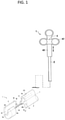
- FIG. 1 is an overall view schematically showing a guidewire holding device 1 of an endoscope according to an exemplary embodiment.
- FIG. 2 is a top view schematically showing a distal end portion of the guidewire holding device 1 of FIG. 1 .
- FIG. 3 is side view schematically showing the distal end portion of the guidewire holding device of FIG. 1 .
- an endoscope includes the guidewire holding device 1 that is a capable of holding a medical guidewire used by being inserted into the body of a patient, and disposing a treatment device (tool) in a target lumen of a hollow organ during an EUS-RV procedure.
- a treatment device tool
- the guidewire holding device 1 is configured as a combined device that combines a guidewire holder and a treatment tool into one device.
- the guidewire holding device 1 is disposed at or protruded from a distal end of an insertion portion of the endoscope.
- the guidewire holding device 1 may include a sheath 2 inserted in the insertion portion of the endoscope, an operation wire 3 inside the sheath 2, a holder 5 connected to the operation wire 3, an operation unit 4 operating the guidewire holding device 1, and a treatment device 24 contained inside the sheath 2.
- the holder 5 may advance and retract on a distal end side of the sheath 2 as the operation wire 3 advances and retracts, and as will be described later, a guidewire GW (in FIG. 6 ) positioned outside the sheath 2 can be captured and held by the holder 5.
- the sheath 2 is a flexible long member. A proximal end portion of the sheath 2 is connected to an operation portion main body 41 of the operation unit 4 which is operated by an operator.
- the sheath 2 is inserted into the body of a patient via the insertion portion of the endoscope, and has a length such that the distal end portion of the sheath 2 can protrude from the insertion portion of the endoscope.
- the sheath 2 may include a plurality of lumens as shown in FIG. 1 .
- the sheath 2 includes a lumen 21 (in FIG. 2 ) extending in a longitudinal axis L direction, and a lumen 22 extending parallel to the lumen 21.
- the lumen 21 may be configured for inserting the operation wire 3, and the lumen 22 may be configured for inserting and storing the treatment device 24.
- the sheath 2 may have an additional lumen 23 (see FIGs. 7(A) and 7(B) ) without increasing a diameter of the sheath 2.
- the lumens 21-23 may be different in size and shape from each other.
- the guidewire holding device 1 may use the lumen 21 for the treatment device 24.
- the treatment device 24 is connected to the holder 5, and functions as an operation wire or is further connected to the operation wire 3.
- the sheath 2 includes a groove 26 formed in a part of its outer periphery.
- the part of the outer periphery of the groove 26 is formed in a concave shape.
- the groove 26 is formed to extend in the longitudinal axis L direction from the distal end of the sheath 2 to the proximal end side.
- the groove 26 has the same shape as the shape of a tip edge 261 (in FIG. 4 ) from the tip to the base end of the groove 26.
- the groove 26 may be formed over the entire length of the sheath 2, or may be formed in a region having a predetermined length from the distal end to the proximal end side, for example, only in a portion protruding from the distal end of the insertion portion of the endoscope.
- the sheath 2 includes a distal end surface 27, on which a step portion 273 is formed to be recessed toward the base end side.
- the operation wire 3 is inserted in the lumen 21, and advances and retracts through the step portion 273.
- the step portion 273 has a side surface 274 formed by cutting out in a plane shape along the longitudinal axis L.
- the holder 5 is disposed at the distal end of the sheath 2.
- the holder 5 is a three-dimensional hook connected to the tip of the operation wire 3, having a substantially cylindrical outer shape.
- the hook 5 includes a slit 56 that is formed along the longitudinal axis L direction.
- the hook 5 further includes a proximal end portion 503 having a proximal end surface 505 that abuts on a distal end surface 27 of the sheath 2, and a guidewire engaging surface 53 (in FIG. 1 ) that is farther than the distal end of the groove 26.
- the guidewire GW is to be held between the guidewire engagement surface 53 and an inner wall surface 264 of the groove 26, and the hook 5 is configured to be switchable between holding the guidewire GW and releasing the guidewire GW.
- the hook 5 also includes a protrusion 58 that is formed in a region where a wire fixing portion 54 (in FIG. 3 ) is provided.
- the protrusion 58 includes a contact surface 581 that can contact a side surface of the sheath 2 when the hook 5 is retracted.
- the contact surface 581 is formed continuously from the inner wall surface of the slit 56, but the contact surface 581 may be provided separately from the slit 56.
- the protrusion 58 may be provided at a position different from the wire fixing portion 54.
- the hook 5 further include a tip portion 501 having a curved surface 502 that is formed on an outer peripheral portion of the tip portion 501.
- the hook 5 can be smoothly advanced and retracted.
- the base end portion 503 may be provided with an inclined surface 504.
- the base end portion 503 of the hook 5 may also be formed as a curved surface. Further, any shape, which is suitable for the hook 5 to be smoothly advanced and retracted, can be used to form the outer peripheral portions of the hook 5.
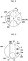
- the slit 56 is U-shaped groove. As shown in FIG. 5 , the slit 56 is opened on a first diameter line R1 on the outer peripheral surface of the hook 5 and is recessed in the radial direction. The slit 56 is formed to extend over the entire length in the longitudinal axis L direction of the hook 5. In the example shown in FIGs. 1 and 5 , a bottom surface of the slit 56 is the guidewire engagement surface 53.
- the slit 56 is opened in the direction opposite to the opening of the groove 26 of the sheath 2.
- the guidewire engagement surface 53 of the slit 56 preferably intersects with the tip edge (ridge line) 261 of the curved shape of the groove 26 to form a closed region C3.
- a bottom portion 262 of the groove 26 and the guidewire engagement surface 53 do not face each other, and the slit 56 is located on the tip side of the tip edge 261 of the groove 26.
- the guidewire engagement surface 53 is inclined so as to approach an extension line of the longitudinal axis L of the sheath 2 from the proximal end of the hook 5 toward the distal end.
- the radial position of the guidewire engagement surface 53 at the proximal end portion 503 of the hook 5 is located radially outside the position of the bottom portion 262 of the groove 26.
- the closed region C3 may be formed as a region that is closed by at least the proximal end portion of the hook 5 and the distal end edge 261 of the groove 26 when viewed in the longitudinal axis direction. Therefore, the guidewire GW captured in the closed region C3 can smoothly move back and forth in the closed region C3.
- the sheath 2 when inserting the distal end portion of the guidewire holding device 1 into the duodenum, the sheath 2 can be easily advanced along the guidewire GW.
- the groove 26 of the sheath 2 is formed on the extension of the inclination of the guidewire engagement surface 53.
- the hook 5 is a member made of resin in this exemplary embodiment.
- the hook 5 may be any material that has sufficient strength when it is formed into a small shape in consideration of insertability of the duodenal papilla.
- the hook 5 may be made of metal. Further, the hook 5 may be formed by combining metal and resin. For example, if the inner wall surface of the slit is made of resin, the guidewire GW can be slid smoothly.
- the wire fixing portion 54 into which the operation wire 3 is inserted and fixed, is provided between the slit 56 and the outer peripheral surface of the hook 5.
- the wire fixing portion 54 is provided with a U-shaped communication hole in which two lumens extending in parallel to the longitudinal axis L communicate with each other at the tip portion, and the operation wire 3 is inserted into the communication hole and fixed by, for example, an adhesive.
- the method of fixing the operation wire 3 in the wire fixing portion 54 is not limited to the adhesive.
- the operation wire 3 may be fixed in the wire fixing portion 54 by fitting, crimping, or the like.
- the operation wire 3, as shown in FIG. 1 may include first and second portions 31 and 32 that extend in the longitudinal axis L direction.
- the first wire portion 31 may extend linearly in parallel with the longitudinal axis L, and the second wire portion 32 may be bent at a plurality of places so as to be uneven in the vertical direction in side view.
- the proximal end of the first wire portion 31 is fixed to the operation slider 42 of the operation unit 4.
- the proximal end of the second wire portion 32 is arranged inside the lumen 21. That is, the base end of the second wire portion 32 is arranged inside the lumen 21 without being connected to the operation portion 4.
- the first wire portion 31 and the second wire portion 32 extend so as to overlap the longitudinal axis L in a top view.
- the first wire portion 31 and the second wire portion 32 are inserted in the lumen 21 of the sheath 2 so as to be able to move forward and backward.
- the lumen 21 has an oblong shape at least in the tip opening portion formed at the step portion 273.
- the lumen 21 is formed such that the long side 21a of the lumen 21 is parallel to the side surface 274.
- the lumen 21 and the side surface 274 of the step portion 273 function as a restriction portion, and the two operation wires 31 and 32 and the contact surface 581 serve as a restricted portion.
- the rotation around the axis is more stable than the configuration in which the operation wire 3 is regulated only by the lumen 21.
- the concave and convex shape of the second wire portion 32 is stably maintained, thereby effectively preventing the rotation of the hook 5 around the axis. That is, when a force is applied to the hook 5 in the direction of pulling the hook 5 to the proximal side, for example, when the operation slider 42 is pulled, it is difficult for an external force to be applied to the second wire portion 32, and deformation of the vertical uneven shape can be prevented.
- the guidewire engagement surface 53 of the hook 5 and the inner wall surface 264 of the groove 26 of the sheath 2 are arranged so that the guidewire GW can be held between the hook 5 and the groove 26 so as to be able to move back and forth.
- the guidewire engagement surface 53 of the slit 56 is inclined so that the distal end portion of the slit 56 is located in the vicinity of the central axis of the sheath 2, the guidewire GW is not attached to the sheath at the distal end portion 501 of the hook 5.
- the hook 5 is provided with an X-ray marker 59 that can be visually recognized in an X-ray image.
- the X-ray marker 59 is arranged in a folded-back portion of the distal end portion of the operation wire 3 and embedded in the hook 5.
- the folded-back portion of the operation wire 3 may be configured to protrude from the distal end of the hook 5.
- FIG. 7(A) shows a mode in which the hook 5 is advanced out of the sheath 2. While keeping the hook in this status, the guidewire GW can be easily caught into the slit 56 of the hook 5 and also can be positioned corresponding to the groove 26 of the sheath 2. Then, when the guidewire GW is kept inside the slit 56, the hook 5 is retracted toward the sheath 2, thereby holding the guidewire GW between the slit 56 of the hook 5 and the groove 26 of the sheath 2.
- FIG. 7(B) shows the same mode of FIG. 7(A) , but a different guidewire holding device from the one shown in FIG. 7(A) .
- the exemplary embodiment shows that the sheath 2 includes a concave portion (which is formed by the step portion 273 and the side surface 274) that can engages with a convex portion (which is formed by the contact surface 581) of hook 5.
- the invention is not limited to this configuration.
- FIG. 7(B) shows that the sheath 2 may include a flat distal end surface 27 without the concave shape of FIG.
- the hook 5 may include a flat base end face 505 without the convex contact surface 581 of FIG. 7(A) .
- the X-ray marker 59 is arranged outside the hook 5 to cover at least part of the folded-back portion of the distal end portion of the operation wire 3 and a covering tube 33 is arranged to cover at least part of the distal end of the operation wire 3 that is exposed between the sheath 2 and the hook 5.
- the lumen 22 may be used to deliver the treatment tool 24.
- the lumen 23 may be used as a liquid delivering lumen, or may be used to deliver additional treatment tool.
- the X-ray marker 59 is made of an X-ray opaque material, and serves to determine the position of the distal end of the hook 5 under X-ray fluoroscopy.
- the treatment device 24 is configured to be switchable between a first configuration or status and a second configuration or status.
- FIG. 1 shows that the treatment device 24 is in the first configuration when the treatment device 24 is contained inside the lumen 22 of the sheath 2.
- the treatment device 24 (in FIGs. 17(A) -17(E) ) is protruded from the distal end of the sheath 2, thereby switching into the second configuration. Under the second configuration, the treatment device 24 performs the intended ERCP procedure.
- the treatment device 24 may be any endoscopic treatment tool that is able to be stored inside the sheath 2 in the first configuration or be mounted on the sheath 2, and is capable of performing an ERCP procedure in the second configuration.
- the examples of the treatment device 24 will be described later based on FIGs. 17(A)-17(E) .
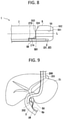
- FIGs. 9 and 10 are schematic views showing the method of inserting the guidewire holding device 1 and indwelling a treatment tool to perform an ERCP procedure.
- the guidewire GW is placed in the duodenum D.
- an endoscope insertion portion 201 of an ultrasonic endoscope 200 is inserted from the patient's mouth to the stomach St or the duodenum D.
- An access needle 202 which is inserted into the endoscope insertion portion 201 and protrudes from the tip of the endoscope insertion portion 201, is punctured into the bile duct Bd.
- the guidewire GW is inserted into the endoscope insertion portion 201, and then inserted into the bile duct Bd via a lumen of the access needle 202.
- the guidewire GW When the guidewire GW is inserted into the bile duct Bd, the guidewire GW is pushed forward so that the tip of the guidewire GW is projected from the duodenal papilla Dp and inserted into the duodenum D.
- the tip of the guidewire GW protruding from the duodenal papilla Dp extends along the lumen of the duodenum D.
- the ultrasonic endoscope 200 is removed with the guidewire GW left inside the body of a patient, and the tip of the guidewire GW is left in the duodenum D. At this time, the proximal end side of the guidewire GW is outside the body of a patient.
- the endoscope insertion portion 201 of a duodenoscope (not shown) is inserted from the patient's mouth to the duodenum D.
- the guidewire holding device 1 is inserted into the endoscope insertion portion 201, and the distal end portion of the sheath 2 is projected from the distal end of the endoscope insertion portion 201.
- the operation slider 42 is advanced to the distal end side, so that the operation wire 3 is advanced with respect to the sheath 2 thereby advancing the hook 5 to the advanced position with respect to the sheath 2.
- the sheath 2 is guided in a direction in which the hook 5 is hooked on the guidewire GW.
- the operator retracts the operation slider 42 to the proximal end side, so that the operation wire 3 is retracted with respect to the sheath 2, thereby placing the hook 5 in the retracted position.
- the guidewire GW can be brought close to the tip edge 261 of the groove 26.
- the guidewire GW is captured and held in the closed region C3 formed between the groove 26 of the sheath 2 and the slit 56 of the hook 5.
- the guidewire GW captured in the closed region C3 can smoothly move back and forth in the closed region C3.
- the distal end portion of the sheath 2 is attached to the duodenal papilla Dp along the guidewire GW while pressing the inner wall surface of the groove 26 against the guidewire GW.
- the operator pushes the operating portion 4 to insert the distal end portion of the sheath 2 into the duodenal papilla Dp as shown in FIG. 9 .
- the sheath 2 advances along the guidewire GW and reaches the inside of the bile duct Bd.
- the treatment device 24 is in a first status in which it is contained inside the sheath 2 of the guidewire holding device 1. After the insertion of the guidewire GW into the bile duct Bd is completed, the treatment device 24 is switched into a second status, in which it is protruded from the distal end of the guidewire holding device 1, which has been inserted into the duodenum along the guidewire GW. Once the treatment device 24 is protruded into the bile duct, the intended ERCP procedure is performed.
- the holding of the guidewire GW is released.
- the treatment device 24 is switched from the second status back into the first status by retracting into the guidewire holding device 1. After that, the guidewire holding device 1 is removed from the endoscope insertion portion 201.
- FIG. 11 is a flowchart showing the method for inserting the guidewire holding device 1 into the bile duct to indwell the treatment device 24 to perform the ERCP procedure according to this exemplary embodiment.
- the above described method of inserting the guidewire holding device to perform the intended treatment may be divided into the following steps.
- the bile duck is punctured by a puncturing needle.
- an access needle 202 which is inserted into the endoscope insertion portion 201 and protrudes from the tip of the endoscope insertion portion 201, is punctured into the bile duct Bd.
- the guidewire GW is inserted into the duodenum D. Specifically, the guidewire GW is inserted into the endoscope insertion portion 201, and then inserted into the bile duct Bd via the access needle 202.
- the operator pushes the guidewire GW forward so that the tip of the guidewire GW is projected from the duodenal papilla Dp and enters into the duodenum D.
- the tip of the guidewire GW protruding from the duodenal papilla Dp extends along the lumen of the duodenum D.
- an endoscope switching process is performed. Specifically, the ultrasonic endoscope 200 is removed with the guidewire GW left inside the body of a patient, and the tip of the guidewire GW is left in the duodenum D.
- the endoscope insertion portion 201 of a duodenoscope is inserted from the patient's mouth to the duodenum D.
- a guidewire catching process is performed. Specifically, the guidewire holding device 1 is inserted into the endoscope insertion portion 201, and the distal end portion of the sheath 2 is projected from the distal end of the endoscope insertion portion 201. At this time, the guidewire holding device 1, which is located at the distal end portion of the sheath 2, is guided in a direction in which the hook 5 of the guidewire holding device 1 can be easily hooked on the guidewire GW and also the guidewire GW can be easily pushed into the groove 26. As a result, the guidewire GW is captured and held within the closed region C formed by the slit 56 of the hook 5 and the groove 26. The guidewire GW can smoothly move back and forth in the closed region C.
- the guidewire GW may be inserted into the patient's body from an additional lumen of the sheath 2.
- the guidewire holding device 1 can catch the guidewire GW without pushing the guidewire GW into the groove 26 of the sheath 2.
- Step S5 a cannulation process is performed. Specifically, with the guidewire GW held between the slit 56 of the hook 5 and the groove 26, the distal end portion of the sheath 2 is attached to the duodenal papilla Dp along the guidewire GW while pressing the inner wall surface 264 of the groove 26 against the guidewire GW. The operator pushes the operating portion 4 to insert the distal end portion of the sheath 2 into the duodenal papilla Dp as shown in FIG. 10 .
- the sheath 2 advances along the guidewire GW and reaches the inside of the bile duct Bd.
- the treatment device 24 is in the first status in which it is contained inside the sheath 2 or is mounted on the sheath 2.
- the ERCP procedure is performed. Specifically, after the insertion of the guidewire GW into the bile duct Bd is completed, the treatment device 24 is switched into the second status, in which it is protruded from the guidewire holding device 1. As described above, before the ERCP is performed, the treatment device 24 is in the first status in which the treatment device 24 is contained inside the sheath 2. Once the treatment device 24 is switched into the second status in which the treatment device 24 is protruded from the guidewire holding device 1 disposed at the distal end of the sheath 2, the intended ERCP procedure is performed in the target organ.
- Step S7 after the intended ERCP procedure is completed, the holding of the guidewire GW is released.
- the treatment device 24 is retracted into the sheath 2 of the guidewire holding device 1.
- the treatment device 24 is switched from the second status into the first status.
- the guidewire holding device 1 having the treatment device 24 inside thereof is removed out to the duodenum, and the guidewire GW is removed out of the body of a patient.
- FIGs. 12-20(D) Examples of the treatment device 24 of the guidewire holding device 1 will be described below based on FIGs. 12-20(D) .
- Some of these drawings show exemplary embodiments that the sheath does not include a groove. However, even in these exemplary embodiments, the sheath may also include the groove as described above.
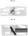
- FIG. 12 is a front view of the sheath 2 schematically showing the guidewire holding device 1 in which the treatment device 24 is contained inside the sheath 2.
- FIG. 13 is a cross-sectional view of line A-A of FIG. 12 schematically showing the first configuration of the treatment device 24.
- the treatment device 24 is a basket wire 241 for collecting the stones inside the bile duct.
- the basket wire 241 is kept inside lumen 22 of the sheath 2, and thus a basket disposed at a distal end of the basket wire 241 is not opened.
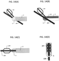
- FIG. 14(A) is a perspective side view of the guidewire holding device 1 in which the treatment device 24 is protruded from the sheath 2
- FIG. 14(B) is a cross-sectional side view of the guidewire holding device 1 in which the treatment device 24 is protruded from the sheath 2
- FIG. 14(C) is a top view of the guidewire holding device 1 in which the treatment device 24 is protruded from the sheath 2
- FIG. 14(D) is a front view of the guidewire holding device 1 in which the treatment device 24 is protruded from the sheath 2.
- the treatment device 24 is a basket wire 241.
- the basket wire 241 inside the lumen 21 is advanced in parallel with the sheath 2 in the longitudinal axis L direction.
- the basket is opened and switched into the second configuration.
- the basket wire 241 slightly changes its advancing direction when the basket wire 241 contacts with the guidewire GW.
- the basket of the basket wire 241 is moved to the target organ along with the guidewire GW.
- FIG. 15(A) a front view of the hook 5 schematically showing the second configuration of the basket wire 241 in which it is protruded from the sheath 2.
- FIG. 15(B) a front view of the sheath 2 schematically showing the same situation.
- the basket wire 241 is positioned above the guidewire GW and passes through the slit 56 of the hook 5.
- FIG. 16(A) a front view of the hook 5 schematically showing that the basket wire 241 is protruded from the sheath 2 which includes an additional lumen 23 for a second guidewire GW2.
- FIG. 16(B) a front view of the sheath 2 schematically showing the additional lumen 23.
- the additional lumen 23 communicates with the slit 56 of the hook 5. However, since the slit 56 is positioned overlapping with the additional lumen 23 in the front view of the hook 5, the additional lumen 23 is not shown in FIG. 16(A) .
- the second guidewire GW2, which is inserted into the additional lumen 23 after the first guidewire GW is released from the hook 5, will be also passed through the slit 56 as shown in FIG. 16(A) . By such a configuration, the second guidewire GW2 is able to move forward and backward to the hook 5.
- the sheath 2 may be provided with an additional lumen 23 for a second guidewire GW2.
- the second guidewire GW2 can be used to insert and indwell an additional treatment device without increase a diameter of the sheath 2.
- the first guidewire GW may be inserted into the patient's body through the additional lumen 23, and the second guidewire GW2 may be inserted into the patient's body through another different lumen without increase the diameter of the sheath 2.
- the treatment device 24 may be any treatment tool that is configured to be stored inside the sheath 2 or mounted on the sheath 2 in the first configuration before the intended treatment, and to be switched to the second configuration in which it is protruded from the guidewire holding device 1 when the intended treatment starts.
- the basket wire 241 described above is one example.
- Other examples of such a treatment tool include, but are not limited to, an electrode knife wire, diathermic dilator, ablation probe, balloon catheter, cytology brush, biopsy forceps, grasping forceps, thin endoscope, puncture needle, and the like. These examples will be described below according to FIGs. 17(A)-17(E) .
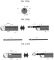
- FIG. 17(A) -17(E) show the examples of the treatment device 24 that are applicable in the exemplary embodiment.
- FIG. 17(A) is a cross-sectional view of line B-B in FIG. 17(B) schematically showing a front view of sheath 2.
- FIG. 17(B) shows two cross-sectional views of line A-A in FIG. 17(A) schematically illustrating side views of the guidewire holding device 1 when one example of the treatment device 24 is stored inside the sheath in the first configuration and then is switched into the second configuration in which the one example of the treatment device 24 is protruded from the sheath 2.
- the treatment device 24 may be an electrode knife wire.
- the left side view of FIG. 17(B) shows that the electrode knife wire is powered off when it is stored inside the sheath 2.
- the right side view of FIG. 17(B) shows that the electrode knife wire is powered on when it is protruded from the sheath 2 so that the electrode knife wire is able to perform the intended ERCP procedure.
- a diathermic dilator or an ablation probe may also be used as the treatment device 24 in this example. That is, the diathermic dilator and the ablation probe can be powered off when they are contained inside the sheath 2 in their first configuration, and be powered on when they are protruded from the sheath 2 in their second configuration.
- FIG. 17(C) shows two cross-sectional views of line A-A in FIG. 17(A) schematically illustrating side views of the guidewire holding device 1 when another example of the treatment device 24 is stored inside the sheath 2 in the first configuration and then is switched into the second configuration in which the other example of the treatment device 24 is protruded from the sheath 2.
- the treatment device 24 may be a balloon catheter.
- the left side view of FIG. 17(C) shows that the balloon catheter is stored inside the sheath 2 in the first configuration in which the balloon is not inflated.
- the right side view of FIG. 17(C) shows that the balloon is inflated when the balloon catheter is protruded from the sheath 2 so that the balloon catheter is able to perform the intended ERCP procedure.
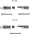
- FIG. 17(D) shows two cross-sectional views of line A-A in FIG. 17(A) schematically illustrating side views of the guidewire holding device 1 when still another example of the treatment device 24 is stored inside the sheath 2 in the first configuration and then is switched into the second configuration in which the still other example of the treatment device 24 is protruded from the sheath 2.
- the treatment device 24 may be a cytology brush.
- the left side view of FIG. 17(D) shows that the cytology brush is stored inside the sheath 2 by shrinking its brushes in its first configuration.
- the right side view of FIG. 17(D) shows that the cytology brush is protruded from the sheath 2 in its second configuration so that the cytology brush erects its brushes to perform the intended ERCP procedure.
- a biopsy forceps or a grasping forceps may also be used as the treatment device 24 in this example.
- the jaws of the biopsy forceps and the grasping forceps can be retracted when they are contained inside the sheath in their first configuration, and then opened when they are protruded from the sheath 2 in their second configuration to perform the intended ERCP procedure.
- FIG. 17(E) shows two cross-sectional views of line A-A in FIG. 17(A) schematically illustrating side views of the guidewire holding device 1 when still another example of the treatment device 24 is stored inside the sheath 2 in the first configuration and then is switched into the second configuration in which the still other example of the treatment device 24 is protruded from the sheath.
- the treatment device 24 may be a thin endoscope.
- the left side view of FIG. 17(E) shows that the thin endoscope is stored inside the sheath in its first configuration.
- the right side view of FIG. 17(E) shows that the thin endoscope is protruded from the sheath in its second configuration so that the thin endoscope can perform the intended ERCP procedure.
- a puncture needle may also be used as the treatment device in this example. That is, the puncture needle is contained inside the sheath in its first configuration, and then is protruded from the sheath in their second configuration to perform the intended ERCP procedure.
- the guidewire holding device 1 is not limited to the examples of the above-described embodiments.
- the same components as those already described will be assigned the same reference numerals and overlapping description will be omitted.
- FIG. 18(A) is a cross-sectional view of line B-B in FIG. 18(B) schematically showing a front view of sheath 2.
- FIG. 18(B) shows a cross-sectional view of line A-A in FIG. 18(A) schematically illustrating side views of a guidewire holding device 1 including a treatment device 24 that surrounds the sheath 2.
- the treatment device 24 may be a balloon 25 that is fixed to and surrounds part of the distal end of the sheath 2.
- the lumen 22 of the sheath 2 is an air delivery lumen that includes an opening inside the balloon 25.
- the balloon 25 Before the guidewire holding device 1 is inserted into the bile duct, the balloon 25 is fixed to the distal end of the sheath 2 in the first configuration in which the balloon 25 is not inflated by air delivered via the air delivery lumen. Once the guidewire holding device 1 is inserted into the bile duct along with the guidewire GW, the balloon 25 is switched into the second configuration in which the balloon 25 is inflated via the opening by air delivered via the air delivery lumen of the sheath 2, so as to perform the intended treatment.
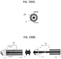
- FIG. 19(A) is a cross-sectional view of line B-B in FIG. 19(B) schematically showing a front view of sheath 2.
- FIG. 19(B) shows a cross-sectional view of line A-A in FIG. 19(A) schematically illustrating side views of the guidewire holding device 1 in which the hook 5 and the operation wire 3 serve as the treatment device 24.
- the operation wire lumen which in the previous embodiments is designated with reference numeral 21, in the second modification defines the lumen 22 into which the treatment tool 24 (i.e. the hook 5 and the operation wire 3) is inserted.
- the operation wire 3 and the hook 5 also serve as an electrode knife or a diathermic dilator wire such that the operation wire 3 is powered off in the first configuration when the hook 5 is retracted back to the sheath 2, and is powered on in the second configuration when the operation wire 3 pushes the hook 5 to advance away from the sheath 2.
- the hook 5 is made of an insulating material.
- the hook 5 is made of a conductive material.
- the distal end of the operation wire 3 may be covered by X-ray opaque material that serves to determine the position of the distal end of the treatment tool 24 or the hook 5.
- FIG. 20(A) is a cross-sectional view schematically showing a front view of the sheath 2.
- FIG. 20(B) shows a cross-sectional view of line A-A in FIG. 20(A) schematically illustrating a side view of the guidewire holding device 1 in which a basket wire 241 is connected to the operation wire 3.
- FIG. 20(C) shows a cross-sectional view of line A-A in FIG. 20(A) schematically illustrating another side view of the guidewire holding device 1 in which a basket wire 241 is connected to the operation wire 3.
- FIG. 20(D) shows a cross-sectional view of line A-A in FIG. 20(A) schematically illustrating another side view of the guidewire holding device 1 in which a basket wire 241 is connected to the operation wire 3.
- the basket wire 241 and the operation wire 3 serve as the treatment device 24.
- the basket wire 241 Inside the operation wire lumen which in the previous embodiments is designated with reference numeral 21, but here defines the lumen 22 into which the treatment tool 24 (i.e. the basket wire 241 and the operation wire 3) is inserted, the basket wire 241 has one end connected to the operation wire 3 and the other end connected to the hook 5.
- the basket wire 241 is arranged between the hook 5 and the operation wire 3.
- the basket wire 241 pushes the hook 5 so that the hook 5 advances to the advanced position to hook the guidewire GW. Once the guidewire GW is hooked on the hook 5, as shown in FIG.
- the basket wire 241 and the operation wire 3 are pulled back so that the guidewire GW is captured and held between the hook 5 and the sheath 2.
- the guidewire holding device 1 is pushed into the bile duct along with the guidewire GW as described above.
- FIG. 20(D) once the basked wire 241 protrudes from the sheath 2, it is opened so as to perform the intended ERCP procedure.
Landscapes
- Health & Medical Sciences (AREA)
- Life Sciences & Earth Sciences (AREA)
- Surgery (AREA)
- Engineering & Computer Science (AREA)
- Veterinary Medicine (AREA)
- Public Health (AREA)
- General Health & Medical Sciences (AREA)
- Animal Behavior & Ethology (AREA)
- Biomedical Technology (AREA)
- Heart & Thoracic Surgery (AREA)
- Biophysics (AREA)
- Nuclear Medicine, Radiotherapy & Molecular Imaging (AREA)
- Medical Informatics (AREA)
- Molecular Biology (AREA)
- Pathology (AREA)
- Radiology & Medical Imaging (AREA)
- Physics & Mathematics (AREA)
- Optics & Photonics (AREA)
- Pulmonology (AREA)
- Anesthesiology (AREA)
- Hematology (AREA)
- Orthopedic Medicine & Surgery (AREA)
- Vascular Medicine (AREA)
- Gastroenterology & Hepatology (AREA)
- Media Introduction/Drainage Providing Device (AREA)
- Endoscopes (AREA)
- Surgical Instruments (AREA)
Abstract
Description
- The present invention relates to a device and a method of inserting a medical treatment tool into a hollow organ of a subject (such as a patient) using a guidewire. In particular, the present invention relates to a guidewire holding device and a method of using the guidewire holding device to insert an endoscopic treatment tool into a hollow organ, such as the bile duct or the pancreatic duct, through an opening, such as the duodenal papilla.
- A method and a device of introducing a medical treatment tool into a human hollow organ using a guidewire for treatment and examination of the human hollow organ have been well known. When obstruction such as stenosis or occlusion occurs at an opening of the hollow organ, the guidewire itself cannot be inserted into the hollow organ. For example, when a duodenal papilla is tightly closed, it is difficult to insert the guidewire into a desired hollow organ such as a bile duct or a pancreatic duct via the duodenal papilla.
- As a solution in such a situation, an endoscopic ultrasound guided rendezvous technique (EUS-RV) has been developed. In a typical EUS-RV, an operator inserts an ultrasound endoscope into the digestive track via the patient's mouth. The bile duct or the pancreatic duct is confirmed through an ultrasound image, so that a puncture needle is inserted into a channel of the ultrasonic endoscope and is punctured into the bile duct or the pancreatic duct. Then, the operator inserts a first guidewire into a lumen of the puncture needle and the distal end of the first guidewire is inserted from the lumen of the puncture needle into the bile duct or the pancreatic duct. Next, the operator pushes the first guidewire to cause the distal end of the first guidewire into the duodenum from the duodenal papilla. Thereafter, the ultrasonic endoscope and the puncture needle are removed from the body of the patient, e.g., by pulling out, while the distal end of the first guidewire is indwelt in the duodenum.
- Next, the operator inserts an endoscope via the patient's mouth to the vicinity of the duodenal papilla of the duodenum. A guidewire grasping device is inserted into a channel of the endoscope so as to grasp and hold the first guidewire. While holding the first guidewire, the guidewire grasping device is pulled with respect to the endoscope, the distal end of the first guidewire is drawn into the channel of the endoscope, and is drawn out from the forceps port of the endoscope. Another catheter is inserted into the forceps port of the endoscope along the extracted first guidewire, and the tip of the catheter is inserted into the bile duct. A second guidewire is inserted into the bile duct through a lumen of the catheter.
- When the second guidewire is endoscopically indwelt, the engagement of the guidewire grasping device with the first guidewire is released. The first guidewire is removed from the patient's body, and the guidewire grasping device are removed out to duodenum, leaving the second guidewire at the bile duct. When the above operations are completed, a treatment device is indwelt via the second guidewire to perform an endoscopic retrograde cholangiopancreatography (ERCP) procedure.
- The conventional EUS-RV procedure, however, requires at least two guidewires to indwell the treatment device, and also requires to catch and release the first guidewire before performing the ERCP procedure. In order to conduct the treatment as soon as possible to reduce the burden on the patient, it has been a problem that the operation before the ERCP procedure is complicated and time-consuming.
- The invention is directed to the object to provide a guidewire holding device and an endoscope, which substantially obviate one or more of the issues due to limitations and disadvantages of related EUS-RV devices.
- In order to address this object, a guidewire holding device according to
claim 1, a guidewire holding device according to claim 14 and an endoscope according to claim 15 are provided. - A first guidewire holding device according to the invention comprises a sheath including a lumen, a holder disposed at a distal end of the sheath and configured to be switchable between holding a guidewire and releasing the guidewire, a treatment tool inserted in the lumen to perform an intended treatment, and a wire connected to the treatment tool and configured to move the treatment tool between a first configuration and a second configuration. In the first configuration, the treatment tool is contained inside the lumen, and, in the second configuration, the treatment tool is protruded from the distal end of the sheath.
- Preferred embodiments of the first guidewire holding device may include one or more of the following features individually or combined.
- The holder may be disposed in front of the treatment tool. Alternatively or additionally, the holder may be connected to the treatment tool.
- The holder may include a slit. The slit may be configured to have both the guidewire and the treatment tool pass therethrough with the treatment tool moving along and above the guidewire.
- The slit may have a width equal to or larger than a diameter of the lumen. Alternatively or additionally, the slit may have depth equal to or larger than a sum of a diameter of the guidewire and a diameter of the guidewire.
- A central axis of the slit preferably substantially coincides with a center of the lumen.
- The treatment tool may be connected to the holder. The wire, which is connected to the treatment tool, may be powered on when the treatment tool is protruded from the sheath.
- The treatment tool may comprises a basket connected between the holder and the wire. The basket may be defined by a basket wire and may be used for collecting stones inside the bile duct. Preferably, the basket is closed when it is inside the sheath, and opened when it is protruded from the sheath.
- The holder may be disposed in front of the basket. Alternatively or additionally, the holder may be connected to the basket. Alternatively or additionally, the holder may include a slit which preferably is configured to have both the guidewire and the basket pass therethrough with the basket moving along and above the guidewire.
- Beside the lumen, the guidewire holding device may comprise a first additional lumen. An operation wire may be inserted in the first additional lumen. The holder may be connected to the operation wire. Further, the holder may be configured to be advanced from and retracted to the sheath by operating the operation wire.
- The sheath may include a second additional lumen. Basically, the sheath may include only a first additional lumen or only a second additional lumen. The sheath may, however, also include a first additional lumen and a second additional lumen.
- The second additional lumen may be configured to allow insertion of a further guidewire. Alternatively or additionally, the second additional lumen may be configured to communicate with the slit of the holder.
- The slit may be configured to have both the further guidewire and the treatment tool pass therethrough with the treatment tool moving along and above the further guidewire. Alternatively or additionally, the slit may have a width equal to or larger than a diameter of the second additional lumen.
- A second guidewire holding device according to the invention comprises a sheath including a lumen and a first additional lumen; a holder disposed at a distal end of the sheath and configured to be switchable between holding a guidewire and releasing the guidewire; an operation wire inserted in the first additional lumen and connected to the holder; a treatment tool mounted on the sheath and connected to the lumen and operable to be switchable between a first configuration and a second configuration, wherein the treatment tool comprises a balloon and the lumen is designed in the form of an air delivering lumen. In the first configuration, the balloon is not inflated. In the second configuration, the balloon is inserted into a target organ and is inflated by air delivered via the lumen.
- Preferred embodiments of the second guidewire holding device may include one or more of the features described above with reference to the first guidewire holding device individually or combined.
- The guidewire holding device may be used to insert a treatment tool into the body of a patient. A guidewire may be indwelled at a bile duct and a duodenum through a duodenal papilla, the treatment tool may be inserted through a sheath of an endoscope into the duodenum, a holder may be used to connect the treatment tool to the guidewire in the duodenum, the treatment tool may be inserted into the bile duct along with the guidewire at a first status, the treatment tool may be switched from the first status into a second status, and a treatment may be performed after the switching of the treatment tool to the second status. In the first status, the treatment tool may be contained inside the sheath; in the second status, the treatment tool may be protruded from a distal end of the sheath.
- An endoscope according to the invention comprises an operation unit, an insertion portion extending from the operation unit; and a first or second guidewire holding device as described above which is protruded from a distal end of the insertion portion.
- Additional features and advantages will be set forth in the description that follows, and in part will be apparent from the description, or may be learned by practice of the invention. The objectives and other advantages of the disclosed input device will be realized and attained by the structure particularly pointed out in the written description and claims thereof as well as the appended drawings.
- The following detailed description of preferred embodiments can be read in connection with the accompanying drawings in which like numerals designate like elements and in which:
-
FIG. 1 is an exploded view schematically showing a guidewire holding device of an endoscope according to an exemplary embodiment. -
FIG. 2 is a top view schematically showing a distal end portion of the guidewire holding device ofFIG. 1 . -
FIG. 3 is a side view schematically showing the distal end portion of the guidewire holding device ofFIG. 1 . -
FIG. 4 is a front view of the sheath of an exemplary embodiment. -
FIG. 5 is a sectional view taken along the line V-V inFIG. 3 . -
FIG. 6 is a schematic diagram showing, in partial transparent view, a mode of using the guidewire holding device according to an exemplary embodiment. -
FIG. 7(A) is a schematic diagram showing, in partial transparent view, another mode of using the guidewire holding device according to an exemplary embodiment, andFIG. 7(B) is a perspective view showing the same mode of using a different guidewire holding device according to another exemplary embodiment. -
FIG. 8 is a top view showing a modified example of the guidewire holding device according to the exemplary embodiment. -
FIG. 9 is a diagram illustrating a method of introducing the guidewire holding device into a hollow organ according to an exemplary embodiment. -
FIG. 10 is a diagram illustrating a method of showing an example of performing a procedure by a rendezvous method using the guidewire holding device according to the exemplary embodiment. -
FIG. 11 is a flowchart illustrating general steps of a method of introducing the guidewire holding device into a hollow organ according to an exemplary embodiment. -
FIG. 12 is a front view of a sheath schematically showing a guidewire holding device including a treatment device contained inside the sheath. -
FIG. 13 is a cross-sectional view of line A-A ofFIG. 12 schematically showing the treatment device in a first configuration in which the treatment is contained inside the sheath. -
FIG. 14(A) is a perspective side view of a guidewire holding device in which a treatment device is protruded from a sheath according to an exemplary embodiment;FIG. 14(B) is a cross-sectional side view of the guidewire holding device in which the treatment device is protruded from the sheath according to an exemplary embodiment;FIG. 14(C) is a top view of the guidewire holding device in which the treatment device is protruded from the sheath according to an exemplary embodiment; and ;FIG. 14(D) is a front view of the guidewire holding device in which the treatment device is protruded from the sheath according to an exemplary embodiment. -
FIG. 15(A) is a front view of a holder schematically showing a treatment device in a second configuration in which it is protruded from asheath 2, andFIG. 15(B) a front view of a sheath schematically showing the treatment device in the second configuration. -
FIG. 16(A) a front view of a holder schematically showing that a treatment device is protruded from a sheath, andFIG. 16(B) a front view of a sheath schematically showing that the treatment device is protruded from the sheath. -
FIG. 17(A) -17(E) show the examples of a treatment device in first and second status/configurations according to the exemplary embodiment. -
FIG. 18(A) is a cross-sectional view of line B-B inFIG. 18(B) schematically showing a front view of sheath, andFIG. 18(B) shows a cross-sectional view of line A-A inFIG. 18(A) schematically illustrating side views of a guidewire holding device according to another exemplary embodiment. -
FIG. 19(A) is a cross-sectional view of line B-B inFIG. 19(B) schematically showing a front view of a sheath, andFIG. 19(B) shows a cross-sectional view of line A-A inFIG. 19(A) schematically illustrating side views of a guidewire holding device according to another exemplary embodiment. -
FIG. 20(A) is a cross-sectional view schematically showing a front view of a sheath,FIG. 20(B) shows a cross-sectional view of line A-A inFIG. 20(A) schematically illustrating a side view of a guidewire holding device,FIG. 20(C) shows a cross-sectional view of line A-A inFIG. 20(A) schematically illustrating another side view of the guidewire holding device,FIG. 20(D) shows a cross-sectional view of line A-A inFIG. 20(A) schematically illustrating still another side view of the guidewire holding device according to another exemplary embodiment. - Various examples of a device and a method for inserting a medical treatment tool into a hollow organ of a subject (such as a patient) using a guidewire will be described with reference to the drawings.
-
FIG. 1 is an overall view schematically showing aguidewire holding device 1 of an endoscope according to an exemplary embodiment.FIG. 2 is a top view schematically showing a distal end portion of theguidewire holding device 1 ofFIG. 1 .FIG. 3 is side view schematically showing the distal end portion of the guidewire holding device ofFIG. 1 . - As shown in
FIG. 1 , an endoscope includes theguidewire holding device 1 that is a capable of holding a medical guidewire used by being inserted into the body of a patient, and disposing a treatment device (tool) in a target lumen of a hollow organ during an EUS-RV procedure. - In this exemplary embodiment, the
guidewire holding device 1 is configured as a combined device that combines a guidewire holder and a treatment tool into one device. Theguidewire holding device 1 is disposed at or protruded from a distal end of an insertion portion of the endoscope. - As shown in
FIGs. 1-4 , theguidewire holding device 1 may include asheath 2 inserted in the insertion portion of the endoscope, anoperation wire 3 inside thesheath 2, aholder 5 connected to theoperation wire 3, an operation unit 4 operating theguidewire holding device 1, and atreatment device 24 contained inside thesheath 2. - In the
guidewire holding device 1, theholder 5 may advance and retract on a distal end side of thesheath 2 as theoperation wire 3 advances and retracts, and as will be described later, a guidewire GW (inFIG. 6 ) positioned outside thesheath 2 can be captured and held by theholder 5. - The
sheath 2 is a flexible long member. A proximal end portion of thesheath 2 is connected to an operation portionmain body 41 of the operation unit 4 which is operated by an operator. Thesheath 2 is inserted into the body of a patient via the insertion portion of the endoscope, and has a length such that the distal end portion of thesheath 2 can protrude from the insertion portion of the endoscope. Thesheath 2 may include a plurality of lumens as shown inFIG. 1 . In this exemplary embodiment, thesheath 2 includes a lumen 21 (inFIG. 2 ) extending in a longitudinal axis L direction, and alumen 22 extending parallel to thelumen 21. Thelumen 21 may be configured for inserting theoperation wire 3, and thelumen 22 may be configured for inserting and storing thetreatment device 24. Thesheath 2 may have an additional lumen 23 (seeFIGs. 7(A) and 7(B) ) without increasing a diameter of thesheath 2. The lumens 21-23 may be different in size and shape from each other. - As will be described later, the
guidewire holding device 1 may use thelumen 21 for thetreatment device 24. In that situation, thetreatment device 24 is connected to theholder 5, and functions as an operation wire or is further connected to theoperation wire 3. - The
sheath 2 includes agroove 26 formed in a part of its outer periphery. The part of the outer periphery of thegroove 26 is formed in a concave shape. Thegroove 26 is formed to extend in the longitudinal axis L direction from the distal end of thesheath 2 to the proximal end side. Thegroove 26 has the same shape as the shape of a tip edge 261 (inFIG. 4 ) from the tip to the base end of thegroove 26. Thegroove 26 may be formed over the entire length of thesheath 2, or may be formed in a region having a predetermined length from the distal end to the proximal end side, for example, only in a portion protruding from the distal end of the insertion portion of the endoscope. - As shown in
FIG. 2 , thesheath 2 includes adistal end surface 27, on which astep portion 273 is formed to be recessed toward the base end side. Theoperation wire 3 is inserted in thelumen 21, and advances and retracts through thestep portion 273. Thestep portion 273 has aside surface 274 formed by cutting out in a plane shape along the longitudinal axis L. When the base end of theprotrusion 58 is in contact with thestep portion 273, a slight gap is preferably formed between thebase end face 505 of the holder 5 (excluding the protrusion 58) and the distal end face 27 of thesheath 2. When theholder 5 and thesheath 2 are in contact with each other as described above, the guidewire GW (inFIG. 6 ) is held between theguidewire engagement surface 53 and theinner wall surface 264 of thegroove 26. - As shown in
FIG. 1 , theholder 5 is disposed at the distal end of thesheath 2. In this exemplary embodiment, theholder 5 is a three-dimensional hook connected to the tip of theoperation wire 3, having a substantially cylindrical outer shape. Thehook 5 includes aslit 56 that is formed along the longitudinal axis L direction. As shown inFIG. 2 , thehook 5 further includes aproximal end portion 503 having aproximal end surface 505 that abuts on adistal end surface 27 of thesheath 2, and a guidewire engaging surface 53 (inFIG. 1 ) that is farther than the distal end of thegroove 26. As will be described later, the guidewire GW is to be held between theguidewire engagement surface 53 and aninner wall surface 264 of thegroove 26, and thehook 5 is configured to be switchable between holding the guidewire GW and releasing the guidewire GW. - Further referring to
FIG. 1 , thehook 5 also includes aprotrusion 58 that is formed in a region where a wire fixing portion 54 (inFIG. 3 ) is provided. Theprotrusion 58 includes acontact surface 581 that can contact a side surface of thesheath 2 when thehook 5 is retracted. Thecontact surface 581 is formed continuously from the inner wall surface of theslit 56, but thecontact surface 581 may be provided separately from theslit 56. Theprotrusion 58 may be provided at a position different from thewire fixing portion 54. - As shown in
FIG. 2 , thehook 5 further include atip portion 501 having acurved surface 502 that is formed on an outer peripheral portion of thetip portion 501. Thus, thehook 5 can be smoothly advanced and retracted. In addition, as shownFIG. 8 , besides that thetip end portion 501 of the hook is provided with thecurved surface 502, thebase end portion 503 may be provided with aninclined surface 504. Thebase end portion 503 of thehook 5 may also be formed as a curved surface. Further, any shape, which is suitable for thehook 5 to be smoothly advanced and retracted, can be used to form the outer peripheral portions of thehook 5. - The
slit 56 is U-shaped groove. As shown inFIG. 5 , theslit 56 is opened on a first diameter line R1 on the outer peripheral surface of thehook 5 and is recessed in the radial direction. Theslit 56 is formed to extend over the entire length in the longitudinal axis L direction of thehook 5. In the example shown inFIGs. 1 and5 , a bottom surface of theslit 56 is theguidewire engagement surface 53. - Referring to
FIGs. 5 and6 , theslit 56 is opened in the direction opposite to the opening of thegroove 26 of thesheath 2. When viewed from the longitudinal axis direction (when viewed from the front along the longitudinal axis), theguidewire engagement surface 53 of theslit 56 preferably intersects with the tip edge (ridge line) 261 of the curved shape of thegroove 26 to form a closed region C3. On the other hand, as shown inFIG. 3 , in the direction of the longitudinal axis L, abottom portion 262 of thegroove 26 and theguidewire engagement surface 53 do not face each other, and theslit 56 is located on the tip side of thetip edge 261 of thegroove 26. - As shown in
FIGs. 3 and6 , theguidewire engagement surface 53 is inclined so as to approach an extension line of the longitudinal axis L of thesheath 2 from the proximal end of thehook 5 toward the distal end. As shown inFIG. 5 , the radial position of theguidewire engagement surface 53 at theproximal end portion 503 of thehook 5 is located radially outside the position of thebottom portion 262 of thegroove 26. The closed region C3 may be formed as a region that is closed by at least the proximal end portion of thehook 5 and thedistal end edge 261 of thegroove 26 when viewed in the longitudinal axis direction. Therefore, the guidewire GW captured in the closed region C3 can smoothly move back and forth in the closed region C3. As a result, when inserting the distal end portion of theguidewire holding device 1 into the duodenum, thesheath 2 can be easily advanced along the guidewire GW. Thegroove 26 of thesheath 2 is formed on the extension of the inclination of theguidewire engagement surface 53. - The
hook 5 is a member made of resin in this exemplary embodiment. Thehook 5 may be any material that has sufficient strength when it is formed into a small shape in consideration of insertability of the duodenal papilla. Thehook 5 may be made of metal. Further, thehook 5 may be formed by combining metal and resin. For example, if the inner wall surface of the slit is made of resin, the guidewire GW can be slid smoothly. - As shown in
FIG. 3 , thewire fixing portion 54, into which theoperation wire 3 is inserted and fixed, is provided between theslit 56 and the outer peripheral surface of thehook 5. Thewire fixing portion 54 is provided with a U-shaped communication hole in which two lumens extending in parallel to the longitudinal axis L communicate with each other at the tip portion, and theoperation wire 3 is inserted into the communication hole and fixed by, for example, an adhesive. The method of fixing theoperation wire 3 in thewire fixing portion 54 is not limited to the adhesive. Theoperation wire 3 may be fixed in thewire fixing portion 54 by fitting, crimping, or the like. - The
operation wire 3, as shown inFIG. 1 , may include first andsecond portions first wire portion 31 may extend linearly in parallel with the longitudinal axis L, and thesecond wire portion 32 may be bent at a plurality of places so as to be uneven in the vertical direction in side view. The proximal end of thefirst wire portion 31 is fixed to theoperation slider 42 of the operation unit 4. The proximal end of thesecond wire portion 32 is arranged inside thelumen 21. That is, the base end of thesecond wire portion 32 is arranged inside thelumen 21 without being connected to the operation portion 4. As shown inFIG. 2 , thefirst wire portion 31 and thesecond wire portion 32 extend so as to overlap the longitudinal axis L in a top view. Thefirst wire portion 31 and thesecond wire portion 32 are inserted in thelumen 21 of thesheath 2 so as to be able to move forward and backward. As shown inFIG. 4 , thelumen 21 has an oblong shape at least in the tip opening portion formed at thestep portion 273. Thelumen 21 is formed such that thelong side 21a of thelumen 21 is parallel to theside surface 274. With this configuration, thelumen 21 and theside surface 274 of thestep portion 273 function as a restriction portion, and the twooperation wires contact surface 581 serve as a restricted portion. As a result, the rotation around the axis is more stable than the configuration in which theoperation wire 3 is regulated only by thelumen 21. Also, as thesecond wire portion 32 moves in the vertical direction, the concave and convex shape of thesecond wire portion 32 is stably maintained, thereby effectively preventing the rotation of thehook 5 around the axis. That is, when a force is applied to thehook 5 in the direction of pulling thehook 5 to the proximal side, for example, when theoperation slider 42 is pulled, it is difficult for an external force to be applied to thesecond wire portion 32, and deformation of the vertical uneven shape can be prevented. - The
guidewire engagement surface 53 of thehook 5 and theinner wall surface 264 of thegroove 26 of thesheath 2 are arranged so that the guidewire GW can be held between thehook 5 and thegroove 26 so as to be able to move back and forth. - As shown in
FIG. 6 , since theguidewire engagement surface 53 of theslit 56 is inclined so that the distal end portion of theslit 56 is located in the vicinity of the central axis of thesheath 2, the guidewire GW is not attached to the sheath at thedistal end portion 501 of thehook 5. As a result, when inserting the distal end portion of theguidewire holding device 1 into the duodenum, thesheath 2 can be easily advanced along the guidewire GW. Also, as inFIG. 6 , thehook 5 is provided with anX-ray marker 59 that can be visually recognized in an X-ray image. In this exemplary embodiment, theX-ray marker 59 is arranged in a folded-back portion of the distal end portion of theoperation wire 3 and embedded in thehook 5. The folded-back portion of theoperation wire 3 may be configured to protrude from the distal end of thehook 5. -
FIG. 7(A) shows a mode in which thehook 5 is advanced out of thesheath 2. While keeping the hook in this status, the guidewire GW can be easily caught into theslit 56 of thehook 5 and also can be positioned corresponding to thegroove 26 of thesheath 2. Then, when the guidewire GW is kept inside theslit 56, thehook 5 is retracted toward thesheath 2, thereby holding the guidewire GW between theslit 56 of thehook 5 and thegroove 26 of thesheath 2. -
FIG. 7(B) shows the same mode ofFIG. 7(A) , but a different guidewire holding device from the one shown inFIG. 7(A) . As shown inFIGs. 1 through FIG. 7(A) , the exemplary embodiment shows that thesheath 2 includes a concave portion (which is formed by thestep portion 273 and the side surface 274) that can engages with a convex portion (which is formed by the contact surface 581) ofhook 5. However, the invention is not limited to this configuration. As an example,FIG. 7(B) shows that thesheath 2 may include a flatdistal end surface 27 without the concave shape ofFIG. 7(A) , and thehook 5 may include a flatbase end face 505 without theconvex contact surface 581 ofFIG. 7(A) . Also, as shown inFIG. 7(B) , theX-ray marker 59 is arranged outside thehook 5 to cover at least part of the folded-back portion of the distal end portion of theoperation wire 3 and a coveringtube 33 is arranged to cover at least part of the distal end of theoperation wire 3 that is exposed between thesheath 2 and thehook 5. By this configuration ofFIG. 7(B) , when thehook 5 is retracted to thesheath 2, the coveringtube 33 and theX-ray marker 59 are accommodated inside thelumen 21 of thesheath 2. Thelumen 22 may be used to deliver thetreatment tool 24. Thelumen 23 may be used as a liquid delivering lumen, or may be used to deliver additional treatment tool. - The
X-ray marker 59 is made of an X-ray opaque material, and serves to determine the position of the distal end of thehook 5 under X-ray fluoroscopy. - In this exemplary embodiment, during an EUS-RV procedure, the
treatment device 24 is configured to be switchable between a first configuration or status and a second configuration or status.FIG. 1 shows that thetreatment device 24 is in the first configuration when thetreatment device 24 is contained inside thelumen 22 of thesheath 2. After theguidewire holding device 1 is inserted into the bile duct along the guidewire GW, the treatment device 24 (inFIGs. 17(A) -17(E) ) is protruded from the distal end of thesheath 2, thereby switching into the second configuration. Under the second configuration, thetreatment device 24 performs the intended ERCP procedure. - The
treatment device 24 may be any endoscopic treatment tool that is able to be stored inside thesheath 2 in the first configuration or be mounted on thesheath 2, and is capable of performing an ERCP procedure in the second configuration. The examples of thetreatment device 24 will be described later based onFIGs. 17(A)-17(E) . - Next, a method of introducing the
guidewire holding device 1 into the luminal organ, for example, the bile duct by the rendezvous method will be described as an example.FIGs. 9 and10 are schematic views showing the method of inserting theguidewire holding device 1 and indwelling a treatment tool to perform an ERCP procedure. - First, the guidewire GW is placed in the duodenum D. Specifically, as shown in
FIG. 9 , anendoscope insertion portion 201 of anultrasonic endoscope 200 is inserted from the patient's mouth to the stomach St or the duodenum D.An access needle 202, which is inserted into theendoscope insertion portion 201 and protrudes from the tip of theendoscope insertion portion 201, is punctured into the bile duct Bd. After that, the guidewire GW is inserted into theendoscope insertion portion 201, and then inserted into the bile duct Bd via a lumen of theaccess needle 202. When the guidewire GW is inserted into the bile duct Bd, the guidewire GW is pushed forward so that the tip of the guidewire GW is projected from the duodenal papilla Dp and inserted into the duodenum D. By advancing the guidewire GW toward the duodenal papilla Dp, the tip of the guidewire GW protruding from the duodenal papilla Dp extends along the lumen of the duodenum D. - Then, the
ultrasonic endoscope 200 is removed with the guidewire GW left inside the body of a patient, and the tip of the guidewire GW is left in the duodenum D. At this time, the proximal end side of the guidewire GW is outside the body of a patient. - Next, as shown in
FIG. 10 , theendoscope insertion portion 201 of a duodenoscope (not shown) is inserted from the patient's mouth to the duodenum D. Then, theguidewire holding device 1 is inserted into theendoscope insertion portion 201, and the distal end portion of thesheath 2 is projected from the distal end of theendoscope insertion portion 201. Then, theoperation slider 42 is advanced to the distal end side, so that theoperation wire 3 is advanced with respect to thesheath 2 thereby advancing thehook 5 to the advanced position with respect to thesheath 2. Thesheath 2 is guided in a direction in which thehook 5 is hooked on the guidewire GW. - Next, the operator retracts the
operation slider 42 to the proximal end side, so that theoperation wire 3 is retracted with respect to thesheath 2, thereby placing thehook 5 in the retracted position. By retracting thehook 5 to the retracted position, the guidewire GW can be brought close to thetip edge 261 of thegroove 26. In the retracted position, as described above, the guidewire GW is captured and held in the closed region C3 formed between thegroove 26 of thesheath 2 and theslit 56 of thehook 5. The guidewire GW captured in the closed region C3 can smoothly move back and forth in the closed region C3. - Next, with the guidewire GW held in the closed region C3 between the
slit 56 and thegroove 26, the distal end portion of thesheath 2 is attached to the duodenal papilla Dp along the guidewire GW while pressing the inner wall surface of thegroove 26 against the guidewire GW. The operator pushes the operating portion 4 to insert the distal end portion of thesheath 2 into the duodenal papilla Dp as shown inFIG. 9 . As the guidewire GW has already passed through the bile duct Bd and extended to the duodenum D via the duodenal papilla Dp, when theguidewire holding device 1 is pushed in, thesheath 2 advances along the guidewire GW and reaches the inside of the bile duct Bd. - At this time, the
treatment device 24 is in a first status in which it is contained inside thesheath 2 of theguidewire holding device 1. After the insertion of the guidewire GW into the bile duct Bd is completed, thetreatment device 24 is switched into a second status, in which it is protruded from the distal end of theguidewire holding device 1, which has been inserted into the duodenum along the guidewire GW. Once thetreatment device 24 is protruded into the bile duct, the intended ERCP procedure is performed. - After the intended ERCP procedure is completed, the holding of the guidewire GW is released. The
treatment device 24 is switched from the second status back into the first status by retracting into theguidewire holding device 1. After that, theguidewire holding device 1 is removed from theendoscope insertion portion 201. -
FIG. 11 is a flowchart showing the method for inserting theguidewire holding device 1 into the bile duct to indwell thetreatment device 24 to perform the ERCP procedure according to this exemplary embodiment. - As shown in
FIG. 11 , the above described method of inserting the guidewire holding device to perform the intended treatment may be divided into the following steps. - At Step S1, the bile duck is punctured by a puncturing needle. Specifically, an
access needle 202, which is inserted into theendoscope insertion portion 201 and protrudes from the tip of theendoscope insertion portion 201, is punctured into the bile duct Bd. - At Step S2, the guidewire GW is inserted into the duodenum D. Specifically, the guidewire GW is inserted into the
endoscope insertion portion 201, and then inserted into the bile duct Bd via theaccess needle 202. When the guidewire GW is inserted into the bile duct Bd, the operator pushes the guidewire GW forward so that the tip of the guidewire GW is projected from the duodenal papilla Dp and enters into the duodenum D. By advancing the guidewire GW toward the duodenal papilla Dp, the tip of the guidewire GW protruding from the duodenal papilla Dp extends along the lumen of the duodenum D. - At Step S3, an endoscope switching process is performed. Specifically, the
ultrasonic endoscope 200 is removed with the guidewire GW left inside the body of a patient, and the tip of the guidewire GW is left in the duodenum D. Theendoscope insertion portion 201 of a duodenoscope is inserted from the patient's mouth to the duodenum D. - At Step S4, a guidewire catching process is performed. Specifically, the
guidewire holding device 1 is inserted into theendoscope insertion portion 201, and the distal end portion of thesheath 2 is projected from the distal end of theendoscope insertion portion 201. At this time, theguidewire holding device 1, which is located at the distal end portion of thesheath 2, is guided in a direction in which thehook 5 of theguidewire holding device 1 can be easily hooked on the guidewire GW and also the guidewire GW can be easily pushed into thegroove 26. As a result, the guidewire GW is captured and held within the closed region C formed by theslit 56 of thehook 5 and thegroove 26. The guidewire GW can smoothly move back and forth in the closed region C. Alternatively, at Step S4, the guidewire GW may be inserted into the patient's body from an additional lumen of thesheath 2. In this situation, theguidewire holding device 1 can catch the guidewire GW without pushing the guidewire GW into thegroove 26 of thesheath 2. - At Step S5, a cannulation process is performed. Specifically, with the guidewire GW held between the
slit 56 of thehook 5 and thegroove 26, the distal end portion of thesheath 2 is attached to the duodenal papilla Dp along the guidewire GW while pressing theinner wall surface 264 of thegroove 26 against the guidewire GW. The operator pushes the operating portion 4 to insert the distal end portion of thesheath 2 into the duodenal papilla Dp as shown inFIG. 10 . As the guidewire GW has already passed through the bile duct Bd and extended to the duodenum D via the duodenal papilla Dp, when theguidewire holding device 1 is pushed in, thesheath 2 advances along the guidewire GW and reaches the inside of the bile duct Bd. At this time, thetreatment device 24 is in the first status in which it is contained inside thesheath 2 or is mounted on thesheath 2. - At Step S6, the ERCP procedure is performed. Specifically, after the insertion of the guidewire GW into the bile duct Bd is completed, the
treatment device 24 is switched into the second status, in which it is protruded from theguidewire holding device 1. As described above, before the ERCP is performed, thetreatment device 24 is in the first status in which thetreatment device 24 is contained inside thesheath 2. Once thetreatment device 24 is switched into the second status in which thetreatment device 24 is protruded from theguidewire holding device 1 disposed at the distal end of thesheath 2, the intended ERCP procedure is performed in the target organ. - At Step S7, after the intended ERCP procedure is completed, the holding of the guidewire GW is released. The
treatment device 24 is retracted into thesheath 2 of theguidewire holding device 1. Thus, thetreatment device 24 is switched from the second status into the first status. Then, theguidewire holding device 1 having thetreatment device 24 inside thereof is removed out to the duodenum, and the guidewire GW is removed out of the body of a patient. - Examples of the
treatment device 24 of theguidewire holding device 1 will be described below based onFIGs. 12-20(D) . Some of these drawings show exemplary embodiments that the sheath does not include a groove. However, even in these exemplary embodiments, the sheath may also include the groove as described above. -
FIG. 12 is a front view of thesheath 2 schematically showing theguidewire holding device 1 in which thetreatment device 24 is contained inside thesheath 2.FIG. 13 is a cross-sectional view of line A-A ofFIG. 12 schematically showing the first configuration of thetreatment device 24. - As shown in
FIGs. 12 and 13 , in this exemplary embodiment, thetreatment device 24 is abasket wire 241 for collecting the stones inside the bile duct. In the first configuration, thebasket wire 241 is kept insidelumen 22 of thesheath 2, and thus a basket disposed at a distal end of thebasket wire 241 is not opened. -
FIG. 14(A) is a perspective side view of theguidewire holding device 1 in which thetreatment device 24 is protruded from thesheath 2,FIG. 14(B) is a cross-sectional side view of theguidewire holding device 1 in which thetreatment device 24 is protruded from thesheath 2,FIG. 14(C) is a top view of theguidewire holding device 1 in which thetreatment device 24 is protruded from thesheath 2, andFIG. 14(D) is a front view of theguidewire holding device 1 in which thetreatment device 24 is protruded from thesheath 2. As shown inFIGs. 14(A)-14(D) , thetreatment device 24 is abasket wire 241. Thebasket wire 241 inside thelumen 21 is advanced in parallel with thesheath 2 in the longitudinal axis L direction. When the basket of thebasket wire 241 is protrude out of thesheath 2, the basket is opened and switched into the second configuration. Also thebasket wire 241 slightly changes its advancing direction when thebasket wire 241 contacts with the guidewire GW. The basket of thebasket wire 241 is moved to the target organ along with the guidewire GW. -
FIG. 15(A) a front view of thehook 5 schematically showing the second configuration of thebasket wire 241 in which it is protruded from thesheath 2.FIG. 15(B) a front view of thesheath 2 schematically showing the same situation. As shown inFIG. 15(A) , thebasket wire 241 is positioned above the guidewire GW and passes through theslit 56 of thehook 5. -
FIG. 16(A) a front view of thehook 5 schematically showing that thebasket wire 241 is protruded from thesheath 2 which includes anadditional lumen 23 for a second guidewire GW2.FIG. 16(B) a front view of thesheath 2 schematically showing theadditional lumen 23. Theadditional lumen 23 communicates with theslit 56 of thehook 5. However, since theslit 56 is positioned overlapping with theadditional lumen 23 in the front view of thehook 5, theadditional lumen 23 is not shown inFIG. 16(A) . The second guidewire GW2, which is inserted into theadditional lumen 23 after the first guidewire GW is released from thehook 5, will be also passed through theslit 56 as shown inFIG. 16(A) . By such a configuration, the second guidewire GW2 is able to move forward and backward to thehook 5. - As shown in
FIG. 16(B) , thesheath 2 may be provided with anadditional lumen 23 for a second guidewire GW2. The second guidewire GW2 can be used to insert and indwell an additional treatment device without increase a diameter of thesheath 2. Alternatively, as described at paragraph [0087], the first guidewire GW may be inserted into the patient's body through theadditional lumen 23, and the second guidewire GW2 may be inserted into the patient's body through another different lumen without increase the diameter of thesheath 2. - The
treatment device 24 may be any treatment tool that is configured to be stored inside thesheath 2 or mounted on thesheath 2 in the first configuration before the intended treatment, and to be switched to the second configuration in which it is protruded from theguidewire holding device 1 when the intended treatment starts. Thebasket wire 241 described above is one example. Other examples of such a treatment tool include, but are not limited to, an electrode knife wire, diathermic dilator, ablation probe, balloon catheter, cytology brush, biopsy forceps, grasping forceps, thin endoscope, puncture needle, and the like. These examples will be described below according toFIGs. 17(A)-17(E) . -
FIG. 17(A) -17(E) show the examples of thetreatment device 24 that are applicable in the exemplary embodiment.FIG. 17(A) is a cross-sectional view of line B-B inFIG. 17(B) schematically showing a front view ofsheath 2.FIG. 17(B) shows two cross-sectional views of line A-A inFIG. 17(A) schematically illustrating side views of theguidewire holding device 1 when one example of thetreatment device 24 is stored inside the sheath in the first configuration and then is switched into the second configuration in which the one example of thetreatment device 24 is protruded from thesheath 2. - In this example, the
treatment device 24 may be an electrode knife wire. The left side view ofFIG. 17(B) shows that the electrode knife wire is powered off when it is stored inside thesheath 2. The right side view ofFIG. 17(B) shows that the electrode knife wire is powered on when it is protruded from thesheath 2 so that the electrode knife wire is able to perform the intended ERCP procedure. Also, as shown in 17(B), instead of the electrode knife wire, a diathermic dilator or an ablation probe may also be used as thetreatment device 24 in this example. That is, the diathermic dilator and the ablation probe can be powered off when they are contained inside thesheath 2 in their first configuration, and be powered on when they are protruded from thesheath 2 in their second configuration. -
FIG. 17(C) shows two cross-sectional views of line A-A inFIG. 17(A) schematically illustrating side views of theguidewire holding device 1 when another example of thetreatment device 24 is stored inside thesheath 2 in the first configuration and then is switched into the second configuration in which the other example of thetreatment device 24 is protruded from thesheath 2. - In this example, the
treatment device 24 may be a balloon catheter. The left side view ofFIG. 17(C) shows that the balloon catheter is stored inside thesheath 2 in the first configuration in which the balloon is not inflated. The right side view ofFIG. 17(C) shows that the balloon is inflated when the balloon catheter is protruded from thesheath 2 so that the balloon catheter is able to perform the intended ERCP procedure. -
FIG. 17(D) shows two cross-sectional views of line A-A inFIG. 17(A) schematically illustrating side views of theguidewire holding device 1 when still another example of thetreatment device 24 is stored inside thesheath 2 in the first configuration and then is switched into the second configuration in which the still other example of thetreatment device 24 is protruded from thesheath 2. - In this example, the
treatment device 24 may be a cytology brush. The left side view ofFIG. 17(D) shows that the cytology brush is stored inside thesheath 2 by shrinking its brushes in its first configuration. The right side view ofFIG. 17(D) shows that the cytology brush is protruded from thesheath 2 in its second configuration so that the cytology brush erects its brushes to perform the intended ERCP procedure. Also, as shown in 17(D), instead of the cytology brush, a biopsy forceps or a grasping forceps may also be used as thetreatment device 24 in this example. That is, the jaws of the biopsy forceps and the grasping forceps can be retracted when they are contained inside the sheath in their first configuration, and then opened when they are protruded from thesheath 2 in their second configuration to perform the intended ERCP procedure. -
FIG. 17(E) shows two cross-sectional views of line A-A inFIG. 17(A) schematically illustrating side views of theguidewire holding device 1 when still another example of thetreatment device 24 is stored inside thesheath 2 in the first configuration and then is switched into the second configuration in which the still other example of thetreatment device 24 is protruded from the sheath. - In this example, the
treatment device 24 may be a thin endoscope. The left side view ofFIG. 17(E) shows that the thin endoscope is stored inside the sheath in its first configuration. The right side view ofFIG. 17(E) shows that the thin endoscope is protruded from the sheath in its second configuration so that the thin endoscope can perform the intended ERCP procedure. Also, as shown in 17(E), instead of the thin endoscope, a puncture needle may also be used as the treatment device in this example. That is, the puncture needle is contained inside the sheath in its first configuration, and then is protruded from the sheath in their second configuration to perform the intended ERCP procedure. - The
guidewire holding device 1 according to the present invention is not limited to the examples of the above-described embodiments. In the following description, the same components as those already described will be assigned the same reference numerals and overlapping description will be omitted. -
FIG. 18(A) is a cross-sectional view of line B-B inFIG. 18(B) schematically showing a front view ofsheath 2.FIG. 18(B) shows a cross-sectional view of line A-A inFIG. 18(A) schematically illustrating side views of aguidewire holding device 1 including atreatment device 24 that surrounds thesheath 2. In this modified embodiment, thetreatment device 24 may be aballoon 25 that is fixed to and surrounds part of the distal end of thesheath 2. Thelumen 22 of thesheath 2 is an air delivery lumen that includes an opening inside theballoon 25. Before theguidewire holding device 1 is inserted into the bile duct, theballoon 25 is fixed to the distal end of thesheath 2 in the first configuration in which theballoon 25 is not inflated by air delivered via the air delivery lumen. Once theguidewire holding device 1 is inserted into the bile duct along with the guidewire GW, theballoon 25 is switched into the second configuration in which theballoon 25 is inflated via the opening by air delivered via the air delivery lumen of thesheath 2, so as to perform the intended treatment. -
FIG. 19(A) is a cross-sectional view of line B-B inFIG. 19(B) schematically showing a front view ofsheath 2.FIG. 19(B) shows a cross-sectional view of line A-A inFIG. 19(A) schematically illustrating side views of theguidewire holding device 1 in which thehook 5 and theoperation wire 3 serve as thetreatment device 24. The operation wire lumen which in the previous embodiments is designated withreference numeral 21, in the second modification defines thelumen 22 into which the treatment tool 24 (i.e. thehook 5 and the operation wire 3) is inserted. In this modified embodiment, theoperation wire 3 and thehook 5 also serve as an electrode knife or a diathermic dilator wire such that theoperation wire 3 is powered off in the first configuration when thehook 5 is retracted back to thesheath 2, and is powered on in the second configuration when theoperation wire 3 pushes thehook 5 to advance away from thesheath 2. In the situation of using the electrode knife, thehook 5 is made of an insulating material. In the situation of using the diathermic dilator wire, thehook 5 is made of a conductive material. Also, the distal end of theoperation wire 3 may be covered by X-ray opaque material that serves to determine the position of the distal end of thetreatment tool 24 or thehook 5. -
FIG. 20(A) is a cross-sectional view schematically showing a front view of thesheath 2.FIG. 20(B) shows a cross-sectional view of line A-A inFIG. 20(A) schematically illustrating a side view of theguidewire holding device 1 in which abasket wire 241 is connected to theoperation wire 3.FIG. 20(C) shows a cross-sectional view of line A-A inFIG. 20(A) schematically illustrating another side view of theguidewire holding device 1 in which abasket wire 241 is connected to theoperation wire 3.FIG. 20(D) shows a cross-sectional view of line A-A inFIG. 20(A) schematically illustrating another side view of theguidewire holding device 1 in which abasket wire 241 is connected to theoperation wire 3. - In this exemplary embodiment, the
basket wire 241 and theoperation wire 3 serve as thetreatment device 24. Inside the operation wire lumen which in the previous embodiments is designated withreference numeral 21, but here defines thelumen 22 into which the treatment tool 24 (i.e. thebasket wire 241 and the operation wire 3) is inserted, thebasket wire 241 has one end connected to theoperation wire 3 and the other end connected to thehook 5. Thus, as shown inFIG. 20(B) , thebasket wire 241 is arranged between thehook 5 and theoperation wire 3. Thebasket wire 241 pushes thehook 5 so that thehook 5 advances to the advanced position to hook the guidewire GW. Once the guidewire GW is hooked on thehook 5, as shown inFIG. 20(C) , thebasket wire 241 and theoperation wire 3 are pulled back so that the guidewire GW is captured and held between thehook 5 and thesheath 2. Theguidewire holding device 1 is pushed into the bile duct along with the guidewire GW as described above. As shown inFIG. 20(D) , once the baskedwire 241 protrudes from thesheath 2, it is opened so as to perform the intended ERCP procedure. - Although the present invention has been described in connection with the above exemplary embodiments, it will be appreciated by those skilled in the art that additions, deletions, modifications, and substitutions not specifically described may be made without department from the invention as defined in the appended claims.
Claims (15)
- A guidewire holding device (1) comprising:a sheath (2) including a lumen (22) ;a holder (5) disposed at a distal end of the sheath (2) and configured to be switchable between holding a guidewire (GW) and releasing the guidewire (GW);a treatment tool (24) inserted in the lumen (22) to perform an intended treatment; anda wire connected to the treatment tool (24) and configured to move the treatment tool (24) between a first configuration and a second configuration,wherein, in the first configuration, the treatment tool (24) is contained inside the lumen (22), andwherein, in the second configuration, the treatment tool (24) is protruded from the distal end of the sheath (2).
- The guidewire holding device according to claim 1, wherein the holder (5) is disposed in front of the treatment tool (24), and/or
wherein the holder (5) is connected to the treatment tool (24). - The guidewire holding device according to claim 1 or 2, wherein the holder (5) includes a slit (56),
the slit (56) in particular being configured to have both the guidewire (GW) and the treatment tool (24) pass therethrough with the treatment tool (24) moving along and above the guidewire (GW). - The guidewire holding device according to claim 3, wherein the slit (56) has a width equal to or larger than a diameter of the lumen (22).
- The guidewire holding device according to claim 3 or 4,
wherein the slit (56) has a depth equal to or larger than a sum of a diameter of the guidewire (GW) and a diameter of the guidewire (GW). - The guidewire holding device according to any of claims 3 to 5, wherein a central axis of the slit (56) substantially coincides with a center of the lumen (22).
- The guidewire holding device according to any one of claims 1 to 6, wherein the treatment tool (24) is connected to the holder (5), and/or
wherein the wire, which is connected to the treatment tool (24), is powered on when the treatment tool (24) is protruded from the sheath (2). - The guidewire holding device according to any one of claims 1 to 7, wherein the treatment tool (24) comprises a basket connected between the holder (5) and the wire (3),
the basket in particular being closed when it is inside the sheath (2), and opened when it is protruded from the sheath (2). - The guidewire holding device according to claim 8,wherein the holder (5) is disposed in front of the basket, and/orwherein the holder (5) is connected to the basket, and/orwherein the holder (5) includes a slit (56),the slit (56) in particular being configured to have both the guidewire (GW) and the basket pass therethrough with the basket moving along and above the guidewire (GW).
- The guidewire holding device according to any one of claims 1 to 9, further comprising a first additional lumen (21), and an operation wire (3) inserted in the first additional lumen (21),
the holder (5) in particular being connected to the operation wire (3) and/or being configured to be advanced from and retracted to the sheath (2) by operating the operation wire (3). - The guidewire holding device according to any one of claims 1 to 10, wherein the sheath (2) includes a second additional lumen (23).
- The guidewire holding device according to claim 11, wherein the second additional lumen (23) is configured to allow insertion of a further guidewire (GW2) and/or to communicate with the slit (56) of the holder (5).
- The guidewire holding device according to claim 12,wherein the slit (56) is configured to have both the further guidewire (GW2) and the treatment tool (24) pass therethrough with the treatment tool (24) moving along and above the further guidewire (GW2), and/orwherein the slit (56) has a width equal to or larger than a diameter of the second additional lumen (23).
- A guidewire holding device comprising:a sheath (2) including a lumen (22) and a first additional lumen (21);a holder (5) disposed at a distal end of the sheath (2) and configured to be switchable between holding a guidewire (GW) and releasing the guidewire (GW);an operation wire (3) inserted in the first additional lumen (21) and connected to the holder (5);a treatment tool (24) mounted on the sheath (2) and connected to the lumen (22) and operable to be switchable between a first configuration and a second configuration,wherein the treatment tool (24) comprises a balloon (25) and the lumen (22) is designed in the form of an air delivering lumen,wherein, in the first configuration, the balloon (25) is not inflated, andwherein, in the second configuration, the balloon (25) is inserted into a target organ and is inflated by air delivered via the lumen (22).
- An endoscope comprising:an operation unit,an insertion portion extending from the operation unit; anda guidewire holding device according to any one of claims 1 to 14, which is protruded from a distal end of the insertion portion.
Applications Claiming Priority (1)
| Application Number | Priority Date | Filing Date | Title |
|---|---|---|---|
| US202063080089P | 2020-09-18 | 2020-09-18 |
Publications (2)
| Publication Number | Publication Date |
|---|---|
| EP3970777A1 true EP3970777A1 (en) | 2022-03-23 |
| EP3970777B1 EP3970777B1 (en) | 2025-11-19 |
Family
ID=77774726
Family Applications (1)
| Application Number | Title | Priority Date | Filing Date |
|---|---|---|---|
| EP21196744.3A Active EP3970777B1 (en) | 2020-09-18 | 2021-09-15 | Device of inserting treatment device into hollow organ |
Country Status (3)
| Country | Link |
|---|---|
| US (2) | US12053195B2 (en) |
| EP (1) | EP3970777B1 (en) |
| CN (1) | CN114190865B (en) |
Citations (4)
| Publication number | Priority date | Publication date | Assignee | Title |
|---|---|---|---|---|
| US20020095141A1 (en) * | 2001-01-16 | 2002-07-18 | Scimed Life Systems, Inc. | Rapid exchange sheath for deployment of medical devices and methods of use |
| US20030040769A1 (en) * | 2001-08-23 | 2003-02-27 | Kelley Gregory S. | Single lumen rapid-exchange catheter |
| US20050075647A1 (en) * | 2000-03-10 | 2005-04-07 | Greg Walters | Tool for facilitating the connecting of a catheter or other tubular member onto a guide-wire without access to the ends of the guide-wire |
| US20160121084A1 (en) * | 2014-10-29 | 2016-05-05 | Olympus Corporation | Method for inserting endoscopic device into hollow organ using guide wire |
Family Cites Families (21)
| Publication number | Priority date | Publication date | Assignee | Title |
|---|---|---|---|---|
| DE10192161T1 (en) * | 2000-05-30 | 2002-09-05 | Olympus Optical Co | Medical guidewire |
| JP4488280B2 (en) * | 2002-06-07 | 2010-06-23 | オリンパス株式会社 | Endoscopic treatment tool and endoscope apparatus |
| JP2004249093A (en) * | 2003-01-31 | 2004-09-09 | Olympus Corp | Basket forceps |
| US8197505B2 (en) * | 2005-10-14 | 2012-06-12 | Endocross Ltd. | Balloon catheter system for treating vascular occlusions |
| JP5718077B2 (en) * | 2011-02-03 | 2015-05-13 | オリンパス株式会社 | Endoscope |
| US9757103B2 (en) * | 2014-10-29 | 2017-09-12 | Olympus Corporation | Method for inserting endoscopic device into hollow organ |
| WO2016103900A1 (en) * | 2014-12-25 | 2016-06-30 | オリンパス株式会社 | Medical instrument and medical system |
| EP3275495A4 (en) * | 2015-03-25 | 2018-12-05 | Olympus Corporation | Treatment instrument |
| US10016123B2 (en) * | 2015-07-14 | 2018-07-10 | Olympus Corporation | Method of inserting treatment tool |
| CN109069175B (en) * | 2016-04-21 | 2021-09-03 | 奥林巴斯株式会社 | Treatment tool for endoscope |
| EP3593699A1 (en) * | 2017-03-10 | 2020-01-15 | Olympus Corporation | Guide wire gripping unit |
| WO2018229925A1 (en) * | 2017-06-15 | 2018-12-20 | オリンパス株式会社 | Catheter |
| US10881831B2 (en) * | 2017-07-19 | 2021-01-05 | Hoya Corporation | Endoscopic basket delivery catheter |
| US10898681B2 (en) * | 2017-07-19 | 2021-01-26 | Hoya Corporation | Endoscopic cannulating devices and methods of use |
| EP3720535B1 (en) * | 2017-12-04 | 2023-01-04 | Children's National Medical Center | Soft cylindrical torque tool for medical devices with lumen |
| JP7001827B2 (en) * | 2018-07-20 | 2022-01-20 | オリンパス株式会社 | Guide wire holder |
| US20200315657A1 (en) * | 2019-04-08 | 2020-10-08 | Daniel E. Matthews | Adductor Canal Block Introducer |
| WO2021061963A1 (en) * | 2019-09-24 | 2021-04-01 | Boston Scientific Scimed, Inc. | Wedge-lock sheath retention mechanism |
| WO2021127585A1 (en) * | 2019-12-20 | 2021-06-24 | Emory University | Guide-wire torque device |
| EP4117765A2 (en) * | 2020-03-13 | 2023-01-18 | Bard Access Systems, Inc. | Guidewire-management devices and methods thereof |
| MX2022011209A (en) * | 2020-03-13 | 2022-10-07 | Bard Access Systems Inc | Guidewire-management devices and methods thereof. |
-
2021
- 2021-09-14 US US17/474,448 patent/US12053195B2/en active Active
- 2021-09-15 EP EP21196744.3A patent/EP3970777B1/en active Active
- 2021-09-17 CN CN202111091332.1A patent/CN114190865B/en active Active
-
2024
- 2024-06-27 US US18/755,964 patent/US20240350155A1/en active Pending
Patent Citations (4)
| Publication number | Priority date | Publication date | Assignee | Title |
|---|---|---|---|---|
| US20050075647A1 (en) * | 2000-03-10 | 2005-04-07 | Greg Walters | Tool for facilitating the connecting of a catheter or other tubular member onto a guide-wire without access to the ends of the guide-wire |
| US20020095141A1 (en) * | 2001-01-16 | 2002-07-18 | Scimed Life Systems, Inc. | Rapid exchange sheath for deployment of medical devices and methods of use |
| US20030040769A1 (en) * | 2001-08-23 | 2003-02-27 | Kelley Gregory S. | Single lumen rapid-exchange catheter |
| US20160121084A1 (en) * | 2014-10-29 | 2016-05-05 | Olympus Corporation | Method for inserting endoscopic device into hollow organ using guide wire |
Also Published As
| Publication number | Publication date |
|---|---|
| EP3970777B1 (en) | 2025-11-19 |
| CN114190865A (en) | 2022-03-18 |
| US12053195B2 (en) | 2024-08-06 |
| CN114190865B (en) | 2025-10-17 |
| US20220087695A1 (en) | 2022-03-24 |
| US20240350155A1 (en) | 2024-10-24 |
Similar Documents
| Publication | Publication Date | Title |
|---|---|---|
| JP5161235B2 (en) | Biopsy collection instrument | |
| US20190290355A1 (en) | Radio frequency ablation coil | |
| JP2001340468A (en) | Medical guidewire | |
| JP2010508084A5 (en) | ||
| US20250114576A1 (en) | Guide wire holder | |
| JP7162727B2 (en) | Double-lumen end caps used in quarry baskets and quarry baskets | |
| WO2006033309A1 (en) | Treatment means introduction member, stent delivery catheter, and pipeline system | |
| CN110381896B (en) | Support transfer device | |
| US11701498B2 (en) | Guide wire gripping unit | |
| US9468743B2 (en) | Catheter for positioning a wire guide | |
| JP2001340288A (en) | Medical guidewire | |
| EP3970777B1 (en) | Device of inserting treatment device into hollow organ | |
| JP4695428B2 (en) | Endoscopic treatment tool | |
| EP1841489B1 (en) | Resheathing tool | |
| JP2022133795A (en) | catheter | |
| JPH11318820A (en) | Endoscope catheter | |
| Schutz et al. | A new device to simplify endoscopic plastic stent insertion | |
| WO2019202764A1 (en) | Treatment tool | |
| HK1225661B (en) | Transjugular intrahepatic portosystemic shunt device | |
| HK1106734B (en) | Resheathing tool |
Legal Events
| Date | Code | Title | Description |
|---|---|---|---|
| PUAI | Public reference made under article 153(3) epc to a published international application that has entered the european phase |
Free format text: ORIGINAL CODE: 0009012 |
|
| STAA | Information on the status of an ep patent application or granted ep patent |
Free format text: STATUS: REQUEST FOR EXAMINATION WAS MADE |
|
| 17P | Request for examination filed |
Effective date: 20210915 |
|
| AK | Designated contracting states |
Kind code of ref document: A1 Designated state(s): AL AT BE BG CH CY CZ DE DK EE ES FI FR GB GR HR HU IE IS IT LI LT LU LV MC MK MT NL NO PL PT RO RS SE SI SK SM TR |
|
| P01 | Opt-out of the competence of the unified patent court (upc) registered |
Effective date: 20230526 |
|
| STAA | Information on the status of an ep patent application or granted ep patent |
Free format text: STATUS: EXAMINATION IS IN PROGRESS |
|
| 17Q | First examination report despatched |
Effective date: 20230802 |
|
| REG | Reference to a national code |
Ref country code: DE Ref legal event code: R079 Free format text: PREVIOUS MAIN CLASS: A61M0025010000 Ipc: A61B0001010000 Ref document number: 602021042543 Country of ref document: DE |
|
| GRAP | Despatch of communication of intention to grant a patent |
Free format text: ORIGINAL CODE: EPIDOSNIGR1 |
|
| STAA | Information on the status of an ep patent application or granted ep patent |
Free format text: STATUS: GRANT OF PATENT IS INTENDED |
|
| RIC1 | Information provided on ipc code assigned before grant |
Ipc: A61B 8/12 20060101ALI20250603BHEP Ipc: A61B 6/12 20060101ALI20250603BHEP Ipc: A61B 1/273 20060101ALI20250603BHEP Ipc: A61B 1/018 20060101ALI20250603BHEP Ipc: A61M 25/10 20130101ALI20250603BHEP Ipc: A61M 25/09 20060101ALI20250603BHEP Ipc: A61M 25/01 20060101ALI20250603BHEP Ipc: A61B 1/01 20060101AFI20250603BHEP |
|
| INTG | Intention to grant announced |
Effective date: 20250618 |
|
| GRAS | Grant fee paid |
Free format text: ORIGINAL CODE: EPIDOSNIGR3 |
|
| GRAA | (expected) grant |
Free format text: ORIGINAL CODE: 0009210 |
|
| STAA | Information on the status of an ep patent application or granted ep patent |
Free format text: STATUS: THE PATENT HAS BEEN GRANTED |
|
| AK | Designated contracting states |
Kind code of ref document: B1 Designated state(s): AL AT BE BG CH CY CZ DE DK EE ES FI FR GB GR HR HU IE IS IT LI LT LU LV MC MK MT NL NO PL PT RO RS SE SI SK SM TR |
|
| REG | Reference to a national code |
Ref country code: CH Ref legal event code: F10 Free format text: ST27 STATUS EVENT CODE: U-0-0-F10-F00 (AS PROVIDED BY THE NATIONAL OFFICE) Effective date: 20251119 Ref country code: GB Ref legal event code: FG4D |
|
| REG | Reference to a national code |
Ref country code: DE Ref legal event code: R096 Ref document number: 602021042543 Country of ref document: DE |
|
| REG | Reference to a national code |
Ref country code: IE Ref legal event code: FG4D |
|
| REG | Reference to a national code |
Ref country code: NL Ref legal event code: MP Effective date: 20251119 |
|
| PG25 | Lapsed in a contracting state [announced via postgrant information from national office to epo] |
Ref country code: ES Free format text: LAPSE BECAUSE OF FAILURE TO SUBMIT A TRANSLATION OF THE DESCRIPTION OR TO PAY THE FEE WITHIN THE PRESCRIBED TIME-LIMIT Effective date: 20251119 |
|
| REG | Reference to a national code |
Ref country code: LT Ref legal event code: MG9D |
|
| PG25 | Lapsed in a contracting state [announced via postgrant information from national office to epo] |
Ref country code: NO Free format text: LAPSE BECAUSE OF FAILURE TO SUBMIT A TRANSLATION OF THE DESCRIPTION OR TO PAY THE FEE WITHIN THE PRESCRIBED TIME-LIMIT Effective date: 20260219 |
|
| PG25 | Lapsed in a contracting state [announced via postgrant information from national office to epo] |
Ref country code: AT Free format text: LAPSE BECAUSE OF FAILURE TO SUBMIT A TRANSLATION OF THE DESCRIPTION OR TO PAY THE FEE WITHIN THE PRESCRIBED TIME-LIMIT Effective date: 20251119 Ref country code: HR Free format text: LAPSE BECAUSE OF FAILURE TO SUBMIT A TRANSLATION OF THE DESCRIPTION OR TO PAY THE FEE WITHIN THE PRESCRIBED TIME-LIMIT Effective date: 20251119 Ref country code: FI Free format text: LAPSE BECAUSE OF FAILURE TO SUBMIT A TRANSLATION OF THE DESCRIPTION OR TO PAY THE FEE WITHIN THE PRESCRIBED TIME-LIMIT Effective date: 20251119 |
|
| REG | Reference to a national code |
Ref country code: AT Ref legal event code: MK05 Ref document number: 1858079 Country of ref document: AT Kind code of ref document: T Effective date: 20251119 |
|
| PG25 | Lapsed in a contracting state [announced via postgrant information from national office to epo] |
Ref country code: NL Free format text: LAPSE BECAUSE OF FAILURE TO SUBMIT A TRANSLATION OF THE DESCRIPTION OR TO PAY THE FEE WITHIN THE PRESCRIBED TIME-LIMIT Effective date: 20251119 |
|
| PG25 | Lapsed in a contracting state [announced via postgrant information from national office to epo] |
Ref country code: RS Free format text: LAPSE BECAUSE OF FAILURE TO SUBMIT A TRANSLATION OF THE DESCRIPTION OR TO PAY THE FEE WITHIN THE PRESCRIBED TIME-LIMIT Effective date: 20260219 |
|
| PG25 | Lapsed in a contracting state [announced via postgrant information from national office to epo] |
Ref country code: IS Free format text: LAPSE BECAUSE OF FAILURE TO SUBMIT A TRANSLATION OF THE DESCRIPTION OR TO PAY THE FEE WITHIN THE PRESCRIBED TIME-LIMIT Effective date: 20260319 |
|
| PG25 | Lapsed in a contracting state [announced via postgrant information from national office to epo] |
Ref country code: PT Free format text: LAPSE BECAUSE OF FAILURE TO SUBMIT A TRANSLATION OF THE DESCRIPTION OR TO PAY THE FEE WITHIN THE PRESCRIBED TIME-LIMIT Effective date: 20260319 |
|
| PG25 | Lapsed in a contracting state [announced via postgrant information from national office to epo] |
Ref country code: PL Free format text: LAPSE BECAUSE OF FAILURE TO SUBMIT A TRANSLATION OF THE DESCRIPTION OR TO PAY THE FEE WITHIN THE PRESCRIBED TIME-LIMIT Effective date: 20251119 |
|
| PG25 | Lapsed in a contracting state [announced via postgrant information from national office to epo] |
Ref country code: LV Free format text: LAPSE BECAUSE OF FAILURE TO SUBMIT A TRANSLATION OF THE DESCRIPTION OR TO PAY THE FEE WITHIN THE PRESCRIBED TIME-LIMIT Effective date: 20251119 |
|
| PG25 | Lapsed in a contracting state [announced via postgrant information from national office to epo] |
Ref country code: BG Free format text: LAPSE BECAUSE OF FAILURE TO SUBMIT A TRANSLATION OF THE DESCRIPTION OR TO PAY THE FEE WITHIN THE PRESCRIBED TIME-LIMIT Effective date: 20251119 |
|
| PG25 | Lapsed in a contracting state [announced via postgrant information from national office to epo] |
Ref country code: LT Free format text: LAPSE BECAUSE OF FAILURE TO SUBMIT A TRANSLATION OF THE DESCRIPTION OR TO PAY THE FEE WITHIN THE PRESCRIBED TIME-LIMIT Effective date: 20251119 |
|
| PG25 | Lapsed in a contracting state [announced via postgrant information from national office to epo] |
Ref country code: SM Free format text: LAPSE BECAUSE OF FAILURE TO SUBMIT A TRANSLATION OF THE DESCRIPTION OR TO PAY THE FEE WITHIN THE PRESCRIBED TIME-LIMIT Effective date: 20251119 |
|
| PG25 | Lapsed in a contracting state [announced via postgrant information from national office to epo] |
Ref country code: DK Free format text: LAPSE BECAUSE OF FAILURE TO SUBMIT A TRANSLATION OF THE DESCRIPTION OR TO PAY THE FEE WITHIN THE PRESCRIBED TIME-LIMIT Effective date: 20251119 |
|
| PG25 | Lapsed in a contracting state [announced via postgrant information from national office to epo] |
Ref country code: IT Free format text: LAPSE BECAUSE OF FAILURE TO SUBMIT A TRANSLATION OF THE DESCRIPTION OR TO PAY THE FEE WITHIN THE PRESCRIBED TIME-LIMIT Effective date: 20251119 |
|
| PG25 | Lapsed in a contracting state [announced via postgrant information from national office to epo] |
Ref country code: EE Free format text: LAPSE BECAUSE OF FAILURE TO SUBMIT A TRANSLATION OF THE DESCRIPTION OR TO PAY THE FEE WITHIN THE PRESCRIBED TIME-LIMIT Effective date: 20251119 |
|
| PG25 | Lapsed in a contracting state [announced via postgrant information from national office to epo] |
Ref country code: CZ Free format text: LAPSE BECAUSE OF FAILURE TO SUBMIT A TRANSLATION OF THE DESCRIPTION OR TO PAY THE FEE WITHIN THE PRESCRIBED TIME-LIMIT Effective date: 20251119 |
|
| PG25 | Lapsed in a contracting state [announced via postgrant information from national office to epo] |
Ref country code: SK Free format text: LAPSE BECAUSE OF FAILURE TO SUBMIT A TRANSLATION OF THE DESCRIPTION OR TO PAY THE FEE WITHIN THE PRESCRIBED TIME-LIMIT Effective date: 20251119 |
|
| PG25 | Lapsed in a contracting state [announced via postgrant information from national office to epo] |
Ref country code: SE Free format text: LAPSE BECAUSE OF FAILURE TO SUBMIT A TRANSLATION OF THE DESCRIPTION OR TO PAY THE FEE WITHIN THE PRESCRIBED TIME-LIMIT Effective date: 20251119 |