EP3970645A1 - Implant, insertion device and plate assembly - Google Patents
Implant, insertion device and plate assembly Download PDFInfo
- Publication number
- EP3970645A1 EP3970645A1 EP20197497.9A EP20197497A EP3970645A1 EP 3970645 A1 EP3970645 A1 EP 3970645A1 EP 20197497 A EP20197497 A EP 20197497A EP 3970645 A1 EP3970645 A1 EP 3970645A1
- Authority
- EP
- European Patent Office
- Prior art keywords
- implant
- insertion device
- holding
- engagement portion
- engagement
- Prior art date
- Legal status (The legal status is an assumption and is not a legal conclusion. Google has not performed a legal analysis and makes no representation as to the accuracy of the status listed.)
- Granted
Links
Images










Classifications
-
- A—HUMAN NECESSITIES
- A61—MEDICAL OR VETERINARY SCIENCE; HYGIENE
- A61F—FILTERS IMPLANTABLE INTO BLOOD VESSELS; PROSTHESES; DEVICES PROVIDING PATENCY TO, OR PREVENTING COLLAPSING OF, TUBULAR STRUCTURES OF THE BODY, e.g. STENTS; ORTHOPAEDIC, NURSING OR CONTRACEPTIVE DEVICES; FOMENTATION; TREATMENT OR PROTECTION OF EYES OR EARS; BANDAGES, DRESSINGS OR ABSORBENT PADS; FIRST-AID KITS
- A61F2/00—Filters implantable into blood vessels; Prostheses, i.e. artificial substitutes or replacements for parts of the body; Appliances for connecting them with the body; Devices providing patency to, or preventing collapsing of, tubular structures of the body, e.g. stents
- A61F2/02—Prostheses implantable into the body
- A61F2/30—Joints
- A61F2/44—Joints for the spine, e.g. vertebrae or spinal discs
-
- A—HUMAN NECESSITIES
- A61—MEDICAL OR VETERINARY SCIENCE; HYGIENE
- A61B—DIAGNOSIS; SURGERY; IDENTIFICATION
- A61B17/00—Surgical instruments, devices or methods
- A61B17/56—Surgical instruments or methods for treatment of bones or joints; Devices specially adapted therefor
- A61B17/58—Surgical instruments or methods for treatment of bones or joints; Devices specially adapted therefor for osteosynthesis, e.g. bone plates, screws or setting implements
- A61B17/68—Internal fixation devices, including fasteners and spinal fixators, even if a part thereof projects from the skin
- A61B17/80—Cortical plates, i.e. bone plates; Instruments for holding or positioning cortical plates, or for compressing bones attached to cortical plates
- A61B17/8033—Cortical plates, i.e. bone plates; Instruments for holding or positioning cortical plates, or for compressing bones attached to cortical plates having indirect contact with screw heads, or having contact with screw heads maintained with the aid of additional components, e.g. nuts, wedges or head covers
- A61B17/8042—Cortical plates, i.e. bone plates; Instruments for holding or positioning cortical plates, or for compressing bones attached to cortical plates having indirect contact with screw heads, or having contact with screw heads maintained with the aid of additional components, e.g. nuts, wedges or head covers the additional component being a cover over the screw head
-
- A—HUMAN NECESSITIES
- A61—MEDICAL OR VETERINARY SCIENCE; HYGIENE
- A61B—DIAGNOSIS; SURGERY; IDENTIFICATION
- A61B17/00—Surgical instruments, devices or methods
- A61B17/56—Surgical instruments or methods for treatment of bones or joints; Devices specially adapted therefor
- A61B17/58—Surgical instruments or methods for treatment of bones or joints; Devices specially adapted therefor for osteosynthesis, e.g. bone plates, screws or setting implements
- A61B17/68—Internal fixation devices, including fasteners and spinal fixators, even if a part thereof projects from the skin
- A61B17/70—Spinal positioners or stabilisers, e.g. stabilisers comprising fluid filler in an implant
- A61B17/7059—Cortical plates
-
- A—HUMAN NECESSITIES
- A61—MEDICAL OR VETERINARY SCIENCE; HYGIENE
- A61F—FILTERS IMPLANTABLE INTO BLOOD VESSELS; PROSTHESES; DEVICES PROVIDING PATENCY TO, OR PREVENTING COLLAPSING OF, TUBULAR STRUCTURES OF THE BODY, e.g. STENTS; ORTHOPAEDIC, NURSING OR CONTRACEPTIVE DEVICES; FOMENTATION; TREATMENT OR PROTECTION OF EYES OR EARS; BANDAGES, DRESSINGS OR ABSORBENT PADS; FIRST-AID KITS
- A61F2/00—Filters implantable into blood vessels; Prostheses, i.e. artificial substitutes or replacements for parts of the body; Appliances for connecting them with the body; Devices providing patency to, or preventing collapsing of, tubular structures of the body, e.g. stents
- A61F2/02—Prostheses implantable into the body
- A61F2/30—Joints
- A61F2/30721—Accessories
- A61F2/30749—Fixation appliances for connecting prostheses to the body
-
- A—HUMAN NECESSITIES
- A61—MEDICAL OR VETERINARY SCIENCE; HYGIENE
- A61F—FILTERS IMPLANTABLE INTO BLOOD VESSELS; PROSTHESES; DEVICES PROVIDING PATENCY TO, OR PREVENTING COLLAPSING OF, TUBULAR STRUCTURES OF THE BODY, e.g. STENTS; ORTHOPAEDIC, NURSING OR CONTRACEPTIVE DEVICES; FOMENTATION; TREATMENT OR PROTECTION OF EYES OR EARS; BANDAGES, DRESSINGS OR ABSORBENT PADS; FIRST-AID KITS
- A61F2/00—Filters implantable into blood vessels; Prostheses, i.e. artificial substitutes or replacements for parts of the body; Appliances for connecting them with the body; Devices providing patency to, or preventing collapsing of, tubular structures of the body, e.g. stents
- A61F2/02—Prostheses implantable into the body
- A61F2/30—Joints
- A61F2/44—Joints for the spine, e.g. vertebrae or spinal discs
- A61F2/442—Intervertebral or spinal discs, e.g. resilient
-
- A—HUMAN NECESSITIES
- A61—MEDICAL OR VETERINARY SCIENCE; HYGIENE
- A61F—FILTERS IMPLANTABLE INTO BLOOD VESSELS; PROSTHESES; DEVICES PROVIDING PATENCY TO, OR PREVENTING COLLAPSING OF, TUBULAR STRUCTURES OF THE BODY, e.g. STENTS; ORTHOPAEDIC, NURSING OR CONTRACEPTIVE DEVICES; FOMENTATION; TREATMENT OR PROTECTION OF EYES OR EARS; BANDAGES, DRESSINGS OR ABSORBENT PADS; FIRST-AID KITS
- A61F2/00—Filters implantable into blood vessels; Prostheses, i.e. artificial substitutes or replacements for parts of the body; Appliances for connecting them with the body; Devices providing patency to, or preventing collapsing of, tubular structures of the body, e.g. stents
- A61F2/02—Prostheses implantable into the body
- A61F2/30—Joints
- A61F2/44—Joints for the spine, e.g. vertebrae or spinal discs
- A61F2/4455—Joints for the spine, e.g. vertebrae or spinal discs for the fusion of spinal bodies, e.g. intervertebral fusion of adjacent spinal bodies, e.g. fusion cages
-
- A—HUMAN NECESSITIES
- A61—MEDICAL OR VETERINARY SCIENCE; HYGIENE
- A61F—FILTERS IMPLANTABLE INTO BLOOD VESSELS; PROSTHESES; DEVICES PROVIDING PATENCY TO, OR PREVENTING COLLAPSING OF, TUBULAR STRUCTURES OF THE BODY, e.g. STENTS; ORTHOPAEDIC, NURSING OR CONTRACEPTIVE DEVICES; FOMENTATION; TREATMENT OR PROTECTION OF EYES OR EARS; BANDAGES, DRESSINGS OR ABSORBENT PADS; FIRST-AID KITS
- A61F2/00—Filters implantable into blood vessels; Prostheses, i.e. artificial substitutes or replacements for parts of the body; Appliances for connecting them with the body; Devices providing patency to, or preventing collapsing of, tubular structures of the body, e.g. stents
- A61F2/02—Prostheses implantable into the body
- A61F2/30—Joints
- A61F2/44—Joints for the spine, e.g. vertebrae or spinal discs
- A61F2/4455—Joints for the spine, e.g. vertebrae or spinal discs for the fusion of spinal bodies, e.g. intervertebral fusion of adjacent spinal bodies, e.g. fusion cages
- A61F2/447—Joints for the spine, e.g. vertebrae or spinal discs for the fusion of spinal bodies, e.g. intervertebral fusion of adjacent spinal bodies, e.g. fusion cages substantially parallelepipedal, e.g. having a rectangular or trapezoidal cross-section
-
- A—HUMAN NECESSITIES
- A61—MEDICAL OR VETERINARY SCIENCE; HYGIENE
- A61F—FILTERS IMPLANTABLE INTO BLOOD VESSELS; PROSTHESES; DEVICES PROVIDING PATENCY TO, OR PREVENTING COLLAPSING OF, TUBULAR STRUCTURES OF THE BODY, e.g. STENTS; ORTHOPAEDIC, NURSING OR CONTRACEPTIVE DEVICES; FOMENTATION; TREATMENT OR PROTECTION OF EYES OR EARS; BANDAGES, DRESSINGS OR ABSORBENT PADS; FIRST-AID KITS
- A61F2/00—Filters implantable into blood vessels; Prostheses, i.e. artificial substitutes or replacements for parts of the body; Appliances for connecting them with the body; Devices providing patency to, or preventing collapsing of, tubular structures of the body, e.g. stents
- A61F2/02—Prostheses implantable into the body
- A61F2/30—Joints
- A61F2/46—Special tools for implanting artificial joints
- A61F2/4603—Special tools for implanting artificial joints for insertion or extraction of endoprosthetic joints or of accessories thereof
- A61F2/4611—Special tools for implanting artificial joints for insertion or extraction of endoprosthetic joints or of accessories thereof of spinal prostheses
-
- A—HUMAN NECESSITIES
- A61—MEDICAL OR VETERINARY SCIENCE; HYGIENE
- A61F—FILTERS IMPLANTABLE INTO BLOOD VESSELS; PROSTHESES; DEVICES PROVIDING PATENCY TO, OR PREVENTING COLLAPSING OF, TUBULAR STRUCTURES OF THE BODY, e.g. STENTS; ORTHOPAEDIC, NURSING OR CONTRACEPTIVE DEVICES; FOMENTATION; TREATMENT OR PROTECTION OF EYES OR EARS; BANDAGES, DRESSINGS OR ABSORBENT PADS; FIRST-AID KITS
- A61F2/00—Filters implantable into blood vessels; Prostheses, i.e. artificial substitutes or replacements for parts of the body; Appliances for connecting them with the body; Devices providing patency to, or preventing collapsing of, tubular structures of the body, e.g. stents
- A61F2/02—Prostheses implantable into the body
- A61F2/30—Joints
- A61F2002/30001—Additional features of subject-matter classified in A61F2/28, A61F2/30 and subgroups thereof
- A61F2002/30003—Material related properties of the prosthesis or of a coating on the prosthesis
- A61F2002/3006—Properties of materials and coating materials
- A61F2002/30062—(bio)absorbable, biodegradable, bioerodable, (bio)resorbable, resorptive
-
- A—HUMAN NECESSITIES
- A61—MEDICAL OR VETERINARY SCIENCE; HYGIENE
- A61F—FILTERS IMPLANTABLE INTO BLOOD VESSELS; PROSTHESES; DEVICES PROVIDING PATENCY TO, OR PREVENTING COLLAPSING OF, TUBULAR STRUCTURES OF THE BODY, e.g. STENTS; ORTHOPAEDIC, NURSING OR CONTRACEPTIVE DEVICES; FOMENTATION; TREATMENT OR PROTECTION OF EYES OR EARS; BANDAGES, DRESSINGS OR ABSORBENT PADS; FIRST-AID KITS
- A61F2/00—Filters implantable into blood vessels; Prostheses, i.e. artificial substitutes or replacements for parts of the body; Appliances for connecting them with the body; Devices providing patency to, or preventing collapsing of, tubular structures of the body, e.g. stents
- A61F2/02—Prostheses implantable into the body
- A61F2/30—Joints
- A61F2002/30001—Additional features of subject-matter classified in A61F2/28, A61F2/30 and subgroups thereof
- A61F2002/30108—Shapes
- A61F2002/30199—Three-dimensional shapes
- A61F2002/30242—Three-dimensional shapes spherical
-
- A—HUMAN NECESSITIES
- A61—MEDICAL OR VETERINARY SCIENCE; HYGIENE
- A61F—FILTERS IMPLANTABLE INTO BLOOD VESSELS; PROSTHESES; DEVICES PROVIDING PATENCY TO, OR PREVENTING COLLAPSING OF, TUBULAR STRUCTURES OF THE BODY, e.g. STENTS; ORTHOPAEDIC, NURSING OR CONTRACEPTIVE DEVICES; FOMENTATION; TREATMENT OR PROTECTION OF EYES OR EARS; BANDAGES, DRESSINGS OR ABSORBENT PADS; FIRST-AID KITS
- A61F2/00—Filters implantable into blood vessels; Prostheses, i.e. artificial substitutes or replacements for parts of the body; Appliances for connecting them with the body; Devices providing patency to, or preventing collapsing of, tubular structures of the body, e.g. stents
- A61F2/02—Prostheses implantable into the body
- A61F2/30—Joints
- A61F2002/30001—Additional features of subject-matter classified in A61F2/28, A61F2/30 and subgroups thereof
- A61F2002/30108—Shapes
- A61F2002/30199—Three-dimensional shapes
- A61F2002/30242—Three-dimensional shapes spherical
- A61F2002/30245—Partial spheres
-
- A—HUMAN NECESSITIES
- A61—MEDICAL OR VETERINARY SCIENCE; HYGIENE
- A61F—FILTERS IMPLANTABLE INTO BLOOD VESSELS; PROSTHESES; DEVICES PROVIDING PATENCY TO, OR PREVENTING COLLAPSING OF, TUBULAR STRUCTURES OF THE BODY, e.g. STENTS; ORTHOPAEDIC, NURSING OR CONTRACEPTIVE DEVICES; FOMENTATION; TREATMENT OR PROTECTION OF EYES OR EARS; BANDAGES, DRESSINGS OR ABSORBENT PADS; FIRST-AID KITS
- A61F2/00—Filters implantable into blood vessels; Prostheses, i.e. artificial substitutes or replacements for parts of the body; Appliances for connecting them with the body; Devices providing patency to, or preventing collapsing of, tubular structures of the body, e.g. stents
- A61F2/02—Prostheses implantable into the body
- A61F2/30—Joints
- A61F2002/30001—Additional features of subject-matter classified in A61F2/28, A61F2/30 and subgroups thereof
- A61F2002/30316—The prosthesis having different structural features at different locations within the same prosthesis; Connections between prosthetic parts; Special structural features of bone or joint prostheses not otherwise provided for
- A61F2002/30329—Connections or couplings between prosthetic parts, e.g. between modular parts; Connecting elements
- A61F2002/30331—Connections or couplings between prosthetic parts, e.g. between modular parts; Connecting elements made by longitudinally pushing a protrusion into a complementarily-shaped recess, e.g. held by friction fit
-
- A—HUMAN NECESSITIES
- A61—MEDICAL OR VETERINARY SCIENCE; HYGIENE
- A61F—FILTERS IMPLANTABLE INTO BLOOD VESSELS; PROSTHESES; DEVICES PROVIDING PATENCY TO, OR PREVENTING COLLAPSING OF, TUBULAR STRUCTURES OF THE BODY, e.g. STENTS; ORTHOPAEDIC, NURSING OR CONTRACEPTIVE DEVICES; FOMENTATION; TREATMENT OR PROTECTION OF EYES OR EARS; BANDAGES, DRESSINGS OR ABSORBENT PADS; FIRST-AID KITS
- A61F2/00—Filters implantable into blood vessels; Prostheses, i.e. artificial substitutes or replacements for parts of the body; Appliances for connecting them with the body; Devices providing patency to, or preventing collapsing of, tubular structures of the body, e.g. stents
- A61F2/02—Prostheses implantable into the body
- A61F2/30—Joints
- A61F2002/30001—Additional features of subject-matter classified in A61F2/28, A61F2/30 and subgroups thereof
- A61F2002/30316—The prosthesis having different structural features at different locations within the same prosthesis; Connections between prosthetic parts; Special structural features of bone or joint prostheses not otherwise provided for
- A61F2002/30329—Connections or couplings between prosthetic parts, e.g. between modular parts; Connecting elements
- A61F2002/30331—Connections or couplings between prosthetic parts, e.g. between modular parts; Connecting elements made by longitudinally pushing a protrusion into a complementarily-shaped recess, e.g. held by friction fit
- A61F2002/30378—Spherically-shaped protrusion and recess
-
- A—HUMAN NECESSITIES
- A61—MEDICAL OR VETERINARY SCIENCE; HYGIENE
- A61F—FILTERS IMPLANTABLE INTO BLOOD VESSELS; PROSTHESES; DEVICES PROVIDING PATENCY TO, OR PREVENTING COLLAPSING OF, TUBULAR STRUCTURES OF THE BODY, e.g. STENTS; ORTHOPAEDIC, NURSING OR CONTRACEPTIVE DEVICES; FOMENTATION; TREATMENT OR PROTECTION OF EYES OR EARS; BANDAGES, DRESSINGS OR ABSORBENT PADS; FIRST-AID KITS
- A61F2/00—Filters implantable into blood vessels; Prostheses, i.e. artificial substitutes or replacements for parts of the body; Appliances for connecting them with the body; Devices providing patency to, or preventing collapsing of, tubular structures of the body, e.g. stents
- A61F2/02—Prostheses implantable into the body
- A61F2/30—Joints
- A61F2002/30001—Additional features of subject-matter classified in A61F2/28, A61F2/30 and subgroups thereof
- A61F2002/30316—The prosthesis having different structural features at different locations within the same prosthesis; Connections between prosthetic parts; Special structural features of bone or joint prostheses not otherwise provided for
- A61F2002/30329—Connections or couplings between prosthetic parts, e.g. between modular parts; Connecting elements
- A61F2002/30426—Bayonet coupling
-
- A—HUMAN NECESSITIES
- A61—MEDICAL OR VETERINARY SCIENCE; HYGIENE
- A61F—FILTERS IMPLANTABLE INTO BLOOD VESSELS; PROSTHESES; DEVICES PROVIDING PATENCY TO, OR PREVENTING COLLAPSING OF, TUBULAR STRUCTURES OF THE BODY, e.g. STENTS; ORTHOPAEDIC, NURSING OR CONTRACEPTIVE DEVICES; FOMENTATION; TREATMENT OR PROTECTION OF EYES OR EARS; BANDAGES, DRESSINGS OR ABSORBENT PADS; FIRST-AID KITS
- A61F2/00—Filters implantable into blood vessels; Prostheses, i.e. artificial substitutes or replacements for parts of the body; Appliances for connecting them with the body; Devices providing patency to, or preventing collapsing of, tubular structures of the body, e.g. stents
- A61F2/02—Prostheses implantable into the body
- A61F2/30—Joints
- A61F2002/30001—Additional features of subject-matter classified in A61F2/28, A61F2/30 and subgroups thereof
- A61F2002/30316—The prosthesis having different structural features at different locations within the same prosthesis; Connections between prosthetic parts; Special structural features of bone or joint prostheses not otherwise provided for
- A61F2002/30329—Connections or couplings between prosthetic parts, e.g. between modular parts; Connecting elements
- A61F2002/30476—Connections or couplings between prosthetic parts, e.g. between modular parts; Connecting elements locked by an additional locking mechanism
- A61F2002/30517—Connections or couplings between prosthetic parts, e.g. between modular parts; Connecting elements locked by an additional locking mechanism using a locking plate
-
- A—HUMAN NECESSITIES
- A61—MEDICAL OR VETERINARY SCIENCE; HYGIENE
- A61F—FILTERS IMPLANTABLE INTO BLOOD VESSELS; PROSTHESES; DEVICES PROVIDING PATENCY TO, OR PREVENTING COLLAPSING OF, TUBULAR STRUCTURES OF THE BODY, e.g. STENTS; ORTHOPAEDIC, NURSING OR CONTRACEPTIVE DEVICES; FOMENTATION; TREATMENT OR PROTECTION OF EYES OR EARS; BANDAGES, DRESSINGS OR ABSORBENT PADS; FIRST-AID KITS
- A61F2/00—Filters implantable into blood vessels; Prostheses, i.e. artificial substitutes or replacements for parts of the body; Appliances for connecting them with the body; Devices providing patency to, or preventing collapsing of, tubular structures of the body, e.g. stents
- A61F2/02—Prostheses implantable into the body
- A61F2/30—Joints
- A61F2002/30001—Additional features of subject-matter classified in A61F2/28, A61F2/30 and subgroups thereof
- A61F2002/30316—The prosthesis having different structural features at different locations within the same prosthesis; Connections between prosthetic parts; Special structural features of bone or joint prostheses not otherwise provided for
- A61F2002/30535—Special structural features of bone or joint prostheses not otherwise provided for
- A61F2002/30576—Special structural features of bone or joint prostheses not otherwise provided for with extending fixation tabs
-
- A—HUMAN NECESSITIES
- A61—MEDICAL OR VETERINARY SCIENCE; HYGIENE
- A61F—FILTERS IMPLANTABLE INTO BLOOD VESSELS; PROSTHESES; DEVICES PROVIDING PATENCY TO, OR PREVENTING COLLAPSING OF, TUBULAR STRUCTURES OF THE BODY, e.g. STENTS; ORTHOPAEDIC, NURSING OR CONTRACEPTIVE DEVICES; FOMENTATION; TREATMENT OR PROTECTION OF EYES OR EARS; BANDAGES, DRESSINGS OR ABSORBENT PADS; FIRST-AID KITS
- A61F2/00—Filters implantable into blood vessels; Prostheses, i.e. artificial substitutes or replacements for parts of the body; Appliances for connecting them with the body; Devices providing patency to, or preventing collapsing of, tubular structures of the body, e.g. stents
- A61F2/02—Prostheses implantable into the body
- A61F2/30—Joints
- A61F2002/30001—Additional features of subject-matter classified in A61F2/28, A61F2/30 and subgroups thereof
- A61F2002/30316—The prosthesis having different structural features at different locations within the same prosthesis; Connections between prosthetic parts; Special structural features of bone or joint prostheses not otherwise provided for
- A61F2002/30535—Special structural features of bone or joint prostheses not otherwise provided for
- A61F2002/30576—Special structural features of bone or joint prostheses not otherwise provided for with extending fixation tabs
- A61F2002/30578—Special structural features of bone or joint prostheses not otherwise provided for with extending fixation tabs having apertures, e.g. for receiving fixation screws
-
- A—HUMAN NECESSITIES
- A61—MEDICAL OR VETERINARY SCIENCE; HYGIENE
- A61F—FILTERS IMPLANTABLE INTO BLOOD VESSELS; PROSTHESES; DEVICES PROVIDING PATENCY TO, OR PREVENTING COLLAPSING OF, TUBULAR STRUCTURES OF THE BODY, e.g. STENTS; ORTHOPAEDIC, NURSING OR CONTRACEPTIVE DEVICES; FOMENTATION; TREATMENT OR PROTECTION OF EYES OR EARS; BANDAGES, DRESSINGS OR ABSORBENT PADS; FIRST-AID KITS
- A61F2/00—Filters implantable into blood vessels; Prostheses, i.e. artificial substitutes or replacements for parts of the body; Appliances for connecting them with the body; Devices providing patency to, or preventing collapsing of, tubular structures of the body, e.g. stents
- A61F2/02—Prostheses implantable into the body
- A61F2/30—Joints
- A61F2002/30001—Additional features of subject-matter classified in A61F2/28, A61F2/30 and subgroups thereof
- A61F2002/30316—The prosthesis having different structural features at different locations within the same prosthesis; Connections between prosthetic parts; Special structural features of bone or joint prostheses not otherwise provided for
- A61F2002/30535—Special structural features of bone or joint prostheses not otherwise provided for
- A61F2002/30593—Special structural features of bone or joint prostheses not otherwise provided for hollow
-
- A—HUMAN NECESSITIES
- A61—MEDICAL OR VETERINARY SCIENCE; HYGIENE
- A61F—FILTERS IMPLANTABLE INTO BLOOD VESSELS; PROSTHESES; DEVICES PROVIDING PATENCY TO, OR PREVENTING COLLAPSING OF, TUBULAR STRUCTURES OF THE BODY, e.g. STENTS; ORTHOPAEDIC, NURSING OR CONTRACEPTIVE DEVICES; FOMENTATION; TREATMENT OR PROTECTION OF EYES OR EARS; BANDAGES, DRESSINGS OR ABSORBENT PADS; FIRST-AID KITS
- A61F2/00—Filters implantable into blood vessels; Prostheses, i.e. artificial substitutes or replacements for parts of the body; Appliances for connecting them with the body; Devices providing patency to, or preventing collapsing of, tubular structures of the body, e.g. stents
- A61F2/02—Prostheses implantable into the body
- A61F2/30—Joints
- A61F2/30767—Special external or bone-contacting surface, e.g. coating for improving bone ingrowth
- A61F2/30771—Special external or bone-contacting surface, e.g. coating for improving bone ingrowth applied in original prostheses, e.g. holes or grooves
- A61F2002/30772—Apertures or holes, e.g. of circular cross section
-
- A—HUMAN NECESSITIES
- A61—MEDICAL OR VETERINARY SCIENCE; HYGIENE
- A61F—FILTERS IMPLANTABLE INTO BLOOD VESSELS; PROSTHESES; DEVICES PROVIDING PATENCY TO, OR PREVENTING COLLAPSING OF, TUBULAR STRUCTURES OF THE BODY, e.g. STENTS; ORTHOPAEDIC, NURSING OR CONTRACEPTIVE DEVICES; FOMENTATION; TREATMENT OR PROTECTION OF EYES OR EARS; BANDAGES, DRESSINGS OR ABSORBENT PADS; FIRST-AID KITS
- A61F2/00—Filters implantable into blood vessels; Prostheses, i.e. artificial substitutes or replacements for parts of the body; Appliances for connecting them with the body; Devices providing patency to, or preventing collapsing of, tubular structures of the body, e.g. stents
- A61F2/02—Prostheses implantable into the body
- A61F2/30—Joints
- A61F2/30767—Special external or bone-contacting surface, e.g. coating for improving bone ingrowth
- A61F2/30771—Special external or bone-contacting surface, e.g. coating for improving bone ingrowth applied in original prostheses, e.g. holes or grooves
- A61F2002/30772—Apertures or holes, e.g. of circular cross section
- A61F2002/30784—Plurality of holes
-
- A—HUMAN NECESSITIES
- A61—MEDICAL OR VETERINARY SCIENCE; HYGIENE
- A61F—FILTERS IMPLANTABLE INTO BLOOD VESSELS; PROSTHESES; DEVICES PROVIDING PATENCY TO, OR PREVENTING COLLAPSING OF, TUBULAR STRUCTURES OF THE BODY, e.g. STENTS; ORTHOPAEDIC, NURSING OR CONTRACEPTIVE DEVICES; FOMENTATION; TREATMENT OR PROTECTION OF EYES OR EARS; BANDAGES, DRESSINGS OR ABSORBENT PADS; FIRST-AID KITS
- A61F2/00—Filters implantable into blood vessels; Prostheses, i.e. artificial substitutes or replacements for parts of the body; Appliances for connecting them with the body; Devices providing patency to, or preventing collapsing of, tubular structures of the body, e.g. stents
- A61F2/02—Prostheses implantable into the body
- A61F2/30—Joints
- A61F2/30767—Special external or bone-contacting surface, e.g. coating for improving bone ingrowth
- A61F2/30771—Special external or bone-contacting surface, e.g. coating for improving bone ingrowth applied in original prostheses, e.g. holes or grooves
- A61F2002/30772—Apertures or holes, e.g. of circular cross section
- A61F2002/30784—Plurality of holes
- A61F2002/30785—Plurality of holes parallel
-
- A—HUMAN NECESSITIES
- A61—MEDICAL OR VETERINARY SCIENCE; HYGIENE
- A61F—FILTERS IMPLANTABLE INTO BLOOD VESSELS; PROSTHESES; DEVICES PROVIDING PATENCY TO, OR PREVENTING COLLAPSING OF, TUBULAR STRUCTURES OF THE BODY, e.g. STENTS; ORTHOPAEDIC, NURSING OR CONTRACEPTIVE DEVICES; FOMENTATION; TREATMENT OR PROTECTION OF EYES OR EARS; BANDAGES, DRESSINGS OR ABSORBENT PADS; FIRST-AID KITS
- A61F2/00—Filters implantable into blood vessels; Prostheses, i.e. artificial substitutes or replacements for parts of the body; Appliances for connecting them with the body; Devices providing patency to, or preventing collapsing of, tubular structures of the body, e.g. stents
- A61F2/02—Prostheses implantable into the body
- A61F2/30—Joints
- A61F2/30767—Special external or bone-contacting surface, e.g. coating for improving bone ingrowth
- A61F2/30771—Special external or bone-contacting surface, e.g. coating for improving bone ingrowth applied in original prostheses, e.g. holes or grooves
- A61F2002/3082—Grooves
- A61F2002/30827—Plurality of grooves
- A61F2002/30828—Plurality of grooves parallel
-
- A—HUMAN NECESSITIES
- A61—MEDICAL OR VETERINARY SCIENCE; HYGIENE
- A61F—FILTERS IMPLANTABLE INTO BLOOD VESSELS; PROSTHESES; DEVICES PROVIDING PATENCY TO, OR PREVENTING COLLAPSING OF, TUBULAR STRUCTURES OF THE BODY, e.g. STENTS; ORTHOPAEDIC, NURSING OR CONTRACEPTIVE DEVICES; FOMENTATION; TREATMENT OR PROTECTION OF EYES OR EARS; BANDAGES, DRESSINGS OR ABSORBENT PADS; FIRST-AID KITS
- A61F2/00—Filters implantable into blood vessels; Prostheses, i.e. artificial substitutes or replacements for parts of the body; Appliances for connecting them with the body; Devices providing patency to, or preventing collapsing of, tubular structures of the body, e.g. stents
- A61F2/02—Prostheses implantable into the body
- A61F2/30—Joints
- A61F2/46—Special tools for implanting artificial joints
- A61F2/4603—Special tools for implanting artificial joints for insertion or extraction of endoprosthetic joints or of accessories thereof
- A61F2002/4622—Special tools for implanting artificial joints for insertion or extraction of endoprosthetic joints or of accessories thereof having the shape of a forceps or a clamp
-
- A—HUMAN NECESSITIES
- A61—MEDICAL OR VETERINARY SCIENCE; HYGIENE
- A61F—FILTERS IMPLANTABLE INTO BLOOD VESSELS; PROSTHESES; DEVICES PROVIDING PATENCY TO, OR PREVENTING COLLAPSING OF, TUBULAR STRUCTURES OF THE BODY, e.g. STENTS; ORTHOPAEDIC, NURSING OR CONTRACEPTIVE DEVICES; FOMENTATION; TREATMENT OR PROTECTION OF EYES OR EARS; BANDAGES, DRESSINGS OR ABSORBENT PADS; FIRST-AID KITS
- A61F2/00—Filters implantable into blood vessels; Prostheses, i.e. artificial substitutes or replacements for parts of the body; Appliances for connecting them with the body; Devices providing patency to, or preventing collapsing of, tubular structures of the body, e.g. stents
- A61F2/02—Prostheses implantable into the body
- A61F2/30—Joints
- A61F2/46—Special tools for implanting artificial joints
- A61F2/4603—Special tools for implanting artificial joints for insertion or extraction of endoprosthetic joints or of accessories thereof
- A61F2002/4625—Special tools for implanting artificial joints for insertion or extraction of endoprosthetic joints or of accessories thereof with relative movement between parts of the instrument during use
-
- A—HUMAN NECESSITIES
- A61—MEDICAL OR VETERINARY SCIENCE; HYGIENE
- A61F—FILTERS IMPLANTABLE INTO BLOOD VESSELS; PROSTHESES; DEVICES PROVIDING PATENCY TO, OR PREVENTING COLLAPSING OF, TUBULAR STRUCTURES OF THE BODY, e.g. STENTS; ORTHOPAEDIC, NURSING OR CONTRACEPTIVE DEVICES; FOMENTATION; TREATMENT OR PROTECTION OF EYES OR EARS; BANDAGES, DRESSINGS OR ABSORBENT PADS; FIRST-AID KITS
- A61F2/00—Filters implantable into blood vessels; Prostheses, i.e. artificial substitutes or replacements for parts of the body; Appliances for connecting them with the body; Devices providing patency to, or preventing collapsing of, tubular structures of the body, e.g. stents
- A61F2/02—Prostheses implantable into the body
- A61F2/30—Joints
- A61F2/46—Special tools for implanting artificial joints
- A61F2/4603—Special tools for implanting artificial joints for insertion or extraction of endoprosthetic joints or of accessories thereof
- A61F2002/4625—Special tools for implanting artificial joints for insertion or extraction of endoprosthetic joints or of accessories thereof with relative movement between parts of the instrument during use
- A61F2002/4627—Special tools for implanting artificial joints for insertion or extraction of endoprosthetic joints or of accessories thereof with relative movement between parts of the instrument during use with linear motion along or rotating motion about the instrument axis or the implantation direction, e.g. telescopic, along a guiding rod, screwing inside the instrument
-
- A—HUMAN NECESSITIES
- A61—MEDICAL OR VETERINARY SCIENCE; HYGIENE
- A61F—FILTERS IMPLANTABLE INTO BLOOD VESSELS; PROSTHESES; DEVICES PROVIDING PATENCY TO, OR PREVENTING COLLAPSING OF, TUBULAR STRUCTURES OF THE BODY, e.g. STENTS; ORTHOPAEDIC, NURSING OR CONTRACEPTIVE DEVICES; FOMENTATION; TREATMENT OR PROTECTION OF EYES OR EARS; BANDAGES, DRESSINGS OR ABSORBENT PADS; FIRST-AID KITS
- A61F2/00—Filters implantable into blood vessels; Prostheses, i.e. artificial substitutes or replacements for parts of the body; Appliances for connecting them with the body; Devices providing patency to, or preventing collapsing of, tubular structures of the body, e.g. stents
- A61F2/02—Prostheses implantable into the body
- A61F2/30—Joints
- A61F2/46—Special tools for implanting artificial joints
- A61F2/4603—Special tools for implanting artificial joints for insertion or extraction of endoprosthetic joints or of accessories thereof
- A61F2002/4625—Special tools for implanting artificial joints for insertion or extraction of endoprosthetic joints or of accessories thereof with relative movement between parts of the instrument during use
- A61F2002/4628—Special tools for implanting artificial joints for insertion or extraction of endoprosthetic joints or of accessories thereof with relative movement between parts of the instrument during use with linear motion along or rotating motion about an axis transverse to the instrument axis or to the implantation direction, e.g. clamping
-
- A—HUMAN NECESSITIES
- A61—MEDICAL OR VETERINARY SCIENCE; HYGIENE
- A61F—FILTERS IMPLANTABLE INTO BLOOD VESSELS; PROSTHESES; DEVICES PROVIDING PATENCY TO, OR PREVENTING COLLAPSING OF, TUBULAR STRUCTURES OF THE BODY, e.g. STENTS; ORTHOPAEDIC, NURSING OR CONTRACEPTIVE DEVICES; FOMENTATION; TREATMENT OR PROTECTION OF EYES OR EARS; BANDAGES, DRESSINGS OR ABSORBENT PADS; FIRST-AID KITS
- A61F2310/00—Prostheses classified in A61F2/28 or A61F2/30 - A61F2/44 being constructed from or coated with a particular material
- A61F2310/00005—The prosthesis being constructed from a particular material
- A61F2310/00011—Metals or alloys
-
- A—HUMAN NECESSITIES
- A61—MEDICAL OR VETERINARY SCIENCE; HYGIENE
- A61F—FILTERS IMPLANTABLE INTO BLOOD VESSELS; PROSTHESES; DEVICES PROVIDING PATENCY TO, OR PREVENTING COLLAPSING OF, TUBULAR STRUCTURES OF THE BODY, e.g. STENTS; ORTHOPAEDIC, NURSING OR CONTRACEPTIVE DEVICES; FOMENTATION; TREATMENT OR PROTECTION OF EYES OR EARS; BANDAGES, DRESSINGS OR ABSORBENT PADS; FIRST-AID KITS
- A61F2310/00—Prostheses classified in A61F2/28 or A61F2/30 - A61F2/44 being constructed from or coated with a particular material
- A61F2310/00005—The prosthesis being constructed from a particular material
- A61F2310/00011—Metals or alloys
- A61F2310/00023—Titanium or titanium-based alloys, e.g. Ti-Ni alloys
-
- A—HUMAN NECESSITIES
- A61—MEDICAL OR VETERINARY SCIENCE; HYGIENE
- A61F—FILTERS IMPLANTABLE INTO BLOOD VESSELS; PROSTHESES; DEVICES PROVIDING PATENCY TO, OR PREVENTING COLLAPSING OF, TUBULAR STRUCTURES OF THE BODY, e.g. STENTS; ORTHOPAEDIC, NURSING OR CONTRACEPTIVE DEVICES; FOMENTATION; TREATMENT OR PROTECTION OF EYES OR EARS; BANDAGES, DRESSINGS OR ABSORBENT PADS; FIRST-AID KITS
- A61F2310/00—Prostheses classified in A61F2/28 or A61F2/30 - A61F2/44 being constructed from or coated with a particular material
- A61F2310/00005—The prosthesis being constructed from a particular material
- A61F2310/00011—Metals or alloys
- A61F2310/00035—Other metals or alloys
- A61F2310/00041—Magnesium or Mg-based alloys
Definitions
- the invention relates to an implant, in particular to a spinal implant, an insertion device for such an implant and a plate assembly.
- the implant may be, for example, an intervertebral implant for intervertebral disc replacement in the case of a damaged intervertebral disc or a placeholder for bridging the space of a removed vertebra following vertebrectomy.
- lumbar or thoracic interbody fusion surgery is one of the most commonly performed instrumented spinal fusion surgeries.
- known surgical approaches for interbody fusion of the lumbar spine include posterior lumbar interbody fusion (PLIF), transforaminal lumbar interbody fusion (TLIF), anterior lumbar interbody fusion (ALIF), antero-lateral ALIF and lateral interbody fusion as well as oblique lateral interbody fusion.
- the intervertebral implant comprises a top surface, a bottom surface, and a sidewall extending between the top surface and the bottom surface and a hollow space formed within the intervertebral implant and accessible through an elongate opening extending through a recessed portion of the sidewall.
- the hollow space is shaped to receive an engagement portion of a drive shaft of an insertion tool.
- the intervertebral implant includes at least two guiding surfaces facing each other and being configured for sliding engagement by a portion of a sleeve of the insertion tool movably holding the drive shaft.
- US 2016/0235546 A1 describes a spacer with temporary fixation which includes the spacer, a plate, an attachment member and a temporary fixation screw.
- the temporary fixation of the spacer is applicable in a lateral spinal procedure to prevent migration of the spacer while a patient is being rotated after insertion of the spacer.
- a spinal implant for example an intervertebral implant or a placeholder for vertebrae includes a body insertable into the space between two bones or bone parts, more particularly between two vertebrae, the body comprising a first face, a second face connected to and opposite to the first face, wherein the body comprises at least one connection portion for connecting the spinal implant to a holding member of an insertion device for the implant or a secondary device such as a plate member.
- the connection portion comprises a hollow space defined by the body between the first and second faces configured to accommodate an engagement portion of the holding member, the hollow space being accessible from outside the body through an opening formed between the first and second faces.
- the opening is elongate with a length that is greater than a width in at least a portion thereof such that the engagement portion of the holding member is insertable into the hollow space through the opening when the engagement portion has a first orientation and is prevented from removal from the hollow space when the engagement portion is in a second orientation; and wherein the connection portion is located on the implant and configured in such a way that it permits to selectively connect at least two different holding to the implant.
- connection portion of the implant in particular the spinal implant is multi-functional. It is designed such that a holding portion of a further device, such as an insertion instrument or a plate member, which is adapted to cooperate with the connection portion can be inserted and tilted whereafter it is prevented from removal.
- a further device such as an insertion instrument or a plate member
- other instruments such as a different insertion device which is suitable for a different surgical insertion approach, may be connected to the implant using the connection portion in a different manner.
- connection is threadless which renders it robust and easy to establish, disconnect and reconnect.
- the implant in particular the spinal implant may be an intervertebral implant for disc replacement or a placeholder for bridging the gap in case of removal of one or more vertebrae or portions thereof.
- the implant may be particularly useful in the case of difficult anatomical circumstances such as an anterior and lateral approaches to the spine as well as revision surgery.
- an insertion device for inserting the implant described above comprises two holding members each having an engagement portion wherein the holding members form a fork-shaped holding portion of the insertion device and wherein the engagement portions are configured to engage connection portions provided at opposite corners of the implant, respectively.
- the holding members are configured to move from a first configuration in which the engagement portions have a first distance from each other to a second configuration in which the engagement portions have a second distance from each other smaller than the first distance.
- a sleeve may be provided around the holding members which is displaceable relative to the holding members such as to move them from the first configuration to the second configuration.
- the implant in particular the spinal implant, most suitable an intervertebral implant, may be engaged in a clamp like manner and fixed by the instrument.
- the implant may then be inserted, for example, in an anterior approach.
- a plate assembly comprises a plate member and a holding member connectable to the plate member wherein the holding member comprises an engagement portion that is configured to engage the connection portion of the spinal implant in a threadless manner.
- the plate member may be used as a temporary fixation plate which can provide temporary stability to the spinal region which comprises the implant.
- the threadless connection may also permit the plate member to assume various angular positions relative to the implant, in particular the spinal implant.
- the implant in particular the spinal implant comprises a tube member with openings therein which is intended to form a placeholder for one or more removed vertebrae or portions thereof.
- the hollow space of the connection portion is formed inside the tube.
- kits of an implant in particular a spinal implant as described above with at least two devices out of a group comprising at least two different insertion devices as described hereinafter and a plate assembly.
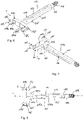
- Fig. 1 shows a perspective view of a spinal implant in the form of an intervertebral implant 1 and an insertion device 100 for inserting the intervertebral implant 1 into an intervertebral space.
- the intervertebral implant 1 shown in the Figures may be used in particular for anterior lumbar interbody fusion (ALIF). However, the embodiment is not limited to such type of intervertebral implant.
- the intervertebral implant 1 has a body including a substantially vertical side wall 2.
- the side wall 2 is formed monolithically with an inner solid portion 3 and encloses one or more inner hollow spaces 4.
- the hollow spaces 4 are open towards an upper face 5a and a lower face 5b of the intervertebral implant 1.
- the side wall 2 is formed by a front wall 2a, an opposite back wall 2b, a right side wall 2c, and a left side wall 2d, which are monolithically formed, such that the right and left side walls connect the front wall 2a and the back wall 2b with each other.
- the front wall 2a represents an anterior wall and the back wall 2b represents a posterior wall of the intervertebral implant 1.
- the front wall 2a and the back wall 2b may be longer than the right side wall 2c and the left side wall 2d, so that the intervertebral implant 1 may have an elongate outer contour.
- the front wall 2a and the back wall 2b are substantially parallel to each other and define a longitudinal central axis LI of the intervertebral implant.
- the front wall 2a and the back wall 2b may have different heights, such that the top face 5a and the bottom face 5b form an angle, resulting in the intervertebral implant 1 having a wedge shape.
- the front wall 2a may have a height greater than that of the back wall 2b for the correction of lordosis.
- inner walls 6a, 6b may extend from the front wall 2a to the back wall 2b by means of which the hollow spaces 4 are separated from each other. In the embodiment shown, three such hollow spaces 4 are provided, however, the design of the intervertebral implant is not limited to this number.
- the inner walls 6a, 6b may by symmetric with respect to a sagittal plane S that extends vertically through the centers of the front wall 2a and the back wall 2b.
- the solid portion 3 extends from the front wall 2a to a distance from the back wall 2b and has a length in this direction such that connection portions in the form of recesses, as further described below, can be formed in a solid body 3 with depths sufficient for engagement with the insertion device 100.
- the hollow spaces 4 are configured to be filled with bone graft material or biologics.
- engagement portions for example teeth (not shown), may be provided in the upper face 5a and the lower face 5b of the intervertebral implant 1, which may facilitate penetration into the end plates of adjacent vertebral bodies.
- each recesses 10, 10' At the corners that are formed by the transition of the front wall 2a to the left side wall 2b and to the right side wall 2c, recesses 10, 10', respectively are provided that each form an elongate opening 11 in the side wall 2.
- Each recess 10, 10' defines a connection portion for connection with a holding portion of an insertion device or a plate member.
- the two recesses 10, 10' are mirror symmetrical with respect to the sagittal plane S and therefore in the following, only the recess 10 will be described in more detail while in the embodiment, the recess 10' at the opposite corner has a mirror symmetrical design.
- the recess 10 defines a hollow space within the intervertebral implant 1 for receiving a portion of the insertion device.
- the recess 10 extends into the solid portion 3 and forms a corner with an angle of slightly more than 90 therein. Thereby, left and right boundary walls 10a, 10b of the recess 10 form an angle of slightly more than 90 °, for example about up to 100°.
- the recess 10 and the opening 11 may be provided at a middle of the side wall 2 in the height direction. It shall be understood, that the angle may also be about or exactly 100°.
- a width of the recess 10 in the height direction is such that an engagement portion of the insertion device 100 can be introduced in one orientation, but cannot be introduced in a tilted orientation.
- Top and bottom walls of the recess 10 may be planar, and may extend substantially parallel to each other and substantially perpendicular to the side wall 2.
- the opening 11 extends in a circumferential direction from the front wall 2a over the corner between the front wall 2a and the right side wall 2c into the right sidewall.
- a spherically-shaped recess 12 is formed that is configured to receive an engagement portion of the insertion device 100.
- a radius of the spherically-shaped recess 12 matches a radius of an outer surface of the engagement portion of the insertion device.
- An axis R extending through a center of the spherically-shaped recess 12 and parallel to the side wall 2 forms an axis of rotation and more specifically, a pivot axis that enables a pivotal movement between the intervertebral implant 1 and an engagement portion of an insertion device or a plate member as explained in more detail below.
- the boundary walls 10a, 10b that delimit the recess 10 at the end of the opening 11 in the circumferential direction may have a contour that is suitable for guiding engagement with the engagement portion. It may be, for example, substantially cylindrical.
- the boundary wall 10b is substantially perpendicular to the right side wall 2d and the boundary wall 10a extends at a slight angle to the front wall 2a in such a manner that an enlarged portion 10c may formed between the spherical recess 12 and the boundary wall 10a. By means of this, the insertion of the engagement portion of the insertion device may be facilitated.
- the side wall 2 may have, in the region of the elongate opening 11, outer surfaces that are shaped to provide abutment surfaces for an insertion device to achieve a form-fit engagement and/or to provide guiding surfaces for pivotal movement of the insertion device.
- a first abutment surface 21 is provided around the lateral edge of the elongate opening that extends into the right side wall 2c.
- the first abutment surface 21 is in the left sidewall 2d.
- the first abutment surface 21 may be substantially cylindrical with a cylinder axis substantially parallel to the axis of rotation R.
- a second substantially planar abutment surface 22 is provided around the opposite lateral edge of the elongate opening 11 that extends into the front wall 2a.
- a third substantially planar abutment surface 23 may extend around substantially a center of the opening 11 and forms an angle of substantially 45° with the second abutment surface 22.
- the intervertebral implant 1 may include further connection portions in the side wall 2.
- the intervertebral implant has additional recesses 30, 30' at the right side wall 2c and the left side wall 2d, respectively.
- Each recess 30, 30' defines an elongate opening 31 and comprises an inner spherically-shaped recess 32, permitting rotation of an inserted engagement portion therein.
- the recesses 30, 30' are each configured such that an engagement portion of a holding member of an insertion device or a plate member can be inserted in one orientation, but cannot be inserted in a tilted orientation.
- the connection portions 30, 30' permit only a single angle between the implant and the holding portion of the device to be attached. It shall be noted, that the connection portions 30, 30' may also be designed such as to allow a variation in the angle between the insertion device and the implant.
- one or more additional holes 40 may be provided in the front wall 2a.
- the additional holes may be threaded, to receive fixation screws (not shown) for additional fixation of the intervertebral implant 1 with respect to the adjacent vertebral bodies.
- the axes of the additional holes 40 may be inclined with respect to the top face 5a and the bottom face 5b so that fixation screws extending therethrough are configured to engage the end plates of the vertebral bodies, respectively.
- the number and position of the recesses and holes is not limited to the number and position shown in the embodiment but more or less recesses and holes may be provided and the positions may vary.
- the insertion device 100 includes a holding portion 110, a sleeve 120 configured to extend around the holding portion 110 and a handle 130 connected to the holding portion.
- the sleeve 120 defines a longitudinal axis of the insertion device 100.
- the holding portion 110 comprises two holding members 111, 111', the front portions 112, 112' of which form a fork-shaped clamp configured to engage the intervertebral implant 1.
- the holding members 111, 111' each comprise a longitudinal bar 113, 113', wherein the bars 113, 113' are connected at their rear end 114. From the rear end 114 a post 115 with a threaded end portion 116 extends.
- the front portions 112, 112' each include a cross-bar 117, 117' extending transverse to the longitudinal axis in an outward direction. From each outer end of the cross-bar 117, 117' an engagement portion 118, 118' extends in a direction substantially parallel to the longitudinal axis L.
- the cross-bars 117, 117' may have a substantially rectangular cross-section with a height that is preferably smaller than a height of the front wall 2a. The length of the cross-bars 117, 117' is such that the engagement portions 188, 118' can be inserted into the recesses 10, 10'.
- the engagement portions 118, 118' have a substantially spherical segment-shaped end portion 119, 119' with upper and lower surfaces that are substantially flat and parallel to each other.
- An axis F perpendicular to the flat surfaces is substantially perpendicular to the longitudinal axis L.
- the outer surface of the spherical segment-shaped portions 199, 199' may have a small cylindrical portion 119b.
- the engagement portion 118, 118' and in particular the spherical-segment-shaped end portion 119, 119' have a flattened shape with a thickness slightly smaller than a vertical height of the elongate opening 11 to permit insertion of the engagement portion into the recess 10, 10'.
- the engagement portion 118, 118' comprises a narrowing section 119a, 119a' to provide a hook-like shape.
- the enlarged portion 10c may facilitate .the engagement of the engagement portion with the recess 10, 10', respectively, since the spreading apart of the engagement portions required for entering the recesses may be reduced.
- the holding members 111, 111' are separated by a slot 111a that may have a widened section 111b adjacent to the end portion 114.
- the slot 111a renders the holding members 111, 111' deflectable towards each other and apart from each other in a resilient manner.
- An outer surface portion 111c of the holding members 111, 111' adjacent to the cross-bars 117, 117' may be tapered in a direction such that it widens towards the cross-bars 117, 117'.
- the sleeve 120 is configured to extend around the bar-shaped longitudinal portions 113, 113' of the holding portion. It comprises a front end 120a and a rear end with a grip section 121 and an inner thread (not shown), for example in the region of the grip section 121 that is configured to cooperate with the threaded end portion 116 of the holding portion 110. Hence the sleeve 120 is configured to be moved forward and backward in the longitudinal direction by rotating it relative to the holding portion 110. When the sleeve is in the retracted position, its front end 120a has a distance from the cross-bars 117, 177' of the holding member 110 such that the tapered section 111c is at least partially exposed.
- An inner wall 120c adjacent to the front portion 120a of the sleeve 120 slightly tapers outward ( Figs. 11a to 11d ). This enables sliding of the sleeve over the tapered portion 111c.
- longitudinal holes 122 may be provided in the sleeve that may serve for saving weight and/or facilitating cleaning.
- the sleeve 120 may be moved forward and backward by pushing it relative to the holding portion 110.
- the insertion device is configured to have a first configuration in which the engagement portions 118, 118' are spaced apart from each other at a first distance and a second configuration in which the engagement portions 118, 118' are spaced apart at a second distance smaller than the first distance.
- the sleeve In the first configuration the sleeve is at the retracted position. By displacing the sleeve along the longitudinal axis L the slot 111a is narrowed so that the engagement portions 118, 118' are moved towards each other.
- Parts and portions of the intervertebral implant and the insertion device may be made of any material, preferably, however, of a bio-compatible material, such as titanium or stainless steel or any other bio-compatible metal or metal alloy, or plastic material.
- a bio-compatible material such as titanium or stainless steel or any other bio-compatible metal or metal alloy, or plastic material.
- a bio-compatible alloy a NiTi-alloy, for example Nitinol, may be used.
- Other materials can be Magnesium or Magnesium alloys
- bio-compatible plastic materials for use may be for example, Polyether ether ketone (PEEK) or Poly-L-lactide acid (PLLA).
- PEEK Polyether ether ketone
- PLLA Poly-L-lactide acid
- the intervertebral implant 1 and the insertion device will be explained.
- the intervertebral implant is oriented with respect to the insertion device in such a manner that the front portion of the insertion device faces the front wall 2a of the intervertebral implant 1.
- the sleeve 120 is in the retracted position in which the tapered section 111c of the holding portion 110 is substantially free.
- Fig. 10 shows the connected configuration in which the engagement portions 118, 118' have engaged the spherical recess 12 inside the recesses 10, 10'.
- the sleeve 120 has been moved towards the cross-bars 117, 117' over at least a part or most of the tapered portion 111c so that the two engagement portions 118, 118' are pressed towards each other.
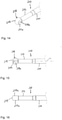
- FIG. 11a the steps of engagement of the intervertebral implant with the insertion device are shown in more detail.
- the insertion device is moved towards the front wall 2a with the sleeve 120 in the retracted position.
- Fig. 11b the outer spherical segment-shaped ends 119, 119' of the engagement portions 118, 118' move through the opening 11 into the recesses 10, 10', respectively.
- the holding members 111, 111' are slightly spread apart.
- the outer ends 119, 119' of the engagement portion are shown in more detail.
- the sleeve 120 is moved towards the cross-bars 117, 117'. Since it slides along the tapered portion 111c, the holding members 111, 111' are pressed towards each other so that the outer ends 119, 119' of the engagement portions 118, 118' are firmly pressed against the wall of the recess 12. By means of this, the connection is fixed.
- the intervertebral implant of this type may be inserted from the anterior side. Once the intervertebral implant has been placed with the insertion device 100 between two vertebral bodies, the insertion device is be removed. This is effected by holding the holding portion 110 with the handle 30 and retracting the sleeve 120. Thereby, the clamping of the engagement portions 118, 118' is loosened and the engagement portions can be disengaged from the implant.
- the height of the front portion 112, 112' of the insertion device is smaller than the height of the front wall 2a of the intervertebral implant 1, the visibility of the intervertebral implant during the insertion process may be improved. Also the width of the insertion device is smaller than the width of the implant which may be helpful in insertion and release of the implant.
- the intervertebral implant 1 is shown together with another embodiment of an insertion device.
- the intervertebral implant 1 in the form of an ALIF-cage has an increased functionality due to the connection portions in form of the recesses 10, 10', 30, 30'.
- the insertion device 200 is an insertion device which may be usually used for implants which are inserted between the vertebrae in an antero-lateral or lateral approach and require in some cases a specific angle or a variation of that angle between the insertion device and the intervertebral implant along the insertion trajectory.
- Fig. 12 shows the insertion device 200 engaging one of the recesses 10, 10' at the corners of the intervertebral implant.
- Fig. 13 shows the insertion device 200 engaging one of the recesses 30, 30' at the left sidewall or the right sidewall of the intervertebral implant.
- the insertion device 200 includes a holding portion 210, a guiding sleeve 220 that receives the holding portion 210 therein, a handle 230, a rotation actuating member (not shown), and an axial position adjusting device 240.
- the holding member 210 is movably guided within the guiding sleeve 220 and may be advanced or retracted with respect to the guiding sleeve 220 by actuating the axial position adjusting device 240. Further, the holding member 210 may be rotated by actuating the rotation actuating member. It shall be noted that axial displacement of the holding member 210 and rotating of the holding 210 may be achieved in various other ways.
- the holding member 210 defines the longitudinal axis L of the insertion device, and has a front portion which is shown in greater detail in Figs. 14 to 16 .
- the front portion includes an engagement portion 218 with a spherical surface 219 that has the shape of a segment of a sphere.
- the spherical surface 219 may be formed by removing opposite segments of the sphere to yield opposite flat surfaces 219a.
- the engagement portion 218 has a flattened shape with a thickness between the flat surfaces 219a that is slightly smaller than a vertical height of the elongate opening 11 and heights of the openings 31 of the optional recesses 30, 30'. This permits insertion of the engagement portion 218 into the recesses 10, 10' and optionally into the recesses 30, 30' of the intervertebral implant 1, in an orientation where the flat surfaces 219a extend perpendicular to the height direction of the sidewall 2.
- a longitudinally extending positioning mark 219b may be provided, that extends parallel to the longitudinal axis L of the insertion device 200.
- the engagement portion 218 is connected to a main portion 211 via a neck portion 212.
- the neck portion 212 has an outer diameter that is smaller than the maximum diameter of the spherical surface portion 219 of the engagement portion 218.
- the main portion 211 may have a greater diameter than the neck portion 212.
- the spherical segment-shaped portion 219 of the engagement portion 218 has a size such that, once the portion 218 has been inserted into the recess 10, 10' and engages the inner spherical recess 12 or into one of the recesses 30, 30' and engages the inner spherical recess 32, the holding member 210 can be tilted by 90° so that the engagement portion 218 is held in the spherical recess 12 or in one of the spherical recesses 32 but can still pivot therein.
- the front portion of the guiding sleeve 220 is shown in greater detail in Figs. 17 to 19 .
- the engagement portion 218 protrudes out of the front portion of the guiding sleeve 220.
- Two opposite cylindrical projections 222 form the outermost end of the guiding sleeve 220.
- the cylindrical projections 222 have a size such that they are insertable to the recesses 10, 10', 30, 30', respectively.
- An end face of the tubular guiding sleeve 220 includes a planar surface 223 and a concave, and more specifically a cylindrical surface 224 that is arranged between the two projections 222 and that has a cylinder axis which is perpendicular to the longitudinal axis L.
- the planar surface 223 thus forms adjacent each projection 222 an abutment surface for abutting against the second abutment surface 22 or the third abutment surface 23 at the sidewall 2 of the intervertebral implant 1 when the guiding sleeve 220 is pressed against the sidewall 2.
- the cylindrical surface 224 forms a small guiding surface that is configured to cooperate with guiding surface 24 at the sidewall 2 of the intervertebral implant 1 to permit a guided rotational movement of the intervertebral implant relative to the insertion device in an angular range.
- a radius of the cylindrical guiding surface 224 corresponds to a radius of the cylindrical guiding surface 24 on the left sidewall 2d of the intervertebral implant 1.
- two opposite positioning flat surfaces 225 may be provided.
- the positioning flat surfaces 225 indicate the position of the cylindrical projection 222, and may serve for orienting the insertion device 200 correctly during the connection with the intervertebral implant 1.
- at least one longitudinally extending positioning mark 226 at an outside of the front portion of the guiding sleeve 220 may further be provided that is 90° offset from the positioning flat surfaces 225 and that indicates the position of the projections 222.
- the holding member 210 When the holding member 210 is inserted into the guiding sleeve 220 and the engagement portion 218 projects out of the front portion of the guiding sleeve 220, the holding member 210 may be pushed forward and retracted by actuating the axial position adjustment device 240.
- the size of the projections 222 is such that the engagement portion 218 can only be retracted between the projections 222 in a 90° upright position of the engagement portion 218.
- the intervertebral implant 1 and the insertion device may be manufactured from the same materials as described before with respect to the combination of the intervertebral implant 1 and the insertion device 100.
- FIG. 20 to 22d The various connection possibilities provided by the recesses 10, 10', 30, 30' increase the possibilities for surgical approaches for insertion of the intervertebral implant 1.
- an angled connection will be described in which the intervertebral implant 1 and the insertion device 200 are connected via the recesses 10 or 10' at the corner of the implant. This connection permits to adjust the angular position between the intervertebral implant 1 and the insertion device 200.
- the intervertebral implant 1 and the insertion device 200 are oriented towards each other in such a manner that the engagement portion 218 faces towards the recess 10' at the corner between the front wall 2a and the left sidewall 2c.
- the engagement portion 218 is oriented such that the flat top and bottom surfaces 219a are substantially perpendicular to the axis of rotation R of the intervertebral implant 1.
- the marking 219b faces towards the upper rim of the opening 11 which facilitates the proper orientation of the engagement portion 218. As illustrated in Fig.
- the engagement portion 218 in this orientation, can be inserted through the opening 11 into the recess 10' until the engagement portion 218 abuts against the inner wall of the spherical recess 12. Then, the engagement portion 218 is rotated until the flat surfaces 219a extend parallel or substantially parallel to the axis of rotation R. In this configuration, the engagement portion 218 is prevented from being removed through the opening 11.
- the guiding sleeve is advanced such that the cylindrical projections 222 extend into the recess 10' through the opening 11.
- the flat abutment surfaces 223 of the guiding sleeve 220 abut against the flat abutment surface 23 surrounding the opening as shown for example in Figs.
- the holding member 220 is pulled backward and fixed in the pulled back position to lock the parts together.
- the connection may be locked by actuating a locking mechanism that holds the guiding sleeve 220 in this position.
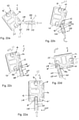
- Figs. 22a and 22b show in a cross-sectional view the relation of the intervertebral implant 1 and the insertion device 200 with respect to each other during the insertion and fixation step.
- Fig. 22a shows the proper orientation before inserting the engagement portion 218 into the recess 10'
- Fig. 22b corresponds to the position in which the engagement portion has been rotated by 90° within the recess 12.
- the connection portion 218 is rotated in the spherical recess 12 until one of the flat surfaces 219a abuts against the boundary wall 10b of the recess 10' so that the insertion device 200 extends away from the left sidewall 2c of the intervertebral implant.
- the insertion device and the intervertebral implant form an angle of substantially 0°.
- the engagement portion 280 is rotated in the spherical recess 12 until the other one of the flat surfaces 219a abuts against the boundary wall 10a of the recess 10' such that the insertion device extends from the front wall 2a of the intervertebral implant 1.
- the angle between the intervertebral implant 1 and the insertion device is a little more than 90°, due to the inclination of the boundary wall 10a with respect to the front wall 2a.
- Fig. 22e shows the engagement of the intervertebral implant through the additional recess 30' in left sidewall 2d.
- the implant and the insertion device can be locked together in a single position.
- the engagement portion 218 when the engagement portion 218 is in the 90° tilted upright position, the engagement portion 218 is freely pivotable around the rotational axis R so that a plurality of angular positions of the insertion device 200 relative to the intervertebral implant can be adjusted.
- engagement portion 218 presses from inside against a wall of the recess 10 or 10', so that the insertion device and the implant are pulled together.
- various angular positions can be fixed.
- predefined angular positions such as 0°, 90° or 45° as shown in the exemplary embodiment can be fixed in a form-fit manner.
- Intermediate angular positions may also be achieved by the aid of the guiding surfaces 24, 224 and a force-fit connection. Loosening the fixation allows adjustments to the relative position between the intervertebral implant and the insertion device without disconnecting the insertion device from the implant. This may be particularly useful for lateral or anterior approaches to the intervertebral space.
- an ALIF intervertebral implant may in some situations be inserted from the anterior side with the insertion device 100 and in other situations laterally using the insertion device 200.
- the intervertebral implant and the insertion devices open a variety of possibilities to engage the intervertebral implant and to insert the intervertebral implant into the intervertebral space. Once the intervertebral implant is finally implanted in the intervertebral space, the insertion device is removed.
- the intervertebral implant 1 is in this embodiment the same as in the previous embodiments.
- the plate assembly 300 includes a plate member 310 that is connectable via a holding member 330, a sleeve 340 and a locking member 350 to the intervertebral implant 1.
- the plate assembly 300 further includes bone fixation members 360 in the form of bone screws that are configured to engage the adjacent vertebrae between which the intervertebral implant 1 is sandwiched.
- the bone fixation members 360 each may be secured against backing out using locking members 370.
- the plate member 310 will be described in more detail referring additionally to Figs. 25 to 28 .
- the plate member 310 has an elongate shape with a top surface 310a and an opposite bottom surface 310b. It shall be understood that the plate member can have any shape, however, the elongate shape is useful for an application along the spinal column. End portions 310c, 310d of the plate member may be rounded, more specifically may have a substantially cylindrical outer contour. In addition, the plate member 310 may have a shallow curvature along its length so that it is slightly convexly shaped in a direction away from the intervertebral implant in the connected state.
- two holes 311 are provided that serve for guiding through the fixation members 360, respectively.
- the holes 311 each have adjacent the bottom surface 310b a threaded portion 311a that is configured to cooperate with a thread on the shank 361 of the fixation member 360.
- a side recess 311b is provided at each side of the threaded portion 311 a that faces towards the outer ends 310c, 310d. The side recesses 311b permit to orient the shank 361 of the fixation members 360 outward in an oblique manner to enable insertion into a portion of the adjacent vertebra.
- each of the holes 311 Adjacent to the top surface 310a each of the holes 311 comprises a recess 311c with a greater diameter than that of the threaded portion 311a which serves for housing a head 362 of the fixation member 360, respectively, and for accommodating the locking member 370.
- the recess 311c may have in at least a portion thereof an inner thread that cooperates with an outer thread of the locking member 370.
- a central hole 312 is provided that is located substantially at the middle of the plate member 310 in the longitudinal direction.
- the bottom surface 310b comprises a substantially flat portion 313 that may serve as an abutment for the sleeve 340.
- a first unthreaded portion 312a of the central hole 312 is formed that is substantially cylindrical and has an inner diameter that permits a portion of the holding member 330 to extend therethrough.
- a substantially cylindrical threadless recess 312b forms part of the hole 312 which has a greater diameter than the threadless portion 312a.
- the threadless recess 312b serves for accommodating at least a portion of the locking member 350.
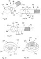
- the holding member 330 will be explained in detail referring additionally to Figs. 29 to 31 .
- the holding member 330 comprises an engagement portion 338 that is shaped substantially as a segment of a sphere, i.e. it has a spherical outer surface 339 and flat top and bottom surfaces 339a.
- the shape of the engagement portion 338 is highly similar to the shape of the engagement portion 218 of the insertion device according to Figs. 12 to 19 .
- the engagement portion 338 is configured to engage the recesses 10, 10' or 30, 30' in the same manner as the engagement portion of the insertion device 200.
- a marking 339b may be provided at at least one of the flat top and bottom surfaces 339a of the engagement portion 338.
- the engagement portion 338 is connected, for example monolithically, to a rod or bar 331.
- the bar 331 has a threaded end portion 332 opposite to the engagement portion 338.
- a thread-free section 333 is provided on which the sleeve 340 is placed.
- a thickened section 334 may be provided that has a slightly greater outer diameter than the thread-free section 333.
- the thickened section 334 comprises an edge 335 from which two projections 335a, offset by 180°, extend that are configured to enter between two projections of the sleeve 340.
- the length of the rod portion 331 of the holding member 330 is such that when the sleeve 340 is mounted thereon, the threaded end portions 332 extends through the first unthreaded portion 312a of the central hole 312 of the plate member 310 into the recess 312b in order to be engaged by the locking member 350.
- an coaxial hole 336 preferably with an internal thread, for connection an insertion device, such as a threaded rod thereto (not shown).
- the locking member 350 is a nut-like member comprising a central threaded hole 351 in which the threaded end portion 332 of the holding member can be screwed.
- a cylindrical rim 352 is formed that has a size such that it fits into the recess 312b of the central hole 312 provided in the plate member 310.
- a plurality of elongate circumferentially arranged pockets 353 are provided that extend completely through the cylindrical rim 352 and that serve for engagement with a drive tool.
- the nut-like member Opposite to the lower side 352a of the cylindrical rim 352 the nut-like member comprises a cylindrical portion 354 with a smaller outer diameter. The length of this portion is such that once the locking member 350 is in the recess 312b of the central hole 312, the cylindrical portion 354 extends out of the top surface 310a of the plate member so that it can be detected more easily with a tool.
- the sleeve member 340 will be described.
- the sleeve member is configured to be placed onto the thread-free portion 333 of the holding member 330.
- a rear end 340a of the sleeve member 340 is substantially flat and is configured to abut against the flat surface portion 313 of the plate member 310.
- the front portion of the sleeve member comprises two substantially cylindrical projections 341 that are offset by 180° and configured to extend through the opening 11 into the recesses 10, 10' or 30, 30' of the intervertebral implant 1.
- an abutment surface 342 is formed that is configured to cooperate with an abutment surface at the intervertebral implant, for example with the abutment surface 23 in the corner of the intervertebral implant.
- An outer contour of the sleeve 340 may be substantially square-shaped with rounded edges. Any other contour, for example a cylindrical shape may also be possible.
- the projections 335 of the holding member 335 are configured to fit in-between the projections 341 of the sleeve member 340. It shall be noted that the sleeve and the plate member can also be monolithic.
- the sleeve 340 is mounted onto the rod-like portion 331, specifically onto the threadless 333 of the holding member 330 and the threaded end portion 332 is guided through the central hole 312 of the plate member 310 until it projects into the recess 312b. Then the locking member 350 is screwed onto the threaded end portion 332 to connect the holding member 330 to the plate member 310.
- the engagement portion 338 is oriented such that the flat surfaces 319a extend substantially vertical to the axis of rotation of the spherical recess 12.
- the engagement portion 338 is tilted by 90° so that it cannot be removed through the openings 11 or 31. Moreover, the holding member 330 is moved backward so that the engagement portion 338 abuts against the inner wall of the recess 10, 10', 31 or 31'. The projections 335a move into the space between the projections 341 of the sleeve member 340 and thus inhibit rotation of the engagement portion 338.
- the locking member 350 is tightened with respect to the holding member 30 so that the sleeve 340 is firmly pressed with its abutment surface 340a against the flat surface 313 of the plate member and with the abutment surface 342 against the abutment surface 23 of the intervertebral implant, as depicted in Fig. 24 .
- a relatively thin at least partially threaded rod may guided through the locking member 350 and inserted into the threaded hole 336 of the holding member 330.
- the plate member 310 can be easily and quickly connected to the intervertebral implant 1.
- various angles as in the previous embodiment can be adjusted between the holding member 330 and the intervertebral implant 1, depending on the selection of the recess 10, 10', 30 or 30'. In this way, the plate can assume various orientations with respect to the intervertebral implant which enhances the possibilities of temporary stabilization.
- the plate member 310 may be additionally fixed by the bone fixation members 360 which are inserted into the holes 311 and screwed into a portion of the vertebra.
- the locking member 370 may be used to press onto the head 362 of the fixation member 360.
- the plate member 310 remains implanted.
- the plate member 310 can also serve for a temporary fixation and can be later removed. Once the bone fixation members 360 have been removed, the unlocking of the holding member 330 from the intervertebral implant 1 can be achieved easily by slightly pushing in the the engagement portion 338, tilting it and withdrawing the engagement portion from the recess 10, 10' or 30, 30'.
- Fig. 38 shows a further embodiment of an intervertebral implant together with the plate assembly 300.
- the intervertebral implant 1' in this case is an lateral cage which is elongate and has the recesses 10, 10' for connection with the insertion device and/or the plate only on one of the short sides of the elongate implant.
- a single recess 10 may be provided at the corner of a long side to a short side of the implant and a single recess 30 on the short side may be provided which is used in the depicted embodiment for connection to the plate member 310.
- Figs. 39 to 41 show a further embodiment of the spinal implant in the form of a placeholder 1" for a vertebra or portions thereof.
- the placeholder comprises a cylindrical tube with a tube axis T and with openings 1a in the wall.
- Prongs 2 may be formed at either end to engage the end plates of the vertebral bodies between which the placeholder 1" shall be placed.
- an opening 11 that is elongate in the circumferential direction.
- the inside of the tube behind the opening 11 provides a hollow space for receiving an engagement portion of an insertion device or of a plate assembly.
- the placeholder 1" can be used together with the insertion device 200 according to Figs. 12 to 19 .
- the engagement portion 218 is inserted in the orientation in which the flat surfaces 219a are perpendicular to the cylinder axis of the tube. After insertion, the engagement portion is tilted by 90° so that it is prevented from being removed through the opening 11. Then, the sleeve 220 is advanced to press against the outer wall of the tube and is fixed in this position. Thereafter, the placeholder 1" can be inserted between two vertebrae.
- Fig. 41 shows the connection between a plate member 310' and the placeholder 1".
- the principle of the connection is the same as described with respect to the connection between the placeholder 1" and the insertion device.
- a shorter holding member 330' may be used and the plate member 310' may be straight, i.e. without curvature.
- the spinal implant as shown in the above described embodiments is only an example.
- the contour and shape of the implant may be different according to specific clinical requirements.
- the implant may also be in the form of a three-dimensional network or grid structure that can be manufactured, for example, by 3D printing techniques.
- the implant may be a dummy implant or testing implant that is used for a trial procedure to open the disc space before insertion of the implant that remains in the body.
- connection portions on the implant provided by the recesses may differ.
- only one of the recesses has the specific inner shape which allows to additionally attach the other insertion device.
- the other one of the recesses may be shaped to only provide an abutment for the engagement portion of the insertion device.
- the number, orientation, and/or abutment surfaces may vary.
- the elongate opening can be at another position than at an edge.
- the elongate opening may extend vertically or at an incline. In such a case, the holding portion can be inserted in the upright orientation or inclined orientation and is then tilted. More than two elongate openings may be provided. Also, a number of additional recesses for receiving the insertion device can be more or less than that shown in the described embodiments.
Landscapes
- Health & Medical Sciences (AREA)
- Engineering & Computer Science (AREA)
- Biomedical Technology (AREA)
- Orthopedic Medicine & Surgery (AREA)
- Neurology (AREA)
- Life Sciences & Earth Sciences (AREA)
- Transplantation (AREA)
- Animal Behavior & Ethology (AREA)
- Veterinary Medicine (AREA)
- Public Health (AREA)
- General Health & Medical Sciences (AREA)
- Heart & Thoracic Surgery (AREA)
- Vascular Medicine (AREA)
- Oral & Maxillofacial Surgery (AREA)
- Cardiology (AREA)
- Surgery (AREA)
- Physical Education & Sports Medicine (AREA)
- Nuclear Medicine, Radiotherapy & Molecular Imaging (AREA)
- Medical Informatics (AREA)
- Molecular Biology (AREA)
- Prostheses (AREA)
- Surgical Instruments (AREA)
Abstract
Description
- The invention relates to an implant, in particular to a spinal implant, an insertion device for such an implant and a plate assembly. The implant may be, for example, an intervertebral implant for intervertebral disc replacement in the case of a damaged intervertebral disc or a placeholder for bridging the space of a removed vertebra following vertebrectomy.
- In the case of damaged intervertebral discs, lumbar or thoracic interbody fusion surgery is one of the most commonly performed instrumented spinal fusion surgeries. Among others, known surgical approaches for interbody fusion of the lumbar spine include posterior lumbar interbody fusion (PLIF), transforaminal lumbar interbody fusion (TLIF), anterior lumbar interbody fusion (ALIF), antero-lateral ALIF and lateral interbody fusion as well as oblique lateral interbody fusion.
- An intervertebral implant and a device for inserting the same that are, for example, suitable for TLIF are described in
US 2017/0056194 A1 . The intervertebral implant comprises a top surface, a bottom surface, and a sidewall extending between the top surface and the bottom surface and a hollow space formed within the intervertebral implant and accessible through an elongate opening extending through a recessed portion of the sidewall. The hollow space is shaped to receive an engagement portion of a drive shaft of an insertion tool. The intervertebral implant includes at least two guiding surfaces facing each other and being configured for sliding engagement by a portion of a sleeve of the insertion tool movably holding the drive shaft. -
US 2016/0235546 A1 describes a spacer with temporary fixation which includes the spacer, a plate, an attachment member and a temporary fixation screw. The temporary fixation of the spacer is applicable in a lateral spinal procedure to prevent migration of the spacer while a patient is being rotated after insertion of the spacer. - It is an object underlying the invention to provide an improved or alternative implant, an insertion device therefor, and a fixation device, and systems including the implant and an insertion device or a fixation device such as a plate assembly that are versatile and simple in use and have an enlarged field of application.
- The object is solved by an implant according to
claim 1, by an insertion device according to claim 9, by a plate assembly according toclaim 12 and by systems according toclaims - According to an embodiment in implant, in particular a spinal implant, for example an intervertebral implant or a placeholder for vertebrae includes a body insertable into the space between two bones or bone parts, more particularly between two vertebrae, the body comprising a first face, a second face connected to and opposite to the first face, wherein the body comprises at least one connection portion for connecting the spinal implant to a holding member of an insertion device for the implant or a secondary device such as a plate member. The connection portion comprises a hollow space defined by the body between the first and second faces configured to accommodate an engagement portion of the holding member, the hollow space being accessible from outside the body through an opening formed between the first and second faces. The opening is elongate with a length that is greater than a width in at least a portion thereof such that the engagement portion of the holding member is insertable into the hollow space through the opening when the engagement portion has a first orientation and is prevented from removal from the hollow space when the engagement portion is in a second orientation; and wherein the connection portion is located on the implant and configured in such a way that it permits to selectively connect at least two different holding to the implant.
- The connection portion of the implant, in particular the spinal implant is multi-functional. It is designed such that a holding portion of a further device, such as an insertion instrument or a plate member, which is adapted to cooperate with the connection portion can be inserted and tilted whereafter it is prevented from removal. In addition, other instruments, such as a different insertion device which is suitable for a different surgical insertion approach, may be connected to the implant using the connection portion in a different manner.
- The connection is threadless which renders it robust and easy to establish, disconnect and reconnect.
- The implant, in particular the spinal implant may be an intervertebral implant for disc replacement or a placeholder for bridging the gap in case of removal of one or more vertebrae or portions thereof.
- Due to the increase in functionality, the implant may be particularly useful in the case of difficult anatomical circumstances such as an anterior and lateral approaches to the spine as well as revision surgery.
- According to a further embodiment, an insertion device for inserting the implant described above comprises two holding members each having an engagement portion wherein the holding members form a fork-shaped holding portion of the insertion device and wherein the engagement portions are configured to engage connection portions provided at opposite corners of the implant, respectively. The holding members are configured to move from a first configuration in which the engagement portions have a first distance from each other to a second configuration in which the engagement portions have a second distance from each other smaller than the first distance. A sleeve may be provided around the holding members which is displaceable relative to the holding members such as to move them from the first configuration to the second configuration.
- With such an insertion device the implant, in particular the spinal implant, most suitable an intervertebral implant, may be engaged in a clamp like manner and fixed by the instrument. The implant may then be inserted, for example, in an anterior approach.
- According to a further embodiment, a plate assembly comprises a plate member and a holding member connectable to the plate member wherein the holding member comprises an engagement portion that is configured to engage the connection portion of the spinal implant in a threadless manner. In particular, the plate member may be used as a temporary fixation plate which can provide temporary stability to the spinal region which comprises the implant.
- The threadless connection may also permit the plate member to assume various angular positions relative to the implant, in particular the spinal implant.
- According to a still further embodiment, the implant, in particular the spinal implant comprises a tube member with openings therein which is intended to form a placeholder for one or more removed vertebrae or portions thereof. The hollow space of the connection portion is formed inside the tube.
- According to a still further embodiment, a kit of an implant, in particular a spinal implant as described above with at least two devices out of a group comprising at least two different insertion devices as described hereinafter and a plate assembly.
- Further features and advantages will become apparent from the detailed description of embodiment by means of the accompanying drawings. In the drawings:
- Fig. 1:
- shows a perspective view of a first embodiment of a spinal implant in the form of an intervertebral implant, in particular for the ALIF-procedure and/or antero-lateral ALIF procedure, and a first insertion device therefor.
- Fig. 2:
- shows a perspective view from the top of the intervertebral implant of
Fig. 1 . - Fig. 3
- shows a perspective view from the bottom of the intervertebral implant of
Figs. 1 and2 . - Fig. 4:
- shows a front view of the intervertebral implant of
Figs. 1 to 3 . - Fig. 5:
- shows a cross-sectional view of the intervertebral implant of
Figs. 1 to 4 along line A-A inFig. 4 . - Fig. 6:
- shows a perspective view from the top of a holding portion of the insertion device of
Fig. 1 . - Fig. 7:
- shows a perspective view from the bottom of the holding portion of
Fig. 6 . - Fig. 8:
- shows a top view of the holding portion of
Figs. 6 and 7 . - Fig. 9:
- shows a perspective view of a step of orienting the insertion device and the intervertebral implant of
Figs. 1 to 8 relative to each other for connecting them. - Fig. 10:
- shows a perspective view of a step of engaging the intervertebral implant to
Fig. 9 with the insertion device. - Figs. 11a to 11d:
- show cross-sectional views of steps of engaging the intervertebral implant with the insertion device according to the previous Figures and locking the intervertebral implant relative to the insertion device.
- Fig. 12:
- shows the intervertebral implant as depicted in
Figs. 1 to 11d with a second embodiment of an insertion device in a first mode of connection. - Fig. 13:
- shows a perspective view of the intervertebral implant and insertion device of
Fig. 12 in a second mode of connection. - Fig. 14:
- shows a perspective view from above of a front portion of a holding member of the insertion device of
Figs. 12 and 13 . - Fig. 15:
- shows a side view of the holding member of
Fig. 14 . - Fig. 16:
- shows a side view of the holding member of
Figs. 14 and 15 . - Fig. 17:
- shows a perspective view of a front portion of a locking sleeve of the insertion device of
Figs. 12 and 13 . - Fig. 18:
- shows a side view of the locking sleeve of
Fig. 17 . - Fig. 19:
- shows a top view of the locking sleeve of
Figs. 17 and 18 . - Fig. 20:
- shows a perspective view of a step of orienting the intervertebral implant and the insertion device of
Figs. 12 to 19 relative to each other. - Fig. 21:
- shows a second step of engaging the intervertebral implant with the insertion device of
Fig. 12 . - Figs. 22a to 22d:
- show cross-sectional views of of engaging the intervertebral implant as shown in
Fig. 12 with the insertion device as shown inFig. 12 in the first mode of connection in various pivot positions of the intervertebral implant relative to the insertion device. - Fig. 22e:
- shows a cross-sectional view of engaging the intervertebral implant as shown in
Fig. 13 with the insertion device as shown inFig. 13 in the second mode of connection. - Fig. 23:
- shows an exploded perspective view of the intervertebral implant of
Figs. 1 to 22d together with a plate assembly. - Fig. 24:
- shows the intervertebral implant and the plate assembly of
Fig. 23 in an assembled configuration. - Fig. 25:
- shows a perspective view from the top onto the plate member of the plate assembly of
Figs. 23 and 24 . - Fig. 26:
- shows a perspective view from the bottom of the plate member of
Figs. 23 to 25 . - Fig. 27:
- shows a top view of the plate member of
Figs. 23 to 26 . - Fig. 28:
- shows a cross-sectional view of the plate member of
Figs. 23 to 27 along line B-B inFig. 27 . - Fig. 29:
- shows a perspective view from the top onto a holding member of the plate assembly of
Figs. 23 and 24 . - Fig. 30:
- shows a side view of the holding member of
Fig. 29 . - Fig. 31:
- shows a top view of the holding member of
Figs. 29 and 30 . - Fig. 32:
- shows a perspective view from the top onto a locking member of the plate assembly of
Figs. 23 and 24 . - Fig. 33:
- shows a perspective view from the bottom of the locking member of
Fig. 32 . - Fig. 34:
- shows a perspective view from the top of a sleeve member of the plate assembly of
Figs. 23 and 24 . - Fig. 35:
- shows a perspective view from the bottom of the sleeve member of
Fig. 34 . - Fig. 36:
- shows a top view of the sleeve member of
Figs. 34 and 35 . - Fig. 37:
- shows a cross-sectional view of the sleeve member of
Figs. 34 to 36 along line D-D inFig. 36 . - Fig. 38:
- shows a perspective view of the plate assembly of
Figs. 23 and 24 with other embodiment of a spinal implant in the form of another intervertebral implant. - Fig. 39:
- shows a perspective view of a still further embodiment of a spinal implant with an insertion device, the implant being a placeholder, for example used following vertebrectomy.
- Fig. 40:
- shows an enlarged perspective view of a portion of
Fig. 39 . - Fig. 41:
- shows a perspective view of the placeholder of
Figs. 39 and40 together with the plate assembly ofFigs. 23 and 24 . -
Fig. 1 shows a perspective view of a spinal implant in the form of anintervertebral implant 1 and aninsertion device 100 for inserting theintervertebral implant 1 into an intervertebral space. Theintervertebral implant 1 shown in the Figures may be used in particular for anterior lumbar interbody fusion (ALIF). However, the embodiment is not limited to such type of intervertebral implant. Referring in addition in more detail toFigs. 2 to 5 , theintervertebral implant 1 has a body including a substantiallyvertical side wall 2. Theside wall 2 is formed monolithically with an inner solid portion 3 and encloses one or more innerhollow spaces 4. Thehollow spaces 4 are open towards anupper face 5a and alower face 5b of theintervertebral implant 1. - In greater detail, the
side wall 2 is formed by afront wall 2a, an opposite back wall 2b, a right side wall 2c, and aleft side wall 2d, which are monolithically formed, such that the right and left side walls connect thefront wall 2a and the back wall 2b with each other. Thefront wall 2a represents an anterior wall and the back wall 2b represents a posterior wall of theintervertebral implant 1. Thefront wall 2a and the back wall 2b may be longer than the right side wall 2c and theleft side wall 2d, so that theintervertebral implant 1 may have an elongate outer contour. In the embodiment shown, thefront wall 2a and the back wall 2b are substantially parallel to each other and define a longitudinal central axis LI of the intervertebral implant. Moreover, thefront wall 2a and the back wall 2b may have different heights, such that thetop face 5a and thebottom face 5b form an angle, resulting in theintervertebral implant 1 having a wedge shape. For example, thefront wall 2a may have a height greater than that of the back wall 2b for the correction of lordosis. - Optionally, inner walls 6a, 6b may extend from the
front wall 2a to the back wall 2b by means of which thehollow spaces 4 are separated from each other. In the embodiment shown, three suchhollow spaces 4 are provided, however, the design of the intervertebral implant is not limited to this number. The inner walls 6a, 6b may by symmetric with respect to a sagittal plane S that extends vertically through the centers of thefront wall 2a and the back wall 2b. The solid portion 3 extends from thefront wall 2a to a distance from the back wall 2b and has a length in this direction such that connection portions in the form of recesses, as further described below, can be formed in a solid body 3 with depths sufficient for engagement with theinsertion device 100. Thehollow spaces 4 are configured to be filled with bone graft material or biologics. Further, engagement portions, for example teeth (not shown), may be provided in theupper face 5a and thelower face 5b of theintervertebral implant 1, which may facilitate penetration into the end plates of adjacent vertebral bodies. - At the corners that are formed by the transition of the
front wall 2a to the left side wall 2b and to the right side wall 2c, recesses 10, 10', respectively are provided that each form anelongate opening 11 in theside wall 2. Eachrecess 10, 10' defines a connection portion for connection with a holding portion of an insertion device or a plate member. - The two
recesses 10, 10' are mirror symmetrical with respect to the sagittal plane S and therefore in the following, only therecess 10 will be described in more detail while in the embodiment, the recess 10' at the opposite corner has a mirror symmetrical design. Therecess 10 defines a hollow space within theintervertebral implant 1 for receiving a portion of the insertion device. Therecess 10 extends into the solid portion 3 and forms a corner with an angle of slightly more than 90 therein. Thereby, left andright boundary walls 10a, 10b of therecess 10 form an angle of slightly more than 90 °, for example about up to 100°. Therecess 10 and theopening 11 may be provided at a middle of theside wall 2 in the height direction. It shall be understood, that the angle may also be about or exactly 100°. - A width of the
recess 10 in the height direction is such that an engagement portion of theinsertion device 100 can be introduced in one orientation, but cannot be introduced in a tilted orientation. Top and bottom walls of therecess 10 may be planar, and may extend substantially parallel to each other and substantially perpendicular to theside wall 2. Theopening 11 extends in a circumferential direction from thefront wall 2a over the corner between thefront wall 2a and the right side wall 2c into the right sidewall. - In the inside corner of the
recess 10, a spherically-shapedrecess 12 is formed that is configured to receive an engagement portion of theinsertion device 100. As shown in more detail inFigs. 11c and 11d , a radius of the spherically-shapedrecess 12 matches a radius of an outer surface of the engagement portion of the insertion device. An axis R extending through a center of the spherically-shapedrecess 12 and parallel to theside wall 2 forms an axis of rotation and more specifically, a pivot axis that enables a pivotal movement between theintervertebral implant 1 and an engagement portion of an insertion device or a plate member as explained in more detail below. Theboundary walls 10a, 10b that delimit therecess 10 at the end of theopening 11 in the circumferential direction may have a contour that is suitable for guiding engagement with the engagement portion. It may be, for example, substantially cylindrical. The boundary wall 10b is substantially perpendicular to theright side wall 2d and theboundary wall 10a extends at a slight angle to thefront wall 2a in such a manner that an enlarged portion 10c may formed between thespherical recess 12 and theboundary wall 10a. By means of this, the insertion of the engagement portion of the insertion device may be facilitated. - In addition, the
side wall 2 may have, in the region of theelongate opening 11, outer surfaces that are shaped to provide abutment surfaces for an insertion device to achieve a form-fit engagement and/or to provide guiding surfaces for pivotal movement of the insertion device. As depicted more in detail inFig. 5 , afirst abutment surface 21 is provided around the lateral edge of the elongate opening that extends into the right side wall 2c. For the recess 10' thefirst abutment surface 21 is in theleft sidewall 2d. Thefirst abutment surface 21 may be substantially cylindrical with a cylinder axis substantially parallel to the axis of rotation R. A second substantiallyplanar abutment surface 22 is provided around the opposite lateral edge of theelongate opening 11 that extends into thefront wall 2a. Lastly, a third substantiallyplanar abutment surface 23 may extend around substantially a center of theopening 11 and forms an angle of substantially 45° with thesecond abutment surface 22. - Optionally, the
intervertebral implant 1 may include further connection portions in theside wall 2. In the embodiment shown, the intervertebral implant hasadditional recesses 30, 30' at the right side wall 2c and theleft side wall 2d, respectively. Eachrecess 30, 30' defines anelongate opening 31 and comprises an inner spherically-shapedrecess 32, permitting rotation of an inserted engagement portion therein. Therecesses 30, 30' are each configured such that an engagement portion of a holding member of an insertion device or a plate member can be inserted in one orientation, but cannot be inserted in a tilted orientation. Theconnection portions 30, 30' permit only a single angle between the implant and the holding portion of the device to be attached. It shall be noted, that theconnection portions 30, 30' may also be designed such as to allow a variation in the angle between the insertion device and the implant. - Optionally, one or more
additional holes 40 may be provided in thefront wall 2a. The additional holes may be threaded, to receive fixation screws (not shown) for additional fixation of theintervertebral implant 1 with respect to the adjacent vertebral bodies. The axes of theadditional holes 40 may be inclined with respect to thetop face 5a and thebottom face 5b so that fixation screws extending therethrough are configured to engage the end plates of the vertebral bodies, respectively. - It shall be noted that the number and position of the recesses and holes is not limited to the number and position shown in the embodiment but more or less recesses and holes may be provided and the positions may vary.
- Turning now to
Figures 1 and6 to 8 , theinsertion device 100 will be described. Theinsertion device 100 includes a holdingportion 110, asleeve 120 configured to extend around the holdingportion 110 and ahandle 130 connected to the holding portion. Thesleeve 120 defines a longitudinal axis of theinsertion device 100. The holdingportion 110 comprises two holdingmembers 111, 111', thefront portions 112, 112' of which form a fork-shaped clamp configured to engage theintervertebral implant 1. The holdingmembers 111, 111' each comprise alongitudinal bar 113, 113', wherein thebars 113, 113' are connected at theirrear end 114. From the rear end 114 apost 115 with a threadedend portion 116 extends. Thefront portions 112, 112' each include a cross-bar 117, 117' extending transverse to the longitudinal axis in an outward direction. From each outer end of the cross-bar 117, 117' anengagement portion 118, 118' extends in a direction substantially parallel to the longitudinal axis L. The cross-bars 117, 117' may have a substantially rectangular cross-section with a height that is preferably smaller than a height of thefront wall 2a. The length of thecross-bars 117, 117' is such that the engagement portions 188, 118' can be inserted into therecesses 10, 10'. - The
engagement portions 118, 118' have a substantially spherical segment-shapedend portion 119, 119' with upper and lower surfaces that are substantially flat and parallel to each other. An axis F perpendicular to the flat surfaces is substantially perpendicular to the longitudinal axis L. The outer surface of the spherical segment-shaped portions 199, 199' may have a small cylindrical portion 119b. Hence, theengagement portion 118, 118' and in particular the spherical-segment-shapedend portion 119, 119' have a flattened shape with a thickness slightly smaller than a vertical height of theelongate opening 11 to permit insertion of the engagement portion into therecess 10, 10'. Between the spherical segment-shapedend portions 119, 119' and the cross-bar 117, 117' theengagement portion 118, 118' comprises anarrowing section recess 10, 10', respectively, since the spreading apart of the engagement portions required for entering the recesses may be reduced. - The holding
members 111, 111' are separated by a slot 111a that may have a widened section 111b adjacent to theend portion 114. The slot 111a renders the holdingmembers 111, 111' deflectable towards each other and apart from each other in a resilient manner. Anouter surface portion 111c of the holdingmembers 111, 111' adjacent to thecross-bars 117, 117' may be tapered in a direction such that it widens towards thecross-bars 117, 117'. When thesleeve 120 moves towards thecross-bars 117, 117' this results in compression of the holdingmembers 11, 11' towards each other which narrows the slot 111a and brings theengagement portions 118, 118' closer towards each other. - The
sleeve 120 is configured to extend around the bar-shapedlongitudinal portions 113, 113' of the holding portion. It comprises afront end 120a and a rear end with agrip section 121 and an inner thread (not shown), for example in the region of thegrip section 121 that is configured to cooperate with the threadedend portion 116 of the holdingportion 110. Hence thesleeve 120 is configured to be moved forward and backward in the longitudinal direction by rotating it relative to the holdingportion 110. When the sleeve is in the retracted position, itsfront end 120a has a distance from thecross-bars 117, 177' of the holdingmember 110 such that the taperedsection 111c is at least partially exposed. Aninner wall 120c adjacent to thefront portion 120a of thesleeve 120 slightly tapers outward (Figs. 11a to 11d ). This enables sliding of the sleeve over the taperedportion 111c. Moreover,longitudinal holes 122 may be provided in the sleeve that may serve for saving weight and/or facilitating cleaning. In a modification, thesleeve 120 may be moved forward and backward by pushing it relative to the holdingportion 110. - The insertion device is configured to have a first configuration in which the
engagement portions 118, 118' are spaced apart from each other at a first distance and a second configuration in which theengagement portions 118, 118' are spaced apart at a second distance smaller than the first distance. In the first configuration the sleeve is at the retracted position. By displacing the sleeve along the longitudinal axis L the slot 111a is narrowed so that theengagement portions 118, 118' are moved towards each other. - Parts and portions of the intervertebral implant and the insertion device may be made of any material, preferably, however, of a bio-compatible material, such as titanium or stainless steel or any other bio-compatible metal or metal alloy, or plastic material. As bio-compatible alloy, a NiTi-alloy, for example Nitinol, may be used. Other materials can be Magnesium or Magnesium alloys, bio-compatible plastic materials for use may be for example, Polyether ether ketone (PEEK) or Poly-L-lactide acid (PLLA). The parts can be made of the same or of different materials from one another.
- Next, the operation of the
intervertebral implant 1 and the insertion device will be explained. As shown inFig. 9 , the intervertebral implant is oriented with respect to the insertion device in such a manner that the front portion of the insertion device faces thefront wall 2a of theintervertebral implant 1. Thesleeve 120 is in the retracted position in which the taperedsection 111c of the holdingportion 110 is substantially free. -
Fig. 10 shows the connected configuration in which theengagement portions 118, 118' have engaged thespherical recess 12 inside therecesses 10, 10'. In this configuration, thesleeve 120 has been moved towards thecross-bars 117, 117' over at least a part or most of the taperedportion 111c so that the twoengagement portions 118, 118' are pressed towards each other. - Referring to
Figs. 11a to 11d , the steps of engagement of the intervertebral implant with the insertion device are shown in more detail. InFig. 11a , the insertion device is moved towards thefront wall 2a with thesleeve 120 in the retracted position. InFig. 11b the outer spherical segment-shaped ends 119, 119' of theengagement portions 118, 118' move through theopening 11 into therecesses 10, 10', respectively. As they slide along theinclined boundary walls 10a the holdingmembers 111, 111' are slightly spread apart. As depicted inFig. 11c , the outer ends 119, 119' of the engagement portion. 118, 118' have entered thespherical recesses 12 and clamp the implant between them. Finally, as shown inFig. 11d , thesleeve 120 is moved towards thecross-bars 117, 117'. Since it slides along the taperedportion 111c, the holdingmembers 111, 111' are pressed towards each other so that the outer ends 119, 119' of theengagement portions 118, 118' are firmly pressed against the wall of therecess 12. By means of this, the connection is fixed. - In the clinical use, the intervertebral implant of this type may be inserted from the anterior side. Once the intervertebral implant has been placed with the
insertion device 100 between two vertebral bodies, the insertion device is be removed. This is effected by holding the holdingportion 110 with thehandle 30 and retracting thesleeve 120. Thereby, the clamping of theengagement portions 118, 118' is loosened and the engagement portions can be disengaged from the implant. - Since the height of the
front portion 112, 112' of the insertion device is smaller than the height of thefront wall 2a of theintervertebral implant 1, the visibility of the intervertebral implant during the insertion process may be improved. Also the width of the insertion device is smaller than the width of the implant which may be helpful in insertion and release of the implant. - Referring to
Figs. 12 and 13 , theintervertebral implant 1 is shown together with another embodiment of an insertion device. Theintervertebral implant 1 in the form of an ALIF-cage has an increased functionality due to the connection portions in form of therecesses insertion device 200 is an insertion device which may be usually used for implants which are inserted between the vertebrae in an antero-lateral or lateral approach and require in some cases a specific angle or a variation of that angle between the insertion device and the intervertebral implant along the insertion trajectory.Fig. 12 shows theinsertion device 200 engaging one of therecesses 10, 10' at the corners of the intervertebral implant.Fig. 13 shows theinsertion device 200 engaging one of therecesses 30, 30' at the left sidewall or the right sidewall of the intervertebral implant. - Referring now in addition to
Figs. 14 to 19 , theinsertion device 200 will be described in greater detail. Theinsertion device 200 includes a holdingportion 210, a guidingsleeve 220 that receives the holdingportion 210 therein, ahandle 230, a rotation actuating member (not shown), and an axialposition adjusting device 240. The holdingmember 210 is movably guided within the guidingsleeve 220 and may be advanced or retracted with respect to the guidingsleeve 220 by actuating the axialposition adjusting device 240. Further, the holdingmember 210 may be rotated by actuating the rotation actuating member. It shall be noted that axial displacement of the holdingmember 210 and rotating of the holding 210 may be achieved in various other ways. - The holding
member 210 defines the longitudinal axis L of the insertion device, and has a front portion which is shown in greater detail inFigs. 14 to 16 . The front portion includes anengagement portion 218 with aspherical surface 219 that has the shape of a segment of a sphere. Thespherical surface 219 may be formed by removing opposite segments of the sphere to yield oppositeflat surfaces 219a. Hence, theengagement portion 218 has a flattened shape with a thickness between theflat surfaces 219a that is slightly smaller than a vertical height of theelongate opening 11 and heights of theopenings 31 of theoptional recesses 30, 30'. This permits insertion of theengagement portion 218 into therecesses 10, 10' and optionally into therecesses 30, 30' of theintervertebral implant 1, in an orientation where theflat surfaces 219a extend perpendicular to the height direction of thesidewall 2. - On at least one, and preferably on both, of the
flat surfaces 219a a longitudinally extending positioning mark 219b may be provided, that extends parallel to the longitudinal axis L of theinsertion device 200. - The
engagement portion 218 is connected to amain portion 211 via aneck portion 212. Theneck portion 212 has an outer diameter that is smaller than the maximum diameter of thespherical surface portion 219 of theengagement portion 218. Themain portion 211 may have a greater diameter than theneck portion 212. The spherical segment-shapedportion 219 of theengagement portion 218 has a size such that, once theportion 218 has been inserted into therecess 10, 10' and engages the innerspherical recess 12 or into one of therecesses 30, 30' and engages the innerspherical recess 32, the holdingmember 210 can be tilted by 90° so that theengagement portion 218 is held in thespherical recess 12 or in one of thespherical recesses 32 but can still pivot therein. - The front portion of the guiding
sleeve 220 is shown in greater detail inFigs. 17 to 19 . When the holdingmember 210 is arranged in the guidingsleeve 220, theengagement portion 218 protrudes out of the front portion of the guidingsleeve 220. Two oppositecylindrical projections 222 form the outermost end of the guidingsleeve 220. Thecylindrical projections 222 have a size such that they are insertable to therecesses tubular guiding sleeve 220 includes aplanar surface 223 and a concave, and more specifically acylindrical surface 224 that is arranged between the twoprojections 222 and that has a cylinder axis which is perpendicular to the longitudinal axis L. Theplanar surface 223 thus forms adjacent eachprojection 222 an abutment surface for abutting against thesecond abutment surface 22 or thethird abutment surface 23 at thesidewall 2 of theintervertebral implant 1 when the guidingsleeve 220 is pressed against thesidewall 2. Thecylindrical surface 224 forms a small guiding surface that is configured to cooperate with guidingsurface 24 at thesidewall 2 of theintervertebral implant 1 to permit a guided rotational movement of the intervertebral implant relative to the insertion device in an angular range. Hence, a radius of thecylindrical guiding surface 224 corresponds to a radius of the cylindrical guidingsurface 24 on theleft sidewall 2d of theintervertebral implant 1. - At an outer wall of the guiding
sleeve 220 adjacent to thecylindrical projections 222 in a longitudinal direction, two opposite positioningflat surfaces 225 may be provided. The positioningflat surfaces 225 indicate the position of thecylindrical projection 222, and may serve for orienting theinsertion device 200 correctly during the connection with theintervertebral implant 1. Moreover, at least one longitudinally extendingpositioning mark 226 at an outside of the front portion of the guidingsleeve 220 may further be provided that is 90° offset from the positioningflat surfaces 225 and that indicates the position of theprojections 222. - When the holding
member 210 is inserted into the guidingsleeve 220 and theengagement portion 218 projects out of the front portion of the guidingsleeve 220, the holdingmember 210 may be pushed forward and retracted by actuating the axialposition adjustment device 240. The size of theprojections 222 is such that theengagement portion 218 can only be retracted between theprojections 222 in a 90° upright position of theengagement portion 218. - The
intervertebral implant 1 and the insertion device may be manufactured from the same materials as described before with respect to the combination of theintervertebral implant 1 and theinsertion device 100. - Next, the operation of the
intervertebral implant 1 and theinsertion device 200 will be explained referring toFigs. 20 to 22d . The various connection possibilities provided by therecesses intervertebral implant 1. First, with reference toFigs. 20 to 22d , an angled connection will be described in which theintervertebral implant 1 and theinsertion device 200 are connected via therecesses 10 or 10' at the corner of the implant. This connection permits to adjust the angular position between theintervertebral implant 1 and theinsertion device 200. - As depicted in
Fig. 20 , theintervertebral implant 1 and theinsertion device 200 are oriented towards each other in such a manner that theengagement portion 218 faces towards the recess 10' at the corner between thefront wall 2a and the left sidewall 2c. Theengagement portion 218 is oriented such that the flat top andbottom surfaces 219a are substantially perpendicular to the axis of rotation R of theintervertebral implant 1. The marking 219b faces towards the upper rim of theopening 11 which facilitates the proper orientation of theengagement portion 218. As illustrated inFig. 21 , in this orientation, theengagement portion 218 can be inserted through theopening 11 into the recess 10' until theengagement portion 218 abuts against the inner wall of thespherical recess 12. Then, theengagement portion 218 is rotated until theflat surfaces 219a extend parallel or substantially parallel to the axis of rotation R. In this configuration, theengagement portion 218 is prevented from being removed through theopening 11. For locking the connection, the guiding sleeve is advanced such that thecylindrical projections 222 extend into the recess 10' through theopening 11. InFig. 21 , the flat abutment surfaces 223 of the guidingsleeve 220 abut against theflat abutment surface 23 surrounding the opening as shown for example inFigs. 2 and 3 , so that the angle is between the longitudinal axis L of theinsertion device 200 and theintervertebral implant 1 is about 45°. The holdingmember 220 is pulled backward and fixed in the pulled back position to lock the parts together. The connection may be locked by actuating a locking mechanism that holds the guidingsleeve 220 in this position. -
Figs. 22a and 22b show in a cross-sectional view the relation of theintervertebral implant 1 and theinsertion device 200 with respect to each other during the insertion and fixation step. Hence,Fig. 22a shows the proper orientation before inserting theengagement portion 218 into the recess 10' andFig. 22b corresponds to the position in which the engagement portion has been rotated by 90° within therecess 12. InFig. 22c , theconnection portion 218 is rotated in thespherical recess 12 until one of theflat surfaces 219a abuts against the boundary wall 10b of the recess 10' so that theinsertion device 200 extends away from the left sidewall 2c of the intervertebral implant. In this configuration, the insertion device and the intervertebral implant form an angle of substantially 0°. InFig. 22d , the engagement portion 280 is rotated in thespherical recess 12 until the other one of theflat surfaces 219a abuts against theboundary wall 10a of the recess 10' such that the insertion device extends from thefront wall 2a of theintervertebral implant 1. In this configuration, the angle between theintervertebral implant 1 and the insertion device is a little more than 90°, due to the inclination of theboundary wall 10a with respect to thefront wall 2a. -
Fig. 22e shows the engagement of the intervertebral implant through the additional recess 30' inleft sidewall 2d. In this configuration, the implant and the insertion device can be locked together in a single position. - Generally, in use, when the
engagement portion 218 is in the 90° tilted upright position, theengagement portion 218 is freely pivotable around the rotational axis R so that a plurality of angular positions of theinsertion device 200 relative to the intervertebral implant can be adjusted. When the holdingmember 210 is retracted with theengagement portion 218 being in the upright position,engagement portion 218 presses from inside against a wall of therecess 10 or 10', so that the insertion device and the implant are pulled together. Thereby, various angular positions can be fixed. With the abutment surfaces, predefined angular positions, such as 0°, 90° or 45° as shown in the exemplary embodiment can be fixed in a form-fit manner. Intermediate angular positions may also be achieved by the aid of the guiding surfaces 24, 224 and a force-fit connection. Loosening the fixation allows adjustments to the relative position between the intervertebral implant and the insertion device without disconnecting the insertion device from the implant. This may be particularly useful for lateral or anterior approaches to the intervertebral space. - By means of the aforementioned steps and with a suitable combination of the intervertebral implant and the appropriate insertion device various access paths to an intervertebral space can be realized with one single type of intervertebral implant. In particular, an ALIF intervertebral implant may in some situations be inserted from the anterior side with the
insertion device 100 and in other situations laterally using theinsertion device 200. - Only by way of example, in a surgical method, access is made to the damaged disc, the disc is removed, and the intervertebral implant filled with bone graft is inserted. The spinal segment is then stabilized, for example, using pedicle screws and rods. The intervertebral implant and the insertion devices according to embodiments of the invention open a variety of possibilities to engage the intervertebral implant and to insert the intervertebral implant into the intervertebral space. Once the intervertebral implant is finally implanted in the intervertebral space, the insertion device is removed.
- Referring to
Figs. 23 to 37 , an embodiment of the intervertebral implant and a plate assembly will be described. Theintervertebral implant 1 is in this embodiment the same as in the previous embodiments. Theplate assembly 300 includes aplate member 310 that is connectable via a holdingmember 330, asleeve 340 and a lockingmember 350 to theintervertebral implant 1. Theplate assembly 300 further includesbone fixation members 360 in the form of bone screws that are configured to engage the adjacent vertebrae between which theintervertebral implant 1 is sandwiched. Thebone fixation members 360 each may be secured against backing out using lockingmembers 370. - The
plate member 310 will be described in more detail referring additionally toFigs. 25 to 28 . Theplate member 310 has an elongate shape with atop surface 310a and an opposite bottom surface 310b. It shall be understood that the plate member can have any shape, however, the elongate shape is useful for an application along the spinal column.End portions plate member 310 may have a shallow curvature along its length so that it is slightly convexly shaped in a direction away from the intervertebral implant in the connected state. At a distance from theend portions holes 311 are provided that serve for guiding through thefixation members 360, respectively. Theholes 311 each have adjacent the bottom surface 310b a threadedportion 311a that is configured to cooperate with a thread on theshank 361 of thefixation member 360. A side recess 311b is provided at each side of the threadedportion 311 a that faces towards the outer ends 310c, 310d. The side recesses 311b permit to orient theshank 361 of thefixation members 360 outward in an oblique manner to enable insertion into a portion of the adjacent vertebra. Adjacent to thetop surface 310a each of theholes 311 comprises a recess 311c with a greater diameter than that of the threadedportion 311a which serves for housing ahead 362 of thefixation member 360, respectively, and for accommodating the lockingmember 370. The recess 311c may have in at least a portion thereof an inner thread that cooperates with an outer thread of the lockingmember 370. - Between the
holes 311 acentral hole 312 is provided that is located substantially at the middle of theplate member 310 in the longitudinal direction. In the region of thecentral hole 312, the bottom surface 310b comprises a substantiallyflat portion 313 that may serve as an abutment for thesleeve 340. Adjacent to the abutment afirst unthreaded portion 312a of thecentral hole 312 is formed that is substantially cylindrical and has an inner diameter that permits a portion of the holdingmember 330 to extend therethrough. At the opposite side a substantially cylindrical threadless recess 312b forms part of thehole 312 which has a greater diameter than thethreadless portion 312a. The threadless recess 312b serves for accommodating at least a portion of the lockingmember 350. - The holding
member 330 will be explained in detail referring additionally toFigs. 29 to 31 . The holdingmember 330 comprises anengagement portion 338 that is shaped substantially as a segment of a sphere, i.e. it has a sphericalouter surface 339 and flat top andbottom surfaces 339a. The shape of theengagement portion 338 is highly similar to the shape of theengagement portion 218 of the insertion device according toFigs. 12 to 19 . Hence, theengagement portion 338 is configured to engage therecesses insertion device 200. A marking 339b may be provided at at least one of the flat top andbottom surfaces 339a of theengagement portion 338. If the holdingportion 330 is oriented with the marking 339b facing toward the upper rim of theopening 11 of therecess 10, the holdingportion 330 is in the correct orientation for insertion. Theengagement portion 338 is connected, for example monolithically, to a rod orbar 331. Thebar 331 has a threadedend portion 332 opposite to theengagement portion 338. Between theengagement portion 338 and the threaded end portion 332 a thread-free section 333 is provided on which thesleeve 340 is placed. Between theengagement 338 and the thread-free section 333 of the holding member 330 a thickenedsection 334 may be provided that has a slightly greater outer diameter than the thread-free section 333. The thickenedsection 334 comprises anedge 335 from which twoprojections 335a, offset by 180°, extend that are configured to enter between two projections of thesleeve 340. The length of therod portion 331 of the holdingmember 330 is such that when thesleeve 340 is mounted thereon, the threadedend portions 332 extends through thefirst unthreaded portion 312a of thecentral hole 312 of theplate member 310 into the recess 312b in order to be engaged by the lockingmember 350. At the threadedend portion 332 of the holding member, ancoaxial hole 336, preferably with an internal thread, for connection an insertion device, such as a threaded rod thereto (not shown). - The locking
member 350 is a nut-like member comprising a central threadedhole 351 in which the threadedend portion 332 of the holding member can be screwed. Around the central threaded hole 351 acylindrical rim 352 is formed that has a size such that it fits into the recess 312b of thecentral hole 312 provided in theplate member 310. In addition, a plurality of elongate circumferentially arrangedpockets 353 are provided that extend completely through thecylindrical rim 352 and that serve for engagement with a drive tool. Opposite to thelower side 352a of thecylindrical rim 352 the nut-like member comprises acylindrical portion 354 with a smaller outer diameter. The length of this portion is such that once the lockingmember 350 is in the recess 312b of thecentral hole 312, thecylindrical portion 354 extends out of thetop surface 310a of the plate member so that it can be detected more easily with a tool. - Referring to
Figs. 34 to 37 , thesleeve member 340 will be described. The sleeve member is configured to be placed onto the thread-free portion 333 of the holdingmember 330. Arear end 340a of thesleeve member 340 is substantially flat and is configured to abut against theflat surface portion 313 of theplate member 310. The front portion of the sleeve member comprises two substantiallycylindrical projections 341 that are offset by 180° and configured to extend through theopening 11 into therecesses intervertebral implant 1. Between theprojections 341 anabutment surface 342 is formed that is configured to cooperate with an abutment surface at the intervertebral implant, for example with theabutment surface 23 in the corner of the intervertebral implant. An outer contour of thesleeve 340 may be substantially square-shaped with rounded edges. Any other contour, for example a cylindrical shape may also be possible. Theprojections 335 of the holdingmember 335 are configured to fit in-between theprojections 341 of thesleeve member 340. It shall be noted that the sleeve and the plate member can also be monolithic. - In the assembled state, the
sleeve 340 is mounted onto the rod-like portion 331, specifically onto thethreadless 333 of the holdingmember 330 and the threadedend portion 332 is guided through thecentral hole 312 of theplate member 310 until it projects into the recess 312b. Then the lockingmember 350 is screwed onto the threadedend portion 332 to connect the holdingmember 330 to theplate member 310. For connecting the plate assembly to the intervertebral implant after the implant has been inserted into the intervertebral space, theengagement portion 338 is oriented such that the flat surfaces 319a extend substantially vertical to the axis of rotation of thespherical recess 12. Once the engagement portion 318 has been introduced into therecess openings engagement portion 338 is tilted by 90° so that it cannot be removed through theopenings member 330 is moved backward so that theengagement portion 338 abuts against the inner wall of therecess projections 335a move into the space between theprojections 341 of thesleeve member 340 and thus inhibit rotation of theengagement portion 338. Thereafter, the lockingmember 350 is tightened with respect to the holdingmember 30 so that thesleeve 340 is firmly pressed with itsabutment surface 340a against theflat surface 313 of the plate member and with theabutment surface 342 against theabutment surface 23 of the intervertebral implant, as depicted inFig. 24 . For manipulating the holdingmember 330 such as insertion into therecess 10 and rotation, a relatively thin at least partially threaded rod may guided through the lockingmember 350 and inserted into the threadedhole 336 of the holdingmember 330. - Due to the threadless connection, the
plate member 310 can be easily and quickly connected to theintervertebral implant 1. In addition, various angles as in the previous embodiment can be adjusted between the holdingmember 330 and theintervertebral implant 1, depending on the selection of therecess plate member 310 may be additionally fixed by thebone fixation members 360 which are inserted into theholes 311 and screwed into a portion of the vertebra. The lockingmember 370 may be used to press onto thehead 362 of thefixation member 360. - In one method of use, the
plate member 310 remains implanted. Theplate member 310 can also serve for a temporary fixation and can be later removed. Once thebone fixation members 360 have been removed, the unlocking of the holdingmember 330 from theintervertebral implant 1 can be achieved easily by slightly pushing in the theengagement portion 338, tilting it and withdrawing the engagement portion from therecess -
Fig. 38 shows a further embodiment of an intervertebral implant together with theplate assembly 300. The intervertebral implant 1' in this case is an lateral cage which is elongate and has therecesses 10, 10' for connection with the insertion device and/or the plate only on one of the short sides of the elongate implant. For example, asingle recess 10 may be provided at the corner of a long side to a short side of the implant and asingle recess 30 on the short side may be provided which is used in the depicted embodiment for connection to theplate member 310. -
Figs. 39 to 41 show a further embodiment of the spinal implant in the form of aplaceholder 1" for a vertebra or portions thereof. The placeholder comprises a cylindrical tube with a tube axis T and with openings 1a in the wall.Prongs 2 may be formed at either end to engage the end plates of the vertebral bodies between which theplaceholder 1" shall be placed. - In the wall of the
placeholder 1" there is anopening 11 that is elongate in the circumferential direction. The inside of the tube behind theopening 11 provides a hollow space for receiving an engagement portion of an insertion device or of a plate assembly. - As can be seen in
Figs. 39 and40 , theplaceholder 1" can be used together with theinsertion device 200 according toFigs. 12 to 19 . Theengagement portion 218 is inserted in the orientation in which theflat surfaces 219a are perpendicular to the cylinder axis of the tube. After insertion, the engagement portion is tilted by 90° so that it is prevented from being removed through theopening 11. Then, thesleeve 220 is advanced to press against the outer wall of the tube and is fixed in this position. Thereafter, theplaceholder 1" can be inserted between two vertebrae. -
Fig. 41 shows the connection between a plate member 310' and theplaceholder 1". The principle of the connection is the same as described with respect to the connection between theplaceholder 1" and the insertion device. Depending on the clinical situation, a shorter holding member 330' may be used and the plate member 310' may be straight, i.e. without curvature. - Various other modifications of the spacer and/or the insertion device and/or the plate assembly may further be made without departing from the scope of the invention.
- The spinal implant as shown in the above described embodiments is only an example. The contour and shape of the implant may be different according to specific clinical requirements. For example, the implant may also be in the form of a three-dimensional network or grid structure that can be manufactured, for example, by 3D printing techniques. In a further modified embodiment, the implant may be a dummy implant or testing implant that is used for a trial procedure to open the disc space before insertion of the implant that remains in the body.
- The number of connection portions on the implant provided by the recesses may differ. For example, for the first embodiment it is sufficient that only one of the recesses has the specific inner shape which allows to additionally attach the other insertion device. The other one of the recesses may be shaped to only provide an abutment for the engagement portion of the insertion device.
- The number, orientation, and/or abutment surfaces may vary. In some embodiments, the elongate opening can be at another position than at an edge. Still further, the elongate opening may extend vertically or at an incline. In such a case, the holding portion can be inserted in the upright orientation or inclined orientation and is then tilted. More than two elongate openings may be provided. Also, a number of additional recesses for receiving the insertion device can be more or less than that shown in the described embodiments.
Claims (15)
- An implant, in particular a spinal implant, more particularly an intervertebral implant or a placeholder for vertebrae or portions thereof, includinga body insertable into space between two bone parts or vertebrae, the body comprising a first face (5a), a second face (5a) connected to and opposite to the first face,wherein the body comprises at least one connection portion (10, 10', 30, 30') for connecting the implant (1, 1'. 1") to a holding member (110, 210, 330) of an insertion device (100, 200) for the implant or a secondary device such as a plate member (310),wherein the connection portion (10, 10', 30, 30') comprises a hollow space defined by the body between the first and second faces configured to accommodate an engagement portion (118, 118'; 218; 338) of the holding member, the hollow space being accessible from outside the body though an opening (11, 31) formed between the first and second faces;wherein the opening (11, 31) is elongate such that the engagement portion of the holding device is insertable into the hollow space through the opening when the engagement portion has a first orientation and is prevented from removal from the hollow space when the engagement portion is in a second orientation; andwherein the connection portion (10, 10', 30, 30') is located in or on the implant and configured in such a way that it permits to selectively connect at least two different holding members (110, 210, 330) to the implant.
- The implant of claim 1, wherein the hollow space comprises a spherical portion (12) and wherein an axis of rotation (R) extends between the first face (5a) and the second face (5b) and through a center of the spherical portion and wherein preferably the axis of rotation is substantially parallel to a sidewall (2) that extends between the first and second faces.
- The implant of claim 2, wherein the opening (11) extends around the axis of rotation (R) and has a first contour configured to facilitate pivoting of the spinal implant (1, 1', 1") relative to the holding member (110, 210, 330) about the axis of rotation to a first angular position and to a second angular position when the engagement portion (218; 338) of the holding member is in the hollow space.
- The implant of claim 3, wherein the at least two different holding members are associated with at least two out of a group comprising at least two different insertion devices and a plate assembly.
- The implant of one of claims 2 to 4, wherein the sidewall (2, 2a) has two corners each corner located at an end of a length portion of the sidewall and wherein the connection portion (10, 10') is located at one of the corners.
- The implant of claim 5, wherein the connection portion is a first connection portion (10) and wherein a second connection portion (10') is provided at the other one of the corners preferably wherein the second connection portion is substantially mirror symmetrical to the first connection portion with respect to a plane (S) extending through a center of the sidewall between the corners and substantially perpendicular to the length portion of the sidewall (2, 2a).
- The implant of one of claim 6, wherein first and second connection portions (10, 10') are configured to be engaged by a two holding members (118, 118'), respectively, that form a substantially fork-shaped holding portion (110) of an insertion device for inserting the implant.
- The implant of one of claims 1 to 7, further comprising at least one third connection portion (30, 30') that is configured to be engaged by an engagement portion (218, 338) of a holding portion (210, 330) of an insertion device or a further device such as a plate assembly, wherein the connection portion is configured to be engaged so that the holding portion and the implant can form only a single angle with respect to each other.
- An insertion device for inserting the implant of one of claims 6 to 8, the insertion device (100) comprising two holding members (111, 111') having each an engagement portion (118, 118') wherein the holding members form a substantially fork-shaped holding portion and wherein the engagement portions are configured to engage the connection portions at the respective corners, and wherein the holding members (111, 111') are configured to move from a first configuration in which the engagement portions have a first distance to a second configuration in which the engagement portions have a second distance from each other smaller than the first distance.
- The insertion device of claim 9, wherein a sleeve (120) is provided around the holding members (111, 111') which is displaceable relative to the holding members such as to move them from the first configuration to the second configuration.
- A system of an implant of one of claims 5 to 8 and an insertion device of one of claims 9 or 10, wherein in the first configuration, the holding members (111, 111') are configured to engage the connection portions (10, 10') without clamping the implant and in the second configuration the holding members are configured to engage the connection portions and clamp the implant.
- A plate assembly for connecting to the implant of one of claims 1 to 8, comprising a plate member (310) and a holding member (330) connectable to the plate member wherein the holding member comprises an engagement portion (338) that is configured to engage the connection portion in a threadless manner.
- The plate assembly of claim 12, further comprising a locking member (350) configured to lock the engagement portion (338) of the holding member (330) in the connection portion (10, 10', 30, 30') of the implant.
- A system of a implant of one of claims 1 to 8 and a plate assembly of one of claims 12 or 13, further including a pivot inhibiting structure (335a, 341) that inhibits pivoting of the engagement portion (338) from the second configuration to the first configuration before locking when the engagement portion is in the hollow space in the second configuration.
- A kit comprising an implant according to one of claims 1 to 8 and at least two out of the group comprising an insertion device (100) according to one of claims 9 or 10, an insertion device (200) having only a single holding member and and a plate assembly (300) of one of claims claims 12 or 13.
Priority Applications (5)
| Application Number | Priority Date | Filing Date | Title |
|---|---|---|---|
| EP20197497.9A EP3970645B1 (en) | 2020-09-22 | 2020-09-22 | Implant, insertion device and plate assembly |
| CN202111090829.1A CN114246710A (en) | 2020-09-22 | 2021-09-17 | Implant, insertion device and plate assembly |
| JP2021152391A JP7616974B2 (en) | 2020-09-22 | 2021-09-17 | Implant, insertion device for inserting the implant, system of implant and insertion device, plate assembly for connecting to the implant, system of implant and plate assembly, and kits comprising same |
| US17/479,376 US12208016B2 (en) | 2020-09-22 | 2021-09-20 | Implant, insertion device, and plate assembly |
| US19/003,901 US20250186216A1 (en) | 2020-09-22 | 2024-12-27 | Implant, insertion device, and plate assembly |
Applications Claiming Priority (1)
| Application Number | Priority Date | Filing Date | Title |
|---|---|---|---|
| EP20197497.9A EP3970645B1 (en) | 2020-09-22 | 2020-09-22 | Implant, insertion device and plate assembly |
Publications (2)
| Publication Number | Publication Date |
|---|---|
| EP3970645A1 true EP3970645A1 (en) | 2022-03-23 |
| EP3970645B1 EP3970645B1 (en) | 2025-06-11 |
Family
ID=72615609
Family Applications (1)
| Application Number | Title | Priority Date | Filing Date |
|---|---|---|---|
| EP20197497.9A Active EP3970645B1 (en) | 2020-09-22 | 2020-09-22 | Implant, insertion device and plate assembly |
Country Status (4)
| Country | Link |
|---|---|
| US (2) | US12208016B2 (en) |
| EP (1) | EP3970645B1 (en) |
| JP (1) | JP7616974B2 (en) |
| CN (1) | CN114246710A (en) |
Families Citing this family (1)
| Publication number | Priority date | Publication date | Assignee | Title |
|---|---|---|---|---|
| GB2640755B (en) * | 2024-06-06 | 2026-05-20 | Nordic Health Service Oy | Bone screw and systems for bone fusion |
Citations (9)
| Publication number | Priority date | Publication date | Assignee | Title |
|---|---|---|---|---|
| FR2822674A1 (en) * | 2001-04-03 | 2002-10-04 | Scient X | STABILIZED INTERSOMATIC MELTING SYSTEM FOR VERTEBERS |
| US20080051890A1 (en) * | 2006-08-11 | 2008-02-28 | Warsaw Orthopedic, Inc. | Intervertebral Implants with Attachable Flanges and Methods of Use |
| WO2008085521A1 (en) * | 2007-01-11 | 2008-07-17 | Warsaw Orthopedic, Inc. | Adjustable insertion device for a vertebral implant |
| EP2055270A1 (en) * | 2007-10-30 | 2009-05-06 | Kilian Kraus | Handling tool for a medical implant, medical implant and kit including a handling tool and an implant |
| WO2015081142A1 (en) * | 2013-11-26 | 2015-06-04 | Xenco Medical, Llc | Lock and release implant delivery system |
| EP2992846A1 (en) * | 2014-09-03 | 2016-03-09 | Aesculap Implant Systems, LLC | Fastener, spinal interbody system including same |
| US20160235546A1 (en) | 2014-02-27 | 2016-08-18 | Alphatec Spine, Inc. | Spacer with Temporary Fixation Plate |
| US20170056194A1 (en) | 2015-08-26 | 2017-03-02 | Timo Biedermann | Intervertebral implant and device for inserting an intervertebral implant |
| US20170100260A1 (en) * | 2015-10-12 | 2017-04-13 | Institute for Musculoskeletal Science and Education, Ltd. | Insertion tool for implant and methods of use |
Family Cites Families (19)
| Publication number | Priority date | Publication date | Assignee | Title |
|---|---|---|---|---|
| JP4255234B2 (en) * | 2000-02-22 | 2009-04-15 | ウォーソー・オーソペディック・インコーポレーテッド | Anterior insertion type bone graft and driver device |
| US20060229627A1 (en) | 2004-10-29 | 2006-10-12 | Hunt Margaret M | Variable angle spinal surgery instrument |
| FR2861582B1 (en) | 2003-10-29 | 2006-02-10 | Eurosurgical | INTERSOMATIC CAGE FOR LUMBAR FUSION FIRST TRANSFORAMINAL AND CAGE HOLDER DEVICE |
| US7935148B2 (en) * | 2006-01-09 | 2011-05-03 | Warsaw Orthopedic, Inc. | Adjustable insertion device for a vertebral implant |
| US20070213826A1 (en) | 2006-03-08 | 2007-09-13 | Seaspine, Inc. | Intervertebral spacer and insertion tool providing multiple angles of insertion |
| BRPI0814609A2 (en) * | 2007-07-19 | 2015-01-27 | Synthes Gmbh | CLAMP TO FIX A BONE ANCHOR TO A ROD, AND A HOLDER TO MOUNT ON A VERTEB. |
| US8545566B2 (en) | 2008-10-13 | 2013-10-01 | Globus Medical, Inc. | Articulating spacer |
| FR2948277B1 (en) | 2009-07-27 | 2012-11-16 | Medicrea International | ASSEMBLY COMPRISING AN INTERVERTEBRAL IMPLANT FOR IMMOBILIZING A VERTEBRA IN RELATION TO ANOTHER AND A POSITION INSTRUMENT OF THIS IMPLANT |
| CN102647961B (en) | 2009-11-05 | 2015-11-25 | 斯恩蒂斯有限公司 | From pivotable vertebra implantation piece and pertinent instruments |
| US8956414B2 (en) | 2010-04-21 | 2015-02-17 | Spinecraft, LLC | Intervertebral body implant, instrument and method |
| TWI465229B (en) | 2011-02-14 | 2014-12-21 | Wiltrom Co Ltd | Interbody fusion cage |
| ES2555552T3 (en) * | 2011-06-14 | 2016-01-04 | Biedermann Technologies Gmbh & Co. Kg | Intervertebral implant |
| US9687356B1 (en) | 2011-10-07 | 2017-06-27 | Nuvasive, Inc. | Spinal fusion implants and related methods |
| US10182921B2 (en) * | 2012-11-09 | 2019-01-22 | DePuy Synthes Products, Inc. | Interbody device with opening to allow packing graft and other biologics |
| US20170095240A9 (en) * | 2013-10-07 | 2017-04-06 | Warsaw Orthopedic, Inc. | Spinal implant system and method for lumbar and lumbosacral fusion |
| US9283091B2 (en) * | 2013-10-07 | 2016-03-15 | Warsaw Orthopedic, Inc. | Spinal implant system and method |
| US9364341B2 (en) * | 2014-01-09 | 2016-06-14 | Warsaw Orthopedic, Inc. | Spinal implant system and method |
| US10765529B2 (en) | 2015-12-18 | 2020-09-08 | Ctl Medical Corporation | Articulating intervertebral devices, related tools, systems, and methods |
| US20170231782A1 (en) * | 2016-02-12 | 2017-08-17 | Mi4Spine, Llc | Spinal fusion spacer with integrated graft delivery |
-
2020
- 2020-09-22 EP EP20197497.9A patent/EP3970645B1/en active Active
-
2021
- 2021-09-17 JP JP2021152391A patent/JP7616974B2/en active Active
- 2021-09-17 CN CN202111090829.1A patent/CN114246710A/en active Pending
- 2021-09-20 US US17/479,376 patent/US12208016B2/en active Active
-
2024
- 2024-12-27 US US19/003,901 patent/US20250186216A1/en active Pending
Patent Citations (9)
| Publication number | Priority date | Publication date | Assignee | Title |
|---|---|---|---|---|
| FR2822674A1 (en) * | 2001-04-03 | 2002-10-04 | Scient X | STABILIZED INTERSOMATIC MELTING SYSTEM FOR VERTEBERS |
| US20080051890A1 (en) * | 2006-08-11 | 2008-02-28 | Warsaw Orthopedic, Inc. | Intervertebral Implants with Attachable Flanges and Methods of Use |
| WO2008085521A1 (en) * | 2007-01-11 | 2008-07-17 | Warsaw Orthopedic, Inc. | Adjustable insertion device for a vertebral implant |
| EP2055270A1 (en) * | 2007-10-30 | 2009-05-06 | Kilian Kraus | Handling tool for a medical implant, medical implant and kit including a handling tool and an implant |
| WO2015081142A1 (en) * | 2013-11-26 | 2015-06-04 | Xenco Medical, Llc | Lock and release implant delivery system |
| US20160235546A1 (en) | 2014-02-27 | 2016-08-18 | Alphatec Spine, Inc. | Spacer with Temporary Fixation Plate |
| EP2992846A1 (en) * | 2014-09-03 | 2016-03-09 | Aesculap Implant Systems, LLC | Fastener, spinal interbody system including same |
| US20170056194A1 (en) | 2015-08-26 | 2017-03-02 | Timo Biedermann | Intervertebral implant and device for inserting an intervertebral implant |
| US20170100260A1 (en) * | 2015-10-12 | 2017-04-13 | Institute for Musculoskeletal Science and Education, Ltd. | Insertion tool for implant and methods of use |
Also Published As
| Publication number | Publication date |
|---|---|
| JP2022051708A (en) | 2022-04-01 |
| US12208016B2 (en) | 2025-01-28 |
| US20250186216A1 (en) | 2025-06-12 |
| JP7616974B2 (en) | 2025-01-17 |
| CN114246710A (en) | 2022-03-29 |
| EP3970645B1 (en) | 2025-06-11 |
| US20220087830A1 (en) | 2022-03-24 |
Similar Documents
| Publication | Publication Date | Title |
|---|---|---|
| US12318304B2 (en) | Lateral spondylolisthesis reduction cage | |
| US11452613B2 (en) | Vertebral implants and methods for installation thereof | |
| US9925063B2 (en) | Interbody device and plate for spinal stabilization and instruments for positioning same | |
| US7815681B2 (en) | Orthopedic support locating or centering feature and method | |
| WO2012021584A2 (en) | Interbody spinal implants with extravertebral support plates | |
| US20250302638A1 (en) | Intervertebral implant and insertion device therefor | |
| JP2024500784A (en) | Tethered intervertebral implant | |
| US20250186216A1 (en) | Implant, insertion device, and plate assembly | |
| US20220409389A1 (en) | Interbody implant with adjusting shims |
Legal Events
| Date | Code | Title | Description |
|---|---|---|---|
| PUAI | Public reference made under article 153(3) epc to a published international application that has entered the european phase |
Free format text: ORIGINAL CODE: 0009012 |
|
| STAA | Information on the status of an ep patent application or granted ep patent |
Free format text: STATUS: REQUEST FOR EXAMINATION WAS MADE |
|
| 17P | Request for examination filed |
Effective date: 20210707 |
|
| AK | Designated contracting states |
Kind code of ref document: A1 Designated state(s): AL AT BE BG CH CY CZ DE DK EE ES FI FR GB GR HR HU IE IS IT LI LT LU LV MC MK MT NL NO PL PT RO RS SE SI SK SM TR |
|
| STAA | Information on the status of an ep patent application or granted ep patent |
Free format text: STATUS: EXAMINATION IS IN PROGRESS |
|
| 17Q | First examination report despatched |
Effective date: 20240409 |
|
| GRAP | Despatch of communication of intention to grant a patent |
Free format text: ORIGINAL CODE: EPIDOSNIGR1 |
|
| STAA | Information on the status of an ep patent application or granted ep patent |
Free format text: STATUS: GRANT OF PATENT IS INTENDED |
|
| INTG | Intention to grant announced |
Effective date: 20241105 |
|
| GRAJ | Information related to disapproval of communication of intention to grant by the applicant or resumption of examination proceedings by the epo deleted |
Free format text: ORIGINAL CODE: EPIDOSDIGR1 |
|
| STAA | Information on the status of an ep patent application or granted ep patent |
Free format text: STATUS: EXAMINATION IS IN PROGRESS |
|
| GRAP | Despatch of communication of intention to grant a patent |
Free format text: ORIGINAL CODE: EPIDOSNIGR1 |
|
| STAA | Information on the status of an ep patent application or granted ep patent |
Free format text: STATUS: GRANT OF PATENT IS INTENDED |
|
| INTG | Intention to grant announced |
Effective date: 20250228 |
|
| GRAS | Grant fee paid |
Free format text: ORIGINAL CODE: EPIDOSNIGR3 |
|
| GRAA | (expected) grant |
Free format text: ORIGINAL CODE: 0009210 |
|
| STAA | Information on the status of an ep patent application or granted ep patent |
Free format text: STATUS: THE PATENT HAS BEEN GRANTED |
|
| P01 | Opt-out of the competence of the unified patent court (upc) registered |
Free format text: CASE NUMBER: APP_17642/2025 Effective date: 20250410 |
|
| AK | Designated contracting states |
Kind code of ref document: B1 Designated state(s): AL AT BE BG CH CY CZ DE DK EE ES FI FR GB GR HR HU IE IS IT LI LT LU LV MC MK MT NL NO PL PT RO RS SE SI SK SM TR |
|
| REG | Reference to a national code |
Ref country code: GB Ref legal event code: FG4D |
|
| REG | Reference to a national code |
Ref country code: CH Ref legal event code: EP |
|
| REG | Reference to a national code |
Ref country code: IE Ref legal event code: FG4D |
|
| REG | Reference to a national code |
Ref country code: DE Ref legal event code: R096 Ref document number: 602020052548 Country of ref document: DE |
|
| REG | Reference to a national code |
Ref country code: CH Ref legal event code: U11 Free format text: ST27 STATUS EVENT CODE: U-0-0-U10-U11 (AS PROVIDED BY THE NATIONAL OFFICE) Effective date: 20251001 |
|
| PG25 | Lapsed in a contracting state [announced via postgrant information from national office to epo] |
Ref country code: ES Free format text: LAPSE BECAUSE OF FAILURE TO SUBMIT A TRANSLATION OF THE DESCRIPTION OR TO PAY THE FEE WITHIN THE PRESCRIBED TIME-LIMIT Effective date: 20250611 Ref country code: FI Free format text: LAPSE BECAUSE OF FAILURE TO SUBMIT A TRANSLATION OF THE DESCRIPTION OR TO PAY THE FEE WITHIN THE PRESCRIBED TIME-LIMIT Effective date: 20250611 |
|
| PGFP | Annual fee paid to national office [announced via postgrant information from national office to epo] |
Ref country code: DE Payment date: 20250924 Year of fee payment: 6 |
|
| REG | Reference to a national code |
Ref country code: LT Ref legal event code: MG9D |
|
| PG25 | Lapsed in a contracting state [announced via postgrant information from national office to epo] |
Ref country code: NO Free format text: LAPSE BECAUSE OF FAILURE TO SUBMIT A TRANSLATION OF THE DESCRIPTION OR TO PAY THE FEE WITHIN THE PRESCRIBED TIME-LIMIT Effective date: 20250911 Ref country code: GR Free format text: LAPSE BECAUSE OF FAILURE TO SUBMIT A TRANSLATION OF THE DESCRIPTION OR TO PAY THE FEE WITHIN THE PRESCRIBED TIME-LIMIT Effective date: 20250912 |
|
| REG | Reference to a national code |
Ref country code: NL Ref legal event code: MP Effective date: 20250611 |
|
| PG25 | Lapsed in a contracting state [announced via postgrant information from national office to epo] |
Ref country code: BG Free format text: LAPSE BECAUSE OF FAILURE TO SUBMIT A TRANSLATION OF THE DESCRIPTION OR TO PAY THE FEE WITHIN THE PRESCRIBED TIME-LIMIT Effective date: 20250611 |
|
| PGFP | Annual fee paid to national office [announced via postgrant information from national office to epo] |
Ref country code: GB Payment date: 20250808 Year of fee payment: 6 |
|
| PG25 | Lapsed in a contracting state [announced via postgrant information from national office to epo] |
Ref country code: HR Free format text: LAPSE BECAUSE OF FAILURE TO SUBMIT A TRANSLATION OF THE DESCRIPTION OR TO PAY THE FEE WITHIN THE PRESCRIBED TIME-LIMIT Effective date: 20250611 |
|
| PG25 | Lapsed in a contracting state [announced via postgrant information from national office to epo] |
Ref country code: RS Free format text: LAPSE BECAUSE OF FAILURE TO SUBMIT A TRANSLATION OF THE DESCRIPTION OR TO PAY THE FEE WITHIN THE PRESCRIBED TIME-LIMIT Effective date: 20250911 |
|
| PG25 | Lapsed in a contracting state [announced via postgrant information from national office to epo] |
Ref country code: LV Free format text: LAPSE BECAUSE OF FAILURE TO SUBMIT A TRANSLATION OF THE DESCRIPTION OR TO PAY THE FEE WITHIN THE PRESCRIBED TIME-LIMIT Effective date: 20250611 |
|
| PG25 | Lapsed in a contracting state [announced via postgrant information from national office to epo] |
Ref country code: NL Free format text: LAPSE BECAUSE OF FAILURE TO SUBMIT A TRANSLATION OF THE DESCRIPTION OR TO PAY THE FEE WITHIN THE PRESCRIBED TIME-LIMIT Effective date: 20250611 |
|
| PG25 | Lapsed in a contracting state [announced via postgrant information from national office to epo] |
Ref country code: PT Free format text: LAPSE BECAUSE OF FAILURE TO SUBMIT A TRANSLATION OF THE DESCRIPTION OR TO PAY THE FEE WITHIN THE PRESCRIBED TIME-LIMIT Effective date: 20251013 |
|
| REG | Reference to a national code |
Ref country code: AT Ref legal event code: MK05 Ref document number: 1801767 Country of ref document: AT Kind code of ref document: T Effective date: 20250611 |
|
| PG25 | Lapsed in a contracting state [announced via postgrant information from national office to epo] |
Ref country code: IS Free format text: LAPSE BECAUSE OF FAILURE TO SUBMIT A TRANSLATION OF THE DESCRIPTION OR TO PAY THE FEE WITHIN THE PRESCRIBED TIME-LIMIT Effective date: 20251011 |
|
| PG25 | Lapsed in a contracting state [announced via postgrant information from national office to epo] |
Ref country code: AT Free format text: LAPSE BECAUSE OF FAILURE TO SUBMIT A TRANSLATION OF THE DESCRIPTION OR TO PAY THE FEE WITHIN THE PRESCRIBED TIME-LIMIT Effective date: 20250611 Ref country code: SM Free format text: LAPSE BECAUSE OF FAILURE TO SUBMIT A TRANSLATION OF THE DESCRIPTION OR TO PAY THE FEE WITHIN THE PRESCRIBED TIME-LIMIT Effective date: 20250611 |
|
| PGFP | Annual fee paid to national office [announced via postgrant information from national office to epo] |
Ref country code: CH Payment date: 20251001 Year of fee payment: 6 |
|
| PG25 | Lapsed in a contracting state [announced via postgrant information from national office to epo] |
Ref country code: CZ Free format text: LAPSE BECAUSE OF FAILURE TO SUBMIT A TRANSLATION OF THE DESCRIPTION OR TO PAY THE FEE WITHIN THE PRESCRIBED TIME-LIMIT Effective date: 20250611 |
|
| PG25 | Lapsed in a contracting state [announced via postgrant information from national office to epo] |
Ref country code: PL Free format text: LAPSE BECAUSE OF FAILURE TO SUBMIT A TRANSLATION OF THE DESCRIPTION OR TO PAY THE FEE WITHIN THE PRESCRIBED TIME-LIMIT Effective date: 20250611 |
|
| PG25 | Lapsed in a contracting state [announced via postgrant information from national office to epo] |
Ref country code: EE Free format text: LAPSE BECAUSE OF FAILURE TO SUBMIT A TRANSLATION OF THE DESCRIPTION OR TO PAY THE FEE WITHIN THE PRESCRIBED TIME-LIMIT Effective date: 20250611 |
|
| PG25 | Lapsed in a contracting state [announced via postgrant information from national office to epo] |
Ref country code: SK Free format text: LAPSE BECAUSE OF FAILURE TO SUBMIT A TRANSLATION OF THE DESCRIPTION OR TO PAY THE FEE WITHIN THE PRESCRIBED TIME-LIMIT Effective date: 20250611 Ref country code: RO Free format text: LAPSE BECAUSE OF FAILURE TO SUBMIT A TRANSLATION OF THE DESCRIPTION OR TO PAY THE FEE WITHIN THE PRESCRIBED TIME-LIMIT Effective date: 20250611 |
|
| REG | Reference to a national code |
Ref country code: DE Ref legal event code: R097 Ref document number: 602020052548 Country of ref document: DE |
|
| PG25 | Lapsed in a contracting state [announced via postgrant information from national office to epo] |
Ref country code: DK Free format text: LAPSE BECAUSE OF FAILURE TO SUBMIT A TRANSLATION OF THE DESCRIPTION OR TO PAY THE FEE WITHIN THE PRESCRIBED TIME-LIMIT Effective date: 20250611 |
|
| PG25 | Lapsed in a contracting state [announced via postgrant information from national office to epo] |
Ref country code: IT Free format text: LAPSE BECAUSE OF FAILURE TO SUBMIT A TRANSLATION OF THE DESCRIPTION OR TO PAY THE FEE WITHIN THE PRESCRIBED TIME-LIMIT Effective date: 20250611 |
|
| PLBE | No opposition filed within time limit |
Free format text: ORIGINAL CODE: 0009261 |
|
| STAA | Information on the status of an ep patent application or granted ep patent |
Free format text: STATUS: NO OPPOSITION FILED WITHIN TIME LIMIT |
|
| REG | Reference to a national code |
Ref country code: CH Ref legal event code: L10 Free format text: ST27 STATUS EVENT CODE: U-0-0-L10-L00 (AS PROVIDED BY THE NATIONAL OFFICE) Effective date: 20260423 |
|
| PG25 | Lapsed in a contracting state [announced via postgrant information from national office to epo] |
Ref country code: LU Free format text: LAPSE BECAUSE OF NON-PAYMENT OF DUE FEES Effective date: 20250922 |
|
| 26N | No opposition filed |
Effective date: 20260312 |
|
| REG | Reference to a national code |
Ref country code: BE Ref legal event code: MM Effective date: 20250930 |
|
| PG25 | Lapsed in a contracting state [announced via postgrant information from national office to epo] |
Ref country code: LT Free format text: LAPSE BECAUSE OF FAILURE TO SUBMIT A TRANSLATION OF THE DESCRIPTION OR TO PAY THE FEE WITHIN THE PRESCRIBED TIME-LIMIT Effective date: 20250611 |
|
| PG25 | Lapsed in a contracting state [announced via postgrant information from national office to epo] |
Ref country code: MC Free format text: LAPSE BECAUSE OF FAILURE TO SUBMIT A TRANSLATION OF THE DESCRIPTION OR TO PAY THE FEE WITHIN THE PRESCRIBED TIME-LIMIT Effective date: 20250611 |
|
| PG25 | Lapsed in a contracting state [announced via postgrant information from national office to epo] |
Ref country code: IE Free format text: LAPSE BECAUSE OF NON-PAYMENT OF DUE FEES Effective date: 20250922 Ref country code: BE Free format text: LAPSE BECAUSE OF NON-PAYMENT OF DUE FEES Effective date: 20250930 |
|
| PG25 | Lapsed in a contracting state [announced via postgrant information from national office to epo] |
Ref country code: FR Free format text: LAPSE BECAUSE OF NON-PAYMENT OF DUE FEES Effective date: 20250930 |
|
| PG25 | Lapsed in a contracting state [announced via postgrant information from national office to epo] |
Ref country code: SE Free format text: LAPSE BECAUSE OF FAILURE TO SUBMIT A TRANSLATION OF THE DESCRIPTION OR TO PAY THE FEE WITHIN THE PRESCRIBED TIME-LIMIT Effective date: 20250611 |