EP3969723B1 - Thrust runner vibration dampening spring in electrical submersible pump - Google Patents
Thrust runner vibration dampening spring in electrical submersible pump Download PDFInfo
- Publication number
- EP3969723B1 EP3969723B1 EP20805373.6A EP20805373A EP3969723B1 EP 3969723 B1 EP3969723 B1 EP 3969723B1 EP 20805373 A EP20805373 A EP 20805373A EP 3969723 B1 EP3969723 B1 EP 3969723B1
- Authority
- EP
- European Patent Office
- Prior art keywords
- shaft
- thrust runner
- wave spring
- thrust
- runner
- Prior art date
- Legal status (The legal status is an assumption and is not a legal conclusion. Google has not performed a legal analysis and makes no representation as to the accuracy of the status listed.)
- Active
Links
Images
Classifications
-
- E—FIXED CONSTRUCTIONS
- E21—EARTH OR ROCK DRILLING; MINING
- E21B—EARTH OR ROCK DRILLING; OBTAINING OIL, GAS, WATER, SOLUBLE OR MELTABLE MATERIALS OR A SLURRY OF MINERALS FROM WELLS
- E21B43/00—Methods or apparatus for obtaining oil, gas, water, soluble or meltable materials or a slurry of minerals from wells
- E21B43/12—Methods or apparatus for controlling the flow of the obtained fluid to or in wells
- E21B43/121—Lifting well fluids
- E21B43/128—Adaptation of pump systems with down-hole electric drives
-
- F—MECHANICAL ENGINEERING; LIGHTING; HEATING; WEAPONS; BLASTING
- F04—POSITIVE - DISPLACEMENT MACHINES FOR LIQUIDS; PUMPS FOR LIQUIDS OR ELASTIC FLUIDS
- F04C—ROTARY-PISTON, OR OSCILLATING-PISTON, POSITIVE-DISPLACEMENT MACHINES FOR LIQUIDS; ROTARY-PISTON, OR OSCILLATING-PISTON, POSITIVE-DISPLACEMENT PUMPS
- F04C15/00—Component parts, details or accessories of machines, pumps or pumping installations, not provided for in groups F04C2/00 - F04C14/00
-
- F—MECHANICAL ENGINEERING; LIGHTING; HEATING; WEAPONS; BLASTING
- F04—POSITIVE - DISPLACEMENT MACHINES FOR LIQUIDS; PUMPS FOR LIQUIDS OR ELASTIC FLUIDS
- F04B—POSITIVE-DISPLACEMENT MACHINES FOR LIQUIDS; PUMPS
- F04B47/00—Pumps or pumping installations specially adapted for raising fluids from great depths, e.g. well pumps
- F04B47/06—Pumps or pumping installations specially adapted for raising fluids from great depths, e.g. well pumps having motor-pump units situated at great depth
-
- F—MECHANICAL ENGINEERING; LIGHTING; HEATING; WEAPONS; BLASTING
- F04—POSITIVE - DISPLACEMENT MACHINES FOR LIQUIDS; PUMPS FOR LIQUIDS OR ELASTIC FLUIDS
- F04C—ROTARY-PISTON, OR OSCILLATING-PISTON, POSITIVE-DISPLACEMENT MACHINES FOR LIQUIDS; ROTARY-PISTON, OR OSCILLATING-PISTON, POSITIVE-DISPLACEMENT PUMPS
- F04C13/00—Adaptations of machines or pumps for special use, e.g. for extremely high pressures
- F04C13/008—Pumps for submersible use, i.e. down-hole pumping
-
- F—MECHANICAL ENGINEERING; LIGHTING; HEATING; WEAPONS; BLASTING
- F04—POSITIVE - DISPLACEMENT MACHINES FOR LIQUIDS; PUMPS FOR LIQUIDS OR ELASTIC FLUIDS
- F04C—ROTARY-PISTON, OR OSCILLATING-PISTON, POSITIVE-DISPLACEMENT MACHINES FOR LIQUIDS; ROTARY-PISTON, OR OSCILLATING-PISTON, POSITIVE-DISPLACEMENT PUMPS
- F04C15/00—Component parts, details or accessories of machines, pumps or pumping installations, not provided for in groups F04C2/00 - F04C14/00
- F04C15/0057—Driving elements, brakes, couplings, transmission specially adapted for machines or pumps
- F04C15/0061—Means for transmitting movement from the prime mover to driven parts of the pump, e.g. clutches, couplings, transmissions
-
- F—MECHANICAL ENGINEERING; LIGHTING; HEATING; WEAPONS; BLASTING
- F04—POSITIVE - DISPLACEMENT MACHINES FOR LIQUIDS; PUMPS FOR LIQUIDS OR ELASTIC FLUIDS
- F04C—ROTARY-PISTON, OR OSCILLATING-PISTON, POSITIVE-DISPLACEMENT MACHINES FOR LIQUIDS; ROTARY-PISTON, OR OSCILLATING-PISTON, POSITIVE-DISPLACEMENT PUMPS
- F04C3/00—Rotary-piston machines or pumps, with non-parallel axes of movement of co-operating members, e.g. of screw type
-
- F—MECHANICAL ENGINEERING; LIGHTING; HEATING; WEAPONS; BLASTING
- F04—POSITIVE - DISPLACEMENT MACHINES FOR LIQUIDS; PUMPS FOR LIQUIDS OR ELASTIC FLUIDS
- F04D—NON-POSITIVE-DISPLACEMENT PUMPS
- F04D13/00—Pumping installations or systems
- F04D13/02—Units comprising pumps and their driving means
- F04D13/06—Units comprising pumps and their driving means the pump being electrically driven
- F04D13/08—Units comprising pumps and their driving means the pump being electrically driven for submerged use
- F04D13/10—Units comprising pumps and their driving means the pump being electrically driven for submerged use adapted for use in mining bore holes
-
- F—MECHANICAL ENGINEERING; LIGHTING; HEATING; WEAPONS; BLASTING
- F04—POSITIVE - DISPLACEMENT MACHINES FOR LIQUIDS; PUMPS FOR LIQUIDS OR ELASTIC FLUIDS
- F04D—NON-POSITIVE-DISPLACEMENT PUMPS
- F04D29/00—Details, component parts, or accessories
- F04D29/04—Shafts or bearings, or assemblies thereof
- F04D29/041—Axial thrust balancing
- F04D29/0413—Axial thrust balancing hydrostatic; hydrodynamic thrust bearings
-
- F—MECHANICAL ENGINEERING; LIGHTING; HEATING; WEAPONS; BLASTING
- F04—POSITIVE - DISPLACEMENT MACHINES FOR LIQUIDS; PUMPS FOR LIQUIDS OR ELASTIC FLUIDS
- F04D—NON-POSITIVE-DISPLACEMENT PUMPS
- F04D29/00—Details, component parts, or accessories
- F04D29/66—Combating cavitation, whirls, noise, vibration or the like; Balancing
- F04D29/669—Combating cavitation, whirls, noise, vibration or the like; Balancing especially adapted for liquid pumps
-
- F—MECHANICAL ENGINEERING; LIGHTING; HEATING; WEAPONS; BLASTING
- F04—POSITIVE - DISPLACEMENT MACHINES FOR LIQUIDS; PUMPS FOR LIQUIDS OR ELASTIC FLUIDS
- F04C—ROTARY-PISTON, OR OSCILLATING-PISTON, POSITIVE-DISPLACEMENT MACHINES FOR LIQUIDS; ROTARY-PISTON, OR OSCILLATING-PISTON, POSITIVE-DISPLACEMENT PUMPS
- F04C2/00—Rotary-piston machines or pumps
- F04C2/08—Rotary-piston machines or pumps of intermeshing-engagement type, i.e. with engagement of co-operating members similar to that of toothed gearing
- F04C2/10—Rotary-piston machines or pumps of intermeshing-engagement type, i.e. with engagement of co-operating members similar to that of toothed gearing of internal-axis type with the outer member having more teeth or tooth-equivalents, e.g. rollers, than the inner member
- F04C2/107—Rotary-piston machines or pumps of intermeshing-engagement type, i.e. with engagement of co-operating members similar to that of toothed gearing of internal-axis type with the outer member having more teeth or tooth-equivalents, e.g. rollers, than the inner member with helical teeth
- F04C2/1071—Rotary-piston machines or pumps of intermeshing-engagement type, i.e. with engagement of co-operating members similar to that of toothed gearing of internal-axis type with the outer member having more teeth or tooth-equivalents, e.g. rollers, than the inner member with helical teeth the inner and outer member having a different number of threads and one of the two being made of elastic materials, e.g. Moineau type
-
- F—MECHANICAL ENGINEERING; LIGHTING; HEATING; WEAPONS; BLASTING
- F04—POSITIVE - DISPLACEMENT MACHINES FOR LIQUIDS; PUMPS FOR LIQUIDS OR ELASTIC FLUIDS
- F04C—ROTARY-PISTON, OR OSCILLATING-PISTON, POSITIVE-DISPLACEMENT MACHINES FOR LIQUIDS; ROTARY-PISTON, OR OSCILLATING-PISTON, POSITIVE-DISPLACEMENT PUMPS
- F04C2240/00—Components
- F04C2240/50—Bearings
-
- F—MECHANICAL ENGINEERING; LIGHTING; HEATING; WEAPONS; BLASTING
- F04—POSITIVE - DISPLACEMENT MACHINES FOR LIQUIDS; PUMPS FOR LIQUIDS OR ELASTIC FLUIDS
- F04D—NON-POSITIVE-DISPLACEMENT PUMPS
- F04D29/00—Details, component parts, or accessories
- F04D29/04—Shafts or bearings, or assemblies thereof
- F04D29/041—Axial thrust balancing
-
- F—MECHANICAL ENGINEERING; LIGHTING; HEATING; WEAPONS; BLASTING
- F04—POSITIVE - DISPLACEMENT MACHINES FOR LIQUIDS; PUMPS FOR LIQUIDS OR ELASTIC FLUIDS
- F04D—NON-POSITIVE-DISPLACEMENT PUMPS
- F04D29/00—Details, component parts, or accessories
- F04D29/66—Combating cavitation, whirls, noise, vibration or the like; Balancing
- F04D29/661—Combating cavitation, whirls, noise, vibration or the like; Balancing especially adapted for elastic fluid pumps
- F04D29/668—Combating cavitation, whirls, noise, vibration or the like; Balancing especially adapted for elastic fluid pumps damping or preventing mechanical vibrations
Definitions
- This disclosure relates in general to electrical submersible well pumps (ESP), particularly to a thrust bearing having a thrust runner keyed to the shaft and having a radially compressible vibration dampening ring between the thrust runner and the shaft.
- ESP electrical submersible well pumps
- a typical ESP includes a pump driven by an electrical motor.
- the motor is filled with a dielectric lubricant for lubricating motor bearings.
- a pressure equalizer reduces a differential between the hydrostatic well fluid pressure and the lubricant pressure.
- the pressure equalizer may be located in a seal section between the motor and the pump.
- the well fluid pump generates axial thrust on a drive shaft extending through the seal section. Both down thrust toward the motor and up thrust away from the motor can occur.
- a thrust bearing unit usually within the seal section, transfers the down thrust and up thrust to the motor.
- the thrust bearing unit includes a thrust runner mounted to the shaft for rotation with the shaft. The thrust runner slides on non-rotating down thrust bearing pads during down thrust, transferring the down thrust on the shaft to the housing. The thrust runner slides against non-rotating up thrust bearing pads during up thrust, transferring the up thrust to the housing.
- the thrust bearing unit may include a screw pump that rotates with the shaft for circulating motor lubricant within the thrust bearing unit.
- the shaft in the seal section is radially supported at its ends by radial bearings.
- the shaft in the seal section may vibrate, particularly at high rotational speeds. Vibration can cause fatigue of components in the seal section. Also, the shaft has a primary mechanical seal at its upper end, and vibration can cause leakage of well fluid into the seal section. The well fluid can migrate through the motor lubricant in the seal section, eventually reaching the motor. Contamination of the motor lubricant in the motor by well fluid can quickly cause failure of the motor.
- the invention provides a submersible pump assembly (ESP) as claimed in claim 1.
- ESP submersible pump assembly
- An annular thrust runner recess is selectively in the runner bore or on the shaft.
- the thrust runner wave spring is located in the thrust runner recess.
- the annular thrust runner recess is on the shaft.
- the annular thrust runner recess may have an upper shoulder facing a lower shoulder.
- the thrust runner wave spring has an axial dimension less than a distance from the lower shoulder to the upper shoulder.
- ESP 11 an electrical well pump assembly (ESP) 11 of a type typically used for oil well pumping operations is illustrated.
- ESP 11 includes a rotary pump 12 that may be a centrifugal pump having a large number of stages, each of the stages having an impeller and a diffuser.
- Pump 12 could also be a progressing cavity pump, which has a helical rotor that rotates within an elastomeric double helical stator. Pump 12 may be suspended in a well on a string of production tubing 13. Pump 12 has an intake 15 and discharges into production tubing 13.
- ESP 11 also includes an electrical motor 17 for driving pump 12.
- Motor 17 connects to pump 12 via a seal section 19, which has means for reducing a pressure differential between lubricant within motor 17 and the hydrostatic pressure of well fluid in the well.
- Intake 15 may be at the lower end of pump 12, in the upper end of seal section 19 or in a separate module.
- ESP 11 may also include a gas separator, and if so intake 15 would be in the gas separator.
- seal section 19 has a shaft 21 extending along a longitudinal axis 23 of a cylindrical housing 25.
- Shaft 21 has a lower splined end (not shown) coupled to a shaft of motor 17 for rotating shaft 21.
- Shaft 21 has an upper splined end (not shown) coupling to a shaft of pump 12 for driving pump 12.
- An upper guide or connector 27 secures by threads to housing 25 and has connecting features on its upper end (not shown) for connecting to pump 12.
- a similar connector or guide is on the lower end of seal section 19 for connecting to motor 17.
- Seal section 19 has a conventional pressure equalizer that is not shown but will normally comprise an elastomeric bag.
- Lubricant from motor 17 communicates through passages in seal section 19 with the interior of the elastomeric bag.
- Well fluid is admitted into the chamber containing the elastomeric bag for imparting hydrostatic well fluid pressure on the elastomeric bag, which in turn applies the hydrostatic pressure to the motor lubricant.
- Seal section 19 also has a primary seal, normally a mechanical face seal, in an upper portion of upper connector 27 for sealing well fluid from contact with the motor lubricant in the interior of seal section 19.
- the seal section 19 has a thrust bearing assembly for transferring down thrust and up thrust imposed on shaft 21 from pump 12 to housing 25. Seal section 19 could include a separate module for the thrust bearing assembly.
- the thrust bearing assembly may have various configurations and in this example has a non-rotating base including a down thrust transfer member 29 secured to housing 25 for non-rotation relative to housing 25. Thrust transfer member 29 may have a helical passage 31 on its exterior to allow the flow of motor lubricant between thrust transfer member 29 and housing 25.
- the base also includes a down thrust bearing 33 mounted on the upper side of thrust transfer member 29 for non- rotation relative to thrust transfer member 29.
- Thrust runner 35 is rigidly secured to shaft 21 above thrust transfer member 29 for rotation in unison with shaft 21.
- Thrust runner 35 is a cylindrical member with bearing pads 37 on its lower side that slidingly engage down thrust bearing 33 to transfer down thrust.
- Thrust runner 35 also transfers any up thrust that may occur on shaft 21 to non-rotating up thrust pads 39.
- Thrust runner 35 has appreciable mass, being much larger in outer diameter than shaft 21. It also has a significant axial dimension from its lower end to its upper end.
- the thrust bearing assembly may also optionally have an inducer or screw pump 41 for circulating motor lubricant.
- screw pump 41 has a helical flight 43 on its exterior that is in close reception with down thrust transfer member bore 45. Screw pump 41 is mounted to shaft 21 for rotation therewith.
- seal section 19 also has radial bearing assemblies at the upper and lower ends of housing 25 for providing radial support to shaft 21.
- Fig. 2 shows only the top bearing assembly, but the bottom bearing assembly will have similar components.
- Those components include a bearing sleeve 47 that rotates with shaft 21.
- Bearing sleeve 47 has an outer diameter in sliding rotational engagement with a non-rotating bushing 49.
- Bushing 49 may be press fit into connector 27.
- Bearing sleeve 47 and bushing 49 may be of carbide material and are immersed in the motor lubricant within seal section 19.
- Seal section 19 has one or more thrust runner tolerance rings or wave springs 51 (two shown) between shaft 21 and thrust runner 35. Seal section 19 may also have one or more screw pump tolerance rings or wave springs 53 (two shown) between shaft 21 and screw pump 41. In addition, seal section 19 may have a radial bearing tolerance ring or wave spring 55 between shaft 21 and bearing sleeve 47. The lower radial bearing (not shown) may also have a tolerance ring or wave spring. The various wave springs 51, 53 and 55 reduce vibration of shaft 21, which might occur particularly at high rotational speeds.
- Wave springs 51, 53 and 55 are located in annular recesses, and in this embodiment, all of the recesses are selectively located on shaft 21.
- Fig. 3 shows a portion of shaft 21 that has an annular recess 57 for receiving one of the shaft runner wave springs 51; the other recesses may be identical.
- Upper and lower shoulders 59, 61 define the upper and lower ends of annular recess 57.
- Upper shoulder 59 faces and may be parallel to lower shoulder 61.
- Upper and lower shoulders 59, 61 define a recess cylindrical surface 63 that has a smaller outer diameter than the outer diameter of shaft 21.
- Shaft 21 also has a keyway groove or shaft slot 65 extending most of its length and parallel with axis 23.
- shaft slot 65 has a radial depth no greater than the radial width of shoulders 57, 59, thus it does not extend through recess cylindrical surface 63.
- Shaft slot 65 does extend through upper and lower shoulders 59, 61.
- a portion of a key 67 extends through shaft slot 65 above and below shoulders 59, 61 and alongside recess cylindrical surface 63.
- Key 67 has an inward facing side 66 that is illustrated as being spaced radially outward a slight distance from recess cylindrical surface 63, but it could touch recess cylindrical surface 63.
- the radial distance from axis 23 to key inward facing side 66 is not less than the radial distance from axis 23 to recess cylindrical surface 63 in this example.
- Fig. 5 which is a transverse sectional view through thrust runner 35, illustrates key 67 installed within keyway slot 65 and fitting within a mating keyway slot in runner bore 68 of thrust runner 35.
- Key 67 imparts rotation of shaft 21 to thrust runner 35.
- the same key 67 may be used to impart rotation to screw pump 41 and bearing sleeve 47 ( Fig. 2 ).
- Runner bore 68 does not have any recesses, rather has the same inner diameter from the upper side of thrust runner 35 to the lower side of thrust runner 35.
- Fig. 5 shows thrust runner wave spring 51 installed in one of the thrust runner recesses 57 surrounded by thrust runner bore 68.
- Thrust runner wave spring 51 is resilient and in frictional engagement with thrust runner bore 68 and with one of the thrust runner recesses 57.
- Thrust runner way spring 51 is split, having two ends 69 that are separated from each other by a gap once installed in recess 57. The gap between ends 69 is large enough for the passage of key 67, which causes thrust runner wave spring 51 to rotate in unison with shaft 21.
- Thrust runner wave spring 51 has outward protruding indentations 71 that exert an outward bias force against thrust runner bore 68.
- Thrust runner wave spring 51 has inward protruding indentations 73 that exert an inward bias force against recess cylindrical surface 63.
- thrust runner wave spring 51 Prior to installation, thrust runner wave spring 51 has a radial or transverse width from its circumscribed outer diameter at outward protruding indentations 71 to its circumscribed inner diameter at inward protruding indentations 73 that is greater than the radial distance from recess cylindrical surface 63 ( Fig. 3 ) to thrust runner bore 68.
- the resiliency of thrust runner wave spring 51 and the split at ends 69 enable it to be resiliently expanded over shaft 21 and snapped into recess 57.
- the resiliency also deflects the radial width of thrust runner wave spring 51, causing it to fit tightly between recess cylindrical surface 63 and thrust runner bore 68.
- the deflection is elastic, less than the yield strength of the material of thrust runner wave spring 51.
- each wave spring 51 has an axial dimension that is only slightly less than the axial distance from upper shoulder 59 to lower shoulder 61 and considerably less than the axial dimension of thrust runner 35 from its lower end to its upper end.
- Fig. 4 also illustrates in exaggerated form an annular clearance that exists between the outer diameter of shaft 21 and the inner diameter of bore 68. A clearance is necessary in order to slide thrust runner 35 over shaft 21 during assembly, but it may be only a few thousandths of an inch.
- Thrust runner 35 is axially secured to shaft 21 so as to prevent any axial movement of thrust runner 35 on shaft 21.
- a multi-piece upper retainer 75 wedges between shaft 21 and thrust runner bore 68.
- a retainer ring 77 which may be a snap ring, secures to shaft 21 at the lower end of thrust runner 35.
- thrust runner wave spring 51 is formed of a metal, such as a spring steel.
- a metal such as a spring steel.
- One example of a suitable metal is Hastelloy.
- Wave spring 51 is a curved strip that is formed into a partially cylindrical shape with an end gap 74 between its ends 69. After installation in thrust runner bore 68 ( Fig. 5 ), end gap 74 is slightly greater than the width of key 67 ( Fig. 5 ).
- thrust runner wave spring 51 has a circumferentially extending upper band 81 formed on its upper side and a circumferentially extending lower band 83 formed on its lower side.
- Outward-protruding waves or indentations 71 are permanently formed in thrust runner wave spring 51, creating convex shapes extending around wave spring 51.
- Outward-protruding indentations 71 extend from upper band 81 to lower band 83 and are parallel with axis 23 ( Fig. 4 ).
- Each indentation 71 is elongated, having a length greater than its width.
- Each inward-protruding wave or indentation 73 is located between two of the outward-protruding indentation 71, creating concave shapes on the exterior of thrust runner wave spring 51.
- Inward-protruding indentations 73 are identical to outward-protruding indentations 71 in length and width.
- Each inward-protruding indentation 73 protrudes radially inward from upper and lower bands 81, 83 the same radial distance as each outward-protruding indentation 71.
- outward and inward protruding indentations 71, 73 define a sinusoidal configuration.
- top bearing wave spring 55 and its installation may be identical to thrust runner wave springs 51 and their installations.
- Top bearing wave spring 55 fits tightly between a shaft recess 85 and bearing sleeve bore 87 in the same manner as thrust runner wave springs 51.
- Key 67 engages mating slots in shaft 21 and bearing sleeve bore 87, causing bearing sleeve 47 and bearing sleeve wave spring 55 to rotate with shaft 21.
- the ends of bearing sleeve wave spring 55 are on opposite sides of key 67 in the same manner as described above.
- each screw pump wave spring 53 (two shown in Fig. 2 ) and its installation may be identical to each thrust runner wave spring 51 and its installation. Each fits tightly between a shaft recess 89 and screw pump bore 91 in the same manner as thrust runner wave springs 51. Key 67 engages mating slots in shaft 21 and screw pump bore 91, causing screw pump 41 and screw pump wave spring 53 to rotate with shaft 21. The ends of screw pump wave spring 53 are on opposite sides of key 67 in the same manner as described above.
- motor 17 and portions of seal section 19 are filled with a dielectric lubricant and assembled with pump 12 to form ESP 11.
- An operator runs ESP 11 into a well to pump well fluid.
- Supplying power to the motor 17 rotates shaft 21.
- the various wave springs 51, 53 and 55 tend to reduce vibration of shaft 21, particularly a high speeds.
Landscapes
- Engineering & Computer Science (AREA)
- Mechanical Engineering (AREA)
- General Engineering & Computer Science (AREA)
- Mining & Mineral Resources (AREA)
- Life Sciences & Earth Sciences (AREA)
- Geology (AREA)
- Physics & Mathematics (AREA)
- Fluid Mechanics (AREA)
- Environmental & Geological Engineering (AREA)
- General Life Sciences & Earth Sciences (AREA)
- Geochemistry & Mineralogy (AREA)
- Structures Of Non-Positive Displacement Pumps (AREA)
Description
- This disclosure relates in general to electrical submersible well pumps (ESP), particularly to a thrust bearing having a thrust runner keyed to the shaft and having a radially compressible vibration dampening ring between the thrust runner and the shaft.
- Electrical submersible well pumps are often used to pump liquids from hydrocarbon producing wells. A typical example of such an ESP is disclosed in
US2014/286599 A1 . - A typical ESP includes a pump driven by an electrical motor. The motor is filled with a dielectric lubricant for lubricating motor bearings. A pressure equalizer reduces a differential between the hydrostatic well fluid pressure and the lubricant pressure. The pressure equalizer may be located in a seal section between the motor and the pump.
- The well fluid pump generates axial thrust on a drive shaft extending through the seal section. Both down thrust toward the motor and up thrust away from the motor can occur. A thrust bearing unit, usually within the seal section, transfers the down thrust and up thrust to the motor. The thrust bearing unit includes a thrust runner mounted to the shaft for rotation with the shaft. The thrust runner slides on non-rotating down thrust bearing pads during down thrust, transferring the down thrust on the shaft to the housing. The thrust runner slides against non-rotating up thrust bearing pads during up thrust, transferring the up thrust to the housing. The thrust bearing unit may include a screw pump that rotates with the shaft for circulating motor lubricant within the thrust bearing unit. The shaft in the seal section is radially supported at its ends by radial bearings.
- The shaft in the seal section may vibrate, particularly at high rotational speeds. Vibration can cause fatigue of components in the seal section. Also, the shaft has a primary mechanical seal at its upper end, and vibration can cause leakage of well fluid into the seal section. The well fluid can migrate through the motor lubricant in the seal section, eventually reaching the motor. Contamination of the motor lubricant in the motor by well fluid can quickly cause failure of the motor.
- The invention provides a submersible pump assembly (ESP) as claimed in claim 1.
- An annular thrust runner recess is selectively in the runner bore or on the shaft. The thrust runner wave spring is located in the thrust runner recess. In the embodiment shown, the annular thrust runner recess is on the shaft. The annular thrust runner recess may have an upper shoulder facing a lower shoulder. The thrust runner wave spring has an axial dimension less than a distance from the lower shoulder to the upper shoulder.
-
-
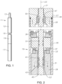
Fig. 1 is a schematic side view of an electrical submersible pump in accordance with this disclosure and installed in a well. -
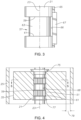
Fig. 2 is an axial sectional and partly schematic view of portions of the seal section of the electrical submersible pump ofFig. 1 . -
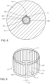
Fig. 3 is a side view of a portion of the shaft and key of the seal section ofFig. 2 , shown removed the seal section. -
Fig. 4 is an enlarged sectional view illustrating the thrust runner of the seal section ofFig. 2 . -
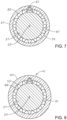
Fig. 5 is a sectional view of the thrust runner ofFig. 4 taken along the line 5 - 5 ofFig. 4 . -
Figs. 6 is a perspective view of the dampening spring shown inFig 5 between the shaft and the bore of the thrust runner, the dampening spring being removed from the shaft and thrust runner. -
Fig. 7 is a sectional view of a radial bearing in the seal section, taken along the line 7 - 7 ofFig. 3 and shown removed from the seal section. -
Fig. 8 is a sectional view of a screw pump in the seal section, taken along the line 8 - 8 ofFig. 2 and shown removed from the seal section. - The system of the present disclosure will now be described more fully hereinafter with reference to the accompanying drawings in which embodiments are shown. The system of the present disclosure may be in many different forms and should not be construed as limited to the illustrated embodiments set forth herein; rather, these embodiments are provided so that this disclosure will be thorough and complete, and will fully convey its scope to those skilled in the art. Like numbers refer to like elements throughout. In an embodiment, usage of the term "about" includes +/- 5% of the cited magnitude. In an embodiment, usage of the term "substantially" includes +/- 5% of the cited magnitude. The terms "upper" and "lower" and the like bare used only for convenience as the well pump may operate in positions other than vertical, including in horizontal sections of a well.
- It is to be further understood that the scope of the present disclosure is not limited to the exact details of construction, operation, exact materials, or embodiments shown and described, as modifications and equivalents will be apparent to one skilled in the art. In the drawings and specification, there have been disclosed illustrative embodiments and, although specific terms are employed, they are used in a generic and descriptive sense only and not for the purpose of limitation.
- However, the scope of the invention is defined by the appended claims.
- Referring to
Fig. 1 , an electrical well pump assembly (ESP) 11 of a type typically used for oil well pumping operations is illustrated. ESP 11 includes arotary pump 12 that may be a centrifugal pump having a large number of stages, each of the stages having an impeller and a diffuser.Pump 12 could also be a progressing cavity pump, which has a helical rotor that rotates within an elastomeric double helical stator.Pump 12 may be suspended in a well on a string ofproduction tubing 13.Pump 12 has anintake 15 and discharges intoproduction tubing 13. - ESP 11 also includes an
electrical motor 17 fordriving pump 12.Motor 17 connects topump 12 via aseal section 19, which has means for reducing a pressure differential between lubricant withinmotor 17 and the hydrostatic pressure of well fluid in the well.Intake 15 may be at the lower end ofpump 12, in the upper end ofseal section 19 or in a separate module. Also, ESP 11 may also include a gas separator, and if sointake 15 would be in the gas separator. - Referring to
Fig. 2 ,seal section 19 has ashaft 21 extending along alongitudinal axis 23 of acylindrical housing 25.Shaft 21 has a lower splined end (not shown) coupled to a shaft ofmotor 17 for rotatingshaft 21.Shaft 21 has an upper splined end (not shown) coupling to a shaft ofpump 12 fordriving pump 12. An upper guide orconnector 27 secures by threads tohousing 25 and has connecting features on its upper end (not shown) for connecting topump 12. A similar connector or guide (not shown) is on the lower end ofseal section 19 for connecting tomotor 17. -
Seal section 19 has a conventional pressure equalizer that is not shown but will normally comprise an elastomeric bag. Lubricant frommotor 17 communicates through passages inseal section 19 with the interior of the elastomeric bag. Well fluid is admitted into the chamber containing the elastomeric bag for imparting hydrostatic well fluid pressure on the elastomeric bag, which in turn applies the hydrostatic pressure to the motor lubricant.Seal section 19 also has a primary seal, normally a mechanical face seal, in an upper portion ofupper connector 27 for sealing well fluid from contact with the motor lubricant in the interior ofseal section 19. - The
seal section 19 has a thrust bearing assembly for transferring down thrust and up thrust imposed onshaft 21 frompump 12 tohousing 25.Seal section 19 could include a separate module for the thrust bearing assembly. The thrust bearing assembly may have various configurations and in this example has a non-rotating base including a downthrust transfer member 29 secured tohousing 25 for non-rotation relative tohousing 25.Thrust transfer member 29 may have ahelical passage 31 on its exterior to allow the flow of motor lubricant betweenthrust transfer member 29 andhousing 25. The base also includes a down thrust bearing 33 mounted on the upper side ofthrust transfer member 29 for non- rotation relative to thrusttransfer member 29. - A
thrust runner 35 is rigidly secured toshaft 21 abovethrust transfer member 29 for rotation in unison withshaft 21.Thrust runner 35 is a cylindrical member with bearingpads 37 on its lower side that slidingly engage down thrust bearing 33 to transfer down thrust.Thrust runner 35 also transfers any up thrust that may occur onshaft 21 to non-rotating upthrust pads 39.Thrust runner 35 has appreciable mass, being much larger in outer diameter thanshaft 21. It also has a significant axial dimension from its lower end to its upper end. - The thrust bearing assembly may also optionally have an inducer or screw
pump 41 for circulating motor lubricant. In this embodiment,screw pump 41 has ahelical flight 43 on its exterior that is in close reception with down thrust transfer member bore 45.Screw pump 41 is mounted toshaft 21 for rotation therewith. - In addition to a thrust bearing assembly,
seal section 19 also has radial bearing assemblies at the upper and lower ends ofhousing 25 for providing radial support toshaft 21.Fig. 2 shows only the top bearing assembly, but the bottom bearing assembly will have similar components. Those components include a bearingsleeve 47 that rotates withshaft 21. Bearingsleeve 47 has an outer diameter in sliding rotational engagement with anon-rotating bushing 49.Bushing 49 may be press fit intoconnector 27. Bearingsleeve 47 andbushing 49 may be of carbide material and are immersed in the motor lubricant withinseal section 19. -
Seal section 19 has one or more thrust runner tolerance rings or wave springs 51 (two shown) betweenshaft 21 and thrustrunner 35.Seal section 19 may also have one or more screw pump tolerance rings or wave springs 53 (two shown) betweenshaft 21 andscrew pump 41. In addition,seal section 19 may have a radial bearing tolerance ring orwave spring 55 betweenshaft 21 and bearingsleeve 47. The lower radial bearing (not shown) may also have a tolerance ring or wave spring. The various wave springs 51, 53 and 55 reduce vibration ofshaft 21, which might occur particularly at high rotational speeds. - Wave springs 51, 53 and 55 are located in annular recesses, and in this embodiment, all of the recesses are selectively located on
shaft 21.Fig. 3 shows a portion ofshaft 21 that has anannular recess 57 for receiving one of the shaft runner wave springs 51; the other recesses may be identical. Upper andlower shoulders annular recess 57.Upper shoulder 59 faces and may be parallel tolower shoulder 61. Upper andlower shoulders cylindrical surface 63 that has a smaller outer diameter than the outer diameter ofshaft 21. -
Shaft 21 also has a keyway groove orshaft slot 65 extending most of its length and parallel withaxis 23. In this embodiment,shaft slot 65 has a radial depth no greater than the radial width ofshoulders cylindrical surface 63.Shaft slot 65 does extend through upper andlower shoulders - A portion of a key 67 extends through
shaft slot 65 above and belowshoulders cylindrical surface 63.Key 67 has an inward facingside 66 that is illustrated as being spaced radially outward a slight distance from recesscylindrical surface 63, but it could touch recesscylindrical surface 63. The radial distance fromaxis 23 to key inward facingside 66 is not less than the radial distance fromaxis 23 to recesscylindrical surface 63 in this example. -
Fig. 5 , which is a transverse sectional view throughthrust runner 35, illustrates key 67 installed withinkeyway slot 65 and fitting within a mating keyway slot in runner bore 68 ofthrust runner 35.Key 67 imparts rotation ofshaft 21 to thrustrunner 35. The same key 67 may be used to impart rotation to screwpump 41 and bearing sleeve 47 (Fig. 2 ). Runner bore 68 does not have any recesses, rather has the same inner diameter from the upper side ofthrust runner 35 to the lower side ofthrust runner 35. -
Fig. 5 shows thrustrunner wave spring 51 installed in one of the thrust runner recesses 57 surrounded by thrust runner bore 68. Thrustrunner wave spring 51 is resilient and in frictional engagement with thrust runner bore 68 and with one of the thrust runner recesses 57. Thrustrunner way spring 51 is split, having two ends 69 that are separated from each other by a gap once installed inrecess 57. The gap between ends 69 is large enough for the passage ofkey 67, which causes thrustrunner wave spring 51 to rotate in unison withshaft 21. Thrustrunner wave spring 51 has outward protrudingindentations 71 that exert an outward bias force against thrust runner bore 68. Thrustrunner wave spring 51 has inward protrudingindentations 73 that exert an inward bias force against recesscylindrical surface 63. - Prior to installation, thrust
runner wave spring 51 has a radial or transverse width from its circumscribed outer diameter at outward protrudingindentations 71 to its circumscribed inner diameter at inward protrudingindentations 73 that is greater than the radial distance from recess cylindrical surface 63 (Fig. 3 ) to thrust runner bore 68. The resiliency of thrustrunner wave spring 51 and the split at ends 69 enable it to be resiliently expanded overshaft 21 and snapped intorecess 57. The resiliency also deflects the radial width of thrustrunner wave spring 51, causing it to fit tightly between recesscylindrical surface 63 and thrust runner bore 68. The deflection is elastic, less than the yield strength of the material of thrustrunner wave spring 51. - As shown in
Fig. 4 , eachwave spring 51 has an axial dimension that is only slightly less than the axial distance fromupper shoulder 59 tolower shoulder 61 and considerably less than the axial dimension ofthrust runner 35 from its lower end to its upper end.Fig. 4 also illustrates in exaggerated form an annular clearance that exists between the outer diameter ofshaft 21 and the inner diameter ofbore 68. A clearance is necessary in order to slidethrust runner 35 overshaft 21 during assembly, but it may be only a few thousandths of an inch. -
Thrust runner 35 is axially secured toshaft 21 so as to prevent any axial movement ofthrust runner 35 onshaft 21. In this example, a multi-pieceupper retainer 75 wedges betweenshaft 21 and thrust runner bore 68. Aretainer ring 77, which may be a snap ring, secures toshaft 21 at the lower end ofthrust runner 35. - Referring to
Figure 6 , thrustrunner wave spring 51 is formed of a metal, such as a spring steel. One example of a suitable metal is Hastelloy.Wave spring 51 is a curved strip that is formed into a partially cylindrical shape with an end gap 74 between its ends 69. After installation in thrust runner bore 68 (Fig. 5 ), end gap 74 is slightly greater than the width of key 67 (Fig. 5 ). In the example shown, thrustrunner wave spring 51 has a circumferentially extendingupper band 81 formed on its upper side and a circumferentially extendinglower band 83 formed on its lower side. - Outward-protruding waves or
indentations 71 are permanently formed in thrustrunner wave spring 51, creating convex shapes extending aroundwave spring 51. Outward-protrudingindentations 71 extend fromupper band 81 tolower band 83 and are parallel with axis 23 (Fig. 4 ). Eachindentation 71 is elongated, having a length greater than its width. Each inward-protruding wave orindentation 73 is located between two of the outward-protrudingindentation 71, creating concave shapes on the exterior of thrustrunner wave spring 51. Inward-protrudingindentations 73 are identical to outward-protrudingindentations 71 in length and width. Each inward-protrudingindentation 73 protrudes radially inward from upper andlower bands indentation 71. When viewed in cross-section, as inFig. 5 , outward and inward protrudingindentations - Referring to
Fig. 7 , topbearing wave spring 55 and its installation may be identical to thrust runner wave springs 51 and their installations. Topbearing wave spring 55 fits tightly between ashaft recess 85 and bearing sleeve bore 87 in the same manner as thrust runner wave springs 51.Key 67 engages mating slots inshaft 21 and bearing sleeve bore 87, causing bearingsleeve 47 and bearingsleeve wave spring 55 to rotate withshaft 21. The ends of bearingsleeve wave spring 55 are on opposite sides of key 67 in the same manner as described above. - Referring to
Fig. 8 , each screw pump wave spring 53 (two shown inFig. 2 ) and its installation may be identical to each thrustrunner wave spring 51 and its installation. Each fits tightly between ashaft recess 89 and screw pump bore 91 in the same manner as thrust runner wave springs 51.Key 67 engages mating slots inshaft 21 and screw pump bore 91, causingscrew pump 41 and screwpump wave spring 53 to rotate withshaft 21. The ends of screwpump wave spring 53 are on opposite sides of key 67 in the same manner as described above. - In operation,
motor 17 and portions ofseal section 19 are filled with a dielectric lubricant and assembled withpump 12 to form ESP 11. An operator runs ESP 11 into a well to pump well fluid. Supplying power to themotor 17 rotatesshaft 21. The various wave springs 51, 53 and 55 tend to reduce vibration ofshaft 21, particularly a high speeds. - The present invention described herein, therefore, is well adapted to carry out the objects and attain the ends and advantages mentioned, as well as others inherent therein. While only one embodiment of the invention has been given for purposes of disclosure, numerous changes exist in the details of procedures for accomplishing the desired results. These and other similar modifications will readily suggest themselves to those skilled in the art, and are intended to be encompassed within the scope of the invention which is defined by the following claims.
Claims (7)
- A submersible pump assembly (ESP) (11), comprising:a well fluid pump (12);a motor (17);a seal section (19) between the motor and the well fluid pump, the seal section comprising:a housing (25) having a longitudinal axis (23);a shaft (21) extending though the housing on the axis, the shaft being driven by the motor for driving the well fluid pump;a thrust bearing base (33) mounted in the housing for non-rotation relative to the housing;a thrust runner (35) having a runner bore (68) through which the shaft extends, the thrust runner having an outer diameter spaced radially inward from an inner surface of the housing by an annular clearance (79), the thrust runner being secured to the shaft to prevent axial movement of the thrust runner relative to the shaft, the thrust runner being in rotational, sliding engagement with an upper side of the thrust bearing base; characterized by:a thrust runner wave spring (51) that rotates in unison with the shaft and the thrust runner, the thrust runner wave spring being annular, metal and having an inner diameter surface (73) in contact with the shaft and an outer diameter surface (71) in contact with the runner bore;the thrust runner wave spring having a transverse width between the inner diameter surface and the outer diameter surface that is elastically deflectable, exerting an inward bias force against the shaft and an outward bias force against the runner bore to reduce radial vibration movement of the thrust runner;an annular thrust runner recess on the shaft, the thrust runner recess having an upper shoulder facing a lower shoulder and a recess cylindrical surface (63) between the upper and lower shoulders; and whereinthe thrust runner wave spring is located in the thrust runner recess with an inner diameter surface of the thrust runner wave spring in contact with the recess cylindrical surface;an axially extending shaft slot formed on the shaft that extends through the upper shoulder and the lower shoulder but not the recess cylindrical surface;an axially extending runner bore slot formed in the runner bore;a key that fits within both of the slots to cause rotation of the thrust runner in unison with the shaft, the key extending through the shoulders of the recess, the key having an inward facing surface (66) that is at a radial distance from the axis not less than a radial distance from the axis to the recess cylindrical surface; and whereinthe thrust runner wave spring has two ends spaced apart from each other by a gap through which the key extends.
- The ESP according to claim 1, further comprising:the annular thrust runner recess (57) on the shaft and the upper shoulder (59) facing the lower shoulder (61); and whereinthe thrust runner wave spring is located in the thrust runner recess and has an axial dimension less than a distance from the lower shoulder to the upper shoulder.
- The ESP according to claim 1, wherein:
The thrust runner wave spring comprises two of the thrust runner wave springs (51), each having an inner diameter surface in contact with the shaft and an outer diameter surface in contact with the runner bore. - The ESP according to claim 1, further comprising:a threaded connector (27) secured to one end of the housing for connecting one end of the seal section into the ESP, the connector having a connector bore through which the shaft extends;a bearing bushing(49) non-rotatably and rigidly mounted in the connector bore;a sleeve (47) mounted to the shaft for rotation therewith, the sleeve having an outer diameter in sliding engagement with the bearing bushing; andan annular, metal, bearing wave spring (55) having an inner diameter surface in contact with the shaft and an outer diameter surface in contact with the sleeve, the bearing wave spring being rotatable in unison with the shaft and the sleeve, the bearing wave spring having a radial width between the inner diameter surface and the outer diameter surface of the bearing wave spring that is elastically deflected between the shaft and the sleeve, exerting an inward bias force against the shaft and an outward bias force against the sleeve to reduce radial vibration movement of the shaft.
- The ESP according to claim 4 further comprising:an annular bearing recess (85) on the shaft; and whereinthe bearing wave spring is located in the bearing recess.
- The ESP according to claim 1, further comprising:a screw pump (41) having a screw pump bore (91) through which the shaft extends, the screw pump being mounted to the shaft for rotation therewith in the base bore (45) to pump motor lubricant through a base bore annulus between the shaft and the base bore; andan annular, metal, screw pump wave spring (53) having an inner diameter surface in contact with the shaft and an diameter surface in contact with the screw pump bore, the screw pump wave spring being rotatable in unison with the shaft and the screw pump, the screw pump wave spring having a radial width between the inner diameter surface and the outer diameter surface of the screw pump wave spring that is elastically deflected between the shaft and the base bore, exerting an inward bias force against the shaft and an outward bias force against the screw pump to reduce radial vibration movement of the shaft.
- The ESP according to claim 6, further comprising:a screw pump recess (89) on the shaft; and whereinthe screw pump wave spring is located in the screw pump recess.
Applications Claiming Priority (2)
| Application Number | Priority Date | Filing Date | Title |
|---|---|---|---|
| US16/410,080 US11248603B2 (en) | 2019-05-13 | 2019-05-13 | Thrust runner vibration dampening spring in electrical submersible pump |
| PCT/US2020/032573 WO2020232053A1 (en) | 2019-05-13 | 2020-05-13 | Thrust runner vibration dampening spring in electrical submersible pump |
Publications (3)
| Publication Number | Publication Date |
|---|---|
| EP3969723A1 EP3969723A1 (en) | 2022-03-23 |
| EP3969723A4 EP3969723A4 (en) | 2023-02-15 |
| EP3969723B1 true EP3969723B1 (en) | 2024-03-06 |
Family
ID=73231512
Family Applications (1)
| Application Number | Title | Priority Date | Filing Date |
|---|---|---|---|
| EP20805373.6A Active EP3969723B1 (en) | 2019-05-13 | 2020-05-13 | Thrust runner vibration dampening spring in electrical submersible pump |
Country Status (4)
| Country | Link |
|---|---|
| US (1) | US11248603B2 (en) |
| EP (1) | EP3969723B1 (en) |
| CA (1) | CA3140667C (en) |
| WO (1) | WO2020232053A1 (en) |
Families Citing this family (5)
| Publication number | Priority date | Publication date | Assignee | Title |
|---|---|---|---|---|
| JP6783820B2 (en) * | 2018-05-17 | 2020-11-11 | 本田技研工業株式会社 | Vibrating body unit |
| US11415138B2 (en) * | 2019-08-12 | 2022-08-16 | Baker Hughes Oilfield Operations, Llc | Intermediate bearing in electrical submersible pump |
| US12372102B2 (en) | 2022-04-29 | 2025-07-29 | Schlumberger Technology Corporation | System and method for vibration control |
| US12258950B2 (en) | 2023-01-12 | 2025-03-25 | Gd Energy Products, Llc | Open channel plunger for fracking pumps |
| US20250102040A1 (en) * | 2023-09-27 | 2025-03-27 | Halliburton Energy Services, Inc. | Spring assembly including two separate independent wave springs |
Family Cites Families (12)
| Publication number | Priority date | Publication date | Assignee | Title |
|---|---|---|---|---|
| US3936247A (en) * | 1973-08-15 | 1976-02-03 | Smith International, Inc. | Floating flow restrictors for fluid motors |
| US4222246A (en) * | 1978-12-11 | 1980-09-16 | Roller Bearing Company Of America | Slip clutch |
| DE69730781T2 (en) * | 1996-06-26 | 2005-09-29 | Rolls-Royce Corp., Indianapolis | Storage combination for a gas turbine |
| US8070426B2 (en) | 2008-05-19 | 2011-12-06 | Baker Hughes Incorporated | System, method and apparatus for open impeller and diffuser assembly for multi-stage submersible pump |
| US10598222B2 (en) * | 2012-01-03 | 2020-03-24 | New Way Machine Components, Inc. | Air bearing for use as seal |
| US9127683B2 (en) | 2012-11-02 | 2015-09-08 | Baker Hughes Incorporated | High temperature radial bearing for electrical submersible pump assembly |
| US10473106B2 (en) * | 2013-05-10 | 2019-11-12 | Halliburton Energy Services, Inc. | Apparatus and system for sealing submersible pump assemblies |
| US9334865B2 (en) | 2013-09-10 | 2016-05-10 | Baker Hughes Incorporated | Self-aligning and vibration damping bearings in a submersible well pump |
| DE102013110849B3 (en) * | 2013-10-01 | 2014-12-11 | Netzsch Pumpen & Systeme Gmbh | Submersible pump unit for use in a borehole |
| US9765790B2 (en) * | 2014-06-06 | 2017-09-19 | Baker Hughes Incorporated | Tandem thrust bearing with resilient bearing support |
| US9482282B2 (en) * | 2014-08-21 | 2016-11-01 | Zilift Holdings, Ltd. | Bearing for a rotary machine |
| US10371167B2 (en) | 2017-04-27 | 2019-08-06 | Baker Hughes, a GE company. LLC | Thrust bearing base for an electrical submersible well pump having an integrated heat exchanger |
-
2019
- 2019-05-13 US US16/410,080 patent/US11248603B2/en active Active
-
2020
- 2020-05-13 EP EP20805373.6A patent/EP3969723B1/en active Active
- 2020-05-13 WO PCT/US2020/032573 patent/WO2020232053A1/en not_active Ceased
- 2020-05-13 CA CA3140667A patent/CA3140667C/en active Active
Also Published As
| Publication number | Publication date |
|---|---|
| EP3969723A1 (en) | 2022-03-23 |
| EP3969723A4 (en) | 2023-02-15 |
| WO2020232053A1 (en) | 2020-11-19 |
| CA3140667A1 (en) | 2020-11-19 |
| US11248603B2 (en) | 2022-02-15 |
| CA3140667C (en) | 2023-10-10 |
| US20200362859A1 (en) | 2020-11-19 |
Similar Documents
| Publication | Publication Date | Title |
|---|---|---|
| CA3140667C (en) | Thrust runner vibration dampening spring in electrical submersible pump | |
| CA3146877C (en) | Intermediate bearing in electrical submersible pump | |
| US8651836B2 (en) | Torque transmitting rings for sleeves in electrical submersible pumps | |
| EP2914859B1 (en) | High temperature radial bearing for electrical submersible pump assembly | |
| US9334865B2 (en) | Self-aligning and vibration damping bearings in a submersible well pump | |
| CA2918462C (en) | Compliant abrasion resistant bearings for a submersible well pump | |
| US10344866B2 (en) | Seal assembly for abrasion resistant bearing of centrifugal pump | |
| EP4055252B1 (en) | Centralizing features in electrical submersible pump | |
| US9303648B2 (en) | Compliant radial bearing for electrical submersible pump | |
| WO2022204659A1 (en) | Interlocking diffuser arrangement in electrical submersible pump | |
| US20150071799A1 (en) | Self-Aligning and Vibration Damping Bearings in a Submersible Well Pump | |
| WO2020061227A1 (en) | Isolated chamber for mechanical face seal leakage in submersible well pump assembly | |
| GB2438522A (en) | A hydrostatic mechanical seal with local pressurization of seal interface | |
| US20240133376A1 (en) | Method and apparatus for an end seal for increasing efficiency of a submersible multistage labyrinth-screw pump | |
| CA3114800A1 (en) | Spring biased pump stage stack for submersible well pump assembly | |
| US20210238969A1 (en) | Motor Bearing With Anti-Rotation Spring For Electrical Submersible Well Pump |
Legal Events
| Date | Code | Title | Description |
|---|---|---|---|
| STAA | Information on the status of an ep patent application or granted ep patent |
Free format text: STATUS: THE INTERNATIONAL PUBLICATION HAS BEEN MADE |
|
| PUAI | Public reference made under article 153(3) epc to a published international application that has entered the european phase |
Free format text: ORIGINAL CODE: 0009012 |
|
| STAA | Information on the status of an ep patent application or granted ep patent |
Free format text: STATUS: REQUEST FOR EXAMINATION WAS MADE |
|
| 17P | Request for examination filed |
Effective date: 20211207 |
|
| AK | Designated contracting states |
Kind code of ref document: A1 Designated state(s): AL AT BE BG CH CY CZ DE DK EE ES FI FR GB GR HR HU IE IS IT LI LT LU LV MC MK MT NL NO PL PT RO RS SE SI SK SM TR |
|
| DAV | Request for validation of the european patent (deleted) | ||
| DAX | Request for extension of the european patent (deleted) | ||
| A4 | Supplementary search report drawn up and despatched |
Effective date: 20230113 |
|
| RIC1 | Information provided on ipc code assigned before grant |
Ipc: F04C 15/00 19680901ALI20230109BHEP Ipc: F04D 29/66 19680901ALI20230109BHEP Ipc: F04D 13/10 19680901ALI20230109BHEP Ipc: F04D 29/041 20060101ALI20230109BHEP Ipc: E21B 43/12 19680901AFI20230109BHEP |
|
| P01 | Opt-out of the competence of the unified patent court (upc) registered |
Effective date: 20230526 |
|
| GRAP | Despatch of communication of intention to grant a patent |
Free format text: ORIGINAL CODE: EPIDOSNIGR1 |
|
| STAA | Information on the status of an ep patent application or granted ep patent |
Free format text: STATUS: GRANT OF PATENT IS INTENDED |
|
| INTG | Intention to grant announced |
Effective date: 20231213 |
|
| RAP3 | Party data changed (applicant data changed or rights of an application transferred) |
Owner name: BAKER HUGHES OILFIELD OPERATIONS, LLC |
|
| GRAS | Grant fee paid |
Free format text: ORIGINAL CODE: EPIDOSNIGR3 |
|
| GRAA | (expected) grant |
Free format text: ORIGINAL CODE: 0009210 |
|
| STAA | Information on the status of an ep patent application or granted ep patent |
Free format text: STATUS: THE PATENT HAS BEEN GRANTED |
|
| AK | Designated contracting states |
Kind code of ref document: B1 Designated state(s): AL AT BE BG CH CY CZ DE DK EE ES FI FR GB GR HR HU IE IS IT LI LT LU LV MC MK MT NL NO PL PT RO RS SE SI SK SM TR |
|
| REG | Reference to a national code |
Ref country code: CH Ref legal event code: EP |
|
| REG | Reference to a national code |
Ref country code: IE Ref legal event code: FG4D |
|
| REG | Reference to a national code |
Ref country code: DE Ref legal event code: R096 Ref document number: 602020026934 Country of ref document: DE |
|
| REG | Reference to a national code |
Ref country code: LT Ref legal event code: MG9D |
|
| PG25 | Lapsed in a contracting state [announced via postgrant information from national office to epo] |
Ref country code: LT Free format text: LAPSE BECAUSE OF FAILURE TO SUBMIT A TRANSLATION OF THE DESCRIPTION OR TO PAY THE FEE WITHIN THE PRESCRIBED TIME-LIMIT Effective date: 20240306 |
|
| REG | Reference to a national code |
Ref country code: NL Ref legal event code: MP Effective date: 20240306 |
|
| PG25 | Lapsed in a contracting state [announced via postgrant information from national office to epo] |
Ref country code: GR Free format text: LAPSE BECAUSE OF FAILURE TO SUBMIT A TRANSLATION OF THE DESCRIPTION OR TO PAY THE FEE WITHIN THE PRESCRIBED TIME-LIMIT Effective date: 20240607 |
|
| PG25 | Lapsed in a contracting state [announced via postgrant information from national office to epo] |
Ref country code: HR Free format text: LAPSE BECAUSE OF FAILURE TO SUBMIT A TRANSLATION OF THE DESCRIPTION OR TO PAY THE FEE WITHIN THE PRESCRIBED TIME-LIMIT Effective date: 20240306 Ref country code: RS Free format text: LAPSE BECAUSE OF FAILURE TO SUBMIT A TRANSLATION OF THE DESCRIPTION OR TO PAY THE FEE WITHIN THE PRESCRIBED TIME-LIMIT Effective date: 20240606 |
|
| PG25 | Lapsed in a contracting state [announced via postgrant information from national office to epo] |
Ref country code: ES Free format text: LAPSE BECAUSE OF FAILURE TO SUBMIT A TRANSLATION OF THE DESCRIPTION OR TO PAY THE FEE WITHIN THE PRESCRIBED TIME-LIMIT Effective date: 20240306 |
|
| PG25 | Lapsed in a contracting state [announced via postgrant information from national office to epo] |
Ref country code: RS Free format text: LAPSE BECAUSE OF FAILURE TO SUBMIT A TRANSLATION OF THE DESCRIPTION OR TO PAY THE FEE WITHIN THE PRESCRIBED TIME-LIMIT Effective date: 20240606 Ref country code: LT Free format text: LAPSE BECAUSE OF FAILURE TO SUBMIT A TRANSLATION OF THE DESCRIPTION OR TO PAY THE FEE WITHIN THE PRESCRIBED TIME-LIMIT Effective date: 20240306 Ref country code: HR Free format text: LAPSE BECAUSE OF FAILURE TO SUBMIT A TRANSLATION OF THE DESCRIPTION OR TO PAY THE FEE WITHIN THE PRESCRIBED TIME-LIMIT Effective date: 20240306 Ref country code: GR Free format text: LAPSE BECAUSE OF FAILURE TO SUBMIT A TRANSLATION OF THE DESCRIPTION OR TO PAY THE FEE WITHIN THE PRESCRIBED TIME-LIMIT Effective date: 20240607 Ref country code: FI Free format text: LAPSE BECAUSE OF FAILURE TO SUBMIT A TRANSLATION OF THE DESCRIPTION OR TO PAY THE FEE WITHIN THE PRESCRIBED TIME-LIMIT Effective date: 20240306 Ref country code: ES Free format text: LAPSE BECAUSE OF FAILURE TO SUBMIT A TRANSLATION OF THE DESCRIPTION OR TO PAY THE FEE WITHIN THE PRESCRIBED TIME-LIMIT Effective date: 20240306 Ref country code: BG Free format text: LAPSE BECAUSE OF FAILURE TO SUBMIT A TRANSLATION OF THE DESCRIPTION OR TO PAY THE FEE WITHIN THE PRESCRIBED TIME-LIMIT Effective date: 20240306 |
|
| REG | Reference to a national code |
Ref country code: AT Ref legal event code: MK05 Ref document number: 1663701 Country of ref document: AT Kind code of ref document: T Effective date: 20240306 |
|
| PG25 | Lapsed in a contracting state [announced via postgrant information from national office to epo] |
Ref country code: SE Free format text: LAPSE BECAUSE OF FAILURE TO SUBMIT A TRANSLATION OF THE DESCRIPTION OR TO PAY THE FEE WITHIN THE PRESCRIBED TIME-LIMIT Effective date: 20240306 Ref country code: LV Free format text: LAPSE BECAUSE OF FAILURE TO SUBMIT A TRANSLATION OF THE DESCRIPTION OR TO PAY THE FEE WITHIN THE PRESCRIBED TIME-LIMIT Effective date: 20240306 |
|
| PG25 | Lapsed in a contracting state [announced via postgrant information from national office to epo] |
Ref country code: NL Free format text: LAPSE BECAUSE OF FAILURE TO SUBMIT A TRANSLATION OF THE DESCRIPTION OR TO PAY THE FEE WITHIN THE PRESCRIBED TIME-LIMIT Effective date: 20240306 |
|
| PG25 | Lapsed in a contracting state [announced via postgrant information from national office to epo] |
Ref country code: NL Free format text: LAPSE BECAUSE OF FAILURE TO SUBMIT A TRANSLATION OF THE DESCRIPTION OR TO PAY THE FEE WITHIN THE PRESCRIBED TIME-LIMIT Effective date: 20240306 |
|
| PG25 | Lapsed in a contracting state [announced via postgrant information from national office to epo] |
Ref country code: IS Free format text: LAPSE BECAUSE OF FAILURE TO SUBMIT A TRANSLATION OF THE DESCRIPTION OR TO PAY THE FEE WITHIN THE PRESCRIBED TIME-LIMIT Effective date: 20240706 |
|
| PG25 | Lapsed in a contracting state [announced via postgrant information from national office to epo] |
Ref country code: SM Free format text: LAPSE BECAUSE OF FAILURE TO SUBMIT A TRANSLATION OF THE DESCRIPTION OR TO PAY THE FEE WITHIN THE PRESCRIBED TIME-LIMIT Effective date: 20240306 Ref country code: PT Free format text: LAPSE BECAUSE OF FAILURE TO SUBMIT A TRANSLATION OF THE DESCRIPTION OR TO PAY THE FEE WITHIN THE PRESCRIBED TIME-LIMIT Effective date: 20240708 |
|
| PG25 | Lapsed in a contracting state [announced via postgrant information from national office to epo] |
Ref country code: CZ Free format text: LAPSE BECAUSE OF FAILURE TO SUBMIT A TRANSLATION OF THE DESCRIPTION OR TO PAY THE FEE WITHIN THE PRESCRIBED TIME-LIMIT Effective date: 20240306 Ref country code: EE Free format text: LAPSE BECAUSE OF FAILURE TO SUBMIT A TRANSLATION OF THE DESCRIPTION OR TO PAY THE FEE WITHIN THE PRESCRIBED TIME-LIMIT Effective date: 20240306 |
|
| PG25 | Lapsed in a contracting state [announced via postgrant information from national office to epo] |
Ref country code: AT Free format text: LAPSE BECAUSE OF FAILURE TO SUBMIT A TRANSLATION OF THE DESCRIPTION OR TO PAY THE FEE WITHIN THE PRESCRIBED TIME-LIMIT Effective date: 20240306 |
|
| PG25 | Lapsed in a contracting state [announced via postgrant information from national office to epo] |
Ref country code: PL Free format text: LAPSE BECAUSE OF FAILURE TO SUBMIT A TRANSLATION OF THE DESCRIPTION OR TO PAY THE FEE WITHIN THE PRESCRIBED TIME-LIMIT Effective date: 20240306 |
|
| PG25 | Lapsed in a contracting state [announced via postgrant information from national office to epo] |
Ref country code: SK Free format text: LAPSE BECAUSE OF FAILURE TO SUBMIT A TRANSLATION OF THE DESCRIPTION OR TO PAY THE FEE WITHIN THE PRESCRIBED TIME-LIMIT Effective date: 20240306 |
|
| PG25 | Lapsed in a contracting state [announced via postgrant information from national office to epo] |
Ref country code: SM Free format text: LAPSE BECAUSE OF FAILURE TO SUBMIT A TRANSLATION OF THE DESCRIPTION OR TO PAY THE FEE WITHIN THE PRESCRIBED TIME-LIMIT Effective date: 20240306 Ref country code: SK Free format text: LAPSE BECAUSE OF FAILURE TO SUBMIT A TRANSLATION OF THE DESCRIPTION OR TO PAY THE FEE WITHIN THE PRESCRIBED TIME-LIMIT Effective date: 20240306 Ref country code: RO Free format text: LAPSE BECAUSE OF FAILURE TO SUBMIT A TRANSLATION OF THE DESCRIPTION OR TO PAY THE FEE WITHIN THE PRESCRIBED TIME-LIMIT Effective date: 20240306 Ref country code: PT Free format text: LAPSE BECAUSE OF FAILURE TO SUBMIT A TRANSLATION OF THE DESCRIPTION OR TO PAY THE FEE WITHIN THE PRESCRIBED TIME-LIMIT Effective date: 20240708 Ref country code: PL Free format text: LAPSE BECAUSE OF FAILURE TO SUBMIT A TRANSLATION OF THE DESCRIPTION OR TO PAY THE FEE WITHIN THE PRESCRIBED TIME-LIMIT Effective date: 20240306 Ref country code: IS Free format text: LAPSE BECAUSE OF FAILURE TO SUBMIT A TRANSLATION OF THE DESCRIPTION OR TO PAY THE FEE WITHIN THE PRESCRIBED TIME-LIMIT Effective date: 20240706 Ref country code: EE Free format text: LAPSE BECAUSE OF FAILURE TO SUBMIT A TRANSLATION OF THE DESCRIPTION OR TO PAY THE FEE WITHIN THE PRESCRIBED TIME-LIMIT Effective date: 20240306 Ref country code: CZ Free format text: LAPSE BECAUSE OF FAILURE TO SUBMIT A TRANSLATION OF THE DESCRIPTION OR TO PAY THE FEE WITHIN THE PRESCRIBED TIME-LIMIT Effective date: 20240306 Ref country code: AT Free format text: LAPSE BECAUSE OF FAILURE TO SUBMIT A TRANSLATION OF THE DESCRIPTION OR TO PAY THE FEE WITHIN THE PRESCRIBED TIME-LIMIT Effective date: 20240306 |
|
| REG | Reference to a national code |
Ref country code: DE Ref legal event code: R119 Ref document number: 602020026934 Country of ref document: DE |
|
| PG25 | Lapsed in a contracting state [announced via postgrant information from national office to epo] |
Ref country code: IT Free format text: LAPSE BECAUSE OF FAILURE TO SUBMIT A TRANSLATION OF THE DESCRIPTION OR TO PAY THE FEE WITHIN THE PRESCRIBED TIME-LIMIT Effective date: 20240306 |
|
| REG | Reference to a national code |
Ref country code: CH Ref legal event code: PL |
|
| PG25 | Lapsed in a contracting state [announced via postgrant information from national office to epo] |
Ref country code: IT Free format text: LAPSE BECAUSE OF FAILURE TO SUBMIT A TRANSLATION OF THE DESCRIPTION OR TO PAY THE FEE WITHIN THE PRESCRIBED TIME-LIMIT Effective date: 20240306 |
|
| PG25 | Lapsed in a contracting state [announced via postgrant information from national office to epo] |
Ref country code: MC Free format text: LAPSE BECAUSE OF FAILURE TO SUBMIT A TRANSLATION OF THE DESCRIPTION OR TO PAY THE FEE WITHIN THE PRESCRIBED TIME-LIMIT Effective date: 20240306 |
|
| PLBE | No opposition filed within time limit |
Free format text: ORIGINAL CODE: 0009261 |
|
| STAA | Information on the status of an ep patent application or granted ep patent |
Free format text: STATUS: NO OPPOSITION FILED WITHIN TIME LIMIT |
|
| PG25 | Lapsed in a contracting state [announced via postgrant information from national office to epo] |
Ref country code: DK Free format text: LAPSE BECAUSE OF FAILURE TO SUBMIT A TRANSLATION OF THE DESCRIPTION OR TO PAY THE FEE WITHIN THE PRESCRIBED TIME-LIMIT Effective date: 20240306 |
|
| PG25 | Lapsed in a contracting state [announced via postgrant information from national office to epo] |
Ref country code: LU Free format text: LAPSE BECAUSE OF NON-PAYMENT OF DUE FEES Effective date: 20240513 |
|
| PG25 | Lapsed in a contracting state [announced via postgrant information from national office to epo] |
Ref country code: MC Free format text: LAPSE BECAUSE OF FAILURE TO SUBMIT A TRANSLATION OF THE DESCRIPTION OR TO PAY THE FEE WITHIN THE PRESCRIBED TIME-LIMIT Effective date: 20240306 Ref country code: LU Free format text: LAPSE BECAUSE OF NON-PAYMENT OF DUE FEES Effective date: 20240513 Ref country code: DK Free format text: LAPSE BECAUSE OF FAILURE TO SUBMIT A TRANSLATION OF THE DESCRIPTION OR TO PAY THE FEE WITHIN THE PRESCRIBED TIME-LIMIT Effective date: 20240306 Ref country code: CH Free format text: LAPSE BECAUSE OF NON-PAYMENT OF DUE FEES Effective date: 20240531 |
|
| 26N | No opposition filed |
Effective date: 20241209 |
|
| REG | Reference to a national code |
Ref country code: BE Ref legal event code: MM Effective date: 20240531 |
|
| PG25 | Lapsed in a contracting state [announced via postgrant information from national office to epo] |
Ref country code: DE Free format text: LAPSE BECAUSE OF NON-PAYMENT OF DUE FEES Effective date: 20241203 |
|
| PG25 | Lapsed in a contracting state [announced via postgrant information from national office to epo] |
Ref country code: IE Free format text: LAPSE BECAUSE OF NON-PAYMENT OF DUE FEES Effective date: 20240513 |
|
| PG25 | Lapsed in a contracting state [announced via postgrant information from national office to epo] |
Ref country code: SI Free format text: LAPSE BECAUSE OF FAILURE TO SUBMIT A TRANSLATION OF THE DESCRIPTION OR TO PAY THE FEE WITHIN THE PRESCRIBED TIME-LIMIT Effective date: 20240306 Ref country code: BE Free format text: LAPSE BECAUSE OF NON-PAYMENT OF DUE FEES Effective date: 20240531 |
|
| PG25 | Lapsed in a contracting state [announced via postgrant information from national office to epo] |
Ref country code: FR Free format text: LAPSE BECAUSE OF NON-PAYMENT OF DUE FEES Effective date: 20240531 |
|
| PG25 | Lapsed in a contracting state [announced via postgrant information from national office to epo] |
Ref country code: CY Free format text: LAPSE BECAUSE OF FAILURE TO SUBMIT A TRANSLATION OF THE DESCRIPTION OR TO PAY THE FEE WITHIN THE PRESCRIBED TIME-LIMIT; INVALID AB INITIO Effective date: 20200513 |
|
| PG25 | Lapsed in a contracting state [announced via postgrant information from national office to epo] |
Ref country code: HU Free format text: LAPSE BECAUSE OF FAILURE TO SUBMIT A TRANSLATION OF THE DESCRIPTION OR TO PAY THE FEE WITHIN THE PRESCRIBED TIME-LIMIT; INVALID AB INITIO Effective date: 20200513 |
|
| PG25 | Lapsed in a contracting state [announced via postgrant information from national office to epo] |
Ref country code: TR Free format text: LAPSE BECAUSE OF FAILURE TO SUBMIT A TRANSLATION OF THE DESCRIPTION OR TO PAY THE FEE WITHIN THE PRESCRIBED TIME-LIMIT Effective date: 20240306 |
|
| PGFP | Annual fee paid to national office [announced via postgrant information from national office to epo] |
Ref country code: GB Payment date: 20260421 Year of fee payment: 7 |
|
| PGFP | Annual fee paid to national office [announced via postgrant information from national office to epo] |
Ref country code: NO Payment date: 20260423 Year of fee payment: 7 |