EP3969659B1 - A method for producing cellulose products and a rotary forming mould system - Google Patents
A method for producing cellulose products and a rotary forming mould system Download PDFInfo
- Publication number
- EP3969659B1 EP3969659B1 EP20726387.2A EP20726387A EP3969659B1 EP 3969659 B1 EP3969659 B1 EP 3969659B1 EP 20726387 A EP20726387 A EP 20726387A EP 3969659 B1 EP3969659 B1 EP 3969659B1
- Authority
- EP
- European Patent Office
- Prior art keywords
- mould part
- forming
- mould
- cellulose
- pressure
- Prior art date
- Legal status (The legal status is an assumption and is not a legal conclusion. Google has not performed a legal analysis and makes no representation as to the accuracy of the status listed.)
- Active
Links
Images



Classifications
-
- D—TEXTILES; PAPER
- D21—PAPER-MAKING; PRODUCTION OF CELLULOSE
- D21J—FIBREBOARD; MANUFACTURE OF ARTICLES FROM CELLULOSIC FIBROUS SUSPENSIONS OR FROM PAPIER-MACHE
- D21J5/00—Manufacture of hollow articles by transferring sheets, produced from fibres suspensions or papier-mâché by suction on wire-net moulds, to couch-moulds
-
- B—PERFORMING OPERATIONS; TRANSPORTING
- B29—WORKING OF PLASTICS; WORKING OF SUBSTANCES IN A PLASTIC STATE IN GENERAL
- B29C—SHAPING OR JOINING OF PLASTICS; SHAPING OF MATERIAL IN A PLASTIC STATE, NOT OTHERWISE PROVIDED FOR; AFTER-TREATMENT OF THE SHAPED PRODUCTS, e.g. REPAIRING
- B29C43/00—Compression moulding, i.e. applying external pressure to flow the moulding material; Apparatus therefor
- B29C43/02—Compression moulding, i.e. applying external pressure to flow the moulding material; Apparatus therefor of articles of definite length, i.e. discrete articles
- B29C43/04—Compression moulding, i.e. applying external pressure to flow the moulding material; Apparatus therefor of articles of definite length, i.e. discrete articles using movable moulds
- B29C43/06—Compression moulding, i.e. applying external pressure to flow the moulding material; Apparatus therefor of articles of definite length, i.e. discrete articles using movable moulds continuously movable in one direction, e.g. mounted on chains, belts
- B29C43/08—Compression moulding, i.e. applying external pressure to flow the moulding material; Apparatus therefor of articles of definite length, i.e. discrete articles using movable moulds continuously movable in one direction, e.g. mounted on chains, belts with circular movement, e.g. mounted on rolls, turntables
-
- B—PERFORMING OPERATIONS; TRANSPORTING
- B26—HAND CUTTING TOOLS; CUTTING; SEVERING
- B26F—PERFORATING; PUNCHING; CUTTING-OUT; STAMPING-OUT; SEVERING BY MEANS OTHER THAN CUTTING
- B26F1/00—Perforating; Punching; Cutting-out; Stamping-out; Apparatus therefor
- B26F1/38—Cutting-out; Stamping-out
-
- B—PERFORMING OPERATIONS; TRANSPORTING
- B26—HAND CUTTING TOOLS; CUTTING; SEVERING
- B26F—PERFORATING; PUNCHING; CUTTING-OUT; STAMPING-OUT; SEVERING BY MEANS OTHER THAN CUTTING
- B26F1/00—Perforating; Punching; Cutting-out; Stamping-out; Apparatus therefor
- B26F1/38—Cutting-out; Stamping-out
- B26F1/384—Cutting-out; Stamping-out using rotating drums
-
- B—PERFORMING OPERATIONS; TRANSPORTING
- B29—WORKING OF PLASTICS; WORKING OF SUBSTANCES IN A PLASTIC STATE IN GENERAL
- B29C—SHAPING OR JOINING OF PLASTICS; SHAPING OF MATERIAL IN A PLASTIC STATE, NOT OTHERWISE PROVIDED FOR; AFTER-TREATMENT OF THE SHAPED PRODUCTS, e.g. REPAIRING
- B29C43/00—Compression moulding, i.e. applying external pressure to flow the moulding material; Apparatus therefor
- B29C43/02—Compression moulding, i.e. applying external pressure to flow the moulding material; Apparatus therefor of articles of definite length, i.e. discrete articles
-
- B—PERFORMING OPERATIONS; TRANSPORTING
- B29—WORKING OF PLASTICS; WORKING OF SUBSTANCES IN A PLASTIC STATE IN GENERAL
- B29C—SHAPING OR JOINING OF PLASTICS; SHAPING OF MATERIAL IN A PLASTIC STATE, NOT OTHERWISE PROVIDED FOR; AFTER-TREATMENT OF THE SHAPED PRODUCTS, e.g. REPAIRING
- B29C43/00—Compression moulding, i.e. applying external pressure to flow the moulding material; Apparatus therefor
- B29C43/32—Component parts, details or accessories; Auxiliary operations
- B29C43/44—Compression means for making articles of indefinite length
- B29C43/46—Rollers
-
- B—PERFORMING OPERATIONS; TRANSPORTING
- B29—WORKING OF PLASTICS; WORKING OF SUBSTANCES IN A PLASTIC STATE IN GENERAL
- B29C—SHAPING OR JOINING OF PLASTICS; SHAPING OF MATERIAL IN A PLASTIC STATE, NOT OTHERWISE PROVIDED FOR; AFTER-TREATMENT OF THE SHAPED PRODUCTS, e.g. REPAIRING
- B29C43/00—Compression moulding, i.e. applying external pressure to flow the moulding material; Apparatus therefor
- B29C43/32—Component parts, details or accessories; Auxiliary operations
- B29C43/52—Heating or cooling
-
- B—PERFORMING OPERATIONS; TRANSPORTING
- B29—WORKING OF PLASTICS; WORKING OF SUBSTANCES IN A PLASTIC STATE IN GENERAL
- B29C—SHAPING OR JOINING OF PLASTICS; SHAPING OF MATERIAL IN A PLASTIC STATE, NOT OTHERWISE PROVIDED FOR; AFTER-TREATMENT OF THE SHAPED PRODUCTS, e.g. REPAIRING
- B29C51/00—Shaping by thermoforming, i.e. shaping sheets or sheet like preforms after heating, e.g. shaping sheets in matched moulds or by deep-drawing; Apparatus therefor
- B29C51/26—Component parts, details or accessories; Auxiliary operations
- B29C51/44—Removing or ejecting moulded articles
- B29C51/445—Removing or ejecting moulded articles from a support after moulding, e.g. by cutting
-
- B—PERFORMING OPERATIONS; TRANSPORTING
- B30—PRESSES
- B30B—PRESSES IN GENERAL
- B30B11/00—Presses specially adapted for forming shaped articles from material in particulate or plastic state, e.g. briquetting presses, tabletting presses
- B30B11/16—Presses specially adapted for forming shaped articles from material in particulate or plastic state, e.g. briquetting presses, tabletting presses using pocketed rollers, e.g. two co-operating pocketed rollers
-
- B—PERFORMING OPERATIONS; TRANSPORTING
- B31—MAKING ARTICLES OF PAPER, CARDBOARD OR MATERIAL WORKED IN A MANNER ANALOGOUS TO PAPER; WORKING PAPER, CARDBOARD OR MATERIAL WORKED IN A MANNER ANALOGOUS TO PAPER
- B31B—MAKING CONTAINERS OF PAPER, CARDBOARD OR MATERIAL WORKED IN A MANNER ANALOGOUS TO PAPER
- B31B50/00—Making rigid or semi-rigid containers, e.g. boxes or cartons
- B31B50/59—Shaping sheet material under pressure
-
- B—PERFORMING OPERATIONS; TRANSPORTING
- B31—MAKING ARTICLES OF PAPER, CARDBOARD OR MATERIAL WORKED IN A MANNER ANALOGOUS TO PAPER; WORKING PAPER, CARDBOARD OR MATERIAL WORKED IN A MANNER ANALOGOUS TO PAPER
- B31D—MAKING ARTICLES OF PAPER, CARDBOARD OR MATERIAL WORKED IN A MANNER ANALOGOUS TO PAPER, NOT PROVIDED FOR IN SUBCLASSES B31B OR B31C
- B31D5/00—Multiple-step processes for making three-dimensional [3D] articles
- B31D5/02—Multiple-step processes for making three-dimensional [3D] articles including pressing
-
- D—TEXTILES; PAPER
- D21—PAPER-MAKING; PRODUCTION OF CELLULOSE
- D21F—PAPER-MAKING MACHINES; METHODS OF PRODUCING PAPER THEREON
- D21F9/00—Complete machines for making continuous webs of paper
-
- B—PERFORMING OPERATIONS; TRANSPORTING
- B29—WORKING OF PLASTICS; WORKING OF SUBSTANCES IN A PLASTIC STATE IN GENERAL
- B29C—SHAPING OR JOINING OF PLASTICS; SHAPING OF MATERIAL IN A PLASTIC STATE, NOT OTHERWISE PROVIDED FOR; AFTER-TREATMENT OF THE SHAPED PRODUCTS, e.g. REPAIRING
- B29C43/00—Compression moulding, i.e. applying external pressure to flow the moulding material; Apparatus therefor
- B29C43/32—Component parts, details or accessories; Auxiliary operations
- B29C43/44—Compression means for making articles of indefinite length
- B29C43/46—Rollers
- B29C2043/461—Rollers the rollers having specific surface features
- B29C2043/465—Rollers the rollers having specific surface features having one or more cavities, e.g. for forming distinct products
-
- B—PERFORMING OPERATIONS; TRANSPORTING
- B29—WORKING OF PLASTICS; WORKING OF SUBSTANCES IN A PLASTIC STATE IN GENERAL
- B29C—SHAPING OR JOINING OF PLASTICS; SHAPING OF MATERIAL IN A PLASTIC STATE, NOT OTHERWISE PROVIDED FOR; AFTER-TREATMENT OF THE SHAPED PRODUCTS, e.g. REPAIRING
- B29C51/00—Shaping by thermoforming, i.e. shaping sheets or sheet like preforms after heating, e.g. shaping sheets in matched moulds or by deep-drawing; Apparatus therefor
- B29C51/002—Shaping by thermoforming, i.e. shaping sheets or sheet like preforms after heating, e.g. shaping sheets in matched moulds or by deep-drawing; Apparatus therefor characterised by the choice of material
-
- B—PERFORMING OPERATIONS; TRANSPORTING
- B29—WORKING OF PLASTICS; WORKING OF SUBSTANCES IN A PLASTIC STATE IN GENERAL
- B29C—SHAPING OR JOINING OF PLASTICS; SHAPING OF MATERIAL IN A PLASTIC STATE, NOT OTHERWISE PROVIDED FOR; AFTER-TREATMENT OF THE SHAPED PRODUCTS, e.g. REPAIRING
- B29C51/00—Shaping by thermoforming, i.e. shaping sheets or sheet like preforms after heating, e.g. shaping sheets in matched moulds or by deep-drawing; Apparatus therefor
- B29C51/10—Forming by pressure difference, e.g. vacuum
-
- B—PERFORMING OPERATIONS; TRANSPORTING
- B29—WORKING OF PLASTICS; WORKING OF SUBSTANCES IN A PLASTIC STATE IN GENERAL
- B29K—INDEXING SCHEME ASSOCIATED WITH SUBCLASSES B29B, B29C OR B29D, RELATING TO MOULDING MATERIALS OR TO MATERIALS FOR MOULDS, REINFORCEMENTS, FILLERS OR PREFORMED PARTS, e.g. INSERTS
- B29K2001/00—Use of cellulose, modified cellulose or cellulose derivatives, e.g. viscose, as moulding material
-
- B—PERFORMING OPERATIONS; TRANSPORTING
- B29—WORKING OF PLASTICS; WORKING OF SUBSTANCES IN A PLASTIC STATE IN GENERAL
- B29L—INDEXING SCHEME ASSOCIATED WITH SUBCLASS B29C, RELATING TO PARTICULAR ARTICLES
- B29L2031/00—Other particular articles
- B29L2031/28—Tools, e.g. cutlery
- B29L2031/286—Cutlery
Definitions
- the present disclosure relates to a method for producing cellulose products from an air-formed cellulose blank structure in a rotary forming mould system.
- the disclosure further relates to a rotary forming mould system.
- WO 2017/160218 A1 discloses a prior art method and system for producing discrete three-dimensional cellulose products from an air-formed cellulose blank structure in a forming mould.
- Cellulose fibres are often used as raw material for producing or manufacturing products. Products formed of cellulose fibres can be used in many different situations where there is a need for having sustainable products. A wide range of products can be produced from cellulose fibres and a few examples are disposable plates and cups, blank structures and packaging materials.
- Forming moulds are commonly used when manufacturing cellulose products from raw materials including cellulose fibres, and traditionally the cellulose products have been produced with wet-forming techniques.
- a material commonly used for cellulose fibre products is wet moulded pulp.
- Wet moulded pulp has the advantage of being considered as a sustainable packaging material, since it is produced from biomaterials and can be recycled after use. Consequently, wet moulded pulp has been quickly increasing in popularity for different applications.
- Wet moulded pulp articles are generally formed by immersing a suction forming mould into a liquid or semi liquid pulp suspension or slurry comprising cellulose fibres, and when suction is applied, a body of pulp is formed with the shape of the desired product by fibre deposition onto the forming mould.
- One development in the field of producing cellulose products is the forming of cellulose fibres without using wet-forming techniques. Instead of forming the cellulose products from a liquid or semi liquid pulp suspension or slurry, an air-formed cellulose blank is used. The air-formed cellulose blank is inserted into a forming mould and during the forming of the cellulose products the cellulose blank is subjected to a high forming pressure and a high forming temperature.
- the forming systems used for forming cellulose products from air-formed cellulose blank structures are limited in production capacity, since the forming of the cellulose products take place in forming systems with relatively long cycle times.
- the high pressure needed when forming the cellulose products is limiting the number of products that can be formed in a single pressure forming step.
- An object of the present disclosure is to provide a method for producing cellulose products from an air-formed cellulose blank structure and a rotary forming mould system where the previously mentioned problems are avoided. This object is at least partly achieved by the features of the independent claims.
- the dependent claims contain further developments of the method for producing cellulose products and the rotary forming mould system.
- the disclosure concerns a method for producing discrete three-dimensional cellulose products from an air-formed cellulose blank structure in a rotary forming mould system.
- the rotary forming mould system comprises at least one first mould part and at least one second mould part, where the at least one first mould part and the at least one second mould part are rotatably arranged in relation to each other. During rotational movements the at least one first mould part is rotatably interacting with the at least one second mould part.
- the method comprises the steps; providing the air-formed cellulose blank structure, wherein the cellulose blank structure is air-formed from cellulose fibres; transporting the air-formed cellulose blank structure to the rotary forming mould system; feeding the air-formed cellulose blank structure to a position between a first mould part and a second mould part, and heating the air-formed cellulose blank structure to a forming temperature in the range of 100°C to 300°C; forming the three-dimensional cellulose products from the air-formed cellulose blank structure in the rotary forming mould system, by pressing the heated air-formed cellulose blank structure with a forming pressure of at least 1 MPa, preferably 4-20 MPa, between the first mould part and the second mould part, where during forming the first mould part is rotating around a first rotational axis and the second mould part is rotating around a second rotational axis.
- the forming of the discrete three-dimensional cellulose products from the air-formed cellulose blank structure can be made with an increased production speed, since the rotational movements of the mould parts are reducing the cycle times compared to traditional forming methods.
- the reciprocating movement establishing the high pressure needed when forming the cellulose products is limiting the number of products that can be formed in a single pressure forming step, and the rotary forming of cellulose products is providing a way to overcome this problem since no mass has to be accelerated and single products can be produced with high speed in continuous rotating movements.
- discrete cellulose products is meant that individual or separated products are formed in the process, which is different from the forming of continuous structures, such as webs or sheets of cellulose material.
- the formed discrete cellulose products are having a three-dimensional shape, which is different from flat or two-dimensional shapes.
- three-dimensional products according to the disclosure are disposable cutlery, plates, cups and bowls; three-dimensional packaging structures or packaging inserts; coffee pods; coat-hangers; and meat trays.
- the air-formed cellulose blank structure has a dry basis weight in the range of 200-3000 g/m 2 , preferably 300-3000 g/m 2 , and more preferably 400-3000 g/m 2 .
- the air-formed cellulose blank structure with these properties are suitable for the forming of the three-dimensional cellulose products.
- the cellulose blank structure is a relatively thick and fluffy structure compared to traditional wet-laid paper or tissue structures.
- the bulky cellulose blank structure is compacted during the forming process, and the cellulose fibres in the three-dimensional cellulose products are strongly bonded to each other with hydrogen bonds, providing a stiff compacted three-dimensional product structure.
- the forming pressure is applied to the air-formed cellulose blank structure in a pressure-forming zone established between the first mould part and the second mould part.
- the pressure-forming zone is formed as a gap and/or force section between the first mould part and the second mould part established during rotational movements of the first mould part and the second mould part in relation to each other.
- the pressure-forming zone has an extension between the first mould part and the second mould part where the first mould part and/or the second mould part are exerting pressure on the air-formed cellulose blank structure during forming of the three-dimensional cellulose products.
- the pressure-forming zone is thus a zone formed between the first mould part and the second mould part during the rotational movements of the interacting mould parts.
- the pressure-forming zone has a non-linear configuration in a plane parallel to and extending through the first rotational axis and the second rotational axis at least partly along a first peripheral length of the first mould part and a second peripheral length of the second mould part during rotational movements of the first mould part and the second mould part.
- the non-linear configuration in the plane is providing three-dimensionally shaped products.
- the method further comprises the step; exerting a highest instantaneous forming pressure on the air-formed cellulose blank structure in a plane parallel to and extending through the first rotational axis and the second rotational axis during rotational movements of the first mould part and the second mould part.
- the highest instantaneous forming pressure is the highest pressure level exerted on the air-formed cellulose blank structure during the rotary forming of the three-dimensional cellulose products when using for example mould parts with high stiffness.
- the first mould part and/or the second mould part comprises a deformation element arranged to exert the forming pressure on the air-formed cellulose blank structure during forming of the three-dimensional cellulose products.
- the deformation element is used for evening out the pressure distribution in the forming mould for an efficient forming of the three-dimensional cellulose products.
- the pressure-forming zone is arranged as a closed volume between the first mould part and the second mould part during forming of the three-dimensional cellulose products.
- the closed volume is securing an efficient forming when using the deformation element and enables more steep deep drawing angles in different directions of the three-dimensional cellulose products.
- the forming pressure is an isostatic forming pressure of at least 1 MPa, preferably 4-20 MPa.
- the isostatic forming pressure is providing an efficient forming of the three-dimensional cellulose products, for example, when the products have complex three-dimensional shapes.
- the method further comprises the step; feeding the air-formed cellulose blank structure during forming of the three-dimensional cellulose products between the first mould part and the second mould part with a transportation speed corresponding to the rotational speed of the first mould part and the rotational speed of the second mould part in the pressure-forming zone.
- the transportation speed corresponding to the rotational speeds of the mould parts is securing an efficient feeding of the air-formed cellulose blank structure with minimized risks for rupturing the air-formed cellulose blank structure.
- the first rotational axis and the second rotational axis are arranged in a parallel relationship to each other. With this relationship between the rotational axes, a compact design of the rotary forming mould system can be achieved.
- the method further comprises the steps; rotating the first mould part around the first rotational axis in a first rotational direction; and rotating the second mould part around the second rotational axis in a second rotational direction, where the first rotational direction is opposite the second rotational direction, or where the first rotational direction is the same as the second rotational direction.
- the mould parts can interact in an efficient way when forming the three-dimensional cellulose products.
- the rotary forming mould system can be constructed with a compact design.
- the first mould part comprises a first cutting edge
- the second mould part comprises a second cutting edge.
- the first cutting edge is configured to interact with the second cutting edge, or during rotational movements of the first mould part and the second mould part the first cutting edge is configured to interact with the second mould part, or during rotational movements of the first mould part and the second mould part the second cutting edge is configured to interact with the first mould part.
- the cutting edges are arranged for removing unwanted residual cellulose fibres from the air-formed cellulose blank structure. The cut residual cellulose fibres may be reused for air-forming cellulose blank structures if desired.
- the disclosure further concerns a rotary forming mould system arranged for forming discrete three-dimensional cellulose products from an air-formed cellulose blank structure.
- the rotary forming mould system comprises at least one first mould part and at least one second mould part, where the at least one first mould part and the at least one second mould part are rotatably arranged in relation to each other. During rotational movements, the at least one first mould part is rotatably interacting with the at least one second mould part.
- the rotary forming mould system is configured to heating the air-formed cellulose blank structure to a forming temperature in the range of 100°C to 300°C, and configured to forming the three-dimensional cellulose products from the air-formed cellulose blank structure in the rotary forming mould system, by pressing the heated air-formed cellulose blank structure with a forming pressure P F of at least 1 MPa, preferably 4-20 MPa, between the first mould part and the second mould part, where during forming the first mould part is arranged to rotate around a first rotational axis and the second mould part is arranged to rotate around a second rotational axis.
- the forming of the three-dimensional cellulose products from the air-formed cellulose blank structure can be made with an increased production speed in the rotary forming mould system, since the rotational movements of the mould parts are reducing the cycle times compared to traditional forming methods.
- the air-formed cellulose blank structure has a dry basis weight in the range of 200-3000 g/m 2 , preferably 300-3000 g/m 2 , and more preferably 400-3000 g/m 2 , providing suitable properties of the air-formed cellulose blank structure for forming in the forming mould system.
- the rotary forming mould system further comprises a first base structure and a second base structure.
- the at least one first mould part is arranged on the first base structure, and the at least one second mould part is arranged on the second base structure.
- the first base structure and the second base structure are rotatably arranged in relation to each other.
- the base structures are arranged for holding the mould parts during the rotary forming process.
- the forming pressure is applied in a pressure-forming zone established between the first mould part and the second mould part.
- the pressure-forming zone is configured as a gap and/or force section between the first mould part and the second mould part established during rotational movements of the first mould part and the second mould part in relation to each other.
- the pressure-forming zone has an extension between the first mould part and the second mould part where the first mould part and/or the second mould part are exerting pressure on the air-formed cellulose blank structure during forming of the three-dimensional cellulose products.
- the pressure-forming zone is configured with a non-linear shape in a plane parallel to and extending through the first rotational axis and the second rotational axis at least partly along a first peripheral length of the first mould part and a second peripheral length of the second mould part during rotational movements of the first mould part and the second mould part.
- the first rotational axis and the second rotational axis are arranged in a parallel relationship to each other.
- the first mould part and the second mould part during are rotational movements configured to exerting a highest instantaneous forming pressure on the air-formed cellulose blank structure in a plane parallel to and extending through the first rotational axis and the second rotational axis.
- the highest instantaneous forming pressure is the highest pressure level exerted on the air-formed cellulose blank structure during the rotary forming of the three-dimensional cellulose products when using for example mould parts with high stiffness.
- the first mould part and/or the second mould part comprises a deformation element configured to exerting the forming pressure on the air-formed cellulose blank structure during forming of the three-dimensional cellulose products.
- the deformation element is used for evening out the pressure distribution in the forming mould for an efficient forming of the three-dimensional cellulose products.
- the pressure-forming zone is arranged as a closed volume between the first mould part and the second mould part during forming of the three-dimensional cellulose products.
- the closed volume is securing an efficient forming when using the deformation element.
- the forming pressure is an isostatic forming pressure of at least 1 MPa, preferably 4-20 MPa.
- the first mould part is configured for rotating around the first rotational axis in a first rotational direction
- the second mould part is configured for rotating around the second rotational axis in a second rotational direction.
- the first rotational direction is opposite the second rotational direction, or the first rotational direction is the same as the second rotational direction.
- the first mould part is configured to be removably attached to the first base structure and/or the second mould part is configured to be removably attached to the second base structure.
- the base structures can thus be used for different types of mould parts.
- the first mould part comprises a first cutting edge
- the second mould part comprises a second cutting edge.
- the first cutting edge is configured to interact with the second cutting edge, or during rotational movements of the first mould part and the second mould part the first cutting edge is configured to interact with the second mould part, or during rotational movements of the first mould part and the second mould part the second cutting edge is configured to interact with the first mould part.
- the cutting edges are arranged for removing unwanted residual cellulose fibres from the air-formed cellulose blank structure, and the cut residual cellulose fibres may be reused for air-forming cellulose blank structures if desired.
- a rotary forming mould system 3 for producing discrete three-dimensional cellulose products 1 from an air-formed cellulose blank structure 2 is schematically shown.
- the cellulose blank structure 2 may be a pre-formed structure comprising cellulose fibres, where the cellulose fibres are carried and formed to the fibre blank structure 2 by air as carrying medium in an air-forming process.
- discrete cellulose products With discrete cellulose products is meant that individual or separated products are formed in the process, which is different from the forming of continuous structures, such as webs or sheets of cellulose material.
- the formed discrete cellulose products are having a three-dimensional shape, which is different from flat or two-dimensional shapes.
- Cellulose structures such as airlaid webs, tissue webs, boards and other flat cellulose fibre webs are defined as two-dimensional structures, which are different from the discrete three-dimensional cellulose products according to the disclosure.
- the flat structures are defined as two-dimensional even if they are provided with embossed surfaces or other surface structures.
- Examples of three-dimensional products according to the disclosure are disposable cutlery, plates, cups and bowls; three-dimensional packaging structures or packaging inserts; coffee pods; coat-hangers; and meat trays. Any type of cellulose product having a well-defined extension in three dimensions may be produced with the method and system according to the disclosure.
- a cellulose blank structure 2 is meant a fibre web structure produced from cellulose fibres.
- air-forming of the cellulose blank structure 2 is meant the formation of a cellulose blank structure in a dry-forming process in which cellulose fibres are air-formed to produce the cellulose blank structure 2.
- the cellulose fibres are carried and formed to the fibre blank structure 2 by air as carrying medium. This is different from a normal papermaking process or a traditional wet-forming process, where water is used as carrying medium for the cellulose fibres when forming the paper or fibre structure.
- the cellulose blank structure 2 may have a dryness that is mainly corresponding to the ambient humidity in the atmosphere surrounding the dry-formed cellulose blank structure 2.
- the dryness of the cellulose blank structure 2 may be controlled in order to have a suitable dryness level when forming the cellulose products 1.
- the cellulose blank structure 2 may be formed of cellulose fibres in a conventional dry-forming process and be configured in different ways.
- the cellulose blank structure 2 may have a composition where the fibres are of the same origin or alternatively contain a mix of two or more types of cellulose fibres, depending on the desired properties of the cellulose products 1.
- the cellulose fibres used in the cellulose blank structure 2 are during the forming of the cellulose products 1 strongly bonded to each other with hydrogen bonds.
- the cellulose fibres may be mixed with other substances or compounds to a certain amount as will be further described below.
- cellulose fibres is meant any type of cellulose fibres, such as natural cellulose fibres or manufactured cellulose fibres.
- the cellulose blank structure 2 may have a single-layer or a multi-layer configuration.
- a cellulose blank structure 2 having a single-layer configuration is referring to a cellulose blank structure that is formed of one layer containing cellulose fibres.
- a cellulose blank structure 2 having a multi-layer configuration is referring to a cellulose blank structure that is formed of two or more layers containing cellulose fibres, where the layers may have the same or different compositions or configurations.
- An additional layer comprising cellulose fibres may be arranged as a carrying layer for the cellulose blank structure 2, and the additional layer may have a higher tensile strength than the cellulose blank structure 2.
- the additional layer with a higher tensile strength acts in this way as a supporting structure for the cellulose blank structure 2.
- the additional layer may for example be a tissue layer containing cellulose fibres, an airlaid structure comprising cellulose fibres, or other suitable layer structures.
- the air-formed cellulose blank structure 2 has suitably a dry basis weight in the range of 200-3000 g/m 2 , preferably 300-3000 g/m 2 , and more preferably 400-3000 g/m 2 .
- the dry basis weight values described are web-average values, and test have shown that these web-average values are suitable when forming the cellulose products 1.
- the cellulose blank structure 2 is a relatively thick and fluffy structure compared to traditional wet-laid paper or tissue structures.
- tests have shown that the density of the cellulose blank structure 2 when arranged in the forming mould system 3 may be lower than 100 kg/m 3 , which is providing a bulky structure suitable for forming in the forming mould system 3.
- the density is depending on the dry-forming process and grade of pre-compression of the cellulose blank structure 2 before the forming of the cellulose products 1 in the forming mould system 3.
- a pressure of 0.5 kPa is applied to a sample piece of the cellulose blank structure 2.
- the measured thickness of the cellulose blank structure 2 under load together with the basis weight is used for determining the density.
- the cellulose blank structure 2 is compacted during the forming process, and the cellulose fibres in the three-dimensional cellulose products 1 are strongly bonded to each other with hydrogen bonds, providing a stiff compacted three-dimensional product structure.
- the rotary forming mould system 3 comprises at least one first mould part 5a and at least one second mould part 5b.
- the at least one first mould part 5a and the at least one second mould part 5b are rotatably arranged in relation to each other, and arranged as discrete mould parts that are interacting with each other during the forming of the three-dimensional cellulose products 1.
- the at least one first mould part 5a is rotatably interacting with at least one corresponding second mould part 5b for forming the three-dimensional cellulose products 1, and the mould parts are adapted to move in relation to each other for establishing a desired shape of the cellulose products 2 produced in the rotary forming mould system 3.
- Each first mould part 5a is interacting with a corresponding second mould part 5b.
- the rotary forming mould system 3 further comprises a rotatably arranged first base structure 4a, and a rotatably arranged second base structure 4b.
- the least one first mould part 5a is arranged on the first base structure 4a, and the at least one second mould part 5b is arranged on the second base structure 4b.
- the first base structure 4a and the second base structure 4b each comprises a plurality of discrete first mould parts 5a and discrete second mould parts 5b respectively.
- the first base structure 4a and the second base structure 4b are rotatably arranged in relation to each other, and during rotational movements of the first base structure 4a and the second base structure 4b the first mould parts 5a are rotatably interacting with corresponding second mould parts 5b, as will be further described below.
- the first base structure 4a and the second base structure 4b may have any suitable structural configurations for holding the first and second mould parts respectively.
- the base structures may be formed as rotating constructions of steel or other suitable metals, composite materials, plastic materials or combinations of different materials.
- the first base structure 4a and the second base structure 4b are each driven by a suitable power source, such as electric motors.
- the first base structure 4a and the second base structure 4b are driven by the same electric motor through for example a belt drive, chain drive, or gear drive arrangement.
- the first mould parts 5a and the second mould parts 5b are attached to the respective base structures with suitable fastening means, such as for example bolts, screws, rivets, or other fastening elements, and the mould parts may be releasably attached for a simple removal of the mould parts when needed.
- suitable fastening means such as for example bolts, screws, rivets, or other fastening elements
- the mould parts may be releasably attached for a simple removal of the mould parts when needed.
- the at least one first mould part 5a may be configured to be removably attached to the first base structure 4a
- the at least one second mould part 5b may be configured to be removably attached to the second base structure 4b.
- the at least one first mould part 5a and/or the at least one second mould part 5b may suitably be movably arranged in relation to the respective base structures during forming of the cellulose products 1. Movably arranged mould parts may be used when the cellulose products are having complex three-dimensional shapes.
- the first mould parts 5a and the second mould parts 5b are arranged to interact with each other during the forming of the cellulose products 1, and are shaped to form the discrete three-dimensional cellulose products during the rotational movements of the first and second mould parts in relation to each other.
- the first mould parts 5a and the second mould parts 5b thus have mould shapes corresponding to the three-dimensional shape of the cellulose products to be produced.
- the first mould parts 5a may be shaped as male moulds and the second mould parts 5b may be shaped as corresponding female moulds, or alternatively the first mould parts 5a may be shaped as female moulds and the second mould parts 5b may be shaped as corresponding male moulds.
- the first mould parts 5a and the second mould parts 5b may each have both male and female mould sections, depending on the shape of the three-dimensional cellulose products 1 to be produced, as schematically illustrated in figure 2b , where a three-dimensional disposable cellulosic spoon is exemplified. Corresponding male and female mould sections of the respective mould parts are interacting with each other during the rotational movements of the mould parts. In this way, a three-dimensional shape of the cellulose products 1 is established between the mould parts.
- the first base structure 4a and the second base structure 4b may be formed as forming wheels having essentially circular peripheral shapes, and the first mould parts 5a and the second mould parts 5b are arranged on the outer peripheries of the respective base structures, as illustrated in figures 1a-b and 2a-b .
- the respective mould parts may have curved shapes to match the base structures, and the curved shapes are enabling the rotating interaction between the first mould parts 5a and the second mould parts 5b.
- the base structures may have other designs and configurations if desired.
- the first mould part 5a is configured for rotating around a first rotational axis A R1 in a first rotational direction D R1
- the second mould part 5b is configured for rotating around the second rotational axis A R2 in a second rotational direction D R2 .
- the first rotational direction D R1 is opposite the second rotational direction D R2 .
- the first rotational axis A R1 and the second rotational axis A R2 are suitably arranged in a parallel relationship to each other. If desired, the first rotational axis A R1 and the second rotational axis A R2 may instead be arranged in a non-parallel relationship to each other.
- a first axle structure 9a may be arranged for rotating the first base structure 4a and the first mould parts 5a around the first rotational axis A R1 in the first rotational direction D R1 .
- the first axle structure 9a may be attached to the first base structure 4a with suitable fastening means, and the first axle structure 9a may be journally attached to a frame structure or similar arrangement via suitable bearings.
- a second axle structure 9b may be arranged for rotating the second base structure 4b and the second mould parts 5b around the second rotational axis A R2 in the second rotational direction D R2 .
- the second axle structure 9b may be attached to the second base structure 4b with suitable fastening means, and the second axle structure 9a may be journally attached to the frame structure or similar arrangement via suitable bearings.
- the first mould parts 5a are rotatably interacting with corresponding second mould parts 5b.
- Each first mould part 5a on the first base structure 4a has a corresponding second mould part 5b on the second base structure 4b, where the corresponding mould parts are cooperating when forming the cellulose products 1.
- the first mould parts 5a meet and interact with the corresponding second mould parts 5b, and the cellulose products 1 are formed in a space formed between the first mould parts 5a and the second mould parts 5b.
- the rotary forming mould system 3 is configured to heating the cellulose blank structure 2 to a forming temperature in the range of 100°C to 300°C with suitable heating means.
- the cellulose blank structure 2 may for example be pre-heated in a heating unit, exposed to hot air or steam, or alternatively the mould parts may be heated.
- the rotary forming mould system 3 is further configured to forming the cellulose products 1 from the cellulose blank structure 2 in the rotary forming mould system 3, by pressing the heated cellulose blank structure 2 with a forming pressure P F of at least 1 MPa, preferably 4-20 MPa, between the first mould part 5a and the second mould part 5b.
- the forming temperature of the cellulose blank structure 2 may for example be measured with suitable temperature sensors when the cellulose blank structure 2 is formed between the mould parts, such as for example temperature sensors integrated in the mould parts, or thermochromic temperature sensors arranged in connection to or in the cellulose blank structure 2.
- suitable sensors may for example be IR sensors measuring the temperature of the cellulose blank structure 2 directly after forming between the mould parts.
- the forming pressure P F is applied to the cellulose blank structure 2 in the space formed between the first mould part 5a and the second mould part 5b. More specifically, the forming pressure P F is applied in a pressure-forming zone 6 established between the first mould part 5a and the second mould part 5b, where the pressure-forming zone 6 is configured as a gap and/or force section between the first mould part 5a and the second mould part 5b.
- the gap and/or force section is established during rotational movements of the first mould part 5a and the second mould part 5b in relation to each other. With a gap section is meant that a gap is established between the mould parts in the pressure-forming zone 6, where the cellulose products 1 are formed in the gap from the cellulose blank structure 2.
- the amount of supplied cellulose fibres into the gap determines the obtained forming pressure in the gap.
- the first rotational axis A R1 is with this configuration arranged at a fixed distance from the second rotational axis A R2 .
- a force section between the mould parts is referring to situations where there is no initial gap between the mould parts, and where a force F is exerted between the mould parts is used for forming the cellulose products, as schematically illustrated in figures 1a , 2a-b . This may be the case if the respective base structures 4a, 4b are spring-loaded and arranged to exert pressure onto the respective mould parts, wherein the mould parts are pressed in a direction towards each other during the forming process.
- the first rotational axis A R1 is with this configuration arranged to move in relation to the second rotational axis A R2 .
- a forming space is established between the mould parts when the cellulose blank structure 2 is arranged between the mould parts, since the mould parts through the spring-loaded configuration are allowed to move in relation to each other.
- the pressure-forming zone 6 is defined to have an extension between the first mould part 5a and the second mould part 5b where the first mould part 5a and/or the second mould part 5b are exerting pressure on the cellulose blank structure 2 during forming of the cellulose products 1.
- the pressure-forming zone 6 may vary for example depending on the type and design of mould parts used, the thickness and configuration of the cellulose blank structure 2, and the properties of the cellulose fibres in the cellulose blank structure 2.
- the pressure-forming zone 6 is illustrated in figures 2b and 3 , and as shown in figure 2a , the pressure-forming zone 6 starts in a tangential direction D T where the mould parts interact with each other at a first zone end E 1 where the cellulose blank structure 2 enters the gap between the first mould part 5a and the second mould part 5b, and where the first mould part 5a and/or the second mould part 5b start exerting pressure on the cellulose blank structure 2.
- the mould parts are exerting pressure on the cellulose blank structure 2
- the cellulose blank structure 2 is being deformed and compacted between the mould parts.
- the pressure-forming zone 6 ends in the tangential direction D T at a second zone end E 2 where the cellulose blank structure 2 exits the gap between the first mould part 5a and the second mould part 5b, and where the first mould part 5a and/or the second mould part 5b are no longer exerting pressure on the cellulose blank structure 2.
- the mould parts are no longer exerting pressure on the cellulose blank structure 2
- the cellulose blank structure 2 has been formed into the cellulose products 1.
- the extension of the pressure-forming zone 6 in the tangential direction D T , and the positions of the first zone end E 1 and the second zone end E 2 may vary during the rotational movements of the mould parts depending on the configuration of the mould parts.
- the first mould parts 5a have a first extension along a first outer periphery 10a of the first mould parts 5a with a first peripheral length L P1 .
- the second mould parts 5b have a second extension along a second outer periphery 10b of the second mould parts 5b with a second peripheral length L P2 .
- the pressure-forming zone 6 may be configured with a non-linear shape 6a in a plane P parallel to and including the first rotational axis A R1 and the second rotational axis A R2 at least partly along the first peripheral length L P1 of the first mould part 5a and the second peripheral length L P2 of the second mould part 5b during rotational movements of the first mould part 5a and the second mould part 5b.
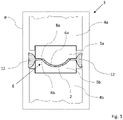
- the non-linear shape 6a of the pressure-forming zone is shown in figures 1b and 3 .
- the plane P is thus extending through the first rotational axis A R1 and the second rotational axis A R2 .
- the mould parts are thus moving through the plane P, and the non-linear configuration with the non-linear shape 6a of the pressure-forming zone 6 in the plane P may vary during the rotational movements of the mould parts.
- the non-linear configuration may have any varying shapes, such as for example varying between convex and concave shapes.
- the non-linear shape 6a of the pressure-forming zone 6 is used for producing three-dimensionally shaped cellulose products 1.
- the pressure-forming zone 6, may have a three-dimensional shape along at least one or more parts or sections of the respective peripheries of the mould parts, where the non-linear configuration of the pressure-forming zone 6 in the plane P is used for producing three-dimensional cellulose products 1 having non-planar shapes.
- the extension and the shape of the pressure-forming zone 6 in the plane P during movements of the mould parts may thus vary along the peripheral lengths of the mould parts depending on the shape of the cellulose products 1. It should be understood that the tangential direction D T referred to above is perpendicular to or essentially perpendicular to the plane P.
- the cellulose blank structure 2 air-formed from cellulose fibres is provided.
- the forming of the cellulose blank structure 2 may take place in an air-forming unit or similar arrangement, and if desired the cellulose blank structure 2 may be arranged in rolls or sheets before being transported to the rotary forming mould system 3.
- the air-forming may take place in direct connection to the rotary forming mould system 3 and thus the air-forming unit may be arranged in line with the rotary forming mould system 3.
- the cellulose blank structure 2 is then being transported to the rotary forming mould system 3, and the cellulose blank structure 2 is fed to a position between a first mould part 5a and a second mould part 5b.
- the transportation of the cellulose blank structure 2 in the rotary forming mould system 3 may be accomplished through the interaction between the cellulose blank structure 2 and the mould parts.
- the cellulose blank structure 2 is heated to a forming temperature in the range of 100°C to 300°C, and the heating may be arranged in connection to the mould parts, for example in a heating unit or through a stream of hot air or steam.
- Another alternative is to use heated mould parts for heating the cellulose blank structure 2.
- the cellulose products 1 are formed from the cellulose blank structure 2 in the rotary forming mould system 3, by pressing the heated cellulose blank structure 2 with a forming pressure P F of at least 1 MPa, preferably 4-20 MPa, in the pressure-forming zone 6 established between the first mould part 5a and the second mould part 5b.
- the first mould part 5a is rotating around the first rotational axis A R1 and the second mould part 5b is rotating around the second rotational axis A R2 .
- the pressure-forming zone 6 is formed as a gap and/or force section between the first mould part 5a and the second mould part 5b established during rotational movements of the first mould part 5a and the second mould part 5b in relation to each other.
- a highest instantaneous forming pressure may be exerted, depending on the design of the mould parts, on the cellulose blank structure 2 in the pressure-forming zone 6 in the plane P parallel to and extending through the first rotational axis A R1 and the second rotational axis A R2 during rotational movements of the first mould part 5a and the second mould part 5b, depending on the configuration of the mould parts.
- the highest instantaneous forming pressure is normally exerted in the plane P.
- the first mould part 5a and/or the second mould part 5b comprises a deformation element 7 arranged to exert the forming pressure P F on the cellulose blank structure 2 in the pressure-forming zone 6 during forming of the cellulose products 1.
- the pressure-forming zone 6 may have, depending on the construction of the mould parts, a different extension than the ones described above.
- the pressure-forming zone 6 may be arranged as a closed volume between the first mould part 5a and the second mould part 5b during forming of the cellulose products 1.
- the respective mould parts may be configured with walls or similar structural elements that are closing a forming volume between the mould parts during the forming process.
- the deformation element 7 is exerting an isostatic forming pressure on the cellulose blank structure in the closed volume between the mould parts.
- the forming pressure P F is thus in this embodiment an isostatic forming pressure of at least 1 MPa, preferably 4-20 MPa.
- the deformation element 7 may be attached to the first mould part 5a and/or the second mould part 5b with suitable attachment means, such as for example glue or mechanical fastening members. During the forming, the deformation element 7 is deformed to exert a pressure on the cellulose blank structure 2 and through the deformation an even pressure distribution is achieved, even if the cellulose products 1 are having complex three-dimensional shapes or if the cellulose blank structure 2 is having a varied thickness.
- the first mould part 5a is arranged as a female mould part
- the second mould part 5b is arranged as a male mould part with a deformation element 7, where the deformation element 7 is arranged to exert the forming pressure P F on the cellulose blank structure 2.
- the cellulose blank structure 2 is arranged between the first mould part 5a and the second mould part 5b.
- the cellulose product 1 is formed between the first mould part 5a and the second mould part 5b.
- the formed cellulose product 1 is ejected from the mould parts.
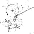
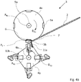
- the second mould part 5b is movably arranged in relation to the second base structure 4b, and a first actuator 11a and a second actuator 11b, or similar arrangements, are used for moving the second mould part 5b.
- the first actuator 11a is used for a tilting movement of the second mould part 5b in relation to the base structure 4b
- the second actuator 11b is used for an inwards-outwards movement of the second mould part 5b in relation to the base structure 4b.
- the first mould part 5a and the second mould part 5b may be arranged to close a volume between the mould parts during forming of the cellulose products 1, for example in the position illustrated in figure 4b .
- the pressure-forming zone 6 is established between the first mould part 5a and the second mould part 5b during forming of the cellulose products 1.
- the first mould part and/or the second mould part may if suitable be provided with cutting edges.
- the deformation element 7 is being deformed during the forming process, and the deformation element 7 is during forming of the cellulose products 1 arranged to exert a forming pressure P F on the cellulose blank structure 2.
- the deformation element 7 is made of a material that can be deformed when a force or pressure is applied.
- the deformation element 7 can be made of an elastic material capable of recovering size and shape after deformation.
- the deformation element 7 may further be made of a material with suitable properties that is withstanding the high forming pressure and temperature levels used when forming the cellulose products 1.
- the deformation element 7 is deformed to exert the forming pressure P F on the cellulose blank structure 2.
- P F forming pressure
- Certain elastic or deformable materials have fluid-like properties when being exposed to high pressure levels. If the deformation element 7 is made of such a material, an even pressure distribution can be achieved in the forming process, where the pressure exerted on the cellulose blank structure 2 from the deformation element 7 is equal or essentially equal in all directions between the mould parts. When the deformation element 7 during pressure is in its fluid-like state, a uniform fluid-like pressure distribution is achieved. The forming pressure is with such a material thus applied to the cellulose blank structure 2 from all directions, and the deformation element 7 is in this way during the forming of the cellulose products 1 exerting the isostatic forming pressure on the cellulose blank structure 2.
- the isostatic forming pressure from the deformation element 7 is establishing a uniform pressure in all directions on the cellulose blank structure 2.
- the isostatic forming pressure is providing an efficient forming process of the cellulose products 1, and the cellulose products 1 can be produced with high quality even if having complex shapes.
- the deformation element 7 may be made of a suitable structure of elastomeric material, where the material has the ability to establish a uniform pressure on the cellulose blank structure 2 during the forming process.
- the deformation element 7 is made of a massive structure or an essentially massive structure of silicone rubber, polyurethane, polychloroprene, or rubber with a hardness in the range 20-90 Shore A.
- Other materials for the deformation element 7 may for example be suitable gel materials, liquid crystal elastomers, and MR fluids.
- the deformation element 7 may also be configured as a thin membrane with a fluid that is exerting the forming pressure on the cellulose blank structure 2.
- the cellulose blank structure 2 is fed during forming of the cellulose products 1 between the first mould part 5a and the second mould part 5b with a transportation speed S T corresponding to the peripheral rotational speed S R1 of the first mould part 5a and the peripheral rotational speed S R2 of the second mould part 5b in the pressure-forming zone 6.
- the first rotational axis A R1 and the second rotational axis A R2 may be arranged in a parallel relationship to each other, as schematically illustrated in figure 1a .
- the first mould part 5a is rotating around the first rotational axis A R1 in a first rotational direction D R1 ; and the second mould part 5b is rotating around the second rotational axis A R2 in a second rotational direction D R2 .
- the first rotational direction D R1 is opposite the second rotational direction D R2 .
- the first mould part 5a may comprise a first cutting edge 8a, and/or the second mould part 5b a second cutting edge 8b, as schematically illustrated in figure 1a .
- the first cutting edge 8a and the second cutting edge 8b may have a shape or contour corresponding to the shape or contour of the cellulose products 1 to be produced.
- the first cutting edge 8a may be configured to interact with the second cutting edge 8b for removing parts of the cellulose blank structure 2 that are not art of the formed cellulose products 1.
- the first cutting edge 8a is arranged in an interacting relationship to the second cutting edge 8b during rotational movements of the first mould part 5a and the second mould part 5b.
- the cutting edges are arranged for removing unwanted residual cellulose fibres 12 from the cellulose blank structure, as schematically illustrated in figure 3 , and the cut residual cellulose fibres 12 may be reused for forming new cellulose blank structures if desired.
- only one of the mould parts may be arranged with a cutting edge, where the cutting edge may be arranged to interact with a part of the other mould part for cutting residual cellulose fibres from the cellulose blank structure.
- the cutting edge may have a shape or contour corresponding to the shape or contour of the cellulose products 1 to be produced.
- the first cutting edge 8a is configured to interact with the second mould part 5b, or alternatively during rotational movements of the first mould part 5a and the second mould part 5b the second cutting edge 8b is configured to interact with the first mould part 5a.
- the rotary forming mould system 3 for producing cellulose products 1 from a cellulose blank structure 2 is constructed with a compact and efficient design.
- the first base structure 4a is arranged inside the second base structure 4b.
- the first mould part 5a is configured for rotating around a first rotational axis A R1 in a first rotational direction D R1
- the second mould part 5b is configured for rotating around the second rotational axis A R2 in a second rotational direction D R2 .
- the first rotational direction D R1 is the same as the second rotational direction D R2 .
- the first rotational axis A R1 and the second rotational axis A R2 are suitably arranged in a parallel relationship to each other. If desired, the first rotational axis A R1 and the second rotational axis A R2 may instead be arranged in a non-parallel relationship to each other.
- the forming process is similar to the ones described in the embodiments above but with different relative movements of the mould parts.
- the mould parts may have the same configurations and functions as described in the different embodiments above.
- a first axle structure 9a may be arranged for rotating the first base structure 4a and the first mould parts 5a around the first rotational axis A R1 in the first rotational direction D R1 .
- the first axle structure 9a may be attached to the first base structure 4a with suitable fastening means, and the first axle structure 9a may be journally attached to a frame structure or similar arrangement via suitable bearings.
- a second axle structure 9b may be arranged for rotating the second base structure 4b and the second mould parts 5b around the second rotational axis A R2 in the second rotational direction D R2 .
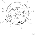
- the second axle structure 9b may be attached to the second base structure 4b with suitable fastening means, and the second axle structure 9a may be journally attached to the frame structure or similar arrangement via suitable bearings. As illustrated in figure 5 , the number of first mould parts 5a may differ from the number of second mould parts 5b.
- the rotary forming mould system 3 may comprise one or more further mould parts, where the one or more further mould parts each may be arranged to rotate around a rotational axis.
- the rotational axes of the one or more further mould parts may be arranged in a parallel or non-parallel relationship in relation to the first rotational axis and/or the second rotational axis.
- the forming mould system may comprise at least one third mould part in addition to the at least one first mould part and the at least one second mould part.
- the at least one third mould part may be rotatably arranged in relation to the at least one first mould part and the at least one second mould part.
- the at least one first mould part, the at least one second mould part, and the at least one at least one third mould part are rotatably interacting with each other.
- the forming mould system may in a similar way comprise at least one fourth mould part in addition to the at least one first mould part, the at least one second mould part, and the at least one third mould part.
- the cellulose blank structure 2 may comprise one or more additives that are altering the mechanical, hydrophobic, and/or oleophobic properties of the cellulose products 1. Tests have shown that if the cellulose blank structure 2 contains at least 70% of cellulose fibres, desired mechanical properties of the cellulose products 1 can be achieved. In order to achieve the desired properties of the formed cellulose products 1, the cellulose fibres should be strongly bonded to each other through fibril aggregation in a way so that the resulting cellulose products 1 will have good mechanical properties. The additives used may therefore not impact the bonding of the cellulose fibres during the forming process to a high extent.
- the cellulose blank structure may 2 have a material composition of 70-99.9% dry wt cellulose fibres and 0.1-30% dry wt of the one or more additives.
- the cellulose blank structure 2 may have a material composition of 80-99.9% dry wt cellulose fibres and 0.1-20% dry wt of the one or more additives.
- the cellulose blank structure 2 may have a material composition of 90-99.9% dry wt cellulose fibres and 0.1-10% dry wt of the one or more additives.
- the cellulose products 1 can have different properties.
- the one or more additives of the cellulose blank structure 2 may be, as a non-limiting example, starch compounds, rosin compounds, butanetetracarboxylic acid, gelatin compounds, alkyl ketene dimer (AKD), Alkenyl Succinic Anhydride (ASA), and/or flourocarbons. These additives are commonly used in the forming of cellulose products and are therefore not described in detail. Starch compounds, gelatin compounds, butanetetracarboxylic acid, and fluorocarbons may for example be used for altering the mechanical properties, such as strength or stiffness, of the cellulose product.
- Rosin compounds, alkyl ketene dimer (AKD), Alkenyl Succinic Anhydride (ASA), and fluorocarbons may for example be used for altering the hydrophobic properties of the cellulose products. Fluorocarbons may for example be used also for altering the oleophobic properties of the cellulose products 1.
- the one or more additives of the cellulose blank structure 2 may be added to the cellulose blank structure 2 before forming the cellulose products 1, for example when dry-forming the cellulose blank structure 2.
Landscapes
- Engineering & Computer Science (AREA)
- Mechanical Engineering (AREA)
- Life Sciences & Earth Sciences (AREA)
- Forests & Forestry (AREA)
- Manufacturing & Machinery (AREA)
- Nonwoven Fabrics (AREA)
- Paper (AREA)
- Polysaccharides And Polysaccharide Derivatives (AREA)
- Blow-Moulding Or Thermoforming Of Plastics Or The Like (AREA)
Description
- The present disclosure relates to a method for producing cellulose products from an air-formed cellulose blank structure in a rotary forming mould system. The disclosure further relates to a rotary forming mould system.
WO 2017/160218 A1 discloses a prior art method and system for producing discrete three-dimensional cellulose products from an air-formed cellulose blank structure in a forming mould. - Cellulose fibres are often used as raw material for producing or manufacturing products. Products formed of cellulose fibres can be used in many different situations where there is a need for having sustainable products. A wide range of products can be produced from cellulose fibres and a few examples are disposable plates and cups, blank structures and packaging materials.
- Forming moulds are commonly used when manufacturing cellulose products from raw materials including cellulose fibres, and traditionally the cellulose products have been produced with wet-forming techniques. A material commonly used for cellulose fibre products is wet moulded pulp. Wet moulded pulp has the advantage of being considered as a sustainable packaging material, since it is produced from biomaterials and can be recycled after use. Consequently, wet moulded pulp has been quickly increasing in popularity for different applications. Wet moulded pulp articles are generally formed by immersing a suction forming mould into a liquid or semi liquid pulp suspension or slurry comprising cellulose fibres, and when suction is applied, a body of pulp is formed with the shape of the desired product by fibre deposition onto the forming mould. With all wet-forming techniques there is a need for drying of the wet moulded product, where the drying is a very time and energy consuming part of the production. The demands on aesthetical, chemical and mechanical properties of cellulose products are increasing, and due to the properties of wet-formed cellulose products, the mechanical strength, flexibility, freedom in material thickness, and chemical properties are limited. It is also difficult in wet-forming processes to control the mechanical properties of the products with high precision.
- One development in the field of producing cellulose products is the forming of cellulose fibres without using wet-forming techniques. Instead of forming the cellulose products from a liquid or semi liquid pulp suspension or slurry, an air-formed cellulose blank is used. The air-formed cellulose blank is inserted into a forming mould and during the forming of the cellulose products the cellulose blank is subjected to a high forming pressure and a high forming temperature. The forming systems used for forming cellulose products from air-formed cellulose blank structures are limited in production capacity, since the forming of the cellulose products take place in forming systems with relatively long cycle times. The high pressure needed when forming the cellulose products is limiting the number of products that can be formed in a single pressure forming step.
- There is thus a need for an improved method and system for forming cellulose products from an air-formed cellulose blank structure.
- The invention is defined by the features of
independent claims - An object of the present disclosure is to provide a method for producing cellulose products from an air-formed cellulose blank structure and a rotary forming mould system where the previously mentioned problems are avoided. This object is at least partly achieved by the features of the independent claims. The dependent claims contain further developments of the method for producing cellulose products and the rotary forming mould system.
- The disclosure concerns a method for producing discrete three-dimensional cellulose products from an air-formed cellulose blank structure in a rotary forming mould system. The rotary forming mould system comprises at least one first mould part and at least one second mould part, where the at least one first mould part and the at least one second mould part are rotatably arranged in relation to each other. During rotational movements the at least one first mould part is rotatably interacting with the at least one second mould part. The method comprises the steps; providing the air-formed cellulose blank structure, wherein the cellulose blank structure is air-formed from cellulose fibres; transporting the air-formed cellulose blank structure to the rotary forming mould system; feeding the air-formed cellulose blank structure to a position between a first mould part and a second mould part, and heating the air-formed cellulose blank structure to a forming temperature in the range of 100°C to 300°C; forming the three-dimensional cellulose products from the air-formed cellulose blank structure in the rotary forming mould system, by pressing the heated air-formed cellulose blank structure with a forming pressure of at least 1 MPa, preferably 4-20 MPa, between the first mould part and the second mould part, where during forming the first mould part is rotating around a first rotational axis and the second mould part is rotating around a second rotational axis.
- Advantages with these features are that the forming of the discrete three-dimensional cellulose products from the air-formed cellulose blank structure can be made with an increased production speed, since the rotational movements of the mould parts are reducing the cycle times compared to traditional forming methods. In the traditional forming methods used, the reciprocating movement establishing the high pressure needed when forming the cellulose products is limiting the number of products that can be formed in a single pressure forming step, and the rotary forming of cellulose products is providing a way to overcome this problem since no mass has to be accelerated and single products can be produced with high speed in continuous rotating movements. With discrete cellulose products is meant that individual or separated products are formed in the process, which is different from the forming of continuous structures, such as webs or sheets of cellulose material. The formed discrete cellulose products are having a three-dimensional shape, which is different from flat or two-dimensional shapes. Examples of three-dimensional products according to the disclosure are disposable cutlery, plates, cups and bowls; three-dimensional packaging structures or packaging inserts; coffee pods; coat-hangers; and meat trays.
- According to an aspect of the disclosure, the air-formed cellulose blank structure has a dry basis weight in the range of 200-3000 g/m2, preferably 300-3000 g/m2, and more preferably 400-3000 g/m2. The air-formed cellulose blank structure with these properties are suitable for the forming of the three-dimensional cellulose products. The cellulose blank structure is a relatively thick and fluffy structure compared to traditional wet-laid paper or tissue structures. The bulky cellulose blank structure is compacted during the forming process, and the cellulose fibres in the three-dimensional cellulose products are strongly bonded to each other with hydrogen bonds, providing a stiff compacted three-dimensional product structure.
- According to an aspect of the disclosure, the forming pressure is applied to the air-formed cellulose blank structure in a pressure-forming zone established between the first mould part and the second mould part. The pressure-forming zone is formed as a gap and/or force section between the first mould part and the second mould part established during rotational movements of the first mould part and the second mould part in relation to each other. The pressure-forming zone has an extension between the first mould part and the second mould part where the first mould part and/or the second mould part are exerting pressure on the air-formed cellulose blank structure during forming of the three-dimensional cellulose products. The pressure-forming zone is thus a zone formed between the first mould part and the second mould part during the rotational movements of the interacting mould parts.
- According to another aspect of the disclosure, the pressure-forming zone has a non-linear configuration in a plane parallel to and extending through the first rotational axis and the second rotational axis at least partly along a first peripheral length of the first mould part and a second peripheral length of the second mould part during rotational movements of the first mould part and the second mould part. The non-linear configuration in the plane is providing three-dimensionally shaped products.
- According to an aspect of the disclosure, the method further comprises the step; exerting a highest instantaneous forming pressure on the air-formed cellulose blank structure in a plane parallel to and extending through the first rotational axis and the second rotational axis during rotational movements of the first mould part and the second mould part. The highest instantaneous forming pressure is the highest pressure level exerted on the air-formed cellulose blank structure during the rotary forming of the three-dimensional cellulose products when using for example mould parts with high stiffness.
- According to another aspect of the disclosure, the first mould part and/or the second mould part comprises a deformation element arranged to exert the forming pressure on the air-formed cellulose blank structure during forming of the three-dimensional cellulose products. The deformation element is used for evening out the pressure distribution in the forming mould for an efficient forming of the three-dimensional cellulose products.
- According to an aspect of the disclosure, the pressure-forming zone is arranged as a closed volume between the first mould part and the second mould part during forming of the three-dimensional cellulose products. The closed volume is securing an efficient forming when using the deformation element and enables more steep deep drawing angles in different directions of the three-dimensional cellulose products.
- According to another aspect of the disclosure, the forming pressure is an isostatic forming pressure of at least 1 MPa, preferably 4-20 MPa. The isostatic forming pressure is providing an efficient forming of the three-dimensional cellulose products, for example, when the products have complex three-dimensional shapes.
- According to a further aspect of the disclosure, the method further comprises the step; feeding the air-formed cellulose blank structure during forming of the three-dimensional cellulose products between the first mould part and the second mould part with a transportation speed corresponding to the rotational speed of the first mould part and the rotational speed of the second mould part in the pressure-forming zone. The transportation speed corresponding to the rotational speeds of the mould parts is securing an efficient feeding of the air-formed cellulose blank structure with minimized risks for rupturing the air-formed cellulose blank structure.
- According to an aspect of the disclosure, the first rotational axis and the second rotational axis are arranged in a parallel relationship to each other. With this relationship between the rotational axes, a compact design of the rotary forming mould system can be achieved.
- According to another aspect of the disclosure, the method further comprises the steps; rotating the first mould part around the first rotational axis in a first rotational direction; and rotating the second mould part around the second rotational axis in a second rotational direction, where the first rotational direction is opposite the second rotational direction, or where the first rotational direction is the same as the second rotational direction. With the opposite rotational directions, the mould parts can interact in an efficient way when forming the three-dimensional cellulose products. With the same rotational directions, the rotary forming mould system can be constructed with a compact design.
- According to a further aspect of the disclosure, the first mould part comprises a first cutting edge, and/or the second mould part comprises a second cutting edge. During rotational movements of the first mould part and the second mould part the first cutting edge is configured to interact with the second cutting edge, or during rotational movements of the first mould part and the second mould part the first cutting edge is configured to interact with the second mould part, or during rotational movements of the first mould part and the second mould part the second cutting edge is configured to interact with the first mould part. The cutting edges are arranged for removing unwanted residual cellulose fibres from the air-formed cellulose blank structure. The cut residual cellulose fibres may be reused for air-forming cellulose blank structures if desired.
- The disclosure further concerns a rotary forming mould system arranged for forming discrete three-dimensional cellulose products from an air-formed cellulose blank structure. The rotary forming mould system comprises at least one first mould part and at least one second mould part, where the at least one first mould part and the at least one second mould part are rotatably arranged in relation to each other. During rotational movements, the at least one first mould part is rotatably interacting with the at least one second mould part. During forming of the three-dimensional cellulose products, the rotary forming mould system is configured to heating the air-formed cellulose blank structure to a forming temperature in the range of 100°C to 300°C, and configured to forming the three-dimensional cellulose products from the air-formed cellulose blank structure in the rotary forming mould system, by pressing the heated air-formed cellulose blank structure with a forming pressure PF of at least 1 MPa, preferably 4-20 MPa, between the first mould part and the second mould part, where during forming the first mould part is arranged to rotate around a first rotational axis and the second mould part is arranged to rotate around a second rotational axis. The forming of the three-dimensional cellulose products from the air-formed cellulose blank structure can be made with an increased production speed in the rotary forming mould system, since the rotational movements of the mould parts are reducing the cycle times compared to traditional forming methods.
- According to an aspect of the disclosure, the air-formed cellulose blank structure has a dry basis weight in the range of 200-3000 g/m2, preferably 300-3000 g/m2, and more preferably 400-3000 g/m2, providing suitable properties of the air-formed cellulose blank structure for forming in the forming mould system.
- According to an aspect of the disclosure, the rotary forming mould system further comprises a first base structure and a second base structure. The at least one first mould part is arranged on the first base structure, and the at least one second mould part is arranged on the second base structure. The first base structure and the second base structure are rotatably arranged in relation to each other. The base structures are arranged for holding the mould parts during the rotary forming process.
- According to another aspect of the disclosure, the forming pressure is applied in a pressure-forming zone established between the first mould part and the second mould part. The pressure-forming zone is configured as a gap and/or force section between the first mould part and the second mould part established during rotational movements of the first mould part and the second mould part in relation to each other. The pressure-forming zone has an extension between the first mould part and the second mould part where the first mould part and/or the second mould part are exerting pressure on the air-formed cellulose blank structure during forming of the three-dimensional cellulose products.
- According to another aspect of the disclosure, the pressure-forming zone is configured with a non-linear shape in a plane parallel to and extending through the first rotational axis and the second rotational axis at least partly along a first peripheral length of the first mould part and a second peripheral length of the second mould part during rotational movements of the first mould part and the second mould part.
- According to an aspect of the disclosure, the first rotational axis and the second rotational axis are arranged in a parallel relationship to each other.
- According to another aspect of the disclosure, the first mould part and the second mould part during are rotational movements configured to exerting a highest instantaneous forming pressure on the air-formed cellulose blank structure in a plane parallel to and extending through the first rotational axis and the second rotational axis. The highest instantaneous forming pressure is the highest pressure level exerted on the air-formed cellulose blank structure during the rotary forming of the three-dimensional cellulose products when using for example mould parts with high stiffness.
- According to a further aspect of the disclosure, the first mould part and/or the second mould part comprises a deformation element configured to exerting the forming pressure on the air-formed cellulose blank structure during forming of the three-dimensional cellulose products. The deformation element is used for evening out the pressure distribution in the forming mould for an efficient forming of the three-dimensional cellulose products.
- According to an aspect of the disclosure, the pressure-forming zone is arranged as a closed volume between the first mould part and the second mould part during forming of the three-dimensional cellulose products. The closed volume is securing an efficient forming when using the deformation element.
- According to another aspect of the disclosure, the forming pressure is an isostatic forming pressure of at least 1 MPa, preferably 4-20 MPa.
- According to a further aspect of the disclosure, the first mould part is configured for rotating around the first rotational axis in a first rotational direction, and the second mould part is configured for rotating around the second rotational axis in a second rotational direction. The first rotational direction is opposite the second rotational direction, or the first rotational direction is the same as the second rotational direction.
- According to an aspect of the disclosure, the first mould part is configured to be removably attached to the first base structure and/or the second mould part is configured to be removably attached to the second base structure. The base structures can thus be used for different types of mould parts.
- According to another aspect of the disclosure, the first mould part comprises a first cutting edge, and/or the second mould part comprises a second cutting edge. During rotational movements of the first mould part and the second mould part the first cutting edge is configured to interact with the second cutting edge, or during rotational movements of the first mould part and the second mould part the first cutting edge is configured to interact with the second mould part, or during rotational movements of the first mould part and the second mould part the second cutting edge is configured to interact with the first mould part. The cutting edges are arranged for removing unwanted residual cellulose fibres from the air-formed cellulose blank structure, and the cut residual cellulose fibres may be reused for air-forming cellulose blank structures if desired.
- The disclosure will be described in greater detail in the following, with reference to the attached drawings, in which
- Fig. 1a-b
- show schematically, in perspective views a rotary forming mould system and a section of the rotary forming mould system according to the disclosure,
- Fig. 2a-b
- show schematically, in side views the rotary forming mould system and a section of the rotary forming mould system according to the disclosure,
- Fig. 3
- shows schematically, in a front view a section of the rotary forming mould system according to the disclosure,
- Fig. 4a-c
- show schematically, in side views an alternative embodiment of the rotary forming mould system according to the disclosure, and
- Fig. 5
- shows schematically, in a side view an alternative embodiment of the forming mould system according to the disclosure.
- Various aspects of the disclosure will hereinafter be described in conjunction with the appended drawings to illustrate and not to limit the disclosure, wherein like designations denote like elements, and variations of the described aspects are not restricted to the specifically shown embodiments, but are applicable on other variations of the disclosure.
- In
figures 1a-b and2a-b , a rotary formingmould system 3 for producing discrete three-dimensional cellulose products 1 from an air-formed celluloseblank structure 2 is schematically shown. The celluloseblank structure 2 may be a pre-formed structure comprising cellulose fibres, where the cellulose fibres are carried and formed to the fibreblank structure 2 by air as carrying medium in an air-forming process. - With discrete cellulose products is meant that individual or separated products are formed in the process, which is different from the forming of continuous structures, such as webs or sheets of cellulose material. The formed discrete cellulose products are having a three-dimensional shape, which is different from flat or two-dimensional shapes. Cellulose structures, such as airlaid webs, tissue webs, boards and other flat cellulose fibre webs are defined as two-dimensional structures, which are different from the discrete three-dimensional cellulose products according to the disclosure. The flat structures are defined as two-dimensional even if they are provided with embossed surfaces or other surface structures. Examples of three-dimensional products according to the disclosure are disposable cutlery, plates, cups and bowls; three-dimensional packaging structures or packaging inserts; coffee pods; coat-hangers; and meat trays. Any type of cellulose product having a well-defined extension in three dimensions may be produced with the method and system according to the disclosure.
- With a cellulose
blank structure 2 is meant a fibre web structure produced from cellulose fibres. With air-forming of the celluloseblank structure 2 is meant the formation of a cellulose blank structure in a dry-forming process in which cellulose fibres are air-formed to produce the celluloseblank structure 2. When forming the celluloseblank structure 2 in the air-forming process, the cellulose fibres are carried and formed to the fibreblank structure 2 by air as carrying medium. This is different from a normal papermaking process or a traditional wet-forming process, where water is used as carrying medium for the cellulose fibres when forming the paper or fibre structure. In the air-forming process, small amounts of water or other substances may if desired be added to the cellulose fibres in order to change the properties of thecellulose products 1, but air is still used as carrying medium in the forming process. The celluloseblank structure 2 may have a dryness that is mainly corresponding to the ambient humidity in the atmosphere surrounding the dry-formed celluloseblank structure 2. As an alternative, the dryness of the celluloseblank structure 2 may be controlled in order to have a suitable dryness level when forming thecellulose products 1. - The cellulose
blank structure 2 may be formed of cellulose fibres in a conventional dry-forming process and be configured in different ways. For example, the celluloseblank structure 2 may have a composition where the fibres are of the same origin or alternatively contain a mix of two or more types of cellulose fibres, depending on the desired properties of thecellulose products 1. The cellulose fibres used in the celluloseblank structure 2 are during the forming of thecellulose products 1 strongly bonded to each other with hydrogen bonds. The cellulose fibres may be mixed with other substances or compounds to a certain amount as will be further described below. With cellulose fibres is meant any type of cellulose fibres, such as natural cellulose fibres or manufactured cellulose fibres. - The cellulose
blank structure 2 may have a single-layer or a multi-layer configuration. A celluloseblank structure 2 having a single-layer configuration is referring to a cellulose blank structure that is formed of one layer containing cellulose fibres. A celluloseblank structure 2 having a multi-layer configuration is referring to a cellulose blank structure that is formed of two or more layers containing cellulose fibres, where the layers may have the same or different compositions or configurations. An additional layer comprising cellulose fibres may be arranged as a carrying layer for the celluloseblank structure 2, and the additional layer may have a higher tensile strength than the celluloseblank structure 2. This may be useful when the celluloseblank structure 2 has a composition with a low tensile strength in order to avoid that the celluloseblank structure 2 will break during the forming of thecellulose products 1. The additional layer with a higher tensile strength acts in this way as a supporting structure for the celluloseblank structure 2. The additional layer may for example be a tissue layer containing cellulose fibres, an airlaid structure comprising cellulose fibres, or other suitable layer structures. - The air-formed cellulose
blank structure 2 according to the disclosure has suitably a dry basis weight in the range of 200-3000 g/m2, preferably 300-3000 g/m2, and more preferably 400-3000 g/m2. The dry basis weight values described are web-average values, and test have shown that these web-average values are suitable when forming thecellulose products 1. It should be understood that the celluloseblank structure 2 is a relatively thick and fluffy structure compared to traditional wet-laid paper or tissue structures. As an example, tests have shown that the density of the celluloseblank structure 2 when arranged in the formingmould system 3 may be lower than 100 kg/m3, which is providing a bulky structure suitable for forming in the formingmould system 3. It should be understood that the density is depending on the dry-forming process and grade of pre-compression of the celluloseblank structure 2 before the forming of thecellulose products 1 in the formingmould system 3. When determining the density, a pressure of 0.5 kPa is applied to a sample piece of the celluloseblank structure 2. The measured thickness of the celluloseblank structure 2 under load together with the basis weight is used for determining the density. The celluloseblank structure 2 is compacted during the forming process, and the cellulose fibres in the three-dimensional cellulose products 1 are strongly bonded to each other with hydrogen bonds, providing a stiff compacted three-dimensional product structure. - As for example illustrated in
figures 1a-b ,2a-b and3 , the rotary formingmould system 3 according to the different embodiments of the disclosure comprises at least onefirst mould part 5a and at least onesecond mould part 5b. The at least onefirst mould part 5a and the at least onesecond mould part 5b are rotatably arranged in relation to each other, and arranged as discrete mould parts that are interacting with each other during the forming of the three-dimensional cellulose products 1. During rotational movements the at least onefirst mould part 5a is rotatably interacting with at least one correspondingsecond mould part 5b for forming the three-dimensional cellulose products 1, and the mould parts are adapted to move in relation to each other for establishing a desired shape of thecellulose products 2 produced in the rotary formingmould system 3. Eachfirst mould part 5a is interacting with a correspondingsecond mould part 5b. The rotary formingmould system 3 further comprises a rotatably arrangedfirst base structure 4a, and a rotatably arrangedsecond base structure 4b. The least onefirst mould part 5a is arranged on thefirst base structure 4a, and the at least onesecond mould part 5b is arranged on thesecond base structure 4b. In the embodiment shown infigures 1a-b and2a-b , thefirst base structure 4a and thesecond base structure 4b each comprises a plurality of discretefirst mould parts 5a and discretesecond mould parts 5b respectively. Thefirst base structure 4a and thesecond base structure 4b are rotatably arranged in relation to each other, and during rotational movements of thefirst base structure 4a and thesecond base structure 4b thefirst mould parts 5a are rotatably interacting with correspondingsecond mould parts 5b, as will be further described below. - The
first base structure 4a and thesecond base structure 4b may have any suitable structural configurations for holding the first and second mould parts respectively. The base structures may be formed as rotating constructions of steel or other suitable metals, composite materials, plastic materials or combinations of different materials. Thefirst base structure 4a and thesecond base structure 4b are each driven by a suitable power source, such as electric motors. Alternatively, thefirst base structure 4a and thesecond base structure 4b are driven by the same electric motor through for example a belt drive, chain drive, or gear drive arrangement. - The
first mould parts 5a and thesecond mould parts 5b are attached to the respective base structures with suitable fastening means, such as for example bolts, screws, rivets, or other fastening elements, and the mould parts may be releasably attached for a simple removal of the mould parts when needed. Thus, the at least onefirst mould part 5a may be configured to be removably attached to thefirst base structure 4a, and/or the at least onesecond mould part 5b may be configured to be removably attached to thesecond base structure 4b. In alternative embodiments, the at least onefirst mould part 5a and/or the at least onesecond mould part 5b may suitably be movably arranged in relation to the respective base structures during forming of thecellulose products 1. Movably arranged mould parts may be used when the cellulose products are having complex three-dimensional shapes. - The
first mould parts 5a and thesecond mould parts 5b are arranged to interact with each other during the forming of thecellulose products 1, and are shaped to form the discrete three-dimensional cellulose products during the rotational movements of the first and second mould parts in relation to each other. Thefirst mould parts 5a and thesecond mould parts 5b thus have mould shapes corresponding to the three-dimensional shape of the cellulose products to be produced. As an example, thefirst mould parts 5a may be shaped as male moulds and thesecond mould parts 5b may be shaped as corresponding female moulds, or alternatively thefirst mould parts 5a may be shaped as female moulds and thesecond mould parts 5b may be shaped as corresponding male moulds. Thefirst mould parts 5a and thesecond mould parts 5b may each have both male and female mould sections, depending on the shape of the three-dimensional cellulose products 1 to be produced, as schematically illustrated infigure 2b , where a three-dimensional disposable cellulosic spoon is exemplified. Corresponding male and female mould sections of the respective mould parts are interacting with each other during the rotational movements of the mould parts. In this way, a three-dimensional shape of thecellulose products 1 is established between the mould parts. - The
first base structure 4a and thesecond base structure 4b may be formed as forming wheels having essentially circular peripheral shapes, and thefirst mould parts 5a and thesecond mould parts 5b are arranged on the outer peripheries of the respective base structures, as illustrated infigures 1a-b and2a-b . The respective mould parts may have curved shapes to match the base structures, and the curved shapes are enabling the rotating interaction between thefirst mould parts 5a and thesecond mould parts 5b. The base structures may have other designs and configurations if desired. - The
first mould part 5a is configured for rotating around a first rotational axis AR1 in a first rotational direction DR1, and thesecond mould part 5b is configured for rotating around the second rotational axis AR2 in a second rotational direction DR2. As illustrated infigures 1a-b and2b , the first rotational direction DR1 is opposite the second rotational direction DR2. The first rotational axis AR1 and the second rotational axis AR2 are suitably arranged in a parallel relationship to each other. If desired, the first rotational axis AR1 and the second rotational axis AR2 may instead be arranged in a non-parallel relationship to each other. - A
first axle structure 9a may be arranged for rotating thefirst base structure 4a and thefirst mould parts 5a around the first rotational axis AR1 in the first rotational direction DR1. Thefirst axle structure 9a may be attached to thefirst base structure 4a with suitable fastening means, and thefirst axle structure 9a may be journally attached to a frame structure or similar arrangement via suitable bearings. Asecond axle structure 9b may be arranged for rotating thesecond base structure 4b and thesecond mould parts 5b around the second rotational axis AR2 in the second rotational direction DR2. Thesecond axle structure 9b may be attached to thesecond base structure 4b with suitable fastening means, and thesecond axle structure 9a may be journally attached to the frame structure or similar arrangement via suitable bearings. - As described above, during rotational movements of the
first mould parts 5a andsecond mould parts 5b, thefirst mould parts 5a are rotatably interacting with correspondingsecond mould parts 5b. Eachfirst mould part 5a on thefirst base structure 4a has a correspondingsecond mould part 5b on thesecond base structure 4b, where the corresponding mould parts are cooperating when forming thecellulose products 1. When rotating around the respective rotational axes, thefirst mould parts 5a meet and interact with the correspondingsecond mould parts 5b, and thecellulose products 1 are formed in a space formed between thefirst mould parts 5a and thesecond mould parts 5b. - During forming of the three-
dimensional cellulose products 1, the rotary formingmould system 3 is configured to heating the celluloseblank structure 2 to a forming temperature in the range of 100°C to 300°C with suitable heating means. The celluloseblank structure 2 may for example be pre-heated in a heating unit, exposed to hot air or steam, or alternatively the mould parts may be heated. The rotary formingmould system 3 is further configured to forming thecellulose products 1 from the celluloseblank structure 2 in the rotary formingmould system 3, by pressing the heated celluloseblank structure 2 with a forming pressure PF of at least 1 MPa, preferably 4-20 MPa, between thefirst mould part 5a and thesecond mould part 5b. During forming, thefirst mould part 5a is rotating around the first rotational axis AR1 and thesecond mould part 5b is rotating around the second rotational axis AR2. The forming temperature of the celluloseblank structure 2 may for example be measured with suitable temperature sensors when the celluloseblank structure 2 is formed between the mould parts, such as for example temperature sensors integrated in the mould parts, or thermochromic temperature sensors arranged in connection to or in the celluloseblank structure 2. Other suitable sensors may for example be IR sensors measuring the temperature of the celluloseblank structure 2 directly after forming between the mould parts. - The forming pressure PF is applied to the cellulose
blank structure 2 in the space formed between thefirst mould part 5a and thesecond mould part 5b. More specifically, the forming pressure PF is applied in a pressure-formingzone 6 established between thefirst mould part 5a and thesecond mould part 5b, where the pressure-formingzone 6 is configured as a gap and/or force section between thefirst mould part 5a and thesecond mould part 5b. The gap and/or force section is established during rotational movements of thefirst mould part 5a and thesecond mould part 5b in relation to each other. With a gap section is meant that a gap is established between the mould parts in the pressure-formingzone 6, where thecellulose products 1 are formed in the gap from the celluloseblank structure 2. The amount of supplied cellulose fibres into the gap determines the obtained forming pressure in the gap. The first rotational axis AR1 is with this configuration arranged at a fixed distance from the second rotational axis AR2. A force section between the mould parts is referring to situations where there is no initial gap between the mould parts, and where a force F is exerted between the mould parts is used for forming the cellulose products, as schematically illustrated infigures 1a ,2a-b . This may be the case if therespective base structures blank structure 2 is arranged between the mould parts, since the mould parts through the spring-loaded configuration are allowed to move in relation to each other. The pressure-formingzone 6 is defined to have an extension between thefirst mould part 5a and thesecond mould part 5b where thefirst mould part 5a and/or thesecond mould part 5b are exerting pressure on the celluloseblank structure 2 during forming of thecellulose products 1. The pressure-formingzone 6 may vary for example depending on the type and design of mould parts used, the thickness and configuration of the celluloseblank structure 2, and the properties of the cellulose fibres in the celluloseblank structure 2. The pressure-formingzone 6 is illustrated infigures 2b and3 , and as shown infigure 2a , the pressure-formingzone 6 starts in a tangential direction DT where the mould parts interact with each other at a first zone end E1 where the celluloseblank structure 2 enters the gap between thefirst mould part 5a and thesecond mould part 5b, and where thefirst mould part 5a and/or thesecond mould part 5b start exerting pressure on the celluloseblank structure 2. When the mould parts are exerting pressure on the celluloseblank structure 2, the celluloseblank structure 2 is being deformed and compacted between the mould parts. The pressure-formingzone 6 ends in the tangential direction DT at a second zone end E2 where the celluloseblank structure 2 exits the gap between thefirst mould part 5a and thesecond mould part 5b, and where thefirst mould part 5a and/or thesecond mould part 5b are no longer exerting pressure on the celluloseblank structure 2. When the mould parts are no longer exerting pressure on the celluloseblank structure 2, the celluloseblank structure 2 has been formed into thecellulose products 1. The extension of the pressure-formingzone 6 in the tangential direction DT, and the positions of the first zone end E1 and the second zone end E2 may vary during the rotational movements of the mould parts depending on the configuration of the mould parts. - The
first mould parts 5a have a first extension along a firstouter periphery 10a of thefirst mould parts 5a with a first peripheral length LP1. Thesecond mould parts 5b have a second extension along a secondouter periphery 10b of thesecond mould parts 5b with a second peripheral length LP2. - As illustrated in
figures 1a-b ,2a-b and3 , the pressure-formingzone 6 may be configured with anon-linear shape 6a in a plane P parallel to and including the first rotational axis AR1 and the second rotational axis AR2 at least partly along the first peripheral length LP1 of thefirst mould part 5a and the second peripheral length LP2 of thesecond mould part 5b during rotational movements of thefirst mould part 5a and thesecond mould part 5b. Thenon-linear shape 6a of the pressure-forming zone is shown infigures 1b and3 . The plane P is thus extending through the first rotational axis AR1 and the second rotational axis AR2. During rotational movements, the mould parts are thus moving through the plane P, and the non-linear configuration with thenon-linear shape 6a of the pressure-formingzone 6 in the plane P may vary during the rotational movements of the mould parts. The non-linear configuration may have any varying shapes, such as for example varying between convex and concave shapes. Thenon-linear shape 6a of the pressure-formingzone 6 is used for producing three-dimensionally shapedcellulose products 1. The pressure-formingzone 6, may have a three-dimensional shape along at least one or more parts or sections of the respective peripheries of the mould parts, where the non-linear configuration of the pressure-formingzone 6 in the plane P is used for producing three-dimensional cellulose products 1 having non-planar shapes. The extension and the shape of the pressure-formingzone 6 in the plane P during movements of the mould parts may thus vary along the peripheral lengths of the mould parts depending on the shape of thecellulose products 1. It should be understood that the tangential direction DT referred to above is perpendicular to or essentially perpendicular to the plane P. - When producing the three-
dimensional cellulose products 1 in the rotary formingmould system 3, the celluloseblank structure 2 air-formed from cellulose fibres is provided. The forming of the celluloseblank structure 2 may take place in an air-forming unit or similar arrangement, and if desired the celluloseblank structure 2 may be arranged in rolls or sheets before being transported to the rotary formingmould system 3. If desired, the air-forming may take place in direct connection to the rotary formingmould system 3 and thus the air-forming unit may be arranged in line with the rotary formingmould system 3. The celluloseblank structure 2 is then being transported to the rotary formingmould system 3, and the celluloseblank structure 2 is fed to a position between afirst mould part 5a and asecond mould part 5b. The transportation of the celluloseblank structure 2 in the rotary formingmould system 3 may be accomplished through the interaction between the celluloseblank structure 2 and the mould parts. The celluloseblank structure 2 is heated to a forming temperature in the range of 100°C to 300°C, and the heating may be arranged in connection to the mould parts, for example in a heating unit or through a stream of hot air or steam. Another alternative is to use heated mould parts for heating the celluloseblank structure 2. Thecellulose products 1 are formed from the celluloseblank structure 2 in the rotary formingmould system 3, by pressing the heated celluloseblank structure 2 with a forming pressure PF of at least 1 MPa, preferably 4-20 MPa, in the pressure-formingzone 6 established between thefirst mould part 5a and thesecond mould part 5b. During forming, thefirst mould part 5a is rotating around the first rotational axis AR1 and thesecond mould part 5b is rotating around the second rotational axis AR2. As described above, the pressure-formingzone 6 is formed as a gap and/or force section between thefirst mould part 5a and thesecond mould part 5b established during rotational movements of thefirst mould part 5a and thesecond mould part 5b in relation to each other. - A highest instantaneous forming pressure may be exerted, depending on the design of the mould parts, on the cellulose
blank structure 2 in the pressure-formingzone 6 in the plane P parallel to and extending through the first rotational axis AR1 and the second rotational axis AR2 during rotational movements of thefirst mould part 5a and thesecond mould part 5b, depending on the configuration of the mould parts. When using stiff mould parts, the highest instantaneous forming pressure is normally exerted in the plane P. - In alternative embodiments, the
first mould part 5a and/or thesecond mould part 5b comprises adeformation element 7 arranged to exert the forming pressure PF on the celluloseblank structure 2 in the pressure-formingzone 6 during forming of thecellulose products 1. When using adeformation element 7, the pressure-formingzone 6 may have, depending on the construction of the mould parts, a different extension than the ones described above. When using thedeformation element 7, the pressure-formingzone 6 may be arranged as a closed volume between thefirst mould part 5a and thesecond mould part 5b during forming of thecellulose products 1. The respective mould parts may be configured with walls or similar structural elements that are closing a forming volume between the mould parts during the forming process. In this way, thedeformation element 7 is exerting an isostatic forming pressure on the cellulose blank structure in the closed volume between the mould parts. The forming pressure PF is thus in this embodiment an isostatic forming pressure of at least 1 MPa, preferably 4-20 MPa. - The
deformation element 7 may be attached to thefirst mould part 5a and/or thesecond mould part 5b with suitable attachment means, such as for example glue or mechanical fastening members. During the forming, thedeformation element 7 is deformed to exert a pressure on the celluloseblank structure 2 and through the deformation an even pressure distribution is achieved, even if thecellulose products 1 are having complex three-dimensional shapes or if the celluloseblank structure 2 is having a varied thickness. - In the embodiments illustrated in
figure 4a-c , thefirst mould part 5a is arranged as a female mould part, and thesecond mould part 5b is arranged as a male mould part with adeformation element 7, where thedeformation element 7 is arranged to exert the forming pressure PF on the celluloseblank structure 2. Infigure 4a , the celluloseblank structure 2 is arranged between thefirst mould part 5a and thesecond mould part 5b. Infigure 4b , thecellulose product 1 is formed between thefirst mould part 5a and thesecond mould part 5b. Infigure 4c , the formedcellulose product 1 is ejected from the mould parts. As illustrated infigures 4a-c , thesecond mould part 5b is movably arranged in relation to thesecond base structure 4b, and afirst actuator 11a and asecond actuator 11b, or similar arrangements, are used for moving thesecond mould part 5b. Thefirst actuator 11a is used for a tilting movement of thesecond mould part 5b in relation to thebase structure 4b, and thesecond actuator 11b is used for an inwards-outwards movement of thesecond mould part 5b in relation to thebase structure 4b. If an isostatic forming pressure is used, thefirst mould part 5a and thesecond mould part 5b may be arranged to close a volume between the mould parts during forming of thecellulose products 1, for example in the position illustrated infigure 4b . With this configuration of the rotary forming mould system, the pressure-formingzone 6 is established between thefirst mould part 5a and thesecond mould part 5b during forming of thecellulose products 1. The first mould part and/or the second mould part may if suitable be provided with cutting edges. - In the different embodiments described above, the
deformation element 7 is being deformed during the forming process, and thedeformation element 7 is during forming of thecellulose products 1 arranged to exert a forming pressure PF on the celluloseblank structure 2. To exert a required forming pressure PF on the celluloseblank structure 2, thedeformation element 7 is made of a material that can be deformed when a force or pressure is applied. For example, thedeformation element 7 can be made of an elastic material capable of recovering size and shape after deformation. Thedeformation element 7 may further be made of a material with suitable properties that is withstanding the high forming pressure and temperature levels used when forming thecellulose products 1. - During the forming process, the
deformation element 7 is deformed to exert the forming pressure PF on the celluloseblank structure 2. Through the deformation an even pressure distribution can be achieved, even if thecellulose products 1 are having complex three-dimensional shapes with cutouts, apertures and holes, or if the celluloseblank structure 2 used is having varying density, thickness, or grammage levels. - Certain elastic or deformable materials have fluid-like properties when being exposed to high pressure levels. If the
deformation element 7 is made of such a material, an even pressure distribution can be achieved in the forming process, where the pressure exerted on the celluloseblank structure 2 from thedeformation element 7 is equal or essentially equal in all directions between the mould parts. When thedeformation element 7 during pressure is in its fluid-like state, a uniform fluid-like pressure distribution is achieved. The forming pressure is with such a material thus applied to the celluloseblank structure 2 from all directions, and thedeformation element 7 is in this way during the forming of thecellulose products 1 exerting the isostatic forming pressure on the celluloseblank structure 2. The isostatic forming pressure from thedeformation element 7 is establishing a uniform pressure in all directions on the celluloseblank structure 2. The isostatic forming pressure is providing an efficient forming process of thecellulose products 1, and thecellulose products 1 can be produced with high quality even if having complex shapes. - The
deformation element 7 may be made of a suitable structure of elastomeric material, where the material has the ability to establish a uniform pressure on the celluloseblank structure 2 during the forming process. As an example, thedeformation element 7 is made of a massive structure or an essentially massive structure of silicone rubber, polyurethane, polychloroprene, or rubber with a hardness in the range 20-90 Shore A. Other materials for thedeformation element 7 may for example be suitable gel materials, liquid crystal elastomers, and MR fluids. Thedeformation element 7 may also be configured as a thin membrane with a fluid that is exerting the forming pressure on the celluloseblank structure 2. - In the different embodiments described, as schematically illustrated in
figure 2b , the celluloseblank structure 2 is fed during forming of thecellulose products 1 between thefirst mould part 5a and thesecond mould part 5b with a transportation speed ST corresponding to the peripheral rotational speed SR1 of thefirst mould part 5a and the peripheral rotational speed SR2 of thesecond mould part 5b in the pressure-formingzone 6. - The first rotational axis AR1 and the second rotational axis AR2 may be arranged in a parallel relationship to each other, as schematically illustrated in
figure 1a . Thefirst mould part 5a is rotating around the first rotational axis AR1 in a first rotational direction DR1; and thesecond mould part 5b is rotating around the second rotational axis AR2 in a second rotational direction DR2. As illustrated with arrows infigure 1b , the first rotational direction DR1 is opposite the second rotational direction DR2. - The
first mould part 5a may comprise afirst cutting edge 8a, and/or thesecond mould part 5b asecond cutting edge 8b, as schematically illustrated infigure 1a . Thefirst cutting edge 8a and thesecond cutting edge 8b may have a shape or contour corresponding to the shape or contour of thecellulose products 1 to be produced. Thefirst cutting edge 8a may be configured to interact with thesecond cutting edge 8b for removing parts of the celluloseblank structure 2 that are not art of the formedcellulose products 1. Thefirst cutting edge 8a is arranged in an interacting relationship to thesecond cutting edge 8b during rotational movements of thefirst mould part 5a and thesecond mould part 5b. The cutting edges are arranged for removing unwantedresidual cellulose fibres 12 from the cellulose blank structure, as schematically illustrated infigure 3 , and the cutresidual cellulose fibres 12 may be reused for forming new cellulose blank structures if desired. In an alternative configuration, only one of the mould parts may be arranged with a cutting edge, where the cutting edge may be arranged to interact with a part of the other mould part for cutting residual cellulose fibres from the cellulose blank structure. The cutting edge may have a shape or contour corresponding to the shape or contour of thecellulose products 1 to be produced. Thus, during rotational movements of thefirst mould part 5a and thesecond mould part 5b thefirst cutting edge 8a is configured to interact with thesecond mould part 5b, or alternatively during rotational movements of thefirst mould part 5a and thesecond mould part 5b thesecond cutting edge 8b is configured to interact with thefirst mould part 5a. - In an alternative embodiment illustrated in
figure 5 , the rotary formingmould system 3 for producingcellulose products 1 from a celluloseblank structure 2 is constructed with a compact and efficient design. Thefirst base structure 4a is arranged inside thesecond base structure 4b. With this arrangement of the base structures, thefirst mould part 5a is configured for rotating around a first rotational axis AR1 in a first rotational direction DR1, and thesecond mould part 5b is configured for rotating around the second rotational axis AR2 in a second rotational direction DR2. As illustrated infigure 5 , the first rotational direction DR1 is the same as the second rotational direction DR2. The first rotational axis AR1 and the second rotational axis AR2 are suitably arranged in a parallel relationship to each other. If desired, the first rotational axis AR1 and the second rotational axis AR2 may instead be arranged in a non-parallel relationship to each other. In this embodiment, the forming process is similar to the ones described in the embodiments above but with different relative movements of the mould parts. The mould parts may have the same configurations and functions as described in the different embodiments above. - In the embodiment shown in
figure 5 , afirst axle structure 9a may be arranged for rotating thefirst base structure 4a and thefirst mould parts 5a around the first rotational axis AR1 in the first rotational direction DR1. Thefirst axle structure 9a may be attached to thefirst base structure 4a with suitable fastening means, and thefirst axle structure 9a may be journally attached to a frame structure or similar arrangement via suitable bearings. Asecond axle structure 9b may be arranged for rotating thesecond base structure 4b and thesecond mould parts 5b around the second rotational axis AR2 in the second rotational direction DR2. Thesecond axle structure 9b may be attached to thesecond base structure 4b with suitable fastening means, and thesecond axle structure 9a may be journally attached to the frame structure or similar arrangement via suitable bearings. As illustrated infigure 5 , the number offirst mould parts 5a may differ from the number ofsecond mould parts 5b. - It should be understood that the rotary forming
mould system 3 may comprise one or more further mould parts, where the one or more further mould parts each may be arranged to rotate around a rotational axis. The rotational axes of the one or more further mould parts may be arranged in a parallel or non-parallel relationship in relation to the first rotational axis and/or the second rotational axis. As a non-limiting example, the forming mould system may comprise at least one third mould part in addition to the at least one first mould part and the at least one second mould part. The at least one third mould part may be rotatably arranged in relation to the at least one first mould part and the at least one second mould part. During rotational movements, the at least one first mould part, the at least one second mould part, and the at least one at least one third mould part are rotatably interacting with each other. In a further non-limiting example, the forming mould system may in a similar way comprise at least one fourth mould part in addition to the at least one first mould part, the at least one second mould part, and the at least one third mould part. - The cellulose
blank structure 2 may comprise one or more additives that are altering the mechanical, hydrophobic, and/or oleophobic properties of thecellulose products 1. Tests have shown that if the celluloseblank structure 2 contains at least 70% of cellulose fibres, desired mechanical properties of thecellulose products 1 can be achieved. In order to achieve the desired properties of the formedcellulose products 1, the cellulose fibres should be strongly bonded to each other through fibril aggregation in a way so that the resultingcellulose products 1 will have good mechanical properties. The additives used may therefore not impact the bonding of the cellulose fibres during the forming process to a high extent. - As a non-limiting example, the cellulose blank structure may 2 have a material composition of 70-99.9% dry wt cellulose fibres and 0.1-30% dry wt of the one or more additives. In another embodiment, the cellulose
blank structure 2 may have a material composition of 80-99.9% dry wt cellulose fibres and 0.1-20% dry wt of the one or more additives. In a further embodiment, the celluloseblank structure 2 may have a material composition of 90-99.9% dry wt cellulose fibres and 0.1-10% dry wt of the one or more additives. Depending on the amount of cellulose fibres and additives used in the celluloseblank structure 2, thecellulose products 1 can have different properties. - The one or more additives of the cellulose
blank structure 2 may be, as a non-limiting example, starch compounds, rosin compounds, butanetetracarboxylic acid, gelatin compounds, alkyl ketene dimer (AKD), Alkenyl Succinic Anhydride (ASA), and/or flourocarbons. These additives are commonly used in the forming of cellulose products and are therefore not described in detail. Starch compounds, gelatin compounds, butanetetracarboxylic acid, and fluorocarbons may for example be used for altering the mechanical properties, such as strength or stiffness, of the cellulose product. Rosin compounds, alkyl ketene dimer (AKD), Alkenyl Succinic Anhydride (ASA), and fluorocarbons may for example be used for altering the hydrophobic properties of the cellulose products. Fluorocarbons may for example be used also for altering the oleophobic properties of thecellulose products 1. The one or more additives of the celluloseblank structure 2 may be added to the celluloseblank structure 2 before forming thecellulose products 1, for example when dry-forming the celluloseblank structure 2. - It will be appreciated that the above description is merely exemplary in nature and is not intended to limit the present disclosure, its application or uses. While specific examples have been described in the specification and illustrated in the drawings, it will be understood by those of ordinary skill in the art that various changes may be made and equivalents may be substituted for elements thereof without departing from the scope of the present disclosure as defined in the claims. Furthermore, modifications may be made to adapt a particular situation or material to the teachings of the present disclosure without departing from the essential scope thereof. Therefore, it is intended that the present disclosure not be limited to the particular examples illustrated by the drawings and described in the specification as the best mode presently contemplated for carrying out the teachings of the present disclosure, but that the scope of the present disclosure will include any embodiments falling within the foregoing description and the appended claims. Reference signs mentioned in the claims should not be seen as limiting the extent of the matter protected by the claims, and their sole function is to make claims easier to understand.
-
- 1:
- Cellulose product
- 2:
- Cellulose blank structure
- 3:
- Rotary forming mould system
- 4a:
- First base structure
- 4b:
- Second base structure
- 5a:
- First mould part
- 5b:
- Second mould part
- 6:
- Pressure-forming zone
- 6a:
- Non-linear shape
- 7:
- Deformation element
- 8a:
- First cutting edge
- 8b:
- Second cutting edge
- 9a:
- First axle structure
- 9b:
- Second axle structure
- 10a:
- First outer periphery
- 10b:
- Second outer periphery
- 11a:
- First actuator
- 11b:
- Second actuator
- 12:
- Residual cellulose fibres
Claims (15)
- A method for producing discrete three-dimensional cellulose products (1) from an air-formed cellulose blank structure (2) in a rotary forming mould system (3), wherein the rotary forming mould system (3) comprises at least one first mould part (5a) and at least one second mould part (5b), wherein the at least one first mould part (5a) and the at least one second mould part (5b) are rotatably arranged in relation to each other, wherein during rotational movements the at least one first mould part (5a) is rotatably interacting with the at least one second mould part (5b), wherein the method comprises the steps;providing the air-formed cellulose blank structure (2), wherein the cellulose blank structure (2) is air-formed from cellulose fibres;transporting the air-formed cellulose blank structure (2) to the rotary forming mould system (3);feeding the air-formed cellulose blank structure (2) to a position between a first mould part (5a) and a second mould part (5b), and heating the air-formed cellulose blank structure (2) to a forming temperature in the range of 100°C to 300°C;forming the three-dimensional cellulose products (1) from the air-formed cellulose blank structure (2) in the rotary forming mould system (3), by pressing the heated air-formed cellulose blank structure (2) with a forming pressure (PF) of at least 1 MPa, preferably 4-20 MPa, between the first mould part (5a) and the second mould part (5b), wherein during forming the first mould part (5a) is rotating around a first rotational axis (AR1) and the second mould part (5b) is rotating around a second rotational axis (AR2).
- A method according to claim 1,
wherein the forming pressure (PF) is applied to the air-formed cellulose blank structure (2) in a pressure-forming zone (6) established between the first mould part (5a) and the second mould part (5b), wherein the pressure-forming zone (6) is formed as a gap and/or force section between the first mould part (5a) and the second mould part (5b) established during rotational movements of the first mould part (5a) and the second mould part (5b) in relation to each other, wherein the pressure-forming zone (6) has an extension between the first mould part (5a) and the second mould part (5b) where the first mould part (5a) and/or the second mould part (5b) are exerting pressure on the air-formed cellulose blank structure (2) during forming of the three-dimensional cellulose products (1). - A rotary forming mould system (3) arranged for forming discrete three-dimensional cellulose products (1) from an air-formed cellulose blank structure (2),wherein the rotary forming mould system (3) comprises at least one first mould part (5a) and at least one second mould part (5b), wherein the at least one first mould part (5a) and the at least one second mould part (5b) are rotatably arranged in relation to each other, wherein during rotational movements the at least one first mould part (5a) is rotatably interacting with the at least one second mould part (5b),wherein during forming of the three-dimensional cellulose products (1) the rotary forming mould system (3) is configured to heating the air-formed cellulose blank structure (2) to a forming temperature in the range of 100°C to 300°C, and configured to forming the three-dimensional cellulose products (1) from the air-formed cellulose blank structure (2) in the rotary forming mould system (3), by pressing the heated air-formed cellulose blank structure (2) with a forming pressure (PF) of at least 1 MPa, preferably 4-20 MPa, between the first mould part (5a) and the second mould part (5b),wherein during forming the first mould part (5a) is arranged to rotate around a first rotational axis (AR1) and the second mould part (5b) is arranged to rotate around a second rotational axis (AR2).
- A rotary forming mould system (3) according to claim 3,
wherein the air-formed cellulose blank structure (2) has a dry basis weight in the range of 200-3000 g/m2, preferably 300-3000 g/m2, and more preferably 400-3000 g/m2. - A rotary forming mould system (3) according to claim 3 or 4,
wherein the rotary forming mould system (3) further comprises a first base structure (4a) and a second base structure (4b), wherein the at least one first mould part (5a) is arranged on the first base structure (4a) and the at least one second mould part (5b) is arranged on the second base structure (4b), wherein the first base structure (4a) and the second base structure (4b) are rotatably arranged in relation to each other. - A rotary forming mould system (3) according to any of claims 3-5,
wherein the forming pressure (PF) is applied in a pressure-forming zone (6) established between the first mould part (5a) and the second mould part (5b), wherein the pressure-forming zone (6) is configured as a gap and/or force section between the first mould part (5a) and the second mould part (5b) established during rotational movements of the first mould part (5a) and the second mould part (5b) in relation to each other, wherein the pressure-forming zone (6) has an extension between the first mould part (5a) and the second mould part (5b) where the first mould part (5a) and/or the second mould part (5b) are exerting pressure on the air-formed cellulose blank structure (2) during forming of the three-dimensional cellulose products (1). - A rotary forming mould system (3) according to claim 6,
wherein the pressure-forming zone (6) is configured with a non-linear shape (6a) in a plane (P) parallel to and extending through the first rotational axis (AR1) and the second rotational axis (AR2) at least partly along a first peripheral length (LP1) of the first mould part (5a) and a second peripheral length (LP2) of the second mould part (5b) during rotational movements of the first mould part (5a) and the second mould part (5b). - A rotary forming mould system (3) according to any of claims 3-7,
wherein the first rotational axis (AR1) and the second rotational axis (AR2) are arranged in a parallel relationship to each other. - A rotary forming mould system (3) according to any of claims 3-8,
wherein the first mould part (5a) and the second mould part (5b) during rotational movements are configured to exerting a highest instantaneous forming pressure on the air-formed cellulose blank structure (2) in a plane (P) parallel to and extending through the first rotational axis (AR1) and the second rotational axis (AR2) . - A rotary forming mould system (3) according to any of claims 3-9,
wherein the first mould part (5a) and/or the second mould part (5b) comprises a deformation element (7) configured to exerting the forming pressure (PF) on the air-formed cellulose blank structure (2) during forming of the three-dimensional cellulose products (1). - A rotary forming mould system (3) according to claim 6 or 7, and claim 10,
wherein the pressure-forming zone (6) is arranged as a closed volume between the first mould part (5a) and the second mould part (5b) during forming of the three-dimensional cellulose products (1). - A rotary forming mould system (3) according to claim 10 or 11,
wherein the forming pressure (PF) is an isostatic forming pressure of at least 1 MPa, preferably 4-20 MPa. - A rotary forming mould system (3) according to any of claims 3-12,
wherein the first mould part (5a) is configured for rotating around the first rotational axis (AR1) in a first rotational direction (DR1), and the second mould part (5b) is configured for rotating around the second rotational axis (AR2) in a second rotational direction (DR2); wherein the first rotational direction (DR1) is opposite the second rotational direction (DR2), or wherein the first rotational direction (DR1) is the same as the second rotational direction (DR2). - A rotary forming mould system (3) according to any of claims 3-13,
wherein the first mould part (5a) is configured to be removably attached to the first base structure (4a) and/or the second mould part (5b) is configured to be removably attached to the second base structure (4b). - A rotary forming mould system (3) according to any of claims 3-14,
wherein the first mould part (5a) comprises a first cutting edge (8a), and/or the second mould part (5b) comprises a second cutting edge (8b), wherein during rotational movements of the first mould part (5a) and the second mould part (5b) the first cutting edge (8a) is configured to interact with the second cutting edge (8b), or wherein during rotational movements of the first mould part (5a) and the second mould part (5b) the first cutting edge (8a) is configured to interact with the second mould part (5b), or wherein during rotational movements of the first mould part (5a) and the second mould part (5b) the second cutting edge (8b) is configured to interact with the first mould part (5a).
Priority Applications (3)
| Application Number | Priority Date | Filing Date | Title |
|---|---|---|---|
| HRP20221478TT HRP20221478T1 (en) | 2019-05-16 | 2020-05-14 | A method for producing cellulose products and a rotary forming mould system |
| RS20221168A RS63846B1 (en) | 2019-05-16 | 2020-05-14 | A method for producing cellulose products and a rotary forming mould system |
| SI202030135T SI3969659T1 (en) | 2019-05-16 | 2020-05-14 | A method for producing cellulose products and a rotary forming mould system |
Applications Claiming Priority (2)
| Application Number | Priority Date | Filing Date | Title |
|---|---|---|---|
| SE1950584 | 2019-05-16 | ||
| PCT/EP2020/063482 WO2020229608A1 (en) | 2019-05-16 | 2020-05-14 | A method for producing cellulose products and a rotary forming mould system |
Publications (2)
| Publication Number | Publication Date |
|---|---|
| EP3969659A1 EP3969659A1 (en) | 2022-03-23 |
| EP3969659B1 true EP3969659B1 (en) | 2022-10-05 |
Family
ID=70740636
Family Applications (1)
| Application Number | Title | Priority Date | Filing Date |
|---|---|---|---|
| EP20726387.2A Active EP3969659B1 (en) | 2019-05-16 | 2020-05-14 | A method for producing cellulose products and a rotary forming mould system |
Country Status (12)
| Country | Link |
|---|---|
| US (2) | US20220176598A1 (en) |
| EP (1) | EP3969659B1 (en) |
| ES (1) | ES2934657T3 (en) |
| FI (1) | FI3969659T3 (en) |
| HR (1) | HRP20221478T1 (en) |
| HU (1) | HUE060540T2 (en) |
| LT (1) | LT3969659T (en) |
| PL (1) | PL3969659T3 (en) |
| PT (1) | PT3969659T (en) |
| RS (1) | RS63846B1 (en) |
| SI (1) | SI3969659T1 (en) |
| WO (1) | WO2020229608A1 (en) |
Families Citing this family (12)
| Publication number | Priority date | Publication date | Assignee | Title |
|---|---|---|---|---|
| FR3097802B1 (en) * | 2019-06-27 | 2021-07-02 | Qwarzo | MACHINE AND PROCESS FOR THE PRODUCTION OF TOUILLETTES OR MIXING STICKS FOR BEVERAGES |
| WO2021037946A1 (en) * | 2019-08-30 | 2021-03-04 | Pulpac AB | A method for producing cellulose products and a rotary forming mould system |
| RS64702B1 (en) * | 2021-01-18 | 2023-11-30 | Pulpac AB | A method for forming cellulose products in a forming mould system from a cellulose blank structure, a forming mould system, and a cellulose blank structure |
| WO2023134879A1 (en) * | 2022-01-17 | 2023-07-20 | Yangi Ab | Method and apparatus for dry manufacturing rigid celloluse products |
| SE547082C2 (en) * | 2022-03-21 | 2025-04-15 | Blue Ocean Closures Ab | Production method for fiber based cellulose material products |
| CN119096018A (en) | 2022-03-21 | 2024-12-06 | 菲博林科技有限公司 | Molded pulp products and their manufacturing process |
| DE102023107364A1 (en) | 2023-03-23 | 2024-09-26 | IP Verpackungen GmbH | Method and apparatus for producing a three-dimensional cellulose product and three-dimensional cellulose product |
| SE547919C2 (en) * | 2023-03-28 | 2025-12-23 | Pulpac AB | Method for dry-forming cellulose products from cellulose fibres in a product forming unit and a product forming unit |
| SE547620C2 (en) * | 2023-11-15 | 2025-10-28 | Pulpac AB | Method for producing a cellulose high density dry moulded fibre product and a cellulose high density dry moulded fibre product |
| WO2025104305A1 (en) * | 2023-11-15 | 2025-05-22 | Pulpac AB | A method for producing a cellulose product and a cellulose product |
| SE548200C2 (en) * | 2023-11-15 | 2026-04-16 | Pulpac AB | Method for producing a cellulose high density dry moulded fibre product |
| SE547618C2 (en) * | 2023-12-22 | 2025-10-28 | Pulpac AB | Method for producing a cellulose high density dry moulded fibre product and a cellulose high density dry moulded fibre product |
Family Cites Families (18)
| Publication number | Priority date | Publication date | Assignee | Title |
|---|---|---|---|---|
| US5064584A (en) * | 1989-09-14 | 1991-11-12 | Weidenmiller Company | Rotary molding machine |
| US5508072A (en) * | 1992-08-11 | 1996-04-16 | E. Khashoggi Industries | Sheets having a highly inorganically filled organic polymer matrix |
| NZ255666A (en) * | 1992-08-11 | 1997-04-24 | Khashoggi E Ind | Food/drink containers formed from a hydraulically settable binder, water and a rheology-modifying agent |
| US5582670A (en) * | 1992-08-11 | 1996-12-10 | E. Khashoggi Industries | Methods for the manufacture of sheets having a highly inorganically filled organic polymer matrix |
| US5580409A (en) * | 1992-08-11 | 1996-12-03 | E. Khashoggi Industries | Methods for manufacturing articles of manufacture from hydraulically settable sheets |
| US5411390A (en) * | 1993-11-15 | 1995-05-02 | Fay; Rudolph J. | Apparatus for producing shaped products |
| US6083586A (en) * | 1993-11-19 | 2000-07-04 | E. Khashoggi Industries, Llc | Sheets having a starch-based binding matrix |
| GB9827324D0 (en) * | 1998-12-12 | 1999-02-03 | Sasib Uk Ltd | Moulding roller |
| US20030131919A1 (en) * | 2001-12-28 | 2003-07-17 | King Timothy James | Method for simultaneously imprinting a pattern and bonding cellulose webs using ultrasonic energy |
| US20060037724A1 (en) * | 2004-08-20 | 2006-02-23 | Kao Corporation | Bulky water-disintegratable cleaning article and process of producing water-disintergratable paper |
| US20070062658A1 (en) * | 2005-09-21 | 2007-03-22 | Wiwi Kevin M | Absorbent paper product having high definition embossments |
| US7842163B2 (en) * | 2005-12-15 | 2010-11-30 | Kimberly-Clark Worldwide, Inc. | Embossed tissue products |
| EP1840043B1 (en) * | 2006-03-30 | 2009-09-16 | Brodrene Hartmann A/S | Three-dimensional packaging |
| US10576680B2 (en) * | 2015-11-19 | 2020-03-03 | The Boeing Company | Modular thermoforming system |
| SE539948C2 (en) * | 2016-03-18 | 2018-02-06 | The Core Company Ab | Isostatic pressure forming of heated dry cellulose fibers |
| CN109862791A (en) * | 2016-09-16 | 2019-06-07 | 哈斯食品设备有限责任公司 | Rotary dough molder |
| WO2021037946A1 (en) * | 2019-08-30 | 2021-03-04 | Pulpac AB | A method for producing cellulose products and a rotary forming mould system |
| RS64702B1 (en) * | 2021-01-18 | 2023-11-30 | Pulpac AB | A method for forming cellulose products in a forming mould system from a cellulose blank structure, a forming mould system, and a cellulose blank structure |
-
2020
- 2020-05-14 ES ES20726387T patent/ES2934657T3/en active Active
- 2020-05-14 PT PT207263872T patent/PT3969659T/en unknown
- 2020-05-14 US US17/604,887 patent/US20220176598A1/en not_active Abandoned
- 2020-05-14 HR HRP20221478TT patent/HRP20221478T1/en unknown
- 2020-05-14 RS RS20221168A patent/RS63846B1/en unknown
- 2020-05-14 EP EP20726387.2A patent/EP3969659B1/en active Active
- 2020-05-14 WO PCT/EP2020/063482 patent/WO2020229608A1/en not_active Ceased
- 2020-05-14 PL PL20726387.2T patent/PL3969659T3/en unknown
- 2020-05-14 FI FIEP20726387.2T patent/FI3969659T3/en active
- 2020-05-14 SI SI202030135T patent/SI3969659T1/en unknown
- 2020-05-14 HU HUE20726387A patent/HUE060540T2/en unknown
- 2020-05-14 LT LTEPPCT/EP2020/063482T patent/LT3969659T/en unknown
-
2025
- 2025-07-08 US US19/263,209 patent/US20250332765A1/en active Pending
Also Published As
| Publication number | Publication date |
|---|---|
| HUE060540T2 (en) | 2023-03-28 |
| US20250332765A1 (en) | 2025-10-30 |
| EP3969659A1 (en) | 2022-03-23 |
| HRP20221478T1 (en) | 2023-01-06 |
| US20220176598A1 (en) | 2022-06-09 |
| FI3969659T3 (en) | 2023-01-13 |
| PT3969659T (en) | 2022-12-30 |
| PL3969659T3 (en) | 2023-01-23 |
| ES2934657T3 (en) | 2023-02-23 |
| LT3969659T (en) | 2023-01-10 |
| SI3969659T1 (en) | 2023-02-28 |
| WO2020229608A1 (en) | 2020-11-19 |
| RS63846B1 (en) | 2023-01-31 |
Similar Documents
| Publication | Publication Date | Title |
|---|---|---|
| US20250332765A1 (en) | Radial rotary | |
| US20220355516A1 (en) | A method for producing cellulose products and a rotary forming mould system | |
| US11717993B2 (en) | Method for producing a cellulose product | |
| EP4504469B1 (en) | A dry-forming mould system and a method for manufacturing a cellulose product in a dry-forming mould system | |
| JP6884848B2 (en) | Cellulose product manufacturing method, cellulosic product molding equipment and cellulosic products | |
| EP4448266B1 (en) | A pressing module for forming cellulose products and a method for forming cellulose products | |
| JP6006294B2 (en) | Method for producing absorbent member with increased bulk | |
| SE545309C2 (en) | Forming mould system and method for forming three-dimensional cellulose products | |
| EP4504470B1 (en) | A method for forming a cellulose product in a dry-forming mould system | |
| EP4688370A1 (en) | Method for dry-forming cellulose products from cellulose fibres in a product forming unit and a product forming unit | |
| EP4686540A1 (en) | Apparatus and method for dry forming cellulose products | |
| SE2350699A1 (en) | A method for producing a cellulose product with an opening and a cellulose product with an opening | |
| WO2025036997A1 (en) | A method for producing a cellulose product and a cellulose product | |
| WO2025190935A1 (en) | Forming mould system for dry-forming cellulose products and method for dry-forming cellulose products | |
| WO2025011855A1 (en) | Method for transporting an air-formed cellulose blank structure and buffering module | |
| SE2251083A1 (en) | Dry-forming mould system and method for collecting cellulose products in a dry-forming mould system | |
| SE2350536A1 (en) | A method for producing a cellulose product and a cellulose product | |
| WO2024245665A1 (en) | Method for dry-forming a cellulose product from cellulose fibres in a product forming unit and a product forming unit | |
| SE2350709A1 (en) | A method for producing a cellulose product and a cellulose product | |
| WO2025132692A1 (en) | Multi-cavity forming mould system and method for dry-forming cellulose products in a multi-cavity forming mould system | |
| WO2025132684A1 (en) | Multi-cavity forming mould system and method for dry-forming cellulose products in a multi-cavity forming mould system |
Legal Events
| Date | Code | Title | Description |
|---|---|---|---|
| STAA | Information on the status of an ep patent application or granted ep patent |
Free format text: STATUS: UNKNOWN |
|
| STAA | Information on the status of an ep patent application or granted ep patent |
Free format text: STATUS: THE INTERNATIONAL PUBLICATION HAS BEEN MADE |
|
| PUAI | Public reference made under article 153(3) epc to a published international application that has entered the european phase |
Free format text: ORIGINAL CODE: 0009012 |
|
| STAA | Information on the status of an ep patent application or granted ep patent |
Free format text: STATUS: REQUEST FOR EXAMINATION WAS MADE |
|
| 17P | Request for examination filed |
Effective date: 20211005 |
|
| AK | Designated contracting states |
Kind code of ref document: A1 Designated state(s): AL AT BE BG CH CY CZ DE DK EE ES FI FR GB GR HR HU IE IS IT LI LT LU LV MC MK MT NL NO PL PT RO RS SE SI SK SM TR |
|
| REG | Reference to a national code |
Ref country code: DE Ref legal event code: R079 Ref document number: 602020005502 Country of ref document: DE Free format text: PREVIOUS MAIN CLASS: D21F0009000000 Ipc: B26F0001380000 |
|
| GRAP | Despatch of communication of intention to grant a patent |
Free format text: ORIGINAL CODE: EPIDOSNIGR1 |
|
| STAA | Information on the status of an ep patent application or granted ep patent |
Free format text: STATUS: GRANT OF PATENT IS INTENDED |
|
| RIC1 | Information provided on ipc code assigned before grant |
Ipc: B29K 1/00 20060101ALI20220708BHEP Ipc: B29L 31/28 20060101ALI20220708BHEP Ipc: B31B 50/59 20170101ALI20220708BHEP Ipc: B29C 43/02 20060101ALI20220708BHEP Ipc: B29C 51/10 20060101ALI20220708BHEP Ipc: B29C 51/44 20060101ALI20220708BHEP Ipc: B29C 51/00 20060101ALI20220708BHEP Ipc: D21J 5/00 20060101ALI20220708BHEP Ipc: B31D 5/02 20170101ALI20220708BHEP Ipc: B29C 43/46 20060101ALI20220708BHEP Ipc: D21F 9/00 20060101ALI20220708BHEP Ipc: B26D 1/00 20060101ALI20220708BHEP Ipc: B26F 1/38 20060101AFI20220708BHEP |
|
| DAV | Request for validation of the european patent (deleted) | ||
| DAX | Request for extension of the european patent (deleted) | ||
| INTG | Intention to grant announced |
Effective date: 20220726 |
|
| GRAS | Grant fee paid |
Free format text: ORIGINAL CODE: EPIDOSNIGR3 |
|
| GRAA | (expected) grant |
Free format text: ORIGINAL CODE: 0009210 |
|
| STAA | Information on the status of an ep patent application or granted ep patent |
Free format text: STATUS: THE PATENT HAS BEEN GRANTED |
|
| AK | Designated contracting states |
Kind code of ref document: B1 Designated state(s): AL AT BE BG CH CY CZ DE DK EE ES FI FR GB GR HR HU IE IS IT LI LT LU LV MC MK MT NL NO PL PT RO RS SE SI SK SM TR |
|
| REG | Reference to a national code |
Ref country code: GB Ref legal event code: FG4D |
|
| REG | Reference to a national code |
Ref country code: CH Ref legal event code: EP |
|
| REG | Reference to a national code |
Ref country code: AT Ref legal event code: REF Ref document number: 1522478 Country of ref document: AT Kind code of ref document: T Effective date: 20221015 |
|
| REG | Reference to a national code |
Ref country code: DE Ref legal event code: R096 Ref document number: 602020005502 Country of ref document: DE |
|
| REG | Reference to a national code |
Ref country code: IE Ref legal event code: FG4D |
|
| REG | Reference to a national code |
Ref country code: RO Ref legal event code: EPE |
|
| REG | Reference to a national code |
Ref country code: PT Ref legal event code: SC4A Ref document number: 3969659 Country of ref document: PT Date of ref document: 20221230 Kind code of ref document: T Free format text: AVAILABILITY OF NATIONAL TRANSLATION Effective date: 20221222 |
|
| REG | Reference to a national code |
Ref country code: DK Ref legal event code: T3 Effective date: 20221220 |
|
| REG | Reference to a national code |
Ref country code: HR Ref legal event code: T1PR Ref document number: P20221478 Country of ref document: HR |
|
| REG | Reference to a national code |
Ref country code: NL Ref legal event code: FP |
|
| REG | Reference to a national code |
Ref country code: SE Ref legal event code: TRGR |
|
| REG | Reference to a national code |
Ref country code: NO Ref legal event code: T2 Effective date: 20221005 |
|
| REG | Reference to a national code |
Ref country code: SK Ref legal event code: T3 Ref document number: E 40975 Country of ref document: SK |
|
| REG | Reference to a national code |
Ref country code: EE Ref legal event code: FG4A Ref document number: E022936 Country of ref document: EE Effective date: 20221219 |
|
| REG | Reference to a national code |
Ref country code: ES Ref legal event code: FG2A Ref document number: 2934657 Country of ref document: ES Kind code of ref document: T3 Effective date: 20230223 |
|
| REG | Reference to a national code |
Ref country code: GR Ref legal event code: EP Ref document number: 20220402530 Country of ref document: GR Effective date: 20230210 |
|
| REG | Reference to a national code |
Ref country code: HU Ref legal event code: AG4A Ref document number: E060540 Country of ref document: HU |
|
| REG | Reference to a national code |
Ref country code: HR Ref legal event code: ODRP Ref document number: P20221478 Country of ref document: HR Payment date: 20230404 Year of fee payment: 4 |
|
| PG25 | Lapsed in a contracting state [announced via postgrant information from national office to epo] |
Ref country code: IS Free format text: LAPSE BECAUSE OF FAILURE TO SUBMIT A TRANSLATION OF THE DESCRIPTION OR TO PAY THE FEE WITHIN THE PRESCRIBED TIME-LIMIT Effective date: 20230205 |
|
| REG | Reference to a national code |
Ref country code: DE Ref legal event code: R097 Ref document number: 602020005502 Country of ref document: DE |
|
| PG25 | Lapsed in a contracting state [announced via postgrant information from national office to epo] |
Ref country code: SM Free format text: LAPSE BECAUSE OF FAILURE TO SUBMIT A TRANSLATION OF THE DESCRIPTION OR TO PAY THE FEE WITHIN THE PRESCRIBED TIME-LIMIT Effective date: 20221005 |
|
| P01 | Opt-out of the competence of the unified patent court (upc) registered |
Effective date: 20230629 |
|
| PLBE | No opposition filed within time limit |
Free format text: ORIGINAL CODE: 0009261 |
|
| STAA | Information on the status of an ep patent application or granted ep patent |
Free format text: STATUS: NO OPPOSITION FILED WITHIN TIME LIMIT |
|
| PG25 | Lapsed in a contracting state [announced via postgrant information from national office to epo] |
Ref country code: AL Free format text: LAPSE BECAUSE OF FAILURE TO SUBMIT A TRANSLATION OF THE DESCRIPTION OR TO PAY THE FEE WITHIN THE PRESCRIBED TIME-LIMIT Effective date: 20221005 |
|
| 26N | No opposition filed |
Effective date: 20230706 |
|
| PG25 | Lapsed in a contracting state [announced via postgrant information from national office to epo] |
Ref country code: MC Free format text: LAPSE BECAUSE OF FAILURE TO SUBMIT A TRANSLATION OF THE DESCRIPTION OR TO PAY THE FEE WITHIN THE PRESCRIBED TIME-LIMIT Effective date: 20221005 |
|
| PG25 | Lapsed in a contracting state [announced via postgrant information from national office to epo] |
Ref country code: MC Free format text: LAPSE BECAUSE OF FAILURE TO SUBMIT A TRANSLATION OF THE DESCRIPTION OR TO PAY THE FEE WITHIN THE PRESCRIBED TIME-LIMIT Effective date: 20221005 Ref country code: LU Free format text: LAPSE BECAUSE OF NON-PAYMENT OF DUE FEES Effective date: 20230514 |
|
| REG | Reference to a national code |
Ref country code: HR Ref legal event code: ODRP Ref document number: P20221478 Country of ref document: HR Payment date: 20240409 Year of fee payment: 5 |
|
| PGFP | Annual fee paid to national office [announced via postgrant information from national office to epo] |
Ref country code: HR Payment date: 20250327 Year of fee payment: 6 |
|
| PGFP | Annual fee paid to national office [announced via postgrant information from national office to epo] |
Ref country code: LV Payment date: 20250324 Year of fee payment: 6 |
|
| PGFP | Annual fee paid to national office [announced via postgrant information from national office to epo] |
Ref country code: RS Payment date: 20250320 Year of fee payment: 6 |
|
| REG | Reference to a national code |
Ref country code: HR Ref legal event code: ODRP Ref document number: P20221478 Country of ref document: HR Payment date: 20250327 Year of fee payment: 6 |
|
| PGFP | Annual fee paid to national office [announced via postgrant information from national office to epo] |
Ref country code: PL Payment date: 20250423 Year of fee payment: 6 Ref country code: DE Payment date: 20250414 Year of fee payment: 6 |
|
| PGFP | Annual fee paid to national office [announced via postgrant information from national office to epo] |
Ref country code: HU Payment date: 20250313 Year of fee payment: 6 Ref country code: NO Payment date: 20250423 Year of fee payment: 6 |
|
| PGFP | Annual fee paid to national office [announced via postgrant information from national office to epo] |
Ref country code: IT Payment date: 20250415 Year of fee payment: 6 |
|
| PGFP | Annual fee paid to national office [announced via postgrant information from national office to epo] |
Ref country code: GR Payment date: 20250425 Year of fee payment: 6 Ref country code: MT Payment date: 20250506 Year of fee payment: 6 |
|
| PGFP | Annual fee paid to national office [announced via postgrant information from national office to epo] |
Ref country code: CH Payment date: 20250601 Year of fee payment: 6 |
|
| PGFP | Annual fee paid to national office [announced via postgrant information from national office to epo] |
Ref country code: RO Payment date: 20250505 Year of fee payment: 6 Ref country code: AT Payment date: 20250317 Year of fee payment: 6 |
|
| PG25 | Lapsed in a contracting state [announced via postgrant information from national office to epo] |
Ref country code: CY Free format text: LAPSE BECAUSE OF FAILURE TO SUBMIT A TRANSLATION OF THE DESCRIPTION OR TO PAY THE FEE WITHIN THE PRESCRIBED TIME-LIMIT; INVALID AB INITIO Effective date: 20200514 |
|
| PGFP | Annual fee paid to national office [announced via postgrant information from national office to epo] |
Ref country code: IE Payment date: 20250415 Year of fee payment: 6 |
|
| REG | Reference to a national code |
Ref country code: AT Ref legal event code: UEP Ref document number: 1522478 Country of ref document: AT Kind code of ref document: T Effective date: 20221005 |
|
| PGFP | Annual fee paid to national office [announced via postgrant information from national office to epo] |
Ref country code: ES Payment date: 20250715 Year of fee payment: 6 |
|
| PGFP | Annual fee paid to national office [announced via postgrant information from national office to epo] |
Ref country code: SE Payment date: 20260316 Year of fee payment: 7 |
|
| PGFP | Annual fee paid to national office [announced via postgrant information from national office to epo] |
Ref country code: GB Payment date: 20260316 Year of fee payment: 7 Ref country code: LT Payment date: 20260317 Year of fee payment: 7 |
|
| PGFP | Annual fee paid to national office [announced via postgrant information from national office to epo] |
Ref country code: DK Payment date: 20260318 Year of fee payment: 7 |
|
| PGFP | Annual fee paid to national office [announced via postgrant information from national office to epo] |
Ref country code: BE Payment date: 20260316 Year of fee payment: 7 Ref country code: FI Payment date: 20260327 Year of fee payment: 7 |
|
| PGFP | Annual fee paid to national office [announced via postgrant information from national office to epo] |
Ref country code: NL Payment date: 20260318 Year of fee payment: 7 |
|
| PGFP | Annual fee paid to national office [announced via postgrant information from national office to epo] |
Ref country code: FR Payment date: 20260316 Year of fee payment: 7 |
|
| PGFP | Annual fee paid to national office [announced via postgrant information from national office to epo] |
Ref country code: TR Payment date: 20260327 Year of fee payment: 7 |
|
| PGFP | Annual fee paid to national office [announced via postgrant information from national office to epo] |
Ref country code: PT Payment date: 20260318 Year of fee payment: 7 Ref country code: CZ Payment date: 20260310 Year of fee payment: 7 |
|
| PGFP | Annual fee paid to national office [announced via postgrant information from national office to epo] |
Ref country code: EE Payment date: 20260331 Year of fee payment: 7 Ref country code: SK Payment date: 20260318 Year of fee payment: 7 |
|
| PGFP | Annual fee paid to national office [announced via postgrant information from national office to epo] |
Ref country code: SI Payment date: 20260317 Year of fee payment: 7 |
|
| PGFP | Annual fee paid to national office [announced via postgrant information from national office to epo] |
Ref country code: BG Payment date: 20260319 Year of fee payment: 7 |