EP3968746A1 - Electric vehicle and power converter thereof - Google Patents
Electric vehicle and power converter thereof Download PDFInfo
- Publication number
- EP3968746A1 EP3968746A1 EP21168536.7A EP21168536A EP3968746A1 EP 3968746 A1 EP3968746 A1 EP 3968746A1 EP 21168536 A EP21168536 A EP 21168536A EP 3968746 A1 EP3968746 A1 EP 3968746A1
- Authority
- EP
- European Patent Office
- Prior art keywords
- module
- circuit board
- heat dissipation
- housing
- module unit
- Prior art date
- Legal status (The legal status is an assumption and is not a legal conclusion. Google has not performed a legal analysis and makes no representation as to the accuracy of the status listed.)
- Withdrawn
Links
Images




Classifications
-
- H—ELECTRICITY
- H05—ELECTRIC TECHNIQUES NOT OTHERWISE PROVIDED FOR
- H05K—PRINTED CIRCUITS; CASINGS OR CONSTRUCTIONAL DETAILS OF ELECTRIC APPARATUS; MANUFACTURE OF ASSEMBLAGES OF ELECTRICAL COMPONENTS
- H05K7/00—Constructional details common to different types of electric apparatus
- H05K7/20—Modifications to facilitate cooling, ventilating, or heating
- H05K7/2089—Modifications to facilitate cooling, ventilating, or heating for power electronics, e.g. for inverters for controlling motor
- H05K7/20927—Liquid coolant without phase change
-
- H—ELECTRICITY
- H05—ELECTRIC TECHNIQUES NOT OTHERWISE PROVIDED FOR
- H05K—PRINTED CIRCUITS; CASINGS OR CONSTRUCTIONAL DETAILS OF ELECTRIC APPARATUS; MANUFACTURE OF ASSEMBLAGES OF ELECTRICAL COMPONENTS
- H05K7/00—Constructional details common to different types of electric apparatus
- H05K7/20—Modifications to facilitate cooling, ventilating, or heating
- H05K7/20845—Modifications to facilitate cooling, ventilating, or heating for automotive electronic casings
- H05K7/20872—Liquid coolant without phase change
Definitions
- the present invention relates to a power converter, and in particular to a power converter with a heat dissipation module.
- the conventional power converter utilizes heat dissipation fins to remove heat.
- the power converter of the electric vehicle generates mass heat, and a water-cooled power converter is required.
- the inner path and the housing of the power converter is integrally formed.
- the size of the housing of the power converter is increased.
- the welding apparatus and the production line cannot receive the power converter.
- the main structure of the conventional power converter is made of metal, which decreases the temperature of welding, and the solder quality is deteriorated.
- the main housing has a side wall, and the side wall covers the solder and the hardware, and the solder quality and the hardware cannot be inspected.
- the conventional coolant channel is integrally formed with the main housing.
- the coolant channel can only have a two-dimensional design with limited heat dissipation area.
- the heat dissipation inside the housing cannot be sufficiently used.
- the heat dissipation structure cannot be modularized, and is unfavorable to the assembly process during mass production.
- solder joint may have residual stress and is easily broken.
- Embodiments of the invention are provided to address the aforementioned difficulty.
- a power converter in one embodiment, includes a housing, a heat dissipation module, and a first circuit board.
- the housing forms a receiving space, wherein the housing comprises a first housing port and a second housing port.
- the heat dissipation module is detachably connected to the housing, and disposed in the receiving space, wherein the heat dissipation module comprises an inner path, the inner path communicates the first housing port with the second housing port, a working fluid enters the inner path via the first housing port, and the working fluid leaves the inner path via the second housing port.
- the first circuit board includes a first circuit board body and a first heat source, wherein the first heat source is disposed on the first circuit board body, and the first heat source is thermally connected to the inner path of the heat dissipation module.
- the heat dissipation module comprises a first inner path port and a second inner path port, the first inner path port corresponds to the first housing port, the second inner path port corresponds to the second housing port, the heat dissipation module is disposed in the housing in a first direction, the first inner path port is connected to the first housing port in the first direction, and the second inner path port is connected to the second housing port in the first direction.
- the power converter further comprises a fastening member, wherein the housing comprises at least one housing fastening portion, the heat dissipation module comprises at least one module fastening portion, and the fastening member affixes the module fastening portion to the housing fastening portion in the first direction.
- the power converter further comprises a second circuit board, wherein the second circuit board comprises a second circuit board body and a second heat source, the second heat source is disposed on the second circuit board body, and the second heat source is thermally connected to the inner path of the heat dissipation module, the first circuit board is connected to the first side of the heat dissipation module, the second circuit board is connected to the second side of the heat dissipation module, and the first side is opposite to the second side.
- the second circuit board comprises a second circuit board body and a second heat source
- the second heat source is disposed on the second circuit board body
- the second heat source is thermally connected to the inner path of the heat dissipation module
- the first circuit board is connected to the first side of the heat dissipation module
- the second circuit board is connected to the second side of the heat dissipation module
- the first side is opposite to the second side.
- the heat dissipation module comprises a module receiving groove, and the first heat source is disposed in the module receiving groove to be thermally connected to the heat dissipation module.
- the first heat source comprises a transformer.
- the first circuit board comprises a capacitor
- the capacitor is connected to the first circuit board body
- the heat dissipation module comprises an annular connection portion
- the capacitor is connected to the annular connection portion to be thermally connected to the heat dissipation module.
- the first circuit board further comprises a transistor, the transistor is connected to the first circuit board body, the heat dissipation module comprises an elastic sheet and a stopping wall, the elastic sheet pushes the transistor, the transistor abuts the stopping wall, and the transistor is thermally connected to the heat dissipation module.
- the power converter further comprises a third circuit board, wherein the third circuit board comprises a third circuit board body and a third heat source, the third circuit board body comprises a circuit board opening, the heat dissipation module comprises a module protrusion, the module protrusion passes through the circuit board opening to be connected to the third heat source.
- the third heat source comprises an inductor.
- the heat dissipation module further comprises a module protrusion
- the second heat source is connected to the module protrusion
- the second heat source is thermally connected to the heat dissipation module
- the second heat source is located between the second circuit board body and the heat dissipation module.
- the heat dissipation module comprises a first module unit, a second module unit, and a third module unit, the second module unit overlaps the first module unit, the third module unit overlaps the first module unit, the inner path passes through the first module unit, the second module unit, and the third module unit.
- the height of the third module unit relative the first module unit is lower than the height of the second module unit relative the first module unit.
- the working fluid enters the first module unit first; then, the working fluid passes through the first module unit to enter the second module unit; next, the working fluid passes the second module unit to enter the third module unit; and finally the working fluid leaves the third module unit.
- the heat dissipation module comprises a first pipe, a second pipe, and a third pipe
- the first housing port is connected to the first module unit
- the first pipe connects the first module unit to the second module unit
- the second pipe connects the second module unit to the third module unit
- the third pipe connects the third module unit to the second housing port.
- the first module unit comprises a structure notch, and the third pipe passes through the structure notch.
- the power converter further comprises a fourth circuit board and a fifth circuit board, wherein the first circuit board is thermally connected to the first module unit, the fourth circuit board is thermally connected to the second module unit, and the fifth circuit board is thermally connected to the third module unit.
- an electric vehicle in one embodiment, includes a cooling system and a power converter.
- a working fluid flows cyclically through the cooling system to transmit heat.
- the power converter includes a housing, a heat dissipation module, and a first circuit board.
- the housing forms a receiving space, wherein the housing comprises a first housing port and a second housing port.
- the heat dissipation module is detachably connected to the housing, and disposed in the receiving space, wherein the heat dissipation module comprises an inner path, the inner path communicates the first housing port with the second housing port, the working fluid enters the inner path via the first housing port, and the working fluid leaves the inner path via the second housing port.
- the first circuit board comprises a first circuit board body and a first heat source, wherein the first heat source is disposed on the first circuit board body, and the first heat source is thermally connected to the inner path of the heat dissipation module.
- the housing and the heat dissipation module are manufactured independently.
- the heat dissipation module can be combined to the first circuit board first, and then be assembled to the housing.
- the heat dissipation space on the heat dissipation module can be sufficiently used due to the segmented assembly process.
- the combination of the first circuit board to the heat dissipation module can be checked. The producing efficiency and reliability of the power converter are improved.
- the circuit board and the heat dissipation module can be combined by welding. The size of the whole power converter is reduced, and the ratio of the metal structure is decreased.
- the welding apparatus and the production line can receive the circuit board and the heat dissipation module easily.
- the space utilization and welding efficiency of the welding apparatus are improved.
- the problem of broken solder can be reduced.
- the solder quality can be easily inspected, and the hardware circuit can be detected and debugged.
- the heat dissipation module can comprises a plurality of module units.
- the module units compose a three-dimensional inner path.
- the heat dissipation area is increased.
- the housing can be made of engineering plastic to reduce weight.
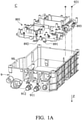
- Fig. 1A shows a portion of a power converter of a first embodiment of the invention.
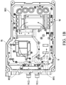
- Fig. 1B shows an inner path of the power converter of the first embodiment of the invention.
- the power converter C of the embodiment of the invention includes a housing 9 and a heat dissipation module 801.
- the housing 9 forms a receiving space 9S.
- the housing 9 comprises a first housing port 911 and a second housing port 912.
- the heat dissipation module 801 is detachably connected to the housing 9, and is adapted to be disposed in the receiving space 9S.
- the heat dissipation module 801 comprises an inner path 8i.
- the inner path 8i communicates the first housing port 911 with the second housing port 912.
- a working fluid W enters the inner path 8i via the first housing port 911, and the working fluid W leaves the inner path 8i via the second housing port 912.
- the heat dissipation module 801 comprises a first inner path port 891 and a second inner path port 892.
- the first inner path port 891 corresponds to the first housing port 911.
- the second inner path port 892 corresponds to the second housing port 912.
- the heat dissipation module 801 is disposed in the housing 9 in a first direction Z.
- the first inner path port 891 is connected to the first housing port 911 in the first direction Z
- the second inner path port 892 is connected to the second housing port 912 in the first direction Z.
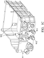
- Fig. 1C shows the details of the housing of the embodiment of the invention.
- the power converter C further comprises a fastening member 921.
- the housing 9 comprises at least one housing fastening portion 922.
- the heat dissipation module 801 comprises at least one module fastening portion 893.
- the fastening member 921 affixes the module fastening portion 893 to the housing fastening portion 922 in the first direction Z.
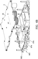
- Fig. 2A is an exploded view of a portion of the power converter of the first embodiment of the invention.
- Fig. 2B is an assembled view of a portion of the power converter of the first embodiment of the invention.
- the power converter C comprises a first circuit board 1.
- the first circuit board 1 includes a first circuit board body 19 and a first heat source 11.
- the first heat source 11 is disposed on the first circuit board body 19.
- the first heat source 11 is thermally connected to the inner path 8i of the heat dissipation module 801.
- the power converter C further comprises a second circuit board 2.
- the second circuit board 2 comprises a second circuit board body 29 and a second heat source 21.
- the second heat source 21 is disposed on the second circuit board body 29.
- the second heat source 21 is thermally connected to the inner path of the heat dissipation module 801.
- the first circuit board 1 is connected to a first side 881 of the heat dissipation module 801.
- the second circuit board 2 is connected to a second side 882 of the heat dissipation module 801, and the first side 881 is opposite to the second side 882.
- Fig. 3A shows the details of the first circuit board and the heat dissipation module of the embodiment of the invention.
- the heat dissipation module 801 comprises a module receiving groove 871.
- the first heat source 11 is disposed in the module receiving groove 871 to be thermally connected to the heat dissipation module 801.
- the first heat source 11 comprises a transformer.
- the first circuit board 1 comprises a capacitor 12.
- the capacitor 12 is connected to the first circuit board body 19.
- the heat dissipation module 801 comprises an annular connection portion 872, and the capacitor 12 is connected to the annular connection portion 872 to be thermally connected to the heat dissipation module.
- the first circuit board 1 further comprises a transistor 13.
- the transistor 13 is connected to the first circuit board body 19.
- the heat dissipation module 801 comprises an elastic sheet 873 and a stopping wall 874.
- the elastic sheet 873 pushes the transistor 13.
- the transistor 13 abuts the stopping wall 874.
- the transistor 13 is thermally connected to the heat dissipation module 801.
- the power converter further comprises a third circuit board 3.
- the third circuit board 3 comprises a third circuit board body 39 and a third heat source 31.
- the third circuit board body 39 comprises a circuit board opening 391.
- the heat dissipation module 801 comprises a (first) module protrusion 875.
- the module protrusion 875 passes through the circuit board opening 391 to be connected to the third heat source 31.
- the third heat source 31 is thus thermally connected to the heat dissipation module 801.
- the third heat source 31 comprises an inductor.
- Figs. 4A and 4B show the details of the second circuit board and the heat dissipation module of the embodiment of the invention.
- the heat dissipation module 801 further comprises another or a (second) module protrusion 876.
- the second heat source 21 is connected to the module protrusion 876.
- the second heat source 21 is thermally connected to the heat dissipation module 801.
- the second heat source 21 is located between the second circuit board body 29 and the heat dissipation module 801.
- the working fluid W enters the inner path 8i via the first housing port 911 and the first inner path port 891.
- the working fluid W removes heat of the heat sources mentioned above from the heat dissipation module 801.
- the working fluid W leaves the inner path 8i via the second inner path port 892, and leaves the power converter via the second housing port 912.
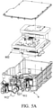
- Fig. 5A is an exploded view of a portion of the power converter of a second embodiment of the invention.
- Fig. 5B is an assembled view of a heat dissipation module of the second embodiment of the invention.
- Fig. 5C is an exploded view of the heat dissipation module of the second embodiment of the invention.
- the heat dissipation module 802 comprises a first module unit 81, a second module unit 82 and a third module unit 83.
- the second module unit 82 overlaps the first module unit 81.
- the third module unit 83 overlaps the first module unit 81.
- the inner path passes through the first module unit 81, the second module unit 82 and the third module unit 83.
- the height of the third module unit 83 relative the first module unit 81 is lower than the height of the second module unit 82 relative the first module unit 81.
- the heat dissipation module 802 comprises a first pipe 841, a second pipe 842 and a third pipe 843.
- the first housing port 911 is connected to the first module unit 81.
- the first pipe 841 connects the first module unit 81 to the second module unit 82.
- the second pipe 842 connects the second module unit 82 to the third module unit 83.
- the third pipe 843 connects the third module unit 83 to the second housing port 912.
- the first module unit 81 comprises a structure notch 811.
- the third pipe 843 passes through the structure notch 811.
- the power converter further comprises a fourth circuit board 41 and a fifth circuit board 42.
- the first circuit board 1 is thermally connected to the first module unit 81.
- the fourth circuit board 41 is thermally connected to the second module unit 82.
- the fifth circuit board 42 is thermally connected to the third module unit 83.
- the working fluid enters the first module unit 81 first. Then, the working fluid passes through the first module unit 81 to enter the second module unit 82 via the first pipe 841. Next, the working fluid passes the second module unit 842 to enter the third module unit 83 via the second pipe 842. Finally, the working fluid leaves the third module unit 83 via the third pipe 843, and therefore leaves the heat dissipation module 802. The working fluid removes heat of the heat sources mentioned above from the heat dissipation module 802.
- the housing and the heat dissipation module are manufactured independently.
- the heat dissipation module can be combined to the first circuit board first, and then be assembled to the housing.
- the heat dissipation space on the heat dissipation module can be sufficiently used due to the segmented assembly process.
- the combination of the first circuit board to the heat dissipation module can be checked. The producing efficiency and reliability of the power converter are improved.
- the circuit board and the heat dissipation module can be combined by welding. The size of the whole power converter is reduced, and the ratio of the metal structure is decreased.
- the welding apparatus and the production line can receive the circuit board and the heat dissipation module easily.
- the space utilization and welding efficiency of the welding apparatus are improved.
- the problem of broken solder can be reduced.
- the solder quality can be easily inspected, and the hardware circuit can be detected and debugged.
- the heat dissipation module can comprise a plurality of module units.
- the module units compose a three-dimensional inner path.
- the heat dissipation area is increased.
- the housing can be made of engineering plastic to reduce weight.
Landscapes
- Engineering & Computer Science (AREA)
- Microelectronics & Electronic Packaging (AREA)
- Physics & Mathematics (AREA)
- Thermal Sciences (AREA)
- Dc-Dc Converters (AREA)
- Cooling Or The Like Of Electrical Apparatus (AREA)
Abstract
A power converter (C) is provided. The power converter includes a housing (9), a heat dissipation module (801), and a first circuit board. The housing forms a receiving space (9S), wherein the housing includes a first housing port (911) and a second housing port (912). The heat dissipation module is detachably connected to the housing, and disposed in the receiving space. The heat dissipation module includes an inner path that communicates the first housing port (911) with the second housing port (912). Working fluid enters the inner path via the first housing port. The working fluid leaves the inner path via the second housing port. The first circuit board includes a first circuit board body and a first heat source, wherein the first heat source is disposed on the first circuit board body, and the first heat source is thermally connected to the inner path of the heat dissipation module.
Description
- This Application claims priority of China Patent Application No.
202010969708.3, filed on Sep. 15, 2020 - The present invention relates to a power converter, and in particular to a power converter with a heat dissipation module.
- The conventional power converter utilizes heat dissipation fins to remove heat. However, the power converter of the electric vehicle generates mass heat, and a water-cooled power converter is required.
- In a conventional water-cooled power converter, the inner path and the housing of the power converter is integrally formed. The size of the housing of the power converter is increased. The welding apparatus and the production line cannot receive the power converter. Additionally, the main structure of the conventional power converter is made of metal, which decreases the temperature of welding, and the solder quality is deteriorated. The main housing has a side wall, and the side wall covers the solder and the hardware, and the solder quality and the hardware cannot be inspected. The conventional coolant channel is integrally formed with the main housing. The coolant channel can only have a two-dimensional design with limited heat dissipation area. The heat dissipation inside the housing cannot be sufficiently used. The heat dissipation structure cannot be modularized, and is unfavorable to the assembly process during mass production.
- Additionally, in different conventional technologies, the solder joint may have residual stress and is easily broken.
- Embodiments of the invention are provided to address the aforementioned difficulty.
- In one embodiment, a power converter is provided. The power converter includes a housing, a heat dissipation module, and a first circuit board. The housing forms a receiving space, wherein the housing comprises a first housing port and a second housing port. The heat dissipation module is detachably connected to the housing, and disposed in the receiving space, wherein the heat dissipation module comprises an inner path, the inner path communicates the first housing port with the second housing port, a working fluid enters the inner path via the first housing port, and the working fluid leaves the inner path via the second housing port. The first circuit board includes a first circuit board body and a first heat source, wherein the first heat source is disposed on the first circuit board body, and the first heat source is thermally connected to the inner path of the heat dissipation module.
- In one embodiment, the heat dissipation module comprises a first inner path port and a second inner path port, the first inner path port corresponds to the first housing port, the second inner path port corresponds to the second housing port, the heat dissipation module is disposed in the housing in a first direction, the first inner path port is connected to the first housing port in the first direction, and the second inner path port is connected to the second housing port in the first direction.
- In one embodiment, the power converter further comprises a fastening member, wherein the housing comprises at least one housing fastening portion, the heat dissipation module comprises at least one module fastening portion, and the fastening member affixes the module fastening portion to the housing fastening portion in the first direction.
- In one embodiment, the power converter further comprises a second circuit board, wherein the second circuit board comprises a second circuit board body and a second heat source, the second heat source is disposed on the second circuit board body, and the second heat source is thermally connected to the inner path of the heat dissipation module, the first circuit board is connected to the first side of the heat dissipation module, the second circuit board is connected to the second side of the heat dissipation module, and the first side is opposite to the second side.
- In one embodiment, the heat dissipation module comprises a module receiving groove, and the first heat source is disposed in the module receiving groove to be thermally connected to the heat dissipation module.
- In one embodiment, the first heat source comprises a transformer.
- In one embodiment, the first circuit board comprises a capacitor, the capacitor is connected to the first circuit board body, the heat dissipation module comprises an annular connection portion, and the capacitor is connected to the annular connection portion to be thermally connected to the heat dissipation module.
- In one embodiment, the first circuit board further comprises a transistor, the transistor is connected to the first circuit board body, the heat dissipation module comprises an elastic sheet and a stopping wall, the elastic sheet pushes the transistor, the transistor abuts the stopping wall, and the transistor is thermally connected to the heat dissipation module.
- In one embodiment, the power converter further comprises a third circuit board, wherein the third circuit board comprises a third circuit board body and a third heat source, the third circuit board body comprises a circuit board opening, the heat dissipation module comprises a module protrusion, the module protrusion passes through the circuit board opening to be connected to the third heat source.
- In one embodiment, the third heat source comprises an inductor.
- In one embodiment, the heat dissipation module further comprises a module protrusion, the second heat source is connected to the module protrusion, and the second heat source is thermally connected to the heat dissipation module, and the second heat source is located between the second circuit board body and the heat dissipation module.
- In one embodiment, the heat dissipation module comprises a first module unit, a second module unit, and a third module unit, the second module unit overlaps the first module unit, the third module unit overlaps the first module unit, the inner path passes through the first module unit, the second module unit, and the third module unit.
- In one embodiment, the height of the third module unit relative the first module unit is lower than the height of the second module unit relative the first module unit.
- In one embodiment, the working fluid enters the first module unit first; then, the working fluid passes through the first module unit to enter the second module unit; next, the working fluid passes the second module unit to enter the third module unit; and finally the working fluid leaves the third module unit.
- In one embodiment, the heat dissipation module comprises a first pipe, a second pipe, and a third pipe, the first housing port is connected to the first module unit, the first pipe connects the first module unit to the second module unit, the second pipe connects the second module unit to the third module unit, and the third pipe connects the third module unit to the second housing port.
- In one embodiment, the first module unit comprises a structure notch, and the third pipe passes through the structure notch.
- In one embodiment, the power converter further comprises a fourth circuit board and a fifth circuit board, wherein the first circuit board is thermally connected to the first module unit, the fourth circuit board is thermally connected to the second module unit, and the fifth circuit board is thermally connected to the third module unit.
- In one embodiment, an electric vehicle is provided. The electric vehicle includes a cooling system and a power converter. A working fluid flows cyclically through the cooling system to transmit heat. The power converter includes a housing, a heat dissipation module, and a first circuit board. The housing forms a receiving space, wherein the housing comprises a first housing port and a second housing port. The heat dissipation module is detachably connected to the housing, and disposed in the receiving space, wherein the heat dissipation module comprises an inner path, the inner path communicates the first housing port with the second housing port, the working fluid enters the inner path via the first housing port, and the working fluid leaves the inner path via the second housing port. The first circuit board comprises a first circuit board body and a first heat source, wherein the first heat source is disposed on the first circuit board body, and the first heat source is thermally connected to the inner path of the heat dissipation module.
- In the power converter of the embodiments of the invention, the housing and the heat dissipation module are manufactured independently. The heat dissipation module can be combined to the first circuit board first, and then be assembled to the housing. The heat dissipation space on the heat dissipation module can be sufficiently used due to the segmented assembly process. After the heat dissipation module is assembled to the housing, the combination of the first circuit board to the heat dissipation module can be checked. The producing efficiency and reliability of the power converter are improved. Additionally, the circuit board and the heat dissipation module can be combined by welding. The size of the whole power converter is reduced, and the ratio of the metal structure is decreased. Compared to the convention art, the welding apparatus and the production line can receive the circuit board and the heat dissipation module easily. The space utilization and welding efficiency of the welding apparatus are improved. The problem of broken solder can be reduced. The solder quality can be easily inspected, and the hardware circuit can be detected and debugged.
- Additionally, in another embodiment, the heat dissipation module can comprises a plurality of module units. The module units compose a three-dimensional inner path. The heat dissipation area is increased. In another embodiment, the housing can be made of engineering plastic to reduce weight.
- A detailed description is given in the following embodiments with reference to the accompanying drawings.
- The present invention can be more fully understood by reading the subsequent detailed description and examples with references made to the accompanying drawings, wherein:
-
Fig. 1A shows a portion of a power converter of a first embodiment of the invention; -
Fig. 1B shows an inner path of the power converter of the first embodiment of the invention; -
Fig. 1C shows the details of the housing of the embodiment of the invention; -
Fig. 2A is an exploded view of a portion of the power converter of the first embodiment of the invention; -
Fig. 2B is an assembled view of a portion of the power converter of the first embodiment of the invention; -
Fig. 3A shows the details of the first circuit board and the heat dissipation module of the embodiment of the invention; -
Figs. 3B and3C show the details of the third circuit board and the heat dissipation module of the embodiment of the invention; -
Figs. 4A and4B show the details of the second circuit board and the heat dissipation module of the embodiment of the invention; -
Fig. 5A is an exploded view of a portion of the power converter of a second embodiment of the invention; -
Fig. 5B is an assembled view of a heat dissipation module of the second embodiment of the invention; and -
Fig. 5C is an exploded view of the heat dissipation module of the second embodiment of the invention. - The following description is of the best-contemplated mode of carrying out the invention. This description is made for the purpose of illustrating the general principles of the invention and should not be taken in a limiting sense. The scope of the invention is best determined by reference to the appended claims.
-
Fig. 1A shows a portion of a power converter of a first embodiment of the invention.Fig. 1B shows an inner path of the power converter of the first embodiment of the invention. With reference toFigs. 1A and1B , the power converter C of the embodiment of the invention includes ahousing 9 and aheat dissipation module 801. Thehousing 9 forms a receivingspace 9S. Thehousing 9 comprises afirst housing port 911 and asecond housing port 912. Theheat dissipation module 801 is detachably connected to thehousing 9, and is adapted to be disposed in the receivingspace 9S. Theheat dissipation module 801 comprises aninner path 8i. Theinner path 8i communicates thefirst housing port 911 with thesecond housing port 912. A working fluid W enters theinner path 8i via thefirst housing port 911, and the working fluid W leaves theinner path 8i via thesecond housing port 912. - With reference to
Figs. 1A and1B , in one embodiment, theheat dissipation module 801 comprises a firstinner path port 891 and a secondinner path port 892. The firstinner path port 891 corresponds to thefirst housing port 911. The secondinner path port 892 corresponds to thesecond housing port 912. Theheat dissipation module 801 is disposed in thehousing 9 in a first direction Z. The firstinner path port 891 is connected to thefirst housing port 911 in the first direction Z, and the secondinner path port 892 is connected to thesecond housing port 912 in the first direction Z. -
Fig. 1C shows the details of the housing of the embodiment of the invention. With reference toFigs. 1A and1C , in one embodiment, the power converter C further comprises afastening member 921. Thehousing 9 comprises at least onehousing fastening portion 922. Theheat dissipation module 801 comprises at least onemodule fastening portion 893. Thefastening member 921 affixes themodule fastening portion 893 to thehousing fastening portion 922 in the first direction Z. -
Fig. 2A is an exploded view of a portion of the power converter of the first embodiment of the invention.Fig. 2B is an assembled view of a portion of the power converter of the first embodiment of the invention. With reference toFigs. 2A and2B , in one embodiment, the power converter C comprises afirst circuit board 1. Thefirst circuit board 1 includes a firstcircuit board body 19 and afirst heat source 11. Thefirst heat source 11 is disposed on the firstcircuit board body 19. Thefirst heat source 11 is thermally connected to theinner path 8i of theheat dissipation module 801. - With reference to
Figs. 2A and2B , in one embodiment, the power converter C further comprises asecond circuit board 2. Thesecond circuit board 2 comprises a secondcircuit board body 29 and asecond heat source 21. Thesecond heat source 21 is disposed on the secondcircuit board body 29. Thesecond heat source 21 is thermally connected to the inner path of theheat dissipation module 801. Thefirst circuit board 1 is connected to afirst side 881 of theheat dissipation module 801. Thesecond circuit board 2 is connected to asecond side 882 of theheat dissipation module 801, and thefirst side 881 is opposite to thesecond side 882. -
Fig. 3A shows the details of the first circuit board and the heat dissipation module of the embodiment of the invention. With reference toFig. 3A , in one embodiment, theheat dissipation module 801 comprises amodule receiving groove 871. Thefirst heat source 11 is disposed in themodule receiving groove 871 to be thermally connected to theheat dissipation module 801. In one embodiment, thefirst heat source 11 comprises a transformer. - With reference to
Fig. 3A , in one embodiment, thefirst circuit board 1 comprises acapacitor 12. Thecapacitor 12 is connected to the firstcircuit board body 19. Theheat dissipation module 801 comprises anannular connection portion 872, and thecapacitor 12 is connected to theannular connection portion 872 to be thermally connected to the heat dissipation module. - With reference to
Fig. 3A , in one embodiment, thefirst circuit board 1 further comprises atransistor 13. Thetransistor 13 is connected to the firstcircuit board body 19. Theheat dissipation module 801 comprises anelastic sheet 873 and a stoppingwall 874. Theelastic sheet 873 pushes thetransistor 13. Thetransistor 13 abuts the stoppingwall 874. Thetransistor 13 is thermally connected to theheat dissipation module 801. -
Figs. 3B and3C show the details of the third circuit board and the heat dissipation module of the embodiment of the invention. With reference toFigs. 3B and3C , in one embodiment, the power converter further comprises athird circuit board 3. Thethird circuit board 3 comprises a thirdcircuit board body 39 and athird heat source 31. The thirdcircuit board body 39 comprises acircuit board opening 391. Theheat dissipation module 801 comprises a (first)module protrusion 875. Themodule protrusion 875 passes through the circuit board opening 391 to be connected to thethird heat source 31. Thethird heat source 31 is thus thermally connected to theheat dissipation module 801. In one embodiment, thethird heat source 31 comprises an inductor. -
Figs. 4A and4B show the details of the second circuit board and the heat dissipation module of the embodiment of the invention. With reference toFigs. 4A and4B , in one embodiment, theheat dissipation module 801 further comprises another or a (second)module protrusion 876. Thesecond heat source 21 is connected to themodule protrusion 876. Thesecond heat source 21 is thermally connected to theheat dissipation module 801. Thesecond heat source 21 is located between the secondcircuit board body 29 and theheat dissipation module 801. - With reference to
Fig. 1B , in the first embodiment, the working fluid W enters theinner path 8i via thefirst housing port 911 and the firstinner path port 891. When the working fluid W travels in theinner path 8i, the working fluid W removes heat of the heat sources mentioned above from theheat dissipation module 801. The working fluid W leaves theinner path 8i via the secondinner path port 892, and leaves the power converter via thesecond housing port 912. -
Fig. 5A is an exploded view of a portion of the power converter of a second embodiment of the invention.Fig. 5B is an assembled view of a heat dissipation module of the second embodiment of the invention.Fig. 5C is an exploded view of the heat dissipation module of the second embodiment of the invention. With reference toFigs. 5A ,5B and5C , in the second embodiment of the invention, theheat dissipation module 802 comprises afirst module unit 81, asecond module unit 82 and athird module unit 83. Thesecond module unit 82 overlaps thefirst module unit 81. Thethird module unit 83 overlaps thefirst module unit 81. The inner path passes through thefirst module unit 81, thesecond module unit 82 and thethird module unit 83. - With reference to
Figs. 5A ,5B and5C , in one embodiment, the height of thethird module unit 83 relative thefirst module unit 81 is lower than the height of thesecond module unit 82 relative thefirst module unit 81. - With reference to
Figs. 5A ,5B and5C , in one embodiment, theheat dissipation module 802 comprises afirst pipe 841, asecond pipe 842 and athird pipe 843. Thefirst housing port 911 is connected to thefirst module unit 81. Thefirst pipe 841 connects thefirst module unit 81 to thesecond module unit 82. Thesecond pipe 842 connects thesecond module unit 82 to thethird module unit 83. Thethird pipe 843 connects thethird module unit 83 to thesecond housing port 912. - With reference to
Figs. 5A ,5B and5C , in one embodiment, thefirst module unit 81 comprises astructure notch 811. Thethird pipe 843 passes through thestructure notch 811. - With reference to
Figs. 5A ,5B and5C , in one embodiment, the power converter further comprises afourth circuit board 41 and afifth circuit board 42. Thefirst circuit board 1 is thermally connected to thefirst module unit 81. Thefourth circuit board 41 is thermally connected to thesecond module unit 82. Thefifth circuit board 42 is thermally connected to thethird module unit 83. - With reference to
Figs. 5A ,5B and5C , in one embodiment, the working fluid (not shown) enters thefirst module unit 81 first. Then, the working fluid passes through thefirst module unit 81 to enter thesecond module unit 82 via thefirst pipe 841. Next, the working fluid passes thesecond module unit 842 to enter thethird module unit 83 via thesecond pipe 842. Finally, the working fluid leaves thethird module unit 83 via thethird pipe 843, and therefore leaves theheat dissipation module 802. The working fluid removes heat of the heat sources mentioned above from theheat dissipation module 802. - In the power converter of the embodiments of the invention, the housing and the heat dissipation module are manufactured independently. The heat dissipation module can be combined to the first circuit board first, and then be assembled to the housing. The heat dissipation space on the heat dissipation module can be sufficiently used due to the segmented assembly process. After the heat dissipation module is assembled to the housing, the combination of the first circuit board to the heat dissipation module can be checked. The producing efficiency and reliability of the power converter are improved. Additionally, the circuit board and the heat dissipation module can be combined by welding. The size of the whole power converter is reduced, and the ratio of the metal structure is decreased. Compared to the convention art, the welding apparatus and the production line can receive the circuit board and the heat dissipation module easily. The space utilization and welding efficiency of the welding apparatus are improved. The problem of broken solder can be reduced. The solder quality can be easily inspected, and the hardware circuit can be detected and debugged.
- Additionally, in another embodiment, the heat dissipation module can comprise a plurality of module units. The module units compose a three-dimensional inner path. The heat dissipation area is increased. In another embodiment, the housing can be made of engineering plastic to reduce weight.
- Use of ordinal terms such as "first", "second", "third", etc., in the claims to modify a claim element does not by itself connote any priority, precedence, or order of one claim element over another or the temporal order in which acts of a method are performed, but are used merely as labels to distinguish one claim element having a certain name from another element having the same name (but for use of the ordinal term).
- While the invention has been described by way of example and in terms of the preferred embodiments, it should be understood that the invention is not limited to the disclosed embodiments. On the contrary, it is intended to cover various modifications and similar arrangements (as would be apparent to those skilled in the art). Therefore, the scope of the appended claims should be accorded the broadest interpretation so as to encompass all such modifications and similar arrangements.
Claims (18)
- A power converter (C), comprising:a housing (9), forming a receiving space (9S), wherein the housing comprises a first housing port (911) and a second housing port (912);a heat dissipation module (801), detachably connected to the housing, and disposed in the receiving space, wherein the heat dissipation module comprises an inner path (8i), the inner path communicates the first housing port with the second housing port, a working fluid (W) enters the inner path via the first housing port (911), and the working fluid leaves the inner path via the second housing port (912); anda first circuit board (1), comprising a first circuit board body (19) and a first heat source (11), wherein the first heat source is disposed on the first circuit board body, and the first heat source is thermally connected to the inner path of the heat dissipation module.
- The power converter (C) as claimed in claim 1, wherein the heat dissipation module (801) comprises a first inner path port (891) and a second inner path port (892), the first inner path port corresponds to the first housing port (911), the second inner path port corresponds to the second housing port (912), the heat dissipation module is disposed in the housing in a first direction (Z), the first inner path port is connected to the first housing port in the first direction, and the second inner path port is connected to the second housing port in the first direction.
- The power converter (C) as claimed in claim 2, further comprising a fastening member (921), wherein the housing comprises at least one housing fastening portion (922), the heat dissipation module comprises at least one module fastening portion (893), and the fastening member affixes the module fastening portion to the housing fastening portion in the first direction (Z).
- The power converter (C) as claimed in one of the preceding claims, further comprising a second circuit board (2), wherein the second circuit board comprises a second circuit board body (29) and a second heat source (21), the second heat source is disposed on the second circuit board body, and the second heat source is thermally connected to the inner path (8i) of the heat dissipation module, the first circuit board (1) is connected to a first side (881) of the heat dissipation module, the second circuit board (2) is connected to a second side (882) of the heat dissipation module, and the first side is opposite to the second side.
- The power converter (C) as claimed in one of the preceding claims, wherein the heat dissipation module comprises a module receiving groove (871), and the first heat source (11) is disposed in the module receiving groove to be thermally connected to the heat dissipation module.
- The power converter (C) as claimed in one of the preceding claims, wherein the first heat source (11) comprises a transformer.
- The power converter (C) as claimed in one of the preceding claims, wherein the first circuit board (1) comprises a capacitor (12), the capacitor is connected to the first circuit board body, the heat dissipation module comprises an annular connection portion (872), and the capacitor is connected to the annular connection portion to be thermally connected to the heat dissipation module.
- The power converter (C) as claimed in one of the preceding claims, wherein the first circuit board (1) further comprises a transistor (13), the transistor is connected to the first circuit board body, the heat dissipation module comprises an elastic sheet (873) and a stopping wall (874), the elastic sheet pushes the transistor, the transistor abuts the stopping wall, and the transistor is thermally connected to the heat dissipation module.
- The power converter (C) as claimed in claim 4, further comprising a third circuit board (3), wherein the third circuit board comprises a third circuit board body (39) and a third heat source (31), the third circuit board body comprises a circuit board opening (391), the heat dissipation module comprises a module protrusion (875), the module protrusion passes through the circuit board opening to be connected to the third heat source.
- The power converter (C) as claimed in claim 9, wherein the third heat source (31) comprises an inductor.
- The power converter (C) as claimed in claim 4, wherein the heat dissipation module further comprises a module protrusion (876), the second heat source (21) is connected to the module protrusion, and the second heat source is thermally connected to the heat dissipation module, and the second heat source is located between the second circuit board body and the heat dissipation module.
- The power converter as claimed in one of the preceding claims, wherein the heat dissipation module comprises a first module unit (81), a second module unit (82), and a third module unit (83), the second module unit overlaps the first module unit, the third module unit overlaps the first module unit, the inner path passes through the first module unit, the second module unit, and the third module unit.
- The power converter (C) as claimed in claim 12, wherein a height of the third module unit (83) relative the first module unit (81) is lower than a height of the second module unit (82) relative the first module unit.
- The power converter (C) as claimed in claim 12 or 13, wherein the working fluid (W) enters the first module unit (81) first; then, the working fluid passes through the first module unit to enter the second module unit (82); next, the working fluid passes the second module unit to enter the third module unit (83); and finally the working fluid leaves the third module unit.
- The power converter (C) as claimed in claim 14, wherein the heat dissipation module comprises a first pipe (841), a second pipe (842), and a third pipe (843), the first housing port (911) is connected to the first module unit, the first pipe connects the first module unit to the second module unit, the second pipe connects the second module unit to the third module unit, and the third pipe connects the third module unit to the second housing port (912).
- The power converter (C) as claimed in claim 15, wherein the first module unit comprises a structure notch (811), and the third pipe (843) passes through the structure notch.
- The power converter (C) as claimed in claim 12, further comprising a fourth circuit board (41) and a fifth circuit board (42), wherein the first circuit board (1) is thermally connected to the first module unit (81), the fourth circuit board (41) is thermally connected to the second module unit (82), and the fifth circuit board (42) is thermally connected to the third module unit (83).
- An electric vehicle, comprising:a cooling system, wherein a working fluid (W) flows cyclically through the cooling system to transmit heat; anda power converter (C), comprising:a housing (9), forming a receiving space (9S), wherein the housing comprises a first housing port (911) and a second housing port (912);a heat dissipation module (801), detachably connected to the housing, and disposed in the receiving space, wherein the heat dissipation module comprises an inner path (8i), the inner path communicates the first housing port with the second housing port, the working fluid (W) enters the inner path via the first housing port (911), and the working fluid leaves the inner path via the second housing port (912); anda first circuit board (1), comprising a first circuit board body (19) and a first heat source (11), wherein the first heat source is disposed on the first circuit board body, and the first heat source is thermally connected to the inner path of the heat dissipation module.
Applications Claiming Priority (1)
| Application Number | Priority Date | Filing Date | Title |
|---|---|---|---|
| CN202010969708.3A CN114268212B (en) | 2020-09-15 | 2020-09-15 | Power converter |
Publications (1)
| Publication Number | Publication Date |
|---|---|
| EP3968746A1 true EP3968746A1 (en) | 2022-03-16 |
Family
ID=75562530
Family Applications (1)
| Application Number | Title | Priority Date | Filing Date |
|---|---|---|---|
| EP21168536.7A Withdrawn EP3968746A1 (en) | 2020-09-15 | 2021-04-15 | Electric vehicle and power converter thereof |
Country Status (3)
| Country | Link |
|---|---|
| US (2) | US11547026B2 (en) |
| EP (1) | EP3968746A1 (en) |
| CN (1) | CN114268212B (en) |
Cited By (1)
| Publication number | Priority date | Publication date | Assignee | Title |
|---|---|---|---|---|
| WO2025002598A1 (en) * | 2023-06-28 | 2025-01-02 | Vitesco Technologies GmbH | High-voltage power box for an electrically driven vehicle |
Families Citing this family (2)
| Publication number | Priority date | Publication date | Assignee | Title |
|---|---|---|---|---|
| CN117529007A (en) * | 2022-07-28 | 2024-02-06 | 比亚迪半导体股份有限公司 | Power modules, inverters, motor controllers and vehicles |
| CN221008935U (en) * | 2023-08-24 | 2024-05-24 | 法雷奥新能源汽车(深圳)有限公司 | Heat sink, power device module and vehicle |
Citations (5)
| Publication number | Priority date | Publication date | Assignee | Title |
|---|---|---|---|---|
| JP2012120381A (en) * | 2010-12-02 | 2012-06-21 | Fuji Electric Co Ltd | Electric power conversion system and electric drive vehicle using the same |
| US20130223011A1 (en) * | 2012-02-24 | 2013-08-29 | Delta Electronics (Shanghai) Co., Ltd. | Power converter device |
| US20150146375A1 (en) * | 2013-11-26 | 2015-05-28 | Delta Electronics (Shanghai) Co., Ltd. | Power conversion device and power conversion assembly |
| US20160128236A1 (en) * | 2014-11-04 | 2016-05-05 | Ge Aviation Systems Llc | Power converter assembly |
| KR102077670B1 (en) * | 2019-11-11 | 2020-02-14 | 고등기술연구원연구조합 | Cooling Structure of Integrated Power Converting Apparatus for Electric Vehicles |
Family Cites Families (15)
| Publication number | Priority date | Publication date | Assignee | Title |
|---|---|---|---|---|
| TWI365704B (en) | 2009-03-16 | 2012-06-01 | Silitek Electronic Guangzhou | Waterproof and heat-dissipating structure mounted on electronic device |
| US8081463B2 (en) * | 2009-06-16 | 2011-12-20 | Asia Vital Components Co., Ltd. | Water-cooled communication chassis |
| TWI394524B (en) | 2010-02-10 | 2013-04-21 | Delta Electronics Inc | Modularized heat dissipating apparatus |
| CN102159051B (en) | 2010-02-12 | 2013-05-01 | 台达电子工业股份有限公司 | Modular Cooling Unit |
| US8363412B2 (en) * | 2010-03-25 | 2013-01-29 | Ixys Corporation | Mother and daughter board configuration to improve current and voltage capabilities of a power instrument |
| EP2557907B1 (en) * | 2011-08-11 | 2013-12-18 | Siemens Aktiengesellschaft | Cooling assembly for cooling a frequency converter module |
| US10164373B1 (en) * | 2013-03-15 | 2018-12-25 | Koolance, Inc. | Automatic engagement system for liquid or power connections |
| CN203840188U (en) * | 2014-05-08 | 2014-09-17 | 安徽江淮汽车股份有限公司 | Integrated structure of drive controller and DC (direct current) converter |
| CN105025691B (en) | 2015-08-10 | 2018-03-06 | 苏州大景能源科技有限公司 | A kind of electronic installation, heat abstractor and its cooling means using liquid-cooling heat radiation |
| CN106655806B (en) * | 2015-10-29 | 2019-02-26 | 台达电子企业管理(上海)有限公司 | Power supply change-over device |
| FR3087617B1 (en) * | 2018-10-17 | 2023-10-27 | Valeo Systemes De Controle Moteur | ELECTRONIC EQUIPMENT FOR VEHICLES |
| TWM589961U (en) | 2018-10-24 | 2020-01-21 | 迎廣科技股份有限公司 | Heat exchange device and liquid cooling heat dissipation system with the heat exchange device |
| CN209472933U (en) | 2018-10-29 | 2019-10-08 | 东风航盛(武汉)汽车控制系统有限公司 | A kind of cooling water channel structure of motor controller of new energy automobile |
| KR102119768B1 (en) * | 2018-11-21 | 2020-06-05 | 현대오트론 주식회사 | Cooling structure for radiate heat element |
| CN109413958B (en) | 2018-12-03 | 2023-11-21 | 浙江富特科技股份有限公司 | Vehicle charger device and automobile |
-
2020
- 2020-09-15 CN CN202010969708.3A patent/CN114268212B/en active Active
-
2021
- 2021-04-01 US US17/220,092 patent/US11547026B2/en active Active
- 2021-04-15 EP EP21168536.7A patent/EP3968746A1/en not_active Withdrawn
-
2022
- 2022-11-16 US US17/987,963 patent/US12207451B2/en active Active
Patent Citations (5)
| Publication number | Priority date | Publication date | Assignee | Title |
|---|---|---|---|---|
| JP2012120381A (en) * | 2010-12-02 | 2012-06-21 | Fuji Electric Co Ltd | Electric power conversion system and electric drive vehicle using the same |
| US20130223011A1 (en) * | 2012-02-24 | 2013-08-29 | Delta Electronics (Shanghai) Co., Ltd. | Power converter device |
| US20150146375A1 (en) * | 2013-11-26 | 2015-05-28 | Delta Electronics (Shanghai) Co., Ltd. | Power conversion device and power conversion assembly |
| US20160128236A1 (en) * | 2014-11-04 | 2016-05-05 | Ge Aviation Systems Llc | Power converter assembly |
| KR102077670B1 (en) * | 2019-11-11 | 2020-02-14 | 고등기술연구원연구조합 | Cooling Structure of Integrated Power Converting Apparatus for Electric Vehicles |
Cited By (1)
| Publication number | Priority date | Publication date | Assignee | Title |
|---|---|---|---|---|
| WO2025002598A1 (en) * | 2023-06-28 | 2025-01-02 | Vitesco Technologies GmbH | High-voltage power box for an electrically driven vehicle |
Also Published As
| Publication number | Publication date |
|---|---|
| US11547026B2 (en) | 2023-01-03 |
| US12207451B2 (en) | 2025-01-21 |
| US20230070726A1 (en) | 2023-03-09 |
| CN114268212A (en) | 2022-04-01 |
| CN114268212B (en) | 2025-07-22 |
| US20220087077A1 (en) | 2022-03-17 |
Similar Documents
| Publication | Publication Date | Title |
|---|---|---|
| US12207451B2 (en) | Electric vehicle and power converter thereof | |
| KR100612810B1 (en) | Electronic appliance | |
| US11150028B2 (en) | Cooling device with superimposed fin groups and parallel heatpipes | |
| US7180736B2 (en) | Microelectronic package within cylindrical housing | |
| US7316263B2 (en) | Cold plate | |
| US20200187385A1 (en) | Power module with integrated cooling device | |
| US20150338079A1 (en) | Lighting device with at least one semiconductor light source | |
| EP3396776A1 (en) | Battery system | |
| US20160073556A1 (en) | Electric Power Convertor | |
| US9949405B2 (en) | Electrical device | |
| JP2017112768A (en) | Power converter | |
| US11071233B1 (en) | Auxiliary-cooled electronics assembly with extruded cooling cavity | |
| US11076503B2 (en) | Thermally conductive insert element for electronic unit | |
| JP2010087002A (en) | Heating component cooling structure | |
| US20160219758A1 (en) | Electric power convertor | |
| US20120234021A1 (en) | Heat exchanger | |
| JP2006005014A (en) | Stacked cooler | |
| JP6775374B2 (en) | Manufacturing method of heat dissipation unit | |
| US11432440B2 (en) | Power conversion apparatus | |
| JP2017183621A (en) | Electronics | |
| CN102537305A (en) | Fixed electronic transmission control module | |
| CN116458274A (en) | Liquid cooling body, in particular for cooling power electronics components | |
| US11324148B2 (en) | Cooling system for power modules | |
| US20240401891A1 (en) | Joint unit | |
| EP3290850A1 (en) | Lattice boiler evaporator |
Legal Events
| Date | Code | Title | Description |
|---|---|---|---|
| PUAI | Public reference made under article 153(3) epc to a published international application that has entered the european phase |
Free format text: ORIGINAL CODE: 0009012 |
|
| STAA | Information on the status of an ep patent application or granted ep patent |
Free format text: STATUS: THE APPLICATION HAS BEEN PUBLISHED |
|
| AK | Designated contracting states |
Kind code of ref document: A1 Designated state(s): AL AT BE BG CH CY CZ DE DK EE ES FI FR GB GR HR HU IE IS IT LI LT LU LV MC MK MT NL NO PL PT RO RS SE SI SK SM TR |
|
| STAA | Information on the status of an ep patent application or granted ep patent |
Free format text: STATUS: THE APPLICATION IS DEEMED TO BE WITHDRAWN |
|
| 18D | Application deemed to be withdrawn |
Effective date: 20220917 |