EP3968631A1 - Anordnung eines optischen projektionssystems zur anwendung an und/ oder in fahrzeugen - Google Patents
Anordnung eines optischen projektionssystems zur anwendung an und/ oder in fahrzeugen Download PDFInfo
- Publication number
- EP3968631A1 EP3968631A1 EP21000256.4A EP21000256A EP3968631A1 EP 3968631 A1 EP3968631 A1 EP 3968631A1 EP 21000256 A EP21000256 A EP 21000256A EP 3968631 A1 EP3968631 A1 EP 3968631A1
- Authority
- EP
- European Patent Office
- Prior art keywords
- light
- module
- vehicle
- projection
- arrangement according
- Prior art date
- Legal status (The legal status is an assumption and is not a legal conclusion. Google has not performed a legal analysis and makes no representation as to the accuracy of the status listed.)
- Withdrawn
Links
Images





Classifications
-
- B—PERFORMING OPERATIONS; TRANSPORTING
- B60—VEHICLES IN GENERAL
- B60K—ARRANGEMENT OR MOUNTING OF PROPULSION UNITS OR OF TRANSMISSIONS IN VEHICLES; ARRANGEMENT OR MOUNTING OF PLURAL DIVERSE PRIME-MOVERS IN VEHICLES; AUXILIARY DRIVES FOR VEHICLES; INSTRUMENTATION OR DASHBOARDS FOR VEHICLES; ARRANGEMENTS IN CONNECTION WITH COOLING, AIR INTAKE, GAS EXHAUST OR FUEL SUPPLY OF PROPULSION UNITS IN VEHICLES
- B60K35/00—Instruments specially adapted for vehicles; Arrangement of instruments in or on vehicles
- B60K35/20—Output arrangements, i.e. from vehicle to user, associated with vehicle functions or specially adapted therefor
- B60K35/28—Output arrangements, i.e. from vehicle to user, associated with vehicle functions or specially adapted therefor characterised by the type of the output information, e.g. video entertainment or vehicle dynamics information; characterised by the purpose of the output information, e.g. for attracting the attention of the driver
-
- G—PHYSICS
- G02—OPTICS
- G02B—OPTICAL ELEMENTS, SYSTEMS OR APPARATUS
- G02B27/00—Optical systems or apparatus not provided for by any of the groups G02B1/00 - G02B26/00, G02B30/00
- G02B27/01—Head-up displays
- G02B27/0149—Head-up displays characterised by mechanical features
-
- B—PERFORMING OPERATIONS; TRANSPORTING
- B60—VEHICLES IN GENERAL
- B60K—ARRANGEMENT OR MOUNTING OF PROPULSION UNITS OR OF TRANSMISSIONS IN VEHICLES; ARRANGEMENT OR MOUNTING OF PLURAL DIVERSE PRIME-MOVERS IN VEHICLES; AUXILIARY DRIVES FOR VEHICLES; INSTRUMENTATION OR DASHBOARDS FOR VEHICLES; ARRANGEMENTS IN CONNECTION WITH COOLING, AIR INTAKE, GAS EXHAUST OR FUEL SUPPLY OF PROPULSION UNITS IN VEHICLES
- B60K35/00—Instruments specially adapted for vehicles; Arrangement of instruments in or on vehicles
- B60K35/50—Instruments characterised by their means of attachment to or integration in the vehicle
-
- B—PERFORMING OPERATIONS; TRANSPORTING
- B60—VEHICLES IN GENERAL
- B60K—ARRANGEMENT OR MOUNTING OF PROPULSION UNITS OR OF TRANSMISSIONS IN VEHICLES; ARRANGEMENT OR MOUNTING OF PLURAL DIVERSE PRIME-MOVERS IN VEHICLES; AUXILIARY DRIVES FOR VEHICLES; INSTRUMENTATION OR DASHBOARDS FOR VEHICLES; ARRANGEMENTS IN CONNECTION WITH COOLING, AIR INTAKE, GAS EXHAUST OR FUEL SUPPLY OF PROPULSION UNITS IN VEHICLES
- B60K35/00—Instruments specially adapted for vehicles; Arrangement of instruments in or on vehicles
- B60K35/60—Instruments characterised by their location or relative disposition in or on vehicles
-
- B—PERFORMING OPERATIONS; TRANSPORTING
- B60—VEHICLES IN GENERAL
- B60Q—ARRANGEMENT OF SIGNALLING OR LIGHTING DEVICES, THE MOUNTING OR SUPPORTING THEREOF OR CIRCUITS THEREFOR, FOR VEHICLES IN GENERAL
- B60Q1/00—Arrangement of optical signalling or lighting devices, the mounting or supporting thereof or circuits therefor
- B60Q1/0011—Arrangement of optical signalling or lighting devices, the mounting or supporting thereof or circuits therefor with light guides for distributing the light between several lighting or signalling devices
-
- B—PERFORMING OPERATIONS; TRANSPORTING
- B60—VEHICLES IN GENERAL
- B60Q—ARRANGEMENT OF SIGNALLING OR LIGHTING DEVICES, THE MOUNTING OR SUPPORTING THEREOF OR CIRCUITS THEREFOR, FOR VEHICLES IN GENERAL
- B60Q1/00—Arrangement of optical signalling or lighting devices, the mounting or supporting thereof or circuits therefor
- B60Q1/0029—Spatial arrangement
- B60Q1/0035—Spatial arrangement relative to the vehicle
-
- B—PERFORMING OPERATIONS; TRANSPORTING
- B60—VEHICLES IN GENERAL
- B60Q—ARRANGEMENT OF SIGNALLING OR LIGHTING DEVICES, THE MOUNTING OR SUPPORTING THEREOF OR CIRCUITS THEREFOR, FOR VEHICLES IN GENERAL
- B60Q1/00—Arrangement of optical signalling or lighting devices, the mounting or supporting thereof or circuits therefor
- B60Q1/0088—Details of electrical connections
-
- B—PERFORMING OPERATIONS; TRANSPORTING
- B60—VEHICLES IN GENERAL
- B60Q—ARRANGEMENT OF SIGNALLING OR LIGHTING DEVICES, THE MOUNTING OR SUPPORTING THEREOF OR CIRCUITS THEREFOR, FOR VEHICLES IN GENERAL
- B60Q1/00—Arrangement of optical signalling or lighting devices, the mounting or supporting thereof or circuits therefor
- B60Q1/26—Arrangement of optical signalling or lighting devices, the mounting or supporting thereof or circuits therefor the devices being primarily intended to indicate the vehicle, or parts thereof, or to give signals, to other traffic
- B60Q1/2661—Arrangement of optical signalling or lighting devices, the mounting or supporting thereof or circuits therefor the devices being primarily intended to indicate the vehicle, or parts thereof, or to give signals, to other traffic mounted on parts having other functions
- B60Q1/2665—Arrangement of optical signalling or lighting devices, the mounting or supporting thereof or circuits therefor the devices being primarily intended to indicate the vehicle, or parts thereof, or to give signals, to other traffic mounted on parts having other functions on rear-view mirrors
-
- B—PERFORMING OPERATIONS; TRANSPORTING
- B60—VEHICLES IN GENERAL
- B60Q—ARRANGEMENT OF SIGNALLING OR LIGHTING DEVICES, THE MOUNTING OR SUPPORTING THEREOF OR CIRCUITS THEREFOR, FOR VEHICLES IN GENERAL
- B60Q1/00—Arrangement of optical signalling or lighting devices, the mounting or supporting thereof or circuits therefor
- B60Q1/26—Arrangement of optical signalling or lighting devices, the mounting or supporting thereof or circuits therefor the devices being primarily intended to indicate the vehicle, or parts thereof, or to give signals, to other traffic
- B60Q1/32—Arrangement of optical signalling or lighting devices, the mounting or supporting thereof or circuits therefor the devices being primarily intended to indicate the vehicle, or parts thereof, or to give signals, to other traffic for indicating vehicle sides, e.g. clearance lights
- B60Q1/323—Arrangement of optical signalling or lighting devices, the mounting or supporting thereof or circuits therefor the devices being primarily intended to indicate the vehicle, or parts thereof, or to give signals, to other traffic for indicating vehicle sides, e.g. clearance lights on or for doors
-
- G—PHYSICS
- G02—OPTICS
- G02B—OPTICAL ELEMENTS, SYSTEMS OR APPARATUS
- G02B27/00—Optical systems or apparatus not provided for by any of the groups G02B1/00 - G02B26/00, G02B30/00
- G02B27/18—Optical systems or apparatus not provided for by any of the groups G02B1/00 - G02B26/00, G02B30/00 for optical projection, e.g. combination of mirror and condenser and objective
-
- G—PHYSICS
- G03—PHOTOGRAPHY; CINEMATOGRAPHY; ANALOGOUS TECHNIQUES USING WAVES OTHER THAN OPTICAL WAVES; ELECTROGRAPHY; HOLOGRAPHY
- G03B—APPARATUS OR ARRANGEMENTS FOR TAKING PHOTOGRAPHS OR FOR PROJECTING OR VIEWING THEM; APPARATUS OR ARRANGEMENTS EMPLOYING ANALOGOUS TECHNIQUES USING WAVES OTHER THAN OPTICAL WAVES; ACCESSORIES THEREFOR
- G03B21/00—Projectors or projection-type viewers; Accessories therefor
- G03B21/005—Projectors using an electronic spatial light modulator but not peculiar thereto
-
- G—PHYSICS
- G03—PHOTOGRAPHY; CINEMATOGRAPHY; ANALOGOUS TECHNIQUES USING WAVES OTHER THAN OPTICAL WAVES; ELECTROGRAPHY; HOLOGRAPHY
- G03B—APPARATUS OR ARRANGEMENTS FOR TAKING PHOTOGRAPHS OR FOR PROJECTING OR VIEWING THEM; APPARATUS OR ARRANGEMENTS EMPLOYING ANALOGOUS TECHNIQUES USING WAVES OTHER THAN OPTICAL WAVES; ACCESSORIES THEREFOR
- G03B21/00—Projectors or projection-type viewers; Accessories therefor
- G03B21/005—Projectors using an electronic spatial light modulator but not peculiar thereto
- G03B21/006—Projectors using an electronic spatial light modulator but not peculiar thereto using LCD's
-
- G—PHYSICS
- G03—PHOTOGRAPHY; CINEMATOGRAPHY; ANALOGOUS TECHNIQUES USING WAVES OTHER THAN OPTICAL WAVES; ELECTROGRAPHY; HOLOGRAPHY
- G03B—APPARATUS OR ARRANGEMENTS FOR TAKING PHOTOGRAPHS OR FOR PROJECTING OR VIEWING THEM; APPARATUS OR ARRANGEMENTS EMPLOYING ANALOGOUS TECHNIQUES USING WAVES OTHER THAN OPTICAL WAVES; ACCESSORIES THEREFOR
- G03B21/00—Projectors or projection-type viewers; Accessories therefor
- G03B21/14—Details
- G03B21/145—Housing details, e.g. position adjustments thereof
-
- G—PHYSICS
- G03—PHOTOGRAPHY; CINEMATOGRAPHY; ANALOGOUS TECHNIQUES USING WAVES OTHER THAN OPTICAL WAVES; ELECTROGRAPHY; HOLOGRAPHY
- G03B—APPARATUS OR ARRANGEMENTS FOR TAKING PHOTOGRAPHS OR FOR PROJECTING OR VIEWING THEM; APPARATUS OR ARRANGEMENTS EMPLOYING ANALOGOUS TECHNIQUES USING WAVES OTHER THAN OPTICAL WAVES; ACCESSORIES THEREFOR
- G03B21/00—Projectors or projection-type viewers; Accessories therefor
- G03B21/14—Details
- G03B21/20—Lamp housings
-
- G—PHYSICS
- G03—PHOTOGRAPHY; CINEMATOGRAPHY; ANALOGOUS TECHNIQUES USING WAVES OTHER THAN OPTICAL WAVES; ELECTROGRAPHY; HOLOGRAPHY
- G03B—APPARATUS OR ARRANGEMENTS FOR TAKING PHOTOGRAPHS OR FOR PROJECTING OR VIEWING THEM; APPARATUS OR ARRANGEMENTS EMPLOYING ANALOGOUS TECHNIQUES USING WAVES OTHER THAN OPTICAL WAVES; ACCESSORIES THEREFOR
- G03B21/00—Projectors or projection-type viewers; Accessories therefor
- G03B21/14—Details
- G03B21/20—Lamp housings
- G03B21/2006—Lamp housings characterised by the light source
- G03B21/2033—LED or laser light sources
-
- G—PHYSICS
- G03—PHOTOGRAPHY; CINEMATOGRAPHY; ANALOGOUS TECHNIQUES USING WAVES OTHER THAN OPTICAL WAVES; ELECTROGRAPHY; HOLOGRAPHY
- G03B—APPARATUS OR ARRANGEMENTS FOR TAKING PHOTOGRAPHS OR FOR PROJECTING OR VIEWING THEM; APPARATUS OR ARRANGEMENTS EMPLOYING ANALOGOUS TECHNIQUES USING WAVES OTHER THAN OPTICAL WAVES; ACCESSORIES THEREFOR
- G03B21/00—Projectors or projection-type viewers; Accessories therefor
- G03B21/14—Details
- G03B21/20—Lamp housings
- G03B21/2066—Reflectors in illumination beam
-
- G—PHYSICS
- G03—PHOTOGRAPHY; CINEMATOGRAPHY; ANALOGOUS TECHNIQUES USING WAVES OTHER THAN OPTICAL WAVES; ELECTROGRAPHY; HOLOGRAPHY
- G03B—APPARATUS OR ARRANGEMENTS FOR TAKING PHOTOGRAPHS OR FOR PROJECTING OR VIEWING THEM; APPARATUS OR ARRANGEMENTS EMPLOYING ANALOGOUS TECHNIQUES USING WAVES OTHER THAN OPTICAL WAVES; ACCESSORIES THEREFOR
- G03B30/00—Camera modules comprising integrated lens units and imaging units, specially adapted for being embedded in other devices, e.g. mobile phones or vehicles
-
- H—ELECTRICITY
- H04—ELECTRIC COMMUNICATION TECHNIQUE
- H04N—PICTORIAL COMMUNICATION, e.g. TELEVISION
- H04N9/00—Details of colour television systems
- H04N9/12—Picture reproducers
- H04N9/31—Projection devices for colour picture display, e.g. using electronic spatial light modulators [ESLM]
- H04N9/3141—Constructional details thereof
- H04N9/3147—Multi-projection systems
-
- B—PERFORMING OPERATIONS; TRANSPORTING
- B60—VEHICLES IN GENERAL
- B60K—ARRANGEMENT OR MOUNTING OF PROPULSION UNITS OR OF TRANSMISSIONS IN VEHICLES; ARRANGEMENT OR MOUNTING OF PLURAL DIVERSE PRIME-MOVERS IN VEHICLES; AUXILIARY DRIVES FOR VEHICLES; INSTRUMENTATION OR DASHBOARDS FOR VEHICLES; ARRANGEMENTS IN CONNECTION WITH COOLING, AIR INTAKE, GAS EXHAUST OR FUEL SUPPLY OF PROPULSION UNITS IN VEHICLES
- B60K2360/00—Indexing scheme associated with groups B60K35/00 or B60K37/00 relating to details of instruments or dashboards
- B60K2360/20—Optical features of instruments
- B60K2360/33—Illumination features
- B60K2360/334—Projection means
-
- B—PERFORMING OPERATIONS; TRANSPORTING
- B60—VEHICLES IN GENERAL
- B60K—ARRANGEMENT OR MOUNTING OF PROPULSION UNITS OR OF TRANSMISSIONS IN VEHICLES; ARRANGEMENT OR MOUNTING OF PLURAL DIVERSE PRIME-MOVERS IN VEHICLES; AUXILIARY DRIVES FOR VEHICLES; INSTRUMENTATION OR DASHBOARDS FOR VEHICLES; ARRANGEMENTS IN CONNECTION WITH COOLING, AIR INTAKE, GAS EXHAUST OR FUEL SUPPLY OF PROPULSION UNITS IN VEHICLES
- B60K2360/00—Indexing scheme associated with groups B60K35/00 or B60K37/00 relating to details of instruments or dashboards
- B60K2360/20—Optical features of instruments
- B60K2360/33—Illumination features
- B60K2360/336—Light guides
-
- B—PERFORMING OPERATIONS; TRANSPORTING
- B60—VEHICLES IN GENERAL
- B60K—ARRANGEMENT OR MOUNTING OF PROPULSION UNITS OR OF TRANSMISSIONS IN VEHICLES; ARRANGEMENT OR MOUNTING OF PLURAL DIVERSE PRIME-MOVERS IN VEHICLES; AUXILIARY DRIVES FOR VEHICLES; INSTRUMENTATION OR DASHBOARDS FOR VEHICLES; ARRANGEMENTS IN CONNECTION WITH COOLING, AIR INTAKE, GAS EXHAUST OR FUEL SUPPLY OF PROPULSION UNITS IN VEHICLES
- B60K2360/00—Indexing scheme associated with groups B60K35/00 or B60K37/00 relating to details of instruments or dashboards
- B60K2360/77—Instrument locations other than the dashboard
- B60K2360/797—Instrument locations other than the dashboard at the vehicle exterior
-
- B—PERFORMING OPERATIONS; TRANSPORTING
- B60—VEHICLES IN GENERAL
- B60K—ARRANGEMENT OR MOUNTING OF PROPULSION UNITS OR OF TRANSMISSIONS IN VEHICLES; ARRANGEMENT OR MOUNTING OF PLURAL DIVERSE PRIME-MOVERS IN VEHICLES; AUXILIARY DRIVES FOR VEHICLES; INSTRUMENTATION OR DASHBOARDS FOR VEHICLES; ARRANGEMENTS IN CONNECTION WITH COOLING, AIR INTAKE, GAS EXHAUST OR FUEL SUPPLY OF PROPULSION UNITS IN VEHICLES
- B60K35/00—Instruments specially adapted for vehicles; Arrangement of instruments in or on vehicles
- B60K35/20—Output arrangements, i.e. from vehicle to user, associated with vehicle functions or specially adapted therefor
- B60K35/21—Output arrangements, i.e. from vehicle to user, associated with vehicle functions or specially adapted therefor using visual output, e.g. blinking lights or matrix displays
- B60K35/22—Display screens
-
- B—PERFORMING OPERATIONS; TRANSPORTING
- B60—VEHICLES IN GENERAL
- B60Q—ARRANGEMENT OF SIGNALLING OR LIGHTING DEVICES, THE MOUNTING OR SUPPORTING THEREOF OR CIRCUITS THEREFOR, FOR VEHICLES IN GENERAL
- B60Q2400/00—Special features or arrangements of exterior signal lamps for vehicles
- B60Q2400/50—Projected symbol or information, e.g. onto the road or car body
-
- G—PHYSICS
- G02—OPTICS
- G02B—OPTICAL ELEMENTS, SYSTEMS OR APPARATUS
- G02B27/00—Optical systems or apparatus not provided for by any of the groups G02B1/00 - G02B26/00, G02B30/00
- G02B27/01—Head-up displays
- G02B27/0101—Head-up displays characterised by optical features
- G02B2027/0138—Head-up displays characterised by optical features comprising image capture systems, e.g. camera
Definitions
- This invention relates to a vehicle projector system which has a central light and information source and is connected to image modulators by a cable system.
- the light module is, for example, a high-power laser or an LED with a fiber-optic coupled source. It transmits light via a fiber optic cable to the cascadable image modulator. In this way, high-resolution video projection can be realized on various surfaces in the vehicle interior or exterior.
- RGB Red, Green, Blue
- LED Light Emitted Diode
- the main objective of this patent is to integrate a central, cascadable projector system in a vehicle, where the projector image modulator receives projection data and light from a central source.
- Projection modulators can be installed anywhere in the vehicle, such as in doors, the rear window, the windshield or on the roof. They can also be attached to the vehicle exterior, for example on the left and right side of the vehicle, on the right and left of the side mirrors or on the front or rear bumper.
- the invention presented includes a concept in which the projector system has two separate parts: a cascadable projector image modulator and a light and information module.
- Projector image modulators can be installed anywhere in the interior/exterior of a vehicle.
- the projection on the windshield can be used as an instrument panel.
- a front video camera can transmit the data to the projector in the rear window to display information from the camera.
- the modulator system can be installed on the vehicle exterior, such as on the front or rear bumper, to display traffic or emergency signals.
- the information and light source is a central module, which should be considered separately from the cascadable projector image modulators.
- the module consists of LED or laser light sources, a beam splitting system and a computer.
- the computer is used to transmit video signals to the projectors, control input power and data sources, and communicate with the vehicle's onboard computer.
- the connection between a central module and projector image modulators is realized by a cable system consisting of fiber optic, video, audio and power supply cables.
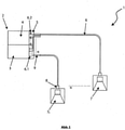
- a projector system 1 in a vehicle application in which the light and information source 2 is central and separate from the image modulators. This is shown schematically in Fig. 1 shown.
- a central light module 3 a central control system 4 are connected to the hub 5, which combines video and light signals in one cable and divides them into various output channels 9. The signal is then forwarded via the cable system 6 to each image modulator 7, connected via plug connections 8.
- the light module 3 consists of at least one light source, at least one optical system and at least one beam splitting unit.
- the light source can for example white light, RGB laser or LED.
- the optical system combines RGB color emitters by using a prism system to generate white light. Escaping light reaches the beam splitter, which splits white light.
- the light beam can be divided into several parts. The individual beam is generated by a central light module 3 with a fiber optic connection 6.1 in the hub 5.
- the central control system 4 In contrast, the central control system 4 generates the information (any image, video, text information) and transmits this signal to the hub 5 through at least one connection 6.2.
- the central control system 4 also controls the power supply, which feeds the central light module 3 and image modulators 7 .
- This is the main information center, which can receive information, for example, via Bluetooth, WiFi and USB or from the vehicle's on-board computer and transmits it via at least one connection 6.2.
- the connection to the vehicle's on-board computer enables the projection of vehicle information, such as range, anywhere inside or outside the vehicle.
- a possible cascade connection between the central projector system 2 and the vehicle's on-board computer consists, for example, in depicting traffic or emergency signs on the projection surface outside the vehicle. For example, this can be done on the Road between the front and rear of the vehicle done by image modulators 7, which are mounted on the front and rear bumper.
- FIG. 2 Figure 12 illustrates a cross-sectional view of the cable system 6, which includes fiber optic 6.1, video signal and power supply cables 6.2.
- Each image modulator 7 has an input channel 8 which is connected to the cable system 6 .
- the central projector system 2 can support multiple image modulators 7, with each image modulator 7 receiving individual video signals of different resolutions such as XGA (1024 x 768), WXGA (1280 x 800), HD (1920 x 1080) or 4K (4096 x 2160). and can project.
- An image modulator 7 consists of a system consisting of an LCD (Liquid-crystal display) or three LCDs, DLP (Digital Light Processing) or LCoS (Liquid Crystal on Silicon) systems, with optics and projection lenses being combined.
- the system 2 can be installed anywhere in the vehicle, e.g. B. under the hood or in the trunk.
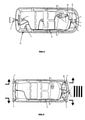
- Fig. 3 shows the central light module 4 and the information source 3 together with the cascadable projection image modulators 7 at different locations in the vehicle (interior/exterior).
- the central projector system 2 is mounted under the hood of the vehicle and with the cascadable Image modulator system 7 connected by a cable system 6.
- This concept also takes into account the possibility of integrating additional image modulators 7 by using a plug-in port with connections 8 and 9.
- Fig. 4 illustrates this plugin option of an additional portable projector.
- This option can be used, for example, for projections outside the vehicle, for example in mobile homes, in order to connect separate image modulators 7 .
- Fig. 5 12 shows an example of a system 2 in a vehicle application, where the cable system 6 is connected to imagers 7 located on the windshield, headliner, rear bumper, rear window and the window located above the tank 10.
- the image modulators 7 on the windshield can be installed at two positions, for example. Both work like an instrument panel. In modern vehicles, the instrument panel is actively used to display things like the speedometer, fuel gauge, and odometer.
- the image modulator 7 in the vehicle roof can, for example, display high-resolution videos on any surface in the vehicle interior.
- FIG. 6 shown in the form of the central projector system 2 with a cascadable image modulator 7, which is mounted on the front and rear bumper and shows traffic and emergency signals on the road there.
- the image modulator 7 can be used to display a wide variety of information on the side windows of the vehicle.
- a portable, compact projector is also the subject of this patent.
- Fig. 7 and Fig. 8 schematically represent image modulators on the side windows, the side mirrors and on the underside of the door.
- the central light and information source-based, cascadable projector system 1 is an information and projection network to enable high-resolution projection on different surfaces.
- a very compact image modulator 7 can be implemented anywhere in or on the vehicle with a separate information source 3 and light source 4 .
- the modern projector has a high resolution, which is based, for example, on laser or LED light sources. Lasers and LEDs generate a lot of heat and therefore need to be cooled.
- a patent claim is that the system 2 can be connected to the image modulator 7 via the cable system 6 . This spatial separation avoids both thermal problems and space or installation space restrictions.
- the cascadable projector system 1 can be synchronized with the video camera system and the video signal can be projected onto the back of the truck.
- a schematic representation of this patent claim is in Fig. 9 shown, in the image modulator 7, the video signal from the camera system 11 to the vehicle rear of the truck projected.
- the camera system 11 shows the traffic situation in front of the truck and informs the following traffic about it.
- the central light and information source-based cascadable projector system described above is a technology for any type of vehicle such as cars, buses, trams, trolleybuses, suburban trains, trains, transport vehicles, trucks, motorcycles, tractors, articulated lorries, airplanes, helicopters, ships, motor boats and comparable vehicles.
Landscapes
- Engineering & Computer Science (AREA)
- Physics & Mathematics (AREA)
- Mechanical Engineering (AREA)
- General Physics & Mathematics (AREA)
- Chemical & Material Sciences (AREA)
- Combustion & Propulsion (AREA)
- Transportation (AREA)
- Optics & Photonics (AREA)
- Multimedia (AREA)
- Signal Processing (AREA)
- Instrument Panels (AREA)
- Projection Apparatus (AREA)
Abstract
Das kaskadierbare Projektorensystem für Fahrzeuganwendungen basiert auf einem Konzept, bei dem zentrale Licht- und Informationsquellen vorliegen, wobei mittels eines Kabelsystems eine Verbindung zu Bildmodulatoren hergestellt wird. Bei diesem Patent handelt es sich um eine Entwicklung für vielfältige Anwendungen. Diese beinhaltet mindestens einen Bildmodulator sowie Licht- und Informationsquellen. Der Modulator besteht aus mindestens einem LCD (Liquid-Crystal Display) oder drei LCD bzw. DLP (Digital Light Processing) bzw. LCoS (Liquid Crystal on Silicon System) Systemen, wobei Optik und Projektionslinsen kombiniert werden. Eine Lichtquelle und ein Informationsmodul übertragen Licht- und Videosignale über ein Kabelsystem zum Bildmodul. Das Kabelsystem besteht aus Glasfaser-, Video,- und Spannungsversorgungskabeln in Kombination mit Hochleistungslichtquellenmodulen. Dies garantiert eine hochauflösende Videoprojektion.
Description
- Diese Erfindung bezieht sich auf ein Fahrzeug-Projektoren-System, welches über eine zentrale Licht- und Informationsquelle verfügt und mittels einem Kabelsystem mit Bildmodulatoren verbunden ist. Bei dem Lichtmodul handelt es sich zum Beispiel um einen Hochleistungslaser oder eine LED mit einer glasfasergekoppelten Quelle. Es überträgt Licht über ein Glasfaserkabel zum kaskadierbaren Bildmodulator. Auf diese Weise kann eine hochauflösende Videoprojektion auf verschiedenen Oberflächen im Fahrzeuginterieur oder -exterieur realisiert werden.
- Jüngste Entwicklungen in der Automobilindustrie zeigen auf, dass viele Unternehmen versuchen, Projektoren, Glasprojektionssysteme oder aktive Logoprojektoren in Fahrzeuge zu integrieren. Gleichzeitig schreitet die Technologie im Bereich der Projektorenentwicklung weiter voran. RGB-(Red, Green, Blue)Laser und LED (Light Emitted Diode) basierte Projektoren werden als Lichtquellen verwendet. Das Hauptziel dieses Patents besteht darin, ein zentrales, kaskadierbares Projektorensystem in einem Fahrzeug zu integrieren, wobei der Projektor-Bild-Modulator Projektionsdaten und licht von einer zentralen Quelle empfängt. Projektionsmodulatoren können an beliebigen Stellen im Fahrzeug installiert werden, wie etwa in Türen, der Heckscheibe, der Windschutzscheibe oder am Dach. Auch können diese am Fahrzeugexterieur angebracht werden, etwa an linken und rechten Fahrzeugseite, rechts und links an den Seitenspiegeln oder an der Front- bzw. Heckstoßstange.
- Die dargestellte Erfindung beinhaltet ein Konzept, bei dem das Projektorensystem zwei separate Teile aufweist: einen kaskadierbaren Projektor-Bild-Modulator sowie ein Licht- und Informationsmodul. Projektor-Bild-Modulatoren können an beliebiger Stelle im Interieur/Exterieur eines Fahrzeugs installiert werden. Beispielsweise kann die Projektion auf der Windschutzscheibe als Instrumententafel genutzt werden. Eine Frontvideokamera kann die Daten zu dem Projektor in der Heckscheibe übertragen, um Informationen von der Kamera darzustellen.
- Das Modulator-System kann im Fahrzeugexterieur installiert werden, etwa auf der Front- oder Heckstoßstange, um Verkehrs- oder Notsignale anzuzeigen. Die Informations- und Lichtquelle ist ein zentrales Modul, welches separat von den kaskadierbaren Projektor-Bild-Modulatoren zu betrachten ist. Das Modul besteht aus LED- oder Laserlichtquellen, einem Strahlenteilungssystem und einem Computer. Der Computer dient dazu, Videosignale zu den Projektoren zu übertragen, die Eingangsleistung und Datenquellen zu kontrollieren sowie mit dem Bordcomputer des Fahrzeuges zu kommunizieren. Die Verbindung zwischen einem zentralen Modul und Projektor-Bild-Modulatoren wird durch ein Kabelsystem realisiert, welches aus Glasfaser-, Video-, Audio-, und Spannungsversorgungskabeln besteht.
-
-
Abb. 1 ist eine schematische Darstellung einer zentralen Licht- und Informationsquelle, verbunden mit dem kaskadierbaren Projektorsystem. -
Abb. 2 ist eine Querschnittsdarstellung eines Verbindungskabels als Kombination von Glasfaser-, Video- und Spannungsversorgungskabel. -
Abb. 3 ist eine schematische Darstellung eines Fahrzeuges mit einer zentralen Licht- und Informationsquelle, zusammen mit einem kaskadierbaren Projektorsystem, welches an unterschiedlichen Stellen im Fahrzeug untergebracht ist. -
Abb. 4 ist eine Draufsichtdarstellung mit einer zentralen Licht- und Informationsquelle, kombiniert mit einem kaskadierbaren Projektorsystem, welches an unterschiedlichen Stellen im Fahrzeug untergebracht ist. Außerdem ist ein Plugin-Projektor-Modul auf der Rückseite dargestellt. -
Abb. 5 ist eine schematische Draufsichtdarstellung eines Fahrzeuges, welches mit einer zentralen Licht- und Informationsquelle ausgestattet ist, kombiniert mit einem kaskadierbaren Projektorsystem, welches an unterschiedlichen Stellen im Fahrzeug untergebracht ist. -
Abb. 6 ist eine schematische Draufsichtdarstellung eines Fahrzeuges, welches mit einer zentralen Licht- und Informationsquelle ausgestattet ist, zusammen mit einem kaskadierbaren Projektorsystem, welches auf der Front- und Heckstoßstange installiert ist und Verkehrs- sowie Notsignale anzeigt. -
Abb. 7 ist eine schematische Darstellung einer zentralen Licht- und Informationsquelle, verbunden mit einem kaskadierbaren Projektorsystem, positioniert auf der Türe an unterschiedlichen Positionen. -
Abb. 8 ist eine schematische Darstellung einer zentralen Licht- und Informationsquelle, verbunden mit einem kaskadierbaren Projektorsystem, positioniert auf der Scheibe und auf einem Seitenspiegel. -
Abb. 9 ist eine schematische Darstellung eines Fahrzeuges mit zentraler Licht- und Informationsquelle, kombiniert mit einem Kamerasystem zur Informationsdarstellung von Nutzerdaten auf der Fahrzeugrückseite oder den Seitenwänden eines LKWs. - Während den letzten Jahren ist die technologische und industrielle Entwicklung stark fortgeschritten. Die Gesellschaft versucht mittels Technologie überall, ob zu Hause oder in Fahrzeugen, das Leben komfortabel, sicher und zugänglich zu gestalten. Projektionssysteme finden in der Automobilindustrie eine breite Anwendung, insbesondere als Logoprojektion oder als Instrumententafelsystem. Fortschritte in den Bereichen Halbleitertechnologie und Nanotechnologie haben große Veränderungen bei Licht- und Displaysystemen ermöglicht. Unter anderem, die Projektorengröße zu reduzieren und gleichzeitig die Auflösungsqualität zu erhöhen.
- -Gegenstand dieses Patents ist ein Projektorensystem 1 in einer Fahrzeuganwendung, in der die Licht- und Informationsquelle 2 zentral und separiert von den Bildmodulatoren ist. Dies wird schematisch in
Abb. 1 dargestellt. Es handelt sich hierbei um ein Konzept, bei dem sich ein zentrales Lichtmodul 3, ein zentrales Kontrollsystem 4 mit dem Hub 5 verbinden, welches Video- und Lichtsignale in einem Kabel kombiniert und diese in verschiedene Ausgangskanäle 9 teilt. Danach wird das Signal über das Kabelsystem 6 in jeden Bildmodulator 7 weitergeleitet, verbunden über Steckverbindungen 8. - Das Lichtmodul 3 besteht aus mindestens einer Lichtquelle, mindestens einem optischen System und mindestens einer Strahlenteilungseinheit. Die Lichtquelle kann beispielsweise Weißlicht, RGB-Laser oder LED sein. Das optische System kombiniert beispielsweise RGB-Farb-Strahler, indem es ein Prismen-System nutzt, um weißes Licht zu erzeugen. Austretendes Licht gelangt zum Strahlenteiler, dieser teilt weißes Licht auf. Abhängig von den Spezifikationen und den Anforderungen an den Projektor kann der Lichtstrahl in mehrere Anteile unterteilt werden. Der individuelle Beam wird durch ein zentrales Lichtmodul 3 mit Glasfaseranschluss 6.1 im Hub 5 erzeugt.
- Demgegenüber generiert das zentrale Kontrollsystem 4 die Information (jedwede Bild-, Video-, Textinformation) und überträgt dieses Signal durch mindestens eine Verbindung 6.2 in den Hub 5. Das zentrale Kontrollsystem 4 kontrolliert zudem die Spannungsversorgung, welche das zentrale Lichtmodul 3 und Bildmodulatoren 7 speist. Es handelt sich hierbei um das Hauptinformationszentrum, welches Informationen beispielsweise via Bluetooth, WiFi und USB oder vom Bordcomputer des Fahrzeuges erhalten kann und diese über mindestens eine Verbindung 6.2 überträgt. Die Verbindung zum Bordcomputer des Fahrzeugs ermöglicht die Projektion von Fahrzeuginformationen wie beispielsweise der Reichweite an beliebigen Stellen innerhalb oder außerhalb des Fahrzeugs.
- Während dem Tankvorgang 10 wird beispielsweise oberhalb der Scheibe über den Tankinhalt informiert. Eine mögliche Kaskadenschaltung zwischen dem zentralen Projektoren-System 2 und dem Bordcomputer des Fahrzeugs besteht beispielsweise darin, Verkehrs- oder Notfallschilder auf der Projektionsoberfläche außerhalb des Fahrzeugs abzubilden. Beispielsweise kann dies auf der Straße zwischen Front und Heck des Fahrzeuges durch Bild-Modulatoren 7 erfolgen, welche auf Front- und Heckstoßstange montiert werden.
- Im Hub 5 werden Video-, Glasfaser- und Spannungsversorgungskabel in 9 zusammengeführt und mit dem Bildmodulator 7 über ein Kabelsystem 6 verbunden.
Abb. 2 stellt eine Querschnittsdarstellung des Kabelsystems 6 dar, welches Glasfaser- 6.1, Videosignal- und Spannungsversorgungskabel 6.2 umfasst. Jeder Bildmodulator 7 hat einen Eingangskanal 8, welcher mit dem Kabelsystem 6 verbunden wird. - Das zentrale Projektoren-System 2 kann mehrere Bildmodulatoren 7 unterstützen, wobei jeder Bildmodulator 7 individuelle Videosignale unterschiedlicher Auflösungen wie beispielsweise XGA (1024 x 768), WXGA (1280 x 800), HD (1920 x 1080) oder 4K (4096 x 2160) empfangen und projizieren kann. Ein Bildmodulator 7 besteht aus einem System aus einem LCD (Liquid-crystal display) oder drei LCDs, DLP (Digital Light Processing) oder LCoS (Liquid Crystal on Silicon) Systemen, wobei Optiken und Projektionslinsen kombiniert werden. Das System 2 kann an beliebiger Stelle im Fahrzeug angebracht werden, z. B. unter der Motorhaube oder im Kofferraum.
-
Abb. 3 zeigt das zentrale Lichtmodul 4 und die Informationsquelle 3 zusammen mit den kaskadierbaren Projektions-Bildmodulatoren 7 an unterschiedlichen Stellen im Fahrzeug (Interieur/Exterieur). In dieser Darstellung ist das zentrale Projektorensystem 2 unter der Motorhaube des Fahrzeuges angebracht und mit dem kaskadierbaren Bildmodulator-System 7 durch ein Kabelsystem 6 verbunden. Dieses Konzept berücksichtigt auch die Möglichkeit, zusätzliche Bildmodulatoren 7 zu integrieren, indem ein Plugin-Port mit Verbindungen 8 und 9 genutzt wird. -
Abb. 4 veranschaulicht diese Plugin-Option eines zusätzlichen portablen Projektors. Diese Option kann beispielsweise für Projektionen außerhalb des Fahrzeugs beispielsweise bei Wohnmobilen genutzt werden, um separate Bildmodulatoren 7 zu verbinden. -
Abb. 5 zeigt ein Beispiel eines Systems 2 in einer Fahrzeug-Anwendung, wobei das Kabelsystem 6 mit Bildmodulatoren 7 verbunden ist, welche sich auf der Windschutzscheibe, dem Fahrzeughimmel, der Heckstoßstange, der Heckscheibe und der oberhalb des Tanks 10 gelegenen Scheibe befinden. Die Bildmodulatoren 7 auf der Windschutzscheibe können beispielsweise an zwei Positionen installiert werden. Beide arbeiten wie eine Instrumententafel. In modernen Fahrzeugen wird die Instrumententafel aktiv genutzt, um etwa das Tachometer, die Tankanzeige und den Kilometerzähler abzubilden. Der Bildmodulator 7 am Fahrzeughimmel kann beispielsweise hochauflösende Videos auf beliebigen Oberflächen im Fahrzeuginterieur darstellen. - Ein Patentanspruch wird in
Abb. 6 in Form des zentralen Projektorensystems 2 mit einem kaskadierbaren Bildmodulator 7 dargestellt, welcher auf der Front- und Heckstoßstange angebracht ist und dort Verkehrs- und Notfallsignale auf der Straße darstellt. - Der Bildmodulator 7 kann genutzt werden, um verschiedenste Informationen auf den Seitenscheiben des Fahrzeuges darzustellen. Weiterhin ist ein tragbarer, kompakter Projektor Gegenstand dieses Patents.
-
Abb. 7 und Abb. 8 stellen schematisch Bildmodulatoren auf den Seitenscheiben, den Seitenspiegeln sowie an der Türunterseite dar. Das zentrale licht- und informationsquellenbasierte, kaskadierbare Projektorensystem 1 ist ein Informations- und Projektionsnetzwerk, um eine hochauflösende Projektion auf verschiedenen Oberflächen zu ermöglichen. Ein sehr kompakter Bildmodulator 7 kann an beliebigen Stellen in oder am Fahrzeug mit separater Informationsquelle 3 und Lichtquelle 4 implementiert werden. Der moderne Projektor besitzt eine hohe Auflösung, welche beispielsweise auf Laser- oder LED-Lichtquellen basiert. Laser und LED erzeugen viel Hitze und müssen daher gekühlt werden. - Ein Patentanspruch besteht darin, dass das System 2 mit dem Bildmodulator 7 über das Kabelsystem 6 verbunden werden kann. Diese räumliche Trennung vermeidet sowohl thermische Probleme und Platz- bzw. Bauraumrestriktionen.
- Auf Straßen und Autobahnen ist die Sicht für den nachfolgenden Verkehr häufig durch vorausfahrende LKWs eingeschränkt. In diesem Fall kann das kaskadierbare Projektorensystem 1 mit dem Video-Kamerasystem synchronisiert werden und das Videosignal kann auf die Rückseite des LKW projiziert werden. Eine schematische Darstellung dieses Patentanspruchs ist in
Abb. 9 dargestellt, in der Bildmodulator 7 das Videosignal vom Kamerasystem 11 auf die Fahrzeugrückseite des LKWs projiziert. Das Kamerasystem 11 zeigt die Verkehrssituation vor dem LKW und informiert den nachfolgenden Verkehr darüber. - Eine weitere Applikation wäre beispielsweise die Projektion von Werbung auf den Seitenwänden eines LKWs. Das oben beschriebene zentrale licht- und informationsquellenbasierte kaskadierbare Projektorensystem ist eine Technologie für beliebige Fahrzeugtypen wie beispielsweise PKW, Bus, Tram, Trolleybus, S-Bahn, Zug, Transportfahrzeuge, LKW, Motorräder, Traktoren, Sattelschlepper, Flugzeuge, Helikopter, Schiffe, Motorbote und vergleichbare Fahrzeuge.
Claims (11)
- Anordnung eines optischen Projektionssystems zur Anwendung an und/oder in Fahrzeugen, insbesondere Kraftfahrzeugen, bestehend aus wenigstens einem Lichtmodul (3) sowie einem Projektionsmodul, die von einem Kontrollsystem (4) angesteuert und von einer Energiequelle versorgt werden, wobei das Lichtmodul (3) und das Kontrollsystem (4) als zentrale Einheit ausgebildet und über ein Kabelsystem (6) angesteuert und verbunden sind.
- Anordnung nach Anspruch 1, dadurch gekennzeichnet, dass das Lichtmodul (3) eine Lichtquelle aufweist, die wahlweise mit einem Lichtstrahlsplitter bzw. -teiler, Ausgangskanälen zum Anschluß für Glasfaserkabel sowie Kühlungselementen versehen sein kann.
- Anordnung nach Anspruch 1 oder 2, dadurch gekennzeichnet, dass das Kontrollsystem (4) eine Recheneinheit in Form eines Computers, eines Mikroprozessors oder dergleichen beinhaltet, die Informationen empfängt, generiert und speichert und daraus gebildete Daten zu dem Lichtmodul (3) bzw. Projektionsmodul überträgt, wobei die Recheneinheit eine Informationseingangsschnittstelle zur Kommunikation mittels WiFi, Bluetooth, einer App oder dergleichen aufweist.
- Anordnung nach Anspruch 1, dadurch gekennzeichnet, dass das Lichtmodul (3) sowie das Projektionsmodul als kaskadierbares System ausgebildet sind, wobei das Projektionsmodul einen Bildmodulator (7) und/oder eine Bilderzeugungseinheit, sowie kombinierte Optiken und Projektionslinsen umfaßt.
- Anordnung nach einem der vorangehenden Ansprüche, dadurch gekennzeichnet, dass das/die Projektionsmodul(e) sowohl im Inneren wie auch im Äußeren eines Fahrzeuges installiert und dazu beispielsweise in den Fahrzeugtüren, links oder rechts an den Außenspiegeln oder der Heckscheibe angeordnet sein können.
- Anordnung nach einem der vorangehenden Ansprüche, dadurch gekennzeichnet, dass die Energiequelle eine Eingangsspannung im Bereich 9-54 V aufweist und eine Ausgangsleistung von 100 W generiert.
- Anordnung nach einem der vorangehenden Ansprüche, dadurch gekennzeichnet, dass das Kabelsystem (6) Glasfaser-, Video- und Spannungsversorgungskabel in einem Kabel umfasst und zudem eine Verbindungsmöglichkeit (Plug-in-Option) zu dem Projektionsmodul, auch portabel, bereitstellt.
- Anordnung nach einem der vorangehenden Ansprüche, dadurch gekennzeichnet, dass das Licht von einem direkt weißes Licht emittierenden Modul oder einem Modul mit rot/grün/blau- (RGB) Farbkombination generiert wird, wobei es sich bei der Lichtquelle beispielsweise um LED- oder Lasermodule handelt.
- Anordnung nach einem der vorangehenden Ansprüche, dadurch gekennzeichnet, dass der Bildmodulator (7) oder die Bilderzeugungseinheit aus einem LCD, drei LCDs, DLP oder LCoS Systemen besteht.
- Fahrzeug mit mindestens einem zentralen kaskadierbaren Licht- und Projektorensystem entsprechend den Ansprüchen 1 bis 9.
- Applikation von mindestens einem zentralen kaskadierbaren Licht- und Projektorensystem entsprechend einem der Ansprüche 1 bis 9 in einem Fahrzeug.
Applications Claiming Priority (1)
| Application Number | Priority Date | Filing Date | Title |
|---|---|---|---|
| DE102020005517.6A DE102020005517A1 (de) | 2020-09-09 | 2020-09-09 | Anordnung eines optischen Projektionssystems zur Anwendung an und/oder in Fahrzeugen |
Publications (1)
| Publication Number | Publication Date |
|---|---|
| EP3968631A1 true EP3968631A1 (de) | 2022-03-16 |
Family
ID=80215845
Family Applications (1)
| Application Number | Title | Priority Date | Filing Date |
|---|---|---|---|
| EP21000256.4A Withdrawn EP3968631A1 (de) | 2020-09-09 | 2021-09-08 | Anordnung eines optischen projektionssystems zur anwendung an und/ oder in fahrzeugen |
Country Status (2)
| Country | Link |
|---|---|
| EP (1) | EP3968631A1 (de) |
| DE (1) | DE102020005517A1 (de) |
Families Citing this family (2)
| Publication number | Priority date | Publication date | Assignee | Title |
|---|---|---|---|---|
| DE102021005528B3 (de) * | 2021-11-09 | 2023-03-23 | Mercedes-Benz Group AG | Kraftfahrzeug |
| DE102024123828A1 (de) * | 2024-08-21 | 2026-02-26 | Bayerische Motoren Werke Aktiengesellschaft | Beleuchtungsvorrichtung für ein kraftfahrzeug |
Citations (2)
| Publication number | Priority date | Publication date | Assignee | Title |
|---|---|---|---|---|
| US20100309391A1 (en) * | 2009-06-03 | 2010-12-09 | Honeywood Technologies, Llc | Multi-source projection-type display |
| US20180147985A1 (en) * | 2015-06-02 | 2018-05-31 | Corning Incorporated | Vehicle projection system |
-
2020
- 2020-09-09 DE DE102020005517.6A patent/DE102020005517A1/de not_active Withdrawn
-
2021
- 2021-09-08 EP EP21000256.4A patent/EP3968631A1/de not_active Withdrawn
Patent Citations (2)
| Publication number | Priority date | Publication date | Assignee | Title |
|---|---|---|---|---|
| US20100309391A1 (en) * | 2009-06-03 | 2010-12-09 | Honeywood Technologies, Llc | Multi-source projection-type display |
| US20180147985A1 (en) * | 2015-06-02 | 2018-05-31 | Corning Incorporated | Vehicle projection system |
Also Published As
| Publication number | Publication date |
|---|---|
| DE102020005517A1 (de) | 2022-03-10 |
Similar Documents
| Publication | Publication Date | Title |
|---|---|---|
| DE112015006563B4 (de) | Projektionsanzeigevorrichtung und Projektionsanzeigeverfahren | |
| EP2207700B1 (de) | Kraftfahrzeug mit einer anzeige und einer kamera | |
| WO2019149686A1 (de) | Optische einheit zur informationsdarstellung und beleuchtung im und am kraftfahrzeug | |
| EP3128356B1 (de) | Verfahren zur anzeige von informationen durch die windschutzscheibe eines kraftfahrzeuges und vorrichtung zur durchführung des verfahrens | |
| DE102013207797B4 (de) | Schminkspiegelanordnung für einen fahrzeugrücksitz | |
| EP3968631A1 (de) | Anordnung eines optischen projektionssystems zur anwendung an und/ oder in fahrzeugen | |
| DE112015002814T5 (de) | Anzeigevorrichtung für virtuelle Bilder | |
| DE102017002229A1 (de) | Anzeigevorrichtung und Verfahren zur Projektion von Anzeigeinformation in einem Fahrzeug | |
| DE102018100483A1 (de) | Automotives lichtbasiertes kommunikationssystem für benutzergeräte | |
| CN104670074A (zh) | 用于提供后组合灯功能的曲面显示装置 | |
| US20230271554A1 (en) | Head up side view mirror | |
| WO2016124713A2 (de) | Verfahren und vorrichtungen zur dateneinspiegelung | |
| US11249222B2 (en) | Optical film and manufacturing method thereof and display device | |
| CN101311037B (zh) | 机动车全景前后观察镜及视频系统 | |
| DE102008054443A1 (de) | Anzeigevorrichtung für ein Kfz sowie Verfahren für die Darstellung eines Bildes | |
| DE102023127372A1 (de) | Hybrid-Projektorsystem für ein Head-up-Display innerhalb eines Fahrzeugs | |
| DE102018200099A1 (de) | Verfahren zur Darstellung von Informationen an einer Außenseite eines Fahrzeugs | |
| DE102018121719A1 (de) | Signalanlage für Fahrzeugverband | |
| US20090122139A1 (en) | Display System for a Motor Vehicle | |
| CN109036314B (zh) | 一种液晶显示模组及其控制方法和液晶显示装置 | |
| DE102023127370A1 (de) | Hybrid-Projektorsystem mit Selbsttest | |
| DE202013101078U1 (de) | Head-up-Anzeigegerät für ein Smartphone | |
| DE102019115311A1 (de) | Anzeigevorrichtung, Anzeigesystem, Fahrzeug mit einer Anzeigevorrichtung und/oder einem Anzeigesystem sowie Verfahren zum Betrieb | |
| DE102011121558B4 (de) | Anzeigevorrichtung und Verfahren zum Betrieb einer Anzeigevorrichtung | |
| DE102018202319A1 (de) | Verfahren und Vorrichtung zum Betreiben eines Kamera-Monitor-Systems für ein Kraftfahrzeug |
Legal Events
| Date | Code | Title | Description |
|---|---|---|---|
| PUAI | Public reference made under article 153(3) epc to a published international application that has entered the european phase |
Free format text: ORIGINAL CODE: 0009012 |
|
| STAA | Information on the status of an ep patent application or granted ep patent |
Free format text: STATUS: THE APPLICATION HAS BEEN PUBLISHED |
|
| AK | Designated contracting states |
Kind code of ref document: A1 Designated state(s): AL AT BE BG CH CY CZ DE DK EE ES FI FR GB GR HR HU IE IS IT LI LT LU LV MC MK MT NL NO PL PT RO RS SE SI SK SM TR |
|
| STAA | Information on the status of an ep patent application or granted ep patent |
Free format text: STATUS: THE APPLICATION IS DEEMED TO BE WITHDRAWN |
|
| 18D | Application deemed to be withdrawn |
Effective date: 20220917 |