EP3968484A1 - Control for electrical converters - Google Patents
Control for electrical converters Download PDFInfo
- Publication number
- EP3968484A1 EP3968484A1 EP20195279.3A EP20195279A EP3968484A1 EP 3968484 A1 EP3968484 A1 EP 3968484A1 EP 20195279 A EP20195279 A EP 20195279A EP 3968484 A1 EP3968484 A1 EP 3968484A1
- Authority
- EP
- European Patent Office
- Prior art keywords
- converter
- voltage
- grid
- conv
- power
- Prior art date
- Legal status (The legal status is an assumption and is not a legal conclusion. Google has not performed a legal analysis and makes no representation as to the accuracy of the status listed.)
- Pending
Links
Images




Classifications
-
- H—ELECTRICITY
- H02—GENERATION; CONVERSION OR DISTRIBUTION OF ELECTRIC POWER
- H02J—ELECTRIC POWER NETWORKS; CIRCUIT ARRANGEMENTS OR SYSTEMS FOR SUPPLYING OR DISTRIBUTING ELECTRIC POWER; SYSTEMS FOR STORING ELECTRIC ENERGY
- H02J3/00—Circuit arrangements for AC mains or AC distribution networks
- H02J3/38—Arrangements for feeding a single network from two or more generators or sources in parallel; Arrangements for feeding already energised networks from additional generators or sources in parallel
- H02J3/381—Dispersed generators
-
- H—ELECTRICITY
- H02—GENERATION; CONVERSION OR DISTRIBUTION OF ELECTRIC POWER
- H02J—ELECTRIC POWER NETWORKS; CIRCUIT ARRANGEMENTS OR SYSTEMS FOR SUPPLYING OR DISTRIBUTING ELECTRIC POWER; SYSTEMS FOR STORING ELECTRIC ENERGY
- H02J3/00—Circuit arrangements for AC mains or AC distribution networks
- H02J3/38—Arrangements for feeding a single network from two or more generators or sources in parallel; Arrangements for feeding already energised networks from additional generators or sources in parallel
- H02J3/46—Controlling the sharing of generated power between the generators, sources or networks
- H02J3/48—Controlling the sharing of active power
-
- H—ELECTRICITY
- H02—GENERATION; CONVERSION OR DISTRIBUTION OF ELECTRIC POWER
- H02J—ELECTRIC POWER NETWORKS; CIRCUIT ARRANGEMENTS OR SYSTEMS FOR SUPPLYING OR DISTRIBUTING ELECTRIC POWER; SYSTEMS FOR STORING ELECTRIC ENERGY
- H02J2101/00—Supply or distribution of decentralised, dispersed or local electric power generation
- H02J2101/40—Hybrid power plants, i.e. a plurality of different generation technologies being operated at one power plant
Definitions
- the present disclosure relates to the control of electrical converters, in particular to a method for controlling an electrical converter for use in an AC power grid and an apparatus for controlling an electrical converter for use in an AC power grid.
- control loops have the following purposes:
- Figure 2 shows a typical implementation of such a direct droop control method with additional control loops. As can be seen from these additional measures, the control method becomes more and more complex and in general is difficult to tune. Negative interactions between droop control loops, virtual impedance, voltage control loop and current control loop are common, especially in applications with low converter switching frequency.
- the mathematical equations of a synchronous generator are implemented in a controller to emulate the behavior of the generator.
- the mathematical machine equations are solved for the stator voltage which is given as a reference either directly to the modulation stage or to subsequent cascaded voltage and current control loops.
- the mathematical machine equations are solved for the stator currents which are given as references to subsequent current control loops.
- control loops have the following purposes:
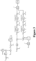
- FIG. 3 A basic VSM control implementation is shown in Fig. 3 . Furthermore, additional measures can be used to improve the performance of the virtual generator:
- the present disclosure relates to a simple and systematic grid supporting controller and a method for simple and systematic grid support.
- the present disclosure relates to a method for controlling an electrical converter for use in an AC power grid.
- the method comprises calculating a rotation angle ⁇ of a voltage waveform of an AC output voltage of the converter based on an active power P conv of the converter, a reference active power P conv ref of the converter and a frequency deviation ⁇ 2 of the voltage of the AC power grid from a nominal grid frequency of the AC power grid.
- the method further comprises controlling the electrical converter to output an AC output voltage having the calculated rotation angle ⁇ .
- the method is computer-implemented.
- the rotation angle ⁇ is calculated based on a weighted sum of the active power P conv of the converter, the reference active power P conv ref of the converter and the frequency deviation ⁇ 2 of the voltage of the AC power grid.
- the rotation angle ⁇ is calculated based on the integral of the weighted sum of the active power P conv of the converter, the reference active power P conv ref of the converter and the frequency deviation ⁇ 2 of the voltage of the AC power grid.
- the weighting factors of the weighted sum are determined by a linear-quadratic regulator, LQR, feedback vector calculated based on a linear dynamic model of the frequency deviation ⁇ 2 of the voltage of the AC power grid, and the active power P conv of the converter.
- the linear dynamic model is based on a swing equation.
- the swing equation includes a term with a droop constant representing the droop characteristics of the grid voltage frequency ⁇ g .
- the swing equation includes a term representing a low pass filter, the low pass filter representing a delayed response of the grid voltage frequency ⁇ g .
- the grid voltage frequency deviation ⁇ 2 is estimated based on a voltage frequency of the converter, the derivative of the active power P conv of the converter, and a low-pass filter.
- the reference active power P conv ref of the converter is estimated based on a nominal grid frequency ⁇ n , a voltage of the point of common coupling v pcc , a virtual inductance L virt between a voltage of the converter v conv and the voltage of the point of common coupling v pcc .
- the present disclosure also relates to a computer-readable medium comprising instructions which, when executed by a computer, cause the computer to carry out the method of any of the aforementioned embodiments.
- the present disclosure also relates to an apparatus for controlling an electrical converter for use in an AC power grid.
- the apparatus comprises a processor which is configured to calculate a rotation angle ⁇ of a voltage waveform of an AC output voltage of the converter based on an active power P conv of the converter, a reference active power P conv ref of the converter and a frequency deviation ⁇ 2 of the voltage of the AC power grid from a nominal grid frequency of the AC power grid.
- the processor is also configured to control the electrical converter to output an AC output voltage having the calculated rotation angle ( ⁇ ).
- the processor is configured to calculate the rotation angle ⁇ based on a weighted sum of the active power P conv of the converter, the reference active power P conv ref of the converter and the frequency deviation ⁇ 2 of the voltage of the AC power grid, in particular based on the integral of the weighted sum of the active power P conv of the converter, the reference active power P conv ref of the converter and the frequency deviation ⁇ 2 of the voltage of the AC power grid.
- the processor is configured to determine the weighting factors of the weighted sum by a linear-quadratic regulator, LQR, feedback vector calculated based on a linear dynamic model of the frequency deviation ⁇ 2 of the voltage of the AC power grid, and the active power P conv of the converter.
- LQR linear-quadratic regulator
- the linear dynamic model is based on a swing equation.
- the swing equation includes a term with a droop constant representing the droop characteristics of the grid voltage frequency ⁇ g .
- the swing equation includes a term representing a low pass filter, the low pass filter representing a delayed response of the grid voltage frequency ⁇ g .
- the processor is configured to estimate the grid voltage frequency deviation ⁇ 2 based on a voltage frequency of the converter, the derivative of the active power P conv of the converter, and a low-pass filter.
- the processor is configured to estimate the reference active power P conv ref of the converter based on a nominal grid frequency ⁇ n , a voltage of the point of common coupling v pcc , a virtual inductance L virt between a voltage of the converter v conv and the voltage of the point of common coupling v pcc .
- a converter to a power grid is considered.
- the output voltage of the converter is considered as the control input and is denoted with v.
- v we thus neglect the dynamics of the converter filter.
- the grid is modeled as a synchronous machine (SM) behind a grid impedance.
- the SM is assumed to have mechanical power input Pg.
- Pg mechanical power input
- the converter has the following parameters:
- the SM is assumed to be controlled with droop control and a governor which introduces a delay in the response.
- the set point P g ref may also be low-pass filtered.
- the model of the grid is based on the swing equation and is represented in the above described ⁇ -frame.
- the acceleration/deceleration of the grid frequency stops, and the grid voltage is periodic with frequency ⁇ n .
- ⁇ ⁇ 0 1 0 0 ⁇ D J in ⁇ k g ⁇ n J in 0 ⁇ lp ⁇ ⁇ lp ⁇ A ⁇ ⁇ + 0 1 ⁇ n J in 0 ⁇ B ⁇ P conv ⁇ P g ref .
- i g ss I sin ⁇ n t + ⁇ i ⁇ cos ⁇ n t + ⁇ i .
- x ⁇ 0 1 0 0 0 ⁇ D J in ⁇ k g ⁇ n J in 1 ⁇ n J in 0 ⁇ lp ⁇ ⁇ lp 0 0 ⁇ 3 2 VV g ⁇ n L g cos ⁇ ss 0 0 ⁇ A x + 0 1 ⁇ n J in 0 0 ⁇ F ⁇ P g ref + 0 0 0 0 3 2 VV g ⁇ n L g cos ⁇ ss ⁇ B ⁇ ⁇ .
- control input ⁇ is the converter voltage frequency.
- this dynamic system can be used for a feedback control where ⁇ is controlled with linear state feedback.
- variable ⁇ 3 can be neglected as it would require knowledge about the low-pass filter cut-off frequency ⁇ 1p and it is not reasonable to assume this knowledge.
- the feedback gains are designed using the LQR feedback model.
- the Q matrix generally imposes penalties on the deviations of the states from their reference values.
- the R matrix which in this case is a scalar, is used to penalize the controller actuator.
- the tuning of the LQR controller is thus dependent on the two weights q 44 and R.
- the steady state relation between the steady state power and frequency is a function of the relationship between the gains k 1 and k 2 .
- said relaxing condition improves the dynamic performance.
- the power reference can be calculated via virtual inductance.
- the steady state power of the system depends on the load which is connected to the network.
- the steady state power would be set as (a fraction of) the reference power P conv ref for the power in the linear feedback control.
- the load is generally unknown, this is not (always) possible to do directly.
- this approach would be highly complex, parameter dependent and non-robust.
- to compute the reference for the converter power is to consider a virtual inductance L virt between the converter voltage v and the PCC voltage v pcc .
- the converter voltage and the PCC voltage can be measured, and the corresponding steady state current through the virtual inductance is calculated. This current is then multiplied with the converter voltage to produce a virtual power which is used as a reference for the linear feedback control of the converter.
- the feedback control makes use of the grid frequency deviation ⁇ 2 and the converter power P conv .
- the converter power is directly measurable, but the grid frequency must be estimated.
- an estimator for the grid frequency is derived, which estimates the frequency based on measurements of the converter power.
- the only measurement required by the control system is the converter power.
- the derivative of the converter power satisfies P ⁇ conv ⁇ 3 2 VV g ⁇ n L g cos ⁇ ss ⁇ K ⁇ ⁇ ⁇ 3 2 VV g ⁇ n L g cos ⁇ ss ⁇ 2 .
- ⁇ est is the cut off frequency of a low pass filter.
- the low pass filter may be required to remove the high frequency noise in the derivative of the converter output power.
- Figure 5 shows a schematic illustration of the aforementioned equation.
- FIG. 6 shows a schematic illustration of an apparatus 10 for controlling an electrical converter for use in an AC power grid according to an embodiment of the present disclosure.
- the apparatus includes a processor 100, such as, e.g. a microprocessor or an Application Specific Integrated Circuit (ASIC) and a storage unit 110.
- the storage unit 110 may be any data storage device that stores a program code 112, which is accessed and executed by the processor 100.
- the processor 100 may implement any one of the steps in exemplified embodiments above of the apparatus 10, e.g., by executing the program code 112.
- the processor is configured to calculate a rotation angle ⁇ (of a voltage waveform) of an AC output voltage of the converter based on an active power P conv of the converter, a reference active power P conv ref of the converter and a frequency deviation ⁇ 2 of the voltage of the AC power grid from a nominal grid frequency of the AC power grid; and control the electrical converter to output an AC output voltage having the calculated rotation angle ( ⁇ ).
Landscapes
- Engineering & Computer Science (AREA)
- Power Engineering (AREA)
- Inverter Devices (AREA)
Abstract
Description
- The present disclosure relates to the control of electrical converters, in particular to a method for controlling an electrical converter for use in an AC power grid and an apparatus for controlling an electrical converter for use in an AC power grid.
- Traditionally, electric power is generated by synchronous machines (SM), distributed to consumers via a power grid and used by passive consumers. However, the increased use of renewable energy has caused an increase in converter-interfaced energy resources. In renewable energy generation systems, the electric power is often DC, as in e.g., photovoltaic (PV) plants, or variable frequency AC, as in e.g., wind power plants. In such systems, grid connected DC/AC converters are required to feed power to the AC distribution grid. Thus, the increased presence of renewable energy implies that synchronous generators are more and more replaced by grid tied DC/AC converters.
- It has been shown in many studies that there is a risk of grid instability if the utility grid is equipped with a high amount of renewable energy resources that do not employ any grid supporting control strategy. The reason for the instability is that such resources do not adapt their power injection to the grid according to the actual power demand in the grid. Such grid-agnostic current/power control strategies have been common in most converter-interfaced applications for a long time. However, in the last decades, more stringent regulations have been put in place, e.g. for PV converters. Today, PV converters have to gradually reduce the injected active power if the grid frequency increases above nominal. This behavior is a first step into the direction of grid-supporting power converter control. The injected active power is slowly adapted in response to the actual needs of the grid. Such a simple method only provides steady-state grid support, i.e. it still relies on synchronous generators in the grid that take over transient load changes.
- In the meantime, more sophisticated converter control methods have been developed for insular grids, microgrids and railway grids. These control methods aim to provide not only steady-state grid support but also transient grid support. Converter-interfaced energy resources with such control methods are able to fully replace conventional synchronous generators in the grid. It is possible to run a grid without any conventional synchronous generator connected to it - a situation that has become common e.g. in railway grids already. There are a number of unique characteristics of such control methods that provide full grid support, i.e. both transient and steady-state grid support. One of the key requirements is the ability to automatically adapt the amount of injected power to the grid according to the demand of the various loads. This is achieved, inter alia, by changing the behavior from grid-agnostic constant power injection to a behavior that is closer to a voltage source. The converters equipped with such control methods adapt and share the injected power automatically such that they provide the actual power demanded from the various loads in the grid. Because of reasons of backwards compatibility with legacy equipment in AC power generation and distribution, the control methods aim to provide "inertia" to the grid, meaning that the rate of change of the grid frequency is limited. The combined effect of voltage source characteristics and inertia leads to a characteristic that is very close to the behavior of a synchronous generator. Such control methods provide full grid support and can fully replace synchronous generators in the grid.
- Existing grid supporting control mechanisms can be classified into two main groups
- Droop control approaches: The control law is based on the steady-state coupling of frequency (or angle) and power flow in inductive grids. Various implementation variants exist and several ways of improving the method have been proposed over the last years. In most implementation variants, the method creates a voltage reference which has to be tracked with additional cascaded voltage- and current control loops.
- Virtual generator approaches: The control law is based on the principle of emulating the behavior of a synchronous generator. The mathematical model describing the behavior of the generator is implemented in the controller directly. Various implementation variants exist that differ mainly in the level of detail and the complexity of the implemented equations.
- The basic concept of droop control for inductive grids in exemplarily shown in
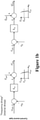
Figures 1a and1b . In the direct method (Fig. 1a ), the converter output voltage frequency and amplitude are adapted as a function of the output active power and reactive power. In other words, the output frequency/amplitude of the converter is changed depending on the measured active/reactive power. In the indirect method (Fig. 1b ), the relationship is inverted, and the output active and reactive power are changed in response to the measured PCC (point of common coupling) voltage frequency and amplitude. In other words, the output active/reactive power of the converter is changed depending on the measured voltage frequency/amplitude. In this case, the output power reference can be tracked with subsequent inner control loops, e.g. current controllers. - Both droop control methods (direct and inverse) are usually not used in its basic form. Various additional control loops have to be implemented to make the concept applicable. The control loops have the following purposes:
- Cascaded voltage and current control loops: track the voltage and frequency reference given by the direct method and provide current control including current limitation.
- Current control loop and PLL (phase lock loop): track the active/reactive power references given by the inverse droop method and provide current control including current limitation. Provide grid synchronization and grid frequency measurement.
- Virtual impedance loop: emulate a virtual output impedance in order to improve the performance of droop control under various aspects.
- Additional measures can be performed to improve the performance of droop control:
- Low-pass filtering of the measured active and reactive power can provide a virtual inertia effect.
- Low-pass filtering the virtual impedance reference is often required to reduce amplification of high frequency noise caused by the derivative used for the calculation of a virtual inductance.
- An additional PLL for the direct method is often required for synchronization with the grid before closing the MCB of the converter or during fault cases.
- Feedforward gains for the grid current and the PCC voltage improve the performance of the PI control loops.
- A lead-lag filter can be used to provide damping of low-frequency oscillations.
-
Figure 2 shows a typical implementation of such a direct droop control method with additional control loops. As can be seen from these additional measures, the control method becomes more and more complex and in general is difficult to tune. Negative interactions between droop control loops, virtual impedance, voltage control loop and current control loop are common, especially in applications with low converter switching frequency. - The main drawbacks of droop control are the following:
- Difficult tuning approach, high commissioning effort.
- Interactions between control loops due to insufficient bandwidth separation in converters with low switching frequency.
- Too many parameters to tune (typically around 15 parameters) with unknown interactions.
- Insufficient damping of low frequency oscillations.
- Insufficient reference tracking performance in strong grids.
- In the virtual generator approach, the mathematical equations of a synchronous generator are implemented in a controller to emulate the behavior of the generator. In the direct approach, also known as the voltage source type, the mathematical machine equations are solved for the stator voltage which is given as a reference either directly to the modulation stage or to subsequent cascaded voltage and current control loops. In the inverse approach of the virtual generator approach, i.e. the so-called current source type, the mathematical machine equations are solved for the stator currents which are given as references to subsequent current control loops.
- The various implementation variants of the virtual generator approach mainly differ in the complexity (order) of the adopted machine equations. Both, the direct and the inverse virtual generator approach, usually require various additional control loops to be implemented to make the concept applicable. The control loops have the following purposes:
- Cascaded voltage and current control loops: track the voltage and frequency reference given by the direct method and provide current control including current limitation.
- Current control loop and PLL: track the active/reactive power references given by the inverse method and provide current control including current limitation. Provide grid synchronization and grid frequency measurement.
- Virtual impedance loop: emulate a virtual stator impedance if it is not included in the high order machine model already.
- A basic VSM control implementation is shown in
Fig. 3 . Furthermore, additional measures can be used to improve the performance of the virtual generator: - An additional PLL for the direct method can be used for synchronization with the grid before closing the MCB of the converter or during fault cases.
- AVR (automatic voltage regulation) control can be used to improve the voltage regulation at the PCC.
- Feedforward gains for the grid current and the PCC voltage can be used to improve the performance of the PI control loops.
- Damper winding emulation can be used to improve damping of low-frequency oscillations.
- In a simple inverse method, the virtual inertia effect can be emulated with a derivative of the measured grid frequency.
- Low-pass filtering the virtual impedance reference can be to reduce amplification of high frequency noise caused by the derivative used for the calculation of a virtual inductance.
- As can be seen above, the control method becomes more and more complex and in general is difficult to tune. Negative interactions between virtual generator control loops, AVR, virtual impedance, voltage control loop and current control loop are common, especially in applications with low converter switching frequency. The main drawbacks of virtual generator control are:
- Difficult tuning approach, high commissioning effort.
- Interactions between control loops due to insufficient bandwidth separation in converters with low switching frequency.
- Too many parameters to tune (typically around 15 parameters) with unknown interactions.
- Insufficient reference tracking performance in strong grids.
- Loose of synchronism during faults.
- The present disclosure relates to a simple and systematic grid supporting controller and a method for simple and systematic grid support.
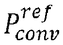
- The present disclosure relates to a method for controlling an electrical converter for use in an AC power grid. The method comprises calculating a rotation angle θ of a voltage waveform of an AC output voltage of the converter based on an active power Pconv of the converter, a reference active power
- Various embodiments may preferably implement the following feature:
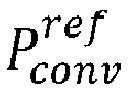
Preferably, the method is computer-implemented. - Preferably, the rotation angle θ is calculated based on a weighted sum of the active power Pconv of the converter, the reference active power

- Preferably, the weighting factors of the weighted sum are determined by a linear-quadratic regulator, LQR, feedback vector calculated based on a linear dynamic model of the frequency deviation ξ 2 of the voltage of the AC power grid, and the active power Pconv of the converter.
- Preferably, the linear dynamic model is based on a swing equation.
- Preferably, the swing equation includes a term with a droop constant representing the droop characteristics of the grid voltage frequency ωg .
- Preferably, the swing equation includes a term representing a low pass filter, the low pass filter representing a delayed response of the grid voltage frequency ωg .
- Preferably, the grid voltage frequency deviation ξ 2 is estimated based on a voltage frequency of the converter, the derivative of the active power Pconv of the converter, and a low-pass filter.
- Preferably, the reference active power

- The present disclosure also relates to a computer-readable medium comprising instructions which, when executed by a computer, cause the computer to carry out the method of any of the aforementioned embodiments.
- The present disclosure also relates to an apparatus for controlling an electrical converter for use in an AC power grid. The apparatus comprises a processor which is configured to calculate a rotation angle θ of a voltage waveform of an AC output voltage of the converter based on an active power Pconv of the converter, a reference active power

- Various embodiments may preferably implement the following feature:
- Preferably, the processor is configured to calculate the rotation angle θ based on a weighted sum of the active power Pconv of the converter, the reference active power


- Preferably, the processor is configured to determine the weighting factors of the weighted sum by a linear-quadratic regulator, LQR, feedback vector calculated based on a linear dynamic model of the frequency deviation ξ 2 of the voltage of the AC power grid, and the active power Pconv of the converter.
- Preferably, the linear dynamic model is based on a swing equation.
- Preferably, the swing equation includes a term with a droop constant representing the droop characteristics of the grid voltage frequency ωg .
- Preferably, the swing equation includes a term representing a low pass filter, the low pass filter representing a delayed response of the grid voltage frequency ωg .
- Preferably, the processor is configured to estimate the grid voltage frequency deviation ξ 2 based on a voltage frequency of the converter, the derivative of the active power Pconv of the converter, and a low-pass filter.
- Preferably, the processor is configured to estimate the reference active power

- For the method according to the present disclosure, the following modeling conditions have been assumed:
- The converter dynamics are neglected, and the converter output voltage is directly controlled. For current limitation and fault handling, the method according to the present disclosure can be combined with subsequent low-level control algorithms (e.g. cascaded voltage-current control, or virtual impedance emulation and current control).
- The grid frequency is modeled by a swing equation.
- The grid voltage amplitude is assumed to be constant.
- The above and other aspects and their implementations are described in greater detail in the drawings, the descriptions, and the claims.
-
Figures 1a and1b show basic concepts of droop control for inductive grids. -
Figure 2 shows a typical implementation of a direct droop control method with additional control loops. -
Figure 3 shows an illustration of a basic virtual synchronous motor implementation. -
Figure 4a shows an illustration of the concept of calculating the rotation angle θ of an AC output voltage of a converter according to an embodiment of the present disclosure. -
Figure 4b shows a schematic illustration of the rotational angle θ of the voltage waveform of the AC output voltage of the converter -
Figure 5 shows an illustration of the concept of determination of a frequency deviation ξ 2 of the voltage of the AC power grid from a nominal grid frequency of the AC power grid according to an embodiment of the present disclosure. -
Figure 6 shows a schematic illustration of anapparatus 10 for controlling an electrical converter for use in an AC power grid according to an embodiment of the present disclosure. - In the derivation of the control algorithm for the control method according to the present disclosure, it is assumed that the grid and converter voltages and currents are balanced three-phase in the form:

- Using an amplitude invariant αβ-transformation, the voltage can be denoted as:

- It is understood by the skilled person that the representation of the current can be transformed in the same manner.
- According to an exemplary embodiment, a converter to a power grid is considered. The output voltage of the converter is considered as the control input and is denoted with v. We thus neglect the dynamics of the converter filter. The grid is modeled as a synchronous machine (SM) behind a grid impedance. The SM is assumed to have mechanical power input Pg. Thus, the SM has the following parameters:
- Lg: grid inductance
- ig: grid current
- Pg: grid power
- The converter has the following parameters:
- v: converter voltage
- Pconv : converter power
- The SM is assumed to be controlled with droop control and a governor which introduces a delay in the response. The power Pg is controlled as

-

- kg : droop gain
- ωn : nominal grid frequency
- ωg : grid frequency
- ωlp : cutoff frequency of the low-pass filter used to model the governor delay
- s: is the Laplace operator
- The set point

- The model of the grid is based on the swing equation and is represented in the above described αβ-frame. The grid voltage amplitude can be considered to be constant, but the frequency to be varying so that the voltage vg of the grid can be written as:

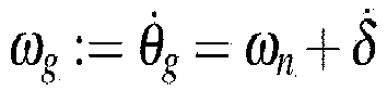
- The rotation angle θg can be modeled as


- δ̇: 1st order time derivative of variable δ
- δ̈: 2nd order time derivative of variable δ
- Jin : inertia
- D: damping
- The power provided by the grid converter is

- When the reference power is achieved, the acceleration/deceleration of the grid frequency stops, and the grid voltage is periodic with frequency ωn . In the grid model, the often unknown value of the damping can be set to zero. It is known in the art (see, e.g. [1]) that the droop controller of the SM makes use of the frequency

- The dynamics of the variable δ can be written in the state
space form 


- With ξ 2 = δ̇ being the deviation from the nominal grid frequency.
- The dynamics of ξ are

- The grid current dynamics are

- In the derivation of a dynamic equation for the active power, the dynamics of the grid current is neglected, and it is assumed that the grid current instantaneously reaches its steady state value. In other words, it is assumed that the grid current is assumed to be at its steady state, which is determined by the converter and grid voltage.
- The steady state solution


- Putting this expression of


- Using the above steady state expression for


- The time derivative of this expression is


- The grid state above and the active power can now be described in a common system description which can be used for a linear feedback design which will be described below.
- Let

- The dynamics of x are:

- It is understood by the skilled person that the control input θ̇ is the converter voltage frequency. In the following, this dynamic system can be used for a feedback control where θ̇ is controlled with linear state feedback.
- The feedback model according to an embodiment of the present disclosure is a linear-quadratic regulator (LQR) which for which the following feedback structure is assumed:

- Without loss of generality, the variable ξ3 can be neglected as it would require knowledge about the low-pass filter cut-off frequency ω1p and it is not reasonable to assume this knowledge.
- The feedback gains are designed using the LQR feedback model. Considering the aforementioned dynamics of x, the cost matrices can be chosen as:


- The right choice of the cost matrix Q assures that the gains klqr,1 and klqr,3 are very small and can be neglected.
- For the droop curve tracking, one can use the fact that at steady state, the frequency of the converter and grid must coincide, which means that the steady state control input must satisfy:

- θ̇ss : converter voltage frequency in the steady state
-

-

- This implies:

- In other words, the steady state relation between the steady state power and frequency, known as the droop curve, is a function of the relationship between the gains k1 and k2. The droop constant kdroop is assumed to be given, and this imposes the following relation between the feedback gains:

- It should be noted that the gains obtained from the LQR design do not necessarily satisfy the
relation 
- Satisfying the droop curve can be ensured by adding a slow outer integral loop: To impose the droop curve at steady state, an integral term can be added which penalizes deviations from the curve:

Figure 4a. Figure 4b shows a schematic illustration of the rotational angle θ of the voltage waveform of the AC output voltage of the converter. This rotation angle θ is used for controlling the electrical converter. - According to an embodiment, the power reference can be calculated via virtual inductance. The steady state power of the system depends on the load which is connected to the network. Ideally, the steady state power would be set as (a fraction of) the reference power


- This value can be used for the power reference:

- According to the present disclosure, the feedback control makes use of the grid frequency deviation ξ2 and the converter power Pconv. The converter power is directly measurable, but the grid frequency must be estimated. Thus, according to an embodiment, an estimator for the grid frequency is derived, which estimates the frequency based on measurements of the converter power. Thus, with this estimator, the only measurement required by the control system is the converter power.
- As was shown above, the derivative of the converter power satisfies

- Solving this equation for the grid frequency ξ2 leads to

- Thus, the grid frequency deviation can be estimated as ξ̂2 of the grid frequency as

Figure 5 shows a schematic illustration of the aforementioned equation. -
Figure 6 shows a schematic illustration of anapparatus 10 for controlling an electrical converter for use in an AC power grid according to an embodiment of the present disclosure. The apparatus includes aprocessor 100, such as, e.g. a microprocessor or an Application Specific Integrated Circuit (ASIC) and astorage unit 110. Thestorage unit 110 may be any data storage device that stores aprogram code 112, which is accessed and executed by theprocessor 100. Theprocessor 100 may implement any one of the steps in exemplified embodiments above of theapparatus 10, e.g., by executing theprogram code 112. The processor is configured to calculate a rotation angle θ (of a voltage waveform) of an AC output voltage of the converter based on an active power Pconv of the converter, a reference active power
- While various embodiments of the present disclosure have been described above, it should be understood that they have been presented by way of example only, and not by way of limitation. Likewise, the various diagrams may depict an example architectural or configuration, which are provided to enable persons of ordinary skill in the art to understand exemplary features and functions of the present disclosure. Such persons would understand, however, that the present disclosure is not restricted to the illustrated example architectures or configurations, but can be implemented using a variety of alternative architectures and configurations. Additionally, as would be understood by persons of ordinary skill in the art, one or more features of one embodiment can be combined with one or more features of another embodiment described herein. Thus, the breadth and scope of the present disclosure should not be limited by any of the above-described exemplary embodiments.
Claims (15)
- A method for controlling an electrical converter for use in an AC power grid,
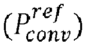
the method comprising:calculating a rotation angle (θ) of a voltage waveform of an AC output voltage of the converter based on an active power (Pconv ) of the converter, a reference active power controlling the electrical converter to output an AC output voltage having the calculated rotation angle (θ).
 - The method according to claim 1, wherein the rotation angle (θ) is calculated based on a weighted sum of the active power (Pconv ) of the converter, the reference active power

- The method according to claim 2, wherein the weighting factors of the weighted sum are determined by a linear-quadratic regulator, LQR, feedback vector calculated based on a linear dynamic model of the frequency deviation (ξ 2) of the voltage of the AC power grid, and the active power (Pconv ) of the converter.
- The method according to claim 3, wherein the linear dynamic model is based on a swing equation.
- The method according to claim 4, wherein the swing equation includes a term with a droop constant representing the droop characteristics of the grid voltage frequency (ωg ).
- The method according to claim 4 or 5, wherein the swing equation includes a term representing a low pass filter, the low pass filter representing a delayed response of the grid voltage frequency (ωg ).
- The method according to any one of claims 1 to 6, wherein the grid voltage frequency deviation (ξ 2) is estimated based on a voltage frequency of the converter, the derivative of the active power (Pconv ) of the converter, and a low-pass filter.
- The method according to any one of claims 1 to 7, wherein the reference active power

- An apparatus for controlling an electrical converter for use in an AC power grid,
the apparatus comprising a processor being configured to:calculate a rotation angle (θ) of a voltage waveform of an AC output voltage of the converter based on an active power (Pconv ) of the converter, a reference active power control the electrical converter to output an AC output voltage having the calculated rotation angle (θ).
 - The apparatus according to claim 9, wherein the processor is configured to calculate the rotation angle (θ) based on a weighted sum of the active power (Pconv ) of the converter, the reference active power


- The apparatus according to claim 10, wherein the processor is configured to determine the weighting factors of the weighted sum by a linear-quadratic regulator, LQR, feedback vector calculated based on a linear dynamic model of the frequency deviation (ξ 2) of the voltage of the AC power grid, and the active power (Pconv ) of the converter.
- The apparatus according to claim 11, wherein the linear dynamic model is based on a swing equation.
- The apparatus according to any of claims 9 to 11, wherein the processor is configured to estimate the grid voltage frequency deviation (ξ 2) based on a voltage frequency of the converter, the derivative of the active power (Pconv ) of the converter, and a low-pass filter.
- The apparatus according to any of claims 9 to 12, wherein the processor is configured to estimate the reference active power

- A computer-readable medium comprising instructions which, when executed by a computer, cause the computer to carry out the method of any of claims 1 to 8.
Priority Applications (1)
| Application Number | Priority Date | Filing Date | Title |
|---|---|---|---|
| EP20195279.3A EP3968484A1 (en) | 2020-09-09 | 2020-09-09 | Control for electrical converters |
Applications Claiming Priority (1)
| Application Number | Priority Date | Filing Date | Title |
|---|---|---|---|
| EP20195279.3A EP3968484A1 (en) | 2020-09-09 | 2020-09-09 | Control for electrical converters |
Publications (1)
| Publication Number | Publication Date |
|---|---|
| EP3968484A1 true EP3968484A1 (en) | 2022-03-16 |
Family
ID=72470158
Family Applications (1)
| Application Number | Title | Priority Date | Filing Date |
|---|---|---|---|
| EP20195279.3A Pending EP3968484A1 (en) | 2020-09-09 | 2020-09-09 | Control for electrical converters |
Country Status (1)
| Country | Link |
|---|---|
| EP (1) | EP3968484A1 (en) |
Cited By (3)
| Publication number | Priority date | Publication date | Assignee | Title |
|---|---|---|---|---|
| CN116599159A (en) * | 2023-07-13 | 2023-08-15 | 湖北长江电气有限公司 | Intelligent control method of photovoltaic grid-connected inverter |
| EP4358342A1 (en) * | 2022-10-21 | 2024-04-24 | Siemens Gamesa Renewable Energy Innovation & Technology S.L. | Operating a power converter |
| EP4607737A1 (en) * | 2024-02-23 | 2025-08-27 | Siemens Gamesa Renewable Energy A/S | Method for controlling a wind power plant, computer program product and wind power plant |
Citations (1)
| Publication number | Priority date | Publication date | Assignee | Title |
|---|---|---|---|---|
| CN105006834A (en) * | 2015-06-10 | 2015-10-28 | 合肥工业大学 | Optimal virtual inertia control method based on virtual synchronous generator |
-
2020
- 2020-09-09 EP EP20195279.3A patent/EP3968484A1/en active Pending
Patent Citations (1)
| Publication number | Priority date | Publication date | Assignee | Title |
|---|---|---|---|---|
| CN105006834A (en) * | 2015-06-10 | 2015-10-28 | 合肥工业大学 | Optimal virtual inertia control method based on virtual synchronous generator |
Non-Patent Citations (2)
| Title |
|---|
| MARKOVIC UROS ET AL: "Fast Frequency Control Scheme through Adaptive Virtual Inertia Emulation", 2018 IEEE INNOVATIVE SMART GRID TECHNOLOGIES - ASIA (ISGT ASIA), IEEE, 22 May 2018 (2018-05-22), pages 787 - 792, XP033404821, DOI: 10.1109/ISGT-ASIA.2018.8467920 * |
| YAZDANI SARA ET AL: "Power Synchronization PID Control Method for Grid-Connected Voltage-Source Converters", 2020 IEEE KANSAS POWER AND ENERGY CONFERENCE (KPEC), IEEE, 13 July 2020 (2020-07-13), pages 1 - 6, XP033812285, [retrieved on 20200814], DOI: 10.1109/KPEC47870.2020.9167628 * |
Cited By (6)
| Publication number | Priority date | Publication date | Assignee | Title |
|---|---|---|---|---|
| EP4358342A1 (en) * | 2022-10-21 | 2024-04-24 | Siemens Gamesa Renewable Energy Innovation & Technology S.L. | Operating a power converter |
| WO2024083929A1 (en) * | 2022-10-21 | 2024-04-25 | Siemens Gamesa Renewable Energy Innovation & Technology S.L. | Operating a power converter |
| CN116599159A (en) * | 2023-07-13 | 2023-08-15 | 湖北长江电气有限公司 | Intelligent control method of photovoltaic grid-connected inverter |
| CN116599159B (en) * | 2023-07-13 | 2023-10-13 | 湖北长江电气有限公司 | Intelligent control method of photovoltaic grid-connected inverter |
| EP4607737A1 (en) * | 2024-02-23 | 2025-08-27 | Siemens Gamesa Renewable Energy A/S | Method for controlling a wind power plant, computer program product and wind power plant |
| WO2025176452A1 (en) * | 2024-02-23 | 2025-08-28 | Siemens Gamesa Renewable Energy A/S | Method for controlling a wind power plant, computer program product and wind power plant |
Similar Documents
| Publication | Publication Date | Title |
|---|---|---|
| Mallemaci et al. | A comprehensive comparison of virtual synchronous generators with focus on virtual inertia and frequency regulation | |
| US11043817B2 (en) | Method for feeding electrical power into an electrical power supply network | |
| Paquette et al. | Sharing transient loads: Causes of unequal transient load sharing in islanded microgrid operation | |
| Haddadi et al. | A gain-scheduled decoupling control strategy for enhanced transient performance and stability of an islanded active distribution network | |
| Rosyadi et al. | Simplified model of variable speed wind turbine generator for dynamic simulation analysis | |
| EP3968484A1 (en) | Control for electrical converters | |
| Thommessen et al. | Virtual synchronous machine control for doubly fed induction machine-based wind energy conversion systems | |
| Lyu et al. | Unified grid-forming control of PMSG wind turbines for fast frequency response and MPPT | |
| Chang-Chien et al. | Estimation of/spl beta/for adaptive frequency bias setting in load frequency control | |
| Narula | Grid-forming wind power plants | |
| Chernet et al. | Input impedance based nyquist stability criterion for subsynchronous resonance analysis in DFIG based wind farms | |
| Palombi et al. | Impact on power system frequency dynamics from an HVDC transmission system with converter stations controlled as virtual synchronous machines | |
| Neumann et al. | Grid-forming control and operational strategies for offshore wind turbines incorporating electrical and mechanical modelling | |
| Encarnação et al. | Virtual inertia for power converter control | |
| Narula et al. | Impact of steady-state grid-frequency deviations on the performance of grid-forming converter control strategies | |
| Guo et al. | Exploration of the relationship between inertia enhancement and DC-link capacitance for grid-connected converters | |
| CN107221957B (en) | Control method for optical storage grid-connected interface system | |
| CN114204860A (en) | Three-phase inverter control method and system based on virtual synchronous power generation technology | |
| Gryning et al. | Stability boundaries for offshore wind park distributed voltage control | |
| Peng et al. | A modified vector control strategy for DFIG based wind turbines to ride-through voltage dips | |
| Minchala-Avila et al. | A model predictive control approach for integrating a master generation unit in a microgrid | |
| Konstantinopoulos et al. | Dynamic active power control in type-3 wind turbines for transient stability enhancement | |
| Marinescu | A robust coordinated control of the doubly-fed induction machine for wind turbines: a state-space based approach | |
| Tahir et al. | Improving Low Voltage Ride-Through Capabilities in Wound Field Synchronous Generator-Based Wind Power Systems using Inertial Kinetic Energy Storage | |
| Liu | Capacitor Voltage Synchronizing Control of 100% Full-Scale Wind Power Generator-Supplied Power Systems |
Legal Events
| Date | Code | Title | Description |
|---|---|---|---|
| PUAI | Public reference made under article 153(3) epc to a published international application that has entered the european phase |
Free format text: ORIGINAL CODE: 0009012 |
|
| STAA | Information on the status of an ep patent application or granted ep patent |
Free format text: STATUS: THE APPLICATION HAS BEEN PUBLISHED |
|
| AK | Designated contracting states |
Kind code of ref document: A1 Designated state(s): AL AT BE BG CH CY CZ DE DK EE ES FI FR GB GR HR HU IE IS IT LI LT LU LV MC MK MT NL NO PL PT RO RS SE SI SK SM TR |
|
| STAA | Information on the status of an ep patent application or granted ep patent |
Free format text: STATUS: REQUEST FOR EXAMINATION WAS MADE |
|
| 17P | Request for examination filed |
Effective date: 20220916 |
|
| RBV | Designated contracting states (corrected) |
Designated state(s): AL AT BE BG CH CY CZ DE DK EE ES FI FR GB GR HR HU IE IS IT LI LT LU LV MC MK MT NL NO PL PT RO RS SE SI SK SM TR |
|
| STAA | Information on the status of an ep patent application or granted ep patent |
Free format text: STATUS: EXAMINATION IS IN PROGRESS |
|
| 17Q | First examination report despatched |
Effective date: 20230913 |
|
| RAP1 | Party data changed (applicant data changed or rights of an application transferred) |
Owner name: HITACHI ENERGY LTD Owner name: ABB SCHWEIZ AG |
|
| GRAP | Despatch of communication of intention to grant a patent |
Free format text: ORIGINAL CODE: EPIDOSNIGR1 |
|
| STAA | Information on the status of an ep patent application or granted ep patent |
Free format text: STATUS: GRANT OF PATENT IS INTENDED |
|
| INTG | Intention to grant announced |
Effective date: 20260325 |