EP3968464A1 - Electronic device - Google Patents
Electronic device Download PDFInfo
- Publication number
- EP3968464A1 EP3968464A1 EP20806028.5A EP20806028A EP3968464A1 EP 3968464 A1 EP3968464 A1 EP 3968464A1 EP 20806028 A EP20806028 A EP 20806028A EP 3968464 A1 EP3968464 A1 EP 3968464A1
- Authority
- EP
- European Patent Office
- Prior art keywords
- antenna
- slot
- electronic device
- rotating shaft
- metal
- Prior art date
- Legal status (The legal status is an assumption and is not a legal conclusion. Google has not performed a legal analysis and makes no representation as to the accuracy of the status listed.)
- Granted
Links
Images



Classifications
-
- G—PHYSICS
- G06—COMPUTING OR CALCULATING; COUNTING
- G06F—ELECTRIC DIGITAL DATA PROCESSING
- G06F1/00—Details not covered by groups G06F3/00 - G06F13/00 and G06F21/00
- G06F1/16—Constructional details or arrangements
- G06F1/1613—Constructional details or arrangements for portable computers
- G06F1/1615—Constructional details or arrangements for portable computers with several enclosures having relative motions, each enclosure supporting at least one I/O or computing function
- G06F1/1616—Constructional details or arrangements for portable computers with several enclosures having relative motions, each enclosure supporting at least one I/O or computing function with folding flat displays, e.g. laptop computers or notebooks having a clamshell configuration, with body parts pivoting to an open position around an axis parallel to the plane they define in closed position
-
- G—PHYSICS
- G06—COMPUTING OR CALCULATING; COUNTING
- G06F—ELECTRIC DIGITAL DATA PROCESSING
- G06F1/00—Details not covered by groups G06F3/00 - G06F13/00 and G06F21/00
- G06F1/16—Constructional details or arrangements
- G06F1/1613—Constructional details or arrangements for portable computers
- G06F1/1633—Constructional details or arrangements of portable computers not specific to the type of enclosures covered by groups G06F1/1615 - G06F1/1626
- G06F1/1675—Miscellaneous details related to the relative movement between the different enclosures or enclosure parts
- G06F1/1681—Details related solely to hinges
-
- G—PHYSICS
- G06—COMPUTING OR CALCULATING; COUNTING
- G06F—ELECTRIC DIGITAL DATA PROCESSING
- G06F1/00—Details not covered by groups G06F3/00 - G06F13/00 and G06F21/00
- G06F1/16—Constructional details or arrangements
- G06F1/1613—Constructional details or arrangements for portable computers
- G06F1/1633—Constructional details or arrangements of portable computers not specific to the type of enclosures covered by groups G06F1/1615 - G06F1/1626
- G06F1/1684—Constructional details or arrangements related to integrated I/O peripherals not covered by groups G06F1/1635 - G06F1/1675
- G06F1/1698—Constructional details or arrangements related to integrated I/O peripherals not covered by groups G06F1/1635 - G06F1/1675 the I/O peripheral being a sending/receiving arrangement to establish a cordless communication link, e.g. radio or infrared link, integrated cellular phone
-
- H—ELECTRICITY
- H01—ELECTRIC ELEMENTS
- H01Q—ANTENNAS, i.e. RADIO AERIALS
- H01Q1/00—Details of, or arrangements associated with, antennas
- H01Q1/12—Supports; Mounting means
- H01Q1/22—Supports; Mounting means by structural association with other equipment or articles
- H01Q1/2258—Supports; Mounting means by structural association with other equipment or articles used with computer equipment
- H01Q1/2266—Supports; Mounting means by structural association with other equipment or articles used with computer equipment disposed inside the computer
-
- H—ELECTRICITY
- H01—ELECTRIC ELEMENTS
- H01Q—ANTENNAS, i.e. RADIO AERIALS
- H01Q1/00—Details of, or arrangements associated with, antennas
- H01Q1/48—Earthing means; Earth screens; Counterpoises
-
- H—ELECTRICITY
- H01—ELECTRIC ELEMENTS
- H01Q—ANTENNAS, i.e. RADIO AERIALS
- H01Q1/00—Details of, or arrangements associated with, antennas
- H01Q1/50—Structural association of antennas with earthing switches, lead-in devices or lightning protectors
-
- H—ELECTRICITY
- H01—ELECTRIC ELEMENTS
- H01Q—ANTENNAS, i.e. RADIO AERIALS
- H01Q13/00—Waveguide horns or mouths; Slot antennas; Leaky-waveguide antennas; Equivalent structures causing radiation along the transmission path of a guided wave
- H01Q13/10—Resonant slot antennas
-
- H—ELECTRICITY
- H01—ELECTRIC ELEMENTS
- H01Q—ANTENNAS, i.e. RADIO AERIALS
- H01Q21/00—Antenna arrays or systems
- H01Q21/28—Combinations of substantially independent non-interacting antenna units or systems
-
- H—ELECTRICITY
- H01—ELECTRIC ELEMENTS
- H01Q—ANTENNAS, i.e. RADIO AERIALS
- H01Q5/00—Arrangements for simultaneous operation of antennas on two or more different wavebands, e.g. dual-band or multi-band arrangements
- H01Q5/30—Arrangements for providing operation on different wavebands
- H01Q5/307—Individual or coupled radiating elements, each element being fed in an unspecified way
- H01Q5/314—Individual or coupled radiating elements, each element being fed in an unspecified way using frequency dependent circuits or components, e.g. trap circuits or capacitors
- H01Q5/328—Individual or coupled radiating elements, each element being fed in an unspecified way using frequency dependent circuits or components, e.g. trap circuits or capacitors between a radiating element and ground
Definitions
- This application relates to the field of mobile communications technologies, and in particular, to an electronic device.
- notebook computers With the rapid development of notebook computers, existing WiFi communications technologies hardly meet communication needs of notebook computers. Therefore, notebook computers use multi-band antennas such as LTE to enhance their wireless Internet access capabilities. This is a general trend and a major challenge for this product.
- FIG. 1a shows a specific manner of arranging an LTE antenna.
- An LTE antenna 2 is arranged in a window on the top of a display screen, and a clearance of an LTE antenna 1 is 13-20 mm.
- the LTE antenna 1 exists far away from an interference source.
- the LTE antenna 1 is located on the top of the display screen 1, the LTE antenna 1 inevitably occupies a specific area of the display screen, contradicting the full-screen requirement.
- the prior art further uses a form of the LTE antenna 2 shown in FIG. 1b .
- the LTE antenna 2 is arranged in a window of the housing C 3 of the notebook computer.
- isolation between the arranged LTE antenna 2 and the WiFi antenna is low, affecting performance of the LTE antenna 2. Therefore, there is an urgent need for a reasonable LTE antenna arrangement solution to improve the performance of the LTE antenna.
- This application provides an electronic device, so as to improve a clearance of an antenna and improve performance of the antenna.
- an electronic device includes a first part and a second part rotatably connected to the first part through a metal rotating shaft.
- the electronic device may be a notebook computer.
- the first part includes a display screen and a metal housing, and the display screen is arranged in the metal housing.
- the electronic device further includes at least one first antenna.
- the first antenna includes a radiating unit for radiating a signal.
- the radiating unit includes a slot arranged in the metal housing and a part of the metal rotating shaft coupled to the slot, and the slot is located on a side of the metal housing close to the metal rotating shaft.
- arranging the slot on a side of the metal housing close to the metal rotating shaft can improve positions of the first antenna and another antenna, thereby increasing a clearance between the antennas.
- arranging the metal rotating shaft and the slot to jointly serve as the radiating unit of the antenna improves performance of the antenna.
- using a slot antenna as the first antenna can help achieve a full-screen effect of the display screen.
- a minimum distance from the slot to the metal rotating shaft is within a specified threshold.
- the specified threshold should ensure that the slot and the metal rotating shaft can be coupled and electrically connected, that is, the used minimum distance between the slot and the metal rotating shaft should ensure that the slot can excite a current on the metal rotating shaft.
- the specified threshold may be 2-10 mm, for example, a different distance such as 2 mm, 4 mm, 6 mm, 8 mm, or 10 mm.
- the slot is located on the side of the metal housing close to the metal rotating shaft, and more specifically, located in a corner of the side of the metal housing close to the metal rotating shaft.
- the corner refers to a joint between two adjacent side walls of the metal housing.
- the slot is an L-shaped slot, and a horizontal portion and a vertical portion of the L-shaped slot are respectively arranged along two adjacent side walls of the metal housing. Arrangement along the two side walls forming a corner of the metal housing maximizes the use of the corner space of the metal housing.
- a length of the vertical portion is 20-70 mm
- a length of the horizontal portion is 5-40 mm.
- different solutions can be used.
- the selected length of the vertical portion is 20 mm, 40 mm, 60 mm, or 70 mm.
- the horizontal portion is arranged in different sizes such as 5 mm, 10 mm, 20 mm, 30 mm, or 40 mm.
- selected widths of the horizontal portion and the vertical portion may be between 1-4 mm.
- the widths of the horizontal portion and the vertical portion are 1 mm, 2 mm, 3 mm, 4 mm, or a different width.
- the slot may alternatively be a slot of another shape, such as a straight-shaped slot or another type of slot.
- one or two first antennas may be arranged.
- slots of the two first antennas are symmetrically arranged on two sides of the metal rotating shaft. This makes full use of the space on the metal housing to prepare the slot.
- the slot may be located on the side wall of the metal housing, or on a side of the metal housing away from the display screen. In this way, the slot may be arranged at different positions.
- the slot is further filled with an insulating layer to ensure integrity of appearance of the metal housing.
- the first antenna further includes a feeding unit, the feeding unit includes a feed point and a feeder, and a tuning switch circuit is arranged on the feeder.
- An antenna with adjustable low frequency and ultra-wideband in intermediate and high frequencies without tuning is formed.
- the tuning switch circuit includes a plurality of parallel branches, and a selection switch for connecting one of the branches and the feeder. At least one branch is provided with a capacitor or an inductor. The adjustment of different frequency bands can be implemented through the cooperation of the arranged selector switch and different branches.
- the first antenna further includes a ground wire, the ground wire is connected to the slot, and the ground wire is provided with an inductor or a capacitor.
- a short circuit of a radio frequency band is formed through grounding of the capacitor or the inductor.
- the foregoing first antenna may be a different antenna, for example, the first antenna is an LTE antenna, a GPS antenna, or a WiFi antenna.
- the electronic device further includes a second antenna or a third antenna, achieving a good communication effect.
- the electronic device is a notebook computer or another foldable electronic device.
- the notebook computer is used as an example.
- the electronic device includes a housing A, a housing D, and a housing C.
- the housing A is a housing for fixing a display screen
- the housing D and the housing C enclose space for accommodating components such as a hard disk and a processor of the electronic device.
- the antenna is arranged on the housing A.
- a notebook computer is used as an example for description.
- the electronic device provided in the embodiments of this application is not limited to a notebook computer, and may alternatively be another foldable electronic device.
- the electronic device 10 provided in the embodiments of this application includes a first part and a second part 11 rotatably connected to the first part.
- the first part includes a display screen 14 and a metal housing 17 (housing A), and the display screen 14 is fixed on the metal housing 17.
- the second part 11 includes a housing D and a housing C, and the housing D and the housing C enclose space for accommodating electronic components such as a motherboard and a hard disk of the electronic device.
- the housing D and the housing C refer to a housing D and a housing C of a notebook computer in the prior art.
- connection can be implemented through the foregoing rotatable connection between the housing A and the housing D or housing C. Still referring to FIG. 3 , when the first part and the second part 11 are rotatably connected, the rotational connection is implemented through a rotating shaft. Specifically, the housing A may be rotatably connected to the housing D or the housing C through the rotating shaft.
- the first part and the second part 11 may be rotatably connected through one rotating shaft, or may be rotatably connected through two rotating shafts.
- the rotating shaft can be made of a conductive material, for example, the rotating shaft is a metal rotating shaft 12.
- the metal rotating shaft 12 not only serves as a structure for rotationally connecting the first part and the second part 11, but also can serve as a communications structure of the electronic device.
- the electronic device 10 further includes at least one first antenna, and the first antenna may be a different antenna, such as an LTE antenna, a GPS antenna, a WiFi antenna, or another type of antenna.
- the first antenna includes a feeding unit 16 and a radiating unit connected to the feeding unit 16, and the radiating unit is used for radiating a signal.
- the radiating unit includes two parts: a slot 13 arranged in the metal housing 17 and a part of the metal rotating shaft 12 coupled to the slot 13.
- the slot 13 is located on a side of the metal housing 17 close to the metal rotating shaft 12.
- a specified minimum distance c between the slot 13 and the metal rotating shaft 12 is within a specified threshold. The specified threshold should ensure that the slot 13 and the metal rotating shaft 12 can be coupled and electrically connected.
- the slot 13 can excite a current on the metal rotating shaft 12, so that the metal rotating shaft 12 can be used as a part of the radiating unit of the first antenna.
- the slot 13 excites the metal rotating shaft 12 to generate a current, an end of the metal rotating shaft 12 closest to the slot 13 is excited to generate a current for participating in the radiation of the antenna.
- the foregoing minimum distance refers to the smallest distance from the slot 13 to the end of the metal rotating shaft 12.
- the specified threshold may be 2-10 mm.
- the minimum distance c shown in FIG. 3 may be any length between 2-10 mm, such as 2 mm, 4 mm, 6 mm, 8 mm, or 10 mm.
- a shape of the arranged slot 13 may be set as needed.
- the slot 13 is an L-shaped slot, and the L-shaped slot includes two parts: a horizontal portion 132 and a vertical portion 131, respectively.
- the horizontal portion 132 and the vertical portion 131 of the slot 13 are respectively arranged along two adjacent side walls of the metal housing 17, and a bending direction of the L-shaped slot is the same as a bending direction along a corner of the metal housing 17.
- the corner refers to a joint between the two side walls of the metal housing 17. Still referring to FIG.
- a first side wall of the metal housing 17 is rotatably connected to the second part 11 through the metal rotating shaft 12, and the horizontal portion 132 of the slot 13 is arranged along a length direction of the first side wall (a length direction parallel to the rotating shaft).
- the metal housing 17 further has a second side wall connected to the first side wall, and the vertical portion 131 of the slot 13 is arranged along a length direction of the second side wall (a length direction perpendicular to the rotating shaft). Therefore, the foregoing corner may refer to a joint between the first side wall and the second side wall.
- the slot 13 is located on an outer side of the end of the metal rotating shaft 12.
- the foregoing outer side refers to: when the first part and the second part 11 are rotatably connected through one rotating shaft, an area along a length direction of the rotating shaft and outside the metal rotating shaft 12; when the first part and the second part 11 are rotatably connected through two metal rotating shafts 12, the foregoing outer side refers to a side away from the opposite ends of the two metal rotating shafts 12. For details, refer to the position for arranging the slot 13 shown in FIG. 3 .
- the slot 13 may be arranged at different positions of the metal housing 17.
- the metal housing 17 includes a bottom housing and a side wall connected to the bottom housing.
- the bottom housing of the metal housing 17 faces away from a display surface of the display screen 14, and the side wall of the metal housing 17 covers a side wall of the display screen 14.
- the slot 13 may be arranged on the side wall of the metal housing 17.
- the slot 13 may alternatively be arranged in the bottom housing of the metal housing 17.
- the slot 13 is filled with an insulating layer, such as an insulating layer of silica gel or plastic, to ensure integrity of the entire metal housing 17 in terms of appearance.
- an insulating layer such as an insulating layer of silica gel or plastic
- the horizontal portion 132 and the vertical portion 131 of the slot 13 may be arranged based on an actual situation.
- a size of the vertical portion 131 may be set to be relatively large.
- a size is set to be relatively small.
- specific sizes of the vertical portion 131 and the horizontal portion 132 to be arranged can be selected based on an operating frequency band of the first antenna. For example, in the slot 13 shown in FIG. 4 , the length L of the vertical portion 131 is 20-70 mm.
- the length L of the vertical portion 131 may be any length between 20-70 mm, such as 20 mm, 40 mm, 60 mm, or 70 mm.
- the length W of the horizontal portion 132 is between 5-40 mm.
- the length W of the horizontal portion 132 may be any length between 5-40 mm, such as 5 mm, 10 mm, 20 mm, 30 mm, or 40 mm.
- selected widths d of the horizontal portion 132 and the vertical portion 131 may be between 1-4 mm.
- the widths d of the horizontal portion 132 and the vertical portion 131 may be any width between 1-4 mm, such as 1 mm, 2 mm, 3 mm, or 4 mm. Therefore, during specific arrangement of the slot 13, the slot 13 may be a slot formed based on the values of L, W, and d listed above.
- the foregoing L-shaped slot 13 is only an example, and the slot 13 of the first antenna provided in the embodiments of this application may alternatively be a straight-shaped slot, and the length direction of the slot 13 is a length direction along the first side wall.
- a slot 13 of another shape may alternatively be used.
- no matter which form of the slot 13 is used it should be ensured that the minimum distance between the slot 13 and the metal rotating shaft 12 is within the foregoing specified threshold, so as to ensure the electrical connection between the slot 13 and the metal rotating shaft 12.
- a parasitic stub may further be used, and the parasitic stub is coupled to the radiating unit.
- the arrangement of the parasitic stub can improve a radiation effect of the radiating unit.
- the first antenna further includes a feeding unit 16.
- the feeding unit 16 includes a feed point and a feeder connected to the feed point. When in use, the feed point couples a signal to the radiating unit through the feeder.
- the feed point is arranged on a circuit board of the electronic device 10 and connected to a radio frequency circuit on the circuit board.
- a connection position between the feeder and the radiating unit is located on a side of the radiating unit close to the metal rotating shaft 12.
- the feeder of the feeding unit 16 is connected to the horizontal portion 132 of the slot 13.
- a tuning switch circuit may further be arranged on the arranged feeder to form an antenna with adjustable low frequency and ultra-wideband in intermediate and high frequencies without tuning.
- the tuning switch circuit includes a plurality of parallel branches, and a selection switch for connecting one of the branches and the feeder. At least one branch is provided with a capacitor or an inductor.
- the adjustment of different frequency bands can be implemented through the cooperation of the arranged selector switch and different branches.
- one of the branches of the parallel circuit is provided with a capacitor, and another branch is provided with an inductor, or an inductor and a capacitor are arranged and connected in series to form a circuit.
- capacitors with different capacitance values may be respectively arranged on multiple branches, or inductors with different inductance values may be respectively arranged on multiple branches.
- a selector switch is used to select different branches for connection with the radiating unit.
- the first antenna further includes a ground wire 15, and the ground wire 15 is connected to the other side of the radiating unit. As shown in FIG. 3 and FIG. 4 , when the radiating unit uses an L-shaped slot, the ground wire 15 is connected to the vertical portion 131 of the radiating unit.
- an inductor or a capacitor is further arranged on the arranged ground wire 15, and a short circuit of a radio frequency band is formed through grounding of the capacitor or the inductor arranged on the ground wire 15.
- FIG. 3 shows two first antennas and the two first antennas are symmetrically arranged on the metal housing 17. More specifically, the two first antennas are arranged at two opposite corners of the metal housing 17. As shown in FIG. 3 , the radiating unit of each first antenna uses an L-shaped slot 13, and the slots 13 of the two first antennas are symmetrically arranged on two sides of the metal rotating shaft 12. For a specific arrangement manner, refer to the foregoing description of the slot 13. This can make full use of the space on the metal housing 17 to prepare the slot 13.
- the first antenna is arranged at the corner of the metal housing 17, and the slot 13 and a part of the metal rotating shaft 12 are used as the radiating unit.
- the space of the metal housing 17 is fully used and the arranged slot 13 does not affect the full-screen development of the display screen 14 and the thinning development of the electronic device 10.
- the performance of the antenna and the full screen and thin profile of the electronic device 10 are well combined.
- the first antenna shown in FIG. 3 was simulated, and the results are shown in FIG. 5 and FIG. 6 .
- a return loss of the first antenna provided in the embodiments of this application is less than -5 dB, and the performance of the first antenna is relatively good.
- the impedance of the first antenna provided in the embodiments of this application is relatively close to the center of the circle. The closer the impedance is to the center of the circle, the closer the impedance is to 50 ohms, and the better the performance of the antenna is.
- the antenna is arranged on the side of the display surface of the display screen 14 in FIG. 1a , inevitably affecting the display area of the display screen 14.
- the slot 13 arranged in the metal housing 17 and the part of the metal rotating shaft 12 are used as the radiating unit. This does not affect the display surface of the display screen 14, and therefore further facilitates the full-screen development.
- the antenna is arranged on the housing C of the notebook computer, but for the notebook computer, the housing C is provided with many electronic components and antennas.
- the first antenna is arranged on the metal housing 17 away from the antenna arranged in the housing C, thereby improving the isolation between the antennas.
- the electronic device 10 provided in the embodiments of this application may further include a second antenna or a third antenna.
- the second antenna or the third antenna may be a WiFi antenna or another antenna.
- the arrangement positions of the second antenna and the third antenna refer to the known antenna arrangement positions on the notebook computer.
- the first antenna because the first antenna is arranged on the metal housing 17, there is a good clearance between the first antenna and another antenna.
Landscapes
- Engineering & Computer Science (AREA)
- Computer Hardware Design (AREA)
- Theoretical Computer Science (AREA)
- General Engineering & Computer Science (AREA)
- Physics & Mathematics (AREA)
- Human Computer Interaction (AREA)
- General Physics & Mathematics (AREA)
- Mathematical Physics (AREA)
- Support Of Aerials (AREA)
Abstract
Description
- This application claims priority to
Chinese Patent Application No. 201910397778.3, filed with the China National Intellectual Property Administration on May 14, 2019 - This application relates to the field of mobile communications technologies, and in particular, to an electronic device.
- With the rapid development of notebook computers, existing WiFi communications technologies hardly meet communication needs of notebook computers. Therefore, notebook computers use multi-band antennas such as LTE to enhance their wireless Internet access capabilities. This is a general trend and a major challenge for this product.
- However, the notebook computer restricts the LTE multi-band antenna due to the characteristics of the product. The body of the existing notebook computer usually uses a fully metalized housing A, housing C, and housing D, limiting the design of the antenna. Therefore, when an antenna is arranged in the prior art, as shown in
FIG. 1a. FIG. 1a shows a specific manner of arranging an LTE antenna. AnLTE antenna 2 is arranged in a window on the top of a display screen, and a clearance of anLTE antenna 1 is 13-20 mm. When theLTE antenna 1 is arranged in the manner shown inFIG. 1a , theLTE antenna 1 exists far away from an interference source. However, because theLTE antenna 1 is located on the top of thedisplay screen 1, theLTE antenna 1 inevitably occupies a specific area of the display screen, contradicting the full-screen requirement. The prior art further uses a form of theLTE antenna 2 shown inFIG. 1b . InFIG. 1b , theLTE antenna 2 is arranged in a window of thehousing C 3 of the notebook computer. However, when this manner is used, isolation between the arrangedLTE antenna 2 and the WiFi antenna is low, affecting performance of theLTE antenna 2. Therefore, there is an urgent need for a reasonable LTE antenna arrangement solution to improve the performance of the LTE antenna. - This application provides an electronic device, so as to improve a clearance of an antenna and improve performance of the antenna.
- According to a first aspect, an electronic device is provided. The electronic device includes a first part and a second part rotatably connected to the first part through a metal rotating shaft. The electronic device may be a notebook computer. During specific arrangement, the first part includes a display screen and a metal housing, and the display screen is arranged in the metal housing. In addition, the electronic device further includes at least one first antenna. During specific arrangement, the first antenna includes a radiating unit for radiating a signal. The radiating unit includes a slot arranged in the metal housing and a part of the metal rotating shaft coupled to the slot, and the slot is located on a side of the metal housing close to the metal rotating shaft. In the foregoing technical solution, arranging the slot on a side of the metal housing close to the metal rotating shaft can improve positions of the first antenna and another antenna, thereby increasing a clearance between the antennas. In addition, arranging the metal rotating shaft and the slot to jointly serve as the radiating unit of the antenna improves performance of the antenna. Moreover, using a slot antenna as the first antenna can help achieve a full-screen effect of the display screen.
- During specific arrangement of the radiating unit, a minimum distance from the slot to the metal rotating shaft is within a specified threshold. The specified threshold should ensure that the slot and the metal rotating shaft can be coupled and electrically connected, that is, the used minimum distance between the slot and the metal rotating shaft should ensure that the slot can excite a current on the metal rotating shaft.
- During specific setting of the foregoing specified threshold, the specified threshold may be 2-10 mm, for example, a different distance such as 2 mm, 4 mm, 6 mm, 8 mm, or 10 mm.
- During specific arrangement of the slot, the slot is located on the side of the metal housing close to the metal rotating shaft, and more specifically, located in a corner of the side of the metal housing close to the metal rotating shaft. The corner refers to a joint between two adjacent side walls of the metal housing.
- During specific arrangement of the slot, the slot is an L-shaped slot, and a horizontal portion and a vertical portion of the L-shaped slot are respectively arranged along two adjacent side walls of the metal housing. Arrangement along the two side walls forming a corner of the metal housing maximizes the use of the corner space of the metal housing.
- During specific arrangement of the vertical portion and the horizontal portion, different sizes may be selected according to needs. For example, a length of the vertical portion is 20-70 mm, and a length of the horizontal portion is 5-40 mm. During specific arrangement, different solutions can be used. For example, the selected length of the vertical portion is 20 mm, 40 mm, 60 mm, or 70 mm. The horizontal portion is arranged in different sizes such as 5 mm, 10 mm, 20 mm, 30 mm, or 40 mm. In addition, selected widths of the horizontal portion and the vertical portion may be between 1-4 mm. For example, the widths of the horizontal portion and the vertical portion are 1 mm, 2 mm, 3 mm, 4 mm, or a different width.
- Certainly, in addition to the foregoing L-shaped slot, the slot may alternatively be a slot of another shape, such as a straight-shaped slot or another type of slot.
- During specific arrangement of the first antenna, one or two first antennas may be arranged. For example, there are two first antennas, and slots of the two first antennas are symmetrically arranged on the metal housing. This improves a communication effect of the electronic device.
- During specific arrangement of two first antennas, slots of the two first antennas are symmetrically arranged on two sides of the metal rotating shaft. This makes full use of the space on the metal housing to prepare the slot.
- In addition, during arrangement of the slot, the slot may be located on the side wall of the metal housing, or on a side of the metal housing away from the display screen. In this way, the slot may be arranged at different positions.
- During arrangement of the slot, the slot is further filled with an insulating layer to ensure integrity of appearance of the metal housing.
- During specific arrangement of the first antenna, the first antenna further includes a feeding unit, the feeding unit includes a feed point and a feeder, and a tuning switch circuit is arranged on the feeder. An antenna with adjustable low frequency and ultra-wideband in intermediate and high frequencies without tuning is formed.
- During specific arrangement of the foregoing tuning switch circuit, the tuning switch circuit includes a plurality of parallel branches, and a selection switch for connecting one of the branches and the feeder. At least one branch is provided with a capacitor or an inductor. The adjustment of different frequency bands can be implemented through the cooperation of the arranged selector switch and different branches.
- During specific arrangement of the first antenna, the first antenna further includes a ground wire, the ground wire is connected to the slot, and the ground wire is provided with an inductor or a capacitor. A short circuit of a radio frequency band is formed through grounding of the capacitor or the inductor.
- The foregoing first antenna may be a different antenna, for example, the first antenna is an LTE antenna, a GPS antenna, or a WiFi antenna.
- In addition to the foregoing first antenna, the electronic device further includes a second antenna or a third antenna, achieving a good communication effect.
-
-
FIG. 1a is a schematic structural diagram of a notebook computer in the prior art; -
FIG. 1b is a schematic structural diagram of another notebook computer in the prior art; -
FIG. 2 is a schematic structural diagram of an electronic device according to an embodiment of this application; -
FIG. 3 is a schematic structural diagram of an electronic device according to an embodiment of this application; -
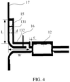
FIG. 4 is a specific schematic structural diagram of a first antenna according to an embodiment of this application; -
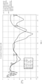
FIG. 5 is a diagram of a return loss of an antenna according to an embodiment of this application; and -
FIG. 6 is a Smith impedance chart of an antenna according to an embodiment of this application. - To make the objectives, technical solutions, and advantages of this application clearer, the following further describes this application in detail with reference to the accompanying drawings. A specific operation method in a method embodiment may also be applied to an apparatus embodiment or a system embodiment. In the descriptions of this application, unless otherwise specified, "a plurality of" means two or more.
- An electronic device provided in the embodiments of this application is first described. The electronic device is a notebook computer or another foldable electronic device. The notebook computer is used as an example. The electronic device includes a housing A, a housing D, and a housing C. The housing A is a housing for fixing a display screen, and the housing D and the housing C enclose space for accommodating components such as a hard disk and a processor of the electronic device. During arrangement of an antenna, the antenna is arranged on the housing A. However, as electronic devices are developing towards a full screen, it is necessary to provide a new electronic device. The following describes the electronic device provided in the embodiments of this application with reference to accompanying drawings and embodiments.
- To facilitate understanding of the electronic device provided in the embodiments of this application, a notebook computer is used as an example for description. However, it should be understood that the electronic device provided in the embodiments of this application is not limited to a notebook computer, and may alternatively be another foldable electronic device.
- As shown in
FIG. 2 and FIG. 3 , theelectronic device 10 provided in the embodiments of this application includes a first part and asecond part 11 rotatably connected to the first part. The first part includes adisplay screen 14 and a metal housing 17 (housing A), and thedisplay screen 14 is fixed on themetal housing 17. Thesecond part 11 includes a housing D and a housing C, and the housing D and the housing C enclose space for accommodating electronic components such as a motherboard and a hard disk of the electronic device. For a specific connection manner of the housing D and the housing C, refer to a housing D and a housing C of a notebook computer in the prior art. When the first part and thesecond part 11 are rotatably connected, the connection can be implemented through the foregoing rotatable connection between the housing A and the housing D or housing C. Still referring toFIG. 3 , when the first part and thesecond part 11 are rotatably connected, the rotational connection is implemented through a rotating shaft. Specifically, the housing A may be rotatably connected to the housing D or the housing C through the rotating shaft. - During specific arrangement of the rotating shaft, the first part and the
second part 11 may be rotatably connected through one rotating shaft, or may be rotatably connected through two rotating shafts. During specific arrangement of the rotating shaft, the rotating shaft can be made of a conductive material, for example, the rotating shaft is ametal rotating shaft 12. Themetal rotating shaft 12 not only serves as a structure for rotationally connecting the first part and thesecond part 11, but also can serve as a communications structure of the electronic device. In this case, theelectronic device 10 further includes at least one first antenna, and the first antenna may be a different antenna, such as an LTE antenna, a GPS antenna, a WiFi antenna, or another type of antenna. However, no matter which type of antenna is used, during specific arrangement, the first antenna includes afeeding unit 16 and a radiating unit connected to thefeeding unit 16, and the radiating unit is used for radiating a signal. Referring toFIG. 3 andFIG. 4 together, the radiating unit includes two parts: aslot 13 arranged in themetal housing 17 and a part of themetal rotating shaft 12 coupled to theslot 13. During specific arrangement of theslot 13, theslot 13 is located on a side of themetal housing 17 close to themetal rotating shaft 12. In addition, a specified minimum distance c between theslot 13 and themetal rotating shaft 12 is within a specified threshold. The specified threshold should ensure that theslot 13 and themetal rotating shaft 12 can be coupled and electrically connected. When the first antenna is working, theslot 13 can excite a current on themetal rotating shaft 12, so that themetal rotating shaft 12 can be used as a part of the radiating unit of the first antenna. When theslot 13 excites themetal rotating shaft 12 to generate a current, an end of themetal rotating shaft 12 closest to theslot 13 is excited to generate a current for participating in the radiation of the antenna. The foregoing minimum distance refers to the smallest distance from theslot 13 to the end of themetal rotating shaft 12. - During specific definition of the foregoing specified threshold, different range values may be selected. For example, in a specific implementable solution, the specified threshold may be 2-10 mm. When the
slot 13 is arranged in themetal housing 17, the minimum distance c shown inFIG. 3 may be any length between 2-10 mm, such as 2 mm, 4 mm, 6 mm, 8 mm, or 10 mm. - Still referring to
FIG. 3 andFIG. 4 , a shape of the arrangedslot 13 may be set as needed. In a specific implementation solution, theslot 13 is an L-shaped slot, and the L-shaped slot includes two parts: ahorizontal portion 132 and avertical portion 131, respectively. Thehorizontal portion 132 and thevertical portion 131 of theslot 13 are respectively arranged along two adjacent side walls of themetal housing 17, and a bending direction of the L-shaped slot is the same as a bending direction along a corner of themetal housing 17. The corner refers to a joint between the two side walls of themetal housing 17. Still referring toFIG. 4 , a first side wall of themetal housing 17 is rotatably connected to thesecond part 11 through themetal rotating shaft 12, and thehorizontal portion 132 of theslot 13 is arranged along a length direction of the first side wall (a length direction parallel to the rotating shaft). In addition, themetal housing 17 further has a second side wall connected to the first side wall, and thevertical portion 131 of theslot 13 is arranged along a length direction of the second side wall (a length direction perpendicular to the rotating shaft). Therefore, the foregoing corner may refer to a joint between the first side wall and the second side wall. It can be learned from the foregoing description that the two parts of the arranged L-shaped slot are respectively arranged along the two side walls forming a corner of themetal housing 17, so as to maximize the use of the corner space of themetal housing 17. - Still referring to
FIG. 4 , theslot 13 is located on an outer side of the end of themetal rotating shaft 12. The foregoing outer side refers to: when the first part and thesecond part 11 are rotatably connected through one rotating shaft, an area along a length direction of the rotating shaft and outside themetal rotating shaft 12; when the first part and thesecond part 11 are rotatably connected through twometal rotating shafts 12, the foregoing outer side refers to a side away from the opposite ends of the twometal rotating shafts 12. For details, refer to the position for arranging theslot 13 shown inFIG. 3 . - During specific arrangement of the
slot 13, theslot 13 may be arranged at different positions of themetal housing 17. For example, when themetal housing 17 has a specific thickness, themetal housing 17 includes a bottom housing and a side wall connected to the bottom housing. The bottom housing of themetal housing 17 faces away from a display surface of thedisplay screen 14, and the side wall of themetal housing 17 covers a side wall of thedisplay screen 14. During arrangement of theslot 13, theslot 13 may be arranged on the side wall of themetal housing 17. Certainly, theslot 13 may alternatively be arranged in the bottom housing of themetal housing 17. However, regardless of whether theslot 13 is arranged on the side wall or the bottom housing, during arrangement of theslot 13, theslot 13 is filled with an insulating layer, such as an insulating layer of silica gel or plastic, to ensure integrity of theentire metal housing 17 in terms of appearance. - Still referring to
FIG. 3 andFIG. 4 , thehorizontal portion 132 and thevertical portion 131 of theslot 13 may be arranged based on an actual situation. When the vertical side wall of themetal housing 17 has large space, a size of thevertical portion 131 may be set to be relatively large. However, during arrangement of thehorizontal portion 132, because themetal housing 17 needs to reserve space for connection to themetal rotating shaft 12, a size is set to be relatively small. Certainly, during specific arrangement of thevertical portion 131 and thehorizontal portion 132, specific sizes of thevertical portion 131 and thehorizontal portion 132 to be arranged can be selected based on an operating frequency band of the first antenna. For example, in theslot 13 shown inFIG. 4 , the length L of thevertical portion 131 is 20-70 mm. During specific arrangement, the length L of thevertical portion 131 may be any length between 20-70 mm, such as 20 mm, 40 mm, 60 mm, or 70 mm. During arrangement of thehorizontal portion 132, the length W of thehorizontal portion 132 is between 5-40 mm. During specific arrangement, the length W of thehorizontal portion 132 may be any length between 5-40 mm, such as 5 mm, 10 mm, 20 mm, 30 mm, or 40 mm. In addition, selected widths d of thehorizontal portion 132 and thevertical portion 131 may be between 1-4 mm. For example, the widths d of thehorizontal portion 132 and thevertical portion 131 may be any width between 1-4 mm, such as 1 mm, 2 mm, 3 mm, or 4 mm. Therefore, during specific arrangement of theslot 13, theslot 13 may be a slot formed based on the values of L, W, and d listed above. - It should be understood that the foregoing L-shaped
slot 13 is only an example, and theslot 13 of the first antenna provided in the embodiments of this application may alternatively be a straight-shaped slot, and the length direction of theslot 13 is a length direction along the first side wall. Certainly, in addition to the manners listed above, aslot 13 of another shape may alternatively be used. However, no matter which form of theslot 13 is used, it should be ensured that the minimum distance between theslot 13 and themetal rotating shaft 12 is within the foregoing specified threshold, so as to ensure the electrical connection between theslot 13 and themetal rotating shaft 12. - In addition, for the radiating unit, in addition to the foregoing
slot 13 and the part of themetal rotating shaft 12, a parasitic stub may further be used, and the parasitic stub is coupled to the radiating unit. The arrangement of the parasitic stub can improve a radiation effect of the radiating unit. - Still referring to
FIG. 3 andFIG. 4 , in addition to the radiating unit listed above, the first antenna further includes afeeding unit 16. During specific arrangement, thefeeding unit 16 includes a feed point and a feeder connected to the feed point. When in use, the feed point couples a signal to the radiating unit through the feeder. The feed point is arranged on a circuit board of theelectronic device 10 and connected to a radio frequency circuit on the circuit board. The foregoing connection is a common connection in the prior art, and details are not described herein again. - In addition, when the
feeding unit 16 is connected to the radiating unit, a connection position between the feeder and the radiating unit is located on a side of the radiating unit close to themetal rotating shaft 12. As shown inFIG. 3 andFIG. 4 , when the radiating unit uses an L-shaped slot, the feeder of thefeeding unit 16 is connected to thehorizontal portion 132 of theslot 13. In addition, a tuning switch circuit may further be arranged on the arranged feeder to form an antenna with adjustable low frequency and ultra-wideband in intermediate and high frequencies without tuning. - During specific arrangement of the tuning switch circuit, the tuning switch circuit includes a plurality of parallel branches, and a selection switch for connecting one of the branches and the feeder. At least one branch is provided with a capacitor or an inductor. The adjustment of different frequency bands can be implemented through the cooperation of the arranged selector switch and different branches. During specific implementation, one of the branches of the parallel circuit is provided with a capacitor, and another branch is provided with an inductor, or an inductor and a capacitor are arranged and connected in series to form a circuit. Certainly, alternatively, capacitors with different capacitance values may be respectively arranged on multiple branches, or inductors with different inductance values may be respectively arranged on multiple branches. When in use, a selector switch is used to select different branches for connection with the radiating unit.
- During specific arrangement of the first antenna, the first antenna further includes a
ground wire 15, and theground wire 15 is connected to the other side of the radiating unit. As shown inFIG. 3 andFIG. 4 , when the radiating unit uses an L-shaped slot, theground wire 15 is connected to thevertical portion 131 of the radiating unit. In addition, an inductor or a capacitor is further arranged on the arrangedground wire 15, and a short circuit of a radio frequency band is formed through grounding of the capacitor or the inductor arranged on theground wire 15. - The electronic device provided in the embodiments of this application does not impose a limitation on a quantity of first antennas, and there may be one or two first antennas.
FIG. 3 shows two first antennas and the two first antennas are symmetrically arranged on themetal housing 17. More specifically, the two first antennas are arranged at two opposite corners of themetal housing 17. As shown inFIG. 3 , the radiating unit of each first antenna uses an L-shapedslot 13, and theslots 13 of the two first antennas are symmetrically arranged on two sides of themetal rotating shaft 12. For a specific arrangement manner, refer to the foregoing description of theslot 13. This can make full use of the space on themetal housing 17 to prepare theslot 13. - It can be learned from the foregoing description that in the
electronic device 10 provided in the embodiments of this application, the first antenna is arranged at the corner of themetal housing 17, and theslot 13 and a part of themetal rotating shaft 12 are used as the radiating unit. In this way, the space of themetal housing 17 is fully used and the arrangedslot 13 does not affect the full-screen development of thedisplay screen 14 and the thinning development of theelectronic device 10. The performance of the antenna and the full screen and thin profile of theelectronic device 10 are well combined. - To facilitate the understanding of the performance of the first antenna provided in the embodiments of this application, the first antenna shown in
FIG. 3 was simulated, and the results are shown inFIG. 5 andFIG. 6 . First, referring toFIG. 5 , it can be seen fromFIG. 5 that a return loss of the first antenna provided in the embodiments of this application is less than -5 dB, and the performance of the first antenna is relatively good. It can be seen fromFIG. 6 that the impedance of the first antenna provided in the embodiments of this application is relatively close to the center of the circle. The closer the impedance is to the center of the circle, the closer the impedance is to 50 ohms, and the better the performance of the antenna is. - Referring to
FIG. 1a, FIG. 1b , andFIG. 2 together, it can be seen from the structure of the notebook computer shown inFIG. 1a that, the antenna is arranged on the side of the display surface of thedisplay screen 14 inFIG. 1a , inevitably affecting the display area of thedisplay screen 14. However, in the notebook computer provided in this application shown inFIG. 2 , theslot 13 arranged in themetal housing 17 and the part of themetal rotating shaft 12 are used as the radiating unit. This does not affect the display surface of thedisplay screen 14, and therefore further facilitates the full-screen development. However, inFIG. 1b , the antenna is arranged on the housing C of the notebook computer, but for the notebook computer, the housing C is provided with many electronic components and antennas. Arrangement of the antenna on the housing C inevitably affects isolation between the antennas. However, in the notebook computer shown inFIG. 2 of this application, the first antenna is arranged on themetal housing 17 away from the antenna arranged in the housing C, thereby improving the isolation between the antennas. - Certainly, it should be understood that, in addition to the foregoing first antenna, the
electronic device 10 provided in the embodiments of this application may further include a second antenna or a third antenna. The second antenna or the third antenna may be a WiFi antenna or another antenna. During arrangement, for the arrangement positions of the second antenna and the third antenna, refer to the known antenna arrangement positions on the notebook computer. During arrangement of the first antenna, because the first antenna is arranged on themetal housing 17, there is a good clearance between the first antenna and another antenna. - The foregoing descriptions are merely specific implementations of this application, but are not intended to limit the protection scope of this application. Any variation or replacement readily figured out by a person skilled in the art within the technical scope disclosed in this application shall fall within the protection scope of this application. Therefore, the protection scope of this application shall be subject to the protection scope of the claims.
Claims (11)
- An electronic device, comprising a first part and a second part rotatably connected to the first part through a metal rotating shaft, wherein the first part comprises a display screen and a metal housing;
the electronic device further comprises at least one first antenna, each first antenna comprises a radiating unit for radiating a signal, and the radiating unit comprises a slot arranged in the metal housing and a part of the metal rotating shaft coupled to the slot. - The electronic device according to claim 1, wherein a minimum distance from the slot to the metal rotating shaft is within a specified threshold.
- The electronic device according to claim 1 or 2, wherein the slot is located on a side of the metal housing close to the metal rotating shaft.
- The electronic device according to any one of claims 1 to 3, wherein the slot is an L-shaped slot, and a horizontal portion and a vertical portion of the L-shaped slot are respectively arranged along two adjacent side walls of the metal housing.
- The electronic device according to claim 4, wherein a length of the vertical portion is 20-70 mm, and a length of the horizontal portion is 5-40 mm.
- The electronic device according to any one of claims 1 to 5, wherein there are two first antennas, and slots of the two first antennas are symmetrically arranged in the metal housing.
- The electronic device according to claim 6, wherein the slots of the two first antennas are symmetrically arranged on two sides of the metal rotating shaft.
- The electronic device according to any one of claims 1 to 7, wherein each first antenna further comprises a feeding unit, the feeding unit comprises a feed point and a feeder connecting the feed point and the radiating unit, and a tuning switch circuit is arranged on the feeder.
- The electronic device according to claim 8, wherein the tuning switch circuit comprises a plurality of parallel branches, and a selection switch for connecting one of the branches and the feeder; at least one branch is provided with a capacitor or an inductor.
- The electronic device according to any one of claims 1 to 9, wherein each first antenna further comprises a ground wire, the ground wire is connected to the slot, and the ground wire is provided with an inductor or a capacitor.
- The electronic device according to any one of claims 1 to 10, wherein the first antenna is an LTE antenna, a GPS antenna, or a WiFi antenna.
Applications Claiming Priority (2)
| Application Number | Priority Date | Filing Date | Title |
|---|---|---|---|
| CN201910397778.3A CN111949070B (en) | 2019-05-14 | 2019-05-14 | an electronic device |
| PCT/CN2020/089946 WO2020228719A1 (en) | 2019-05-14 | 2020-05-13 | Electronic device |
Publications (3)
| Publication Number | Publication Date |
|---|---|
| EP3968464A1 true EP3968464A1 (en) | 2022-03-16 |
| EP3968464A4 EP3968464A4 (en) | 2022-07-06 |
| EP3968464B1 EP3968464B1 (en) | 2023-06-14 |
Family
ID=73289384
Family Applications (1)
| Application Number | Title | Priority Date | Filing Date |
|---|---|---|---|
| EP20806028.5A Active EP3968464B1 (en) | 2019-05-14 | 2020-05-13 | Electronic device |
Country Status (3)
| Country | Link |
|---|---|
| EP (1) | EP3968464B1 (en) |
| CN (1) | CN111949070B (en) |
| WO (1) | WO2020228719A1 (en) |
Families Citing this family (2)
| Publication number | Priority date | Publication date | Assignee | Title |
|---|---|---|---|---|
| CN112751175B (en) * | 2020-12-30 | 2023-07-25 | 深圳市艾斯龙科技有限公司 | A kind of antenna system and earphone |
| CN115224467B (en) * | 2022-08-03 | 2023-07-25 | 荣耀终端有限公司 | Foldable electronic devices including antennas |
Family Cites Families (15)
| Publication number | Priority date | Publication date | Assignee | Title |
|---|---|---|---|---|
| US9236648B2 (en) * | 2010-09-22 | 2016-01-12 | Apple Inc. | Antenna structures having resonating elements and parasitic elements within slots in conductive elements |
| US9184507B2 (en) * | 2012-03-23 | 2015-11-10 | Lhc2 Inc | Multi-slot common aperture dual polarized omni-directional antenna |
| CN203300789U (en) * | 2013-07-01 | 2013-11-20 | 广东欧珀移动通信有限公司 | Mobile phone antenna structure with rotating module |
| US9583838B2 (en) * | 2014-03-20 | 2017-02-28 | Apple Inc. | Electronic device with indirectly fed slot antennas |
| TWI559611B (en) * | 2014-04-14 | 2016-11-21 | 仁寶電腦工業股份有限公司 | Electronic device having antenna structure |
| CN104103906A (en) * | 2014-08-01 | 2014-10-15 | 东南大学 | Low-cost microwave- and millimeter-wave polarized antenna of multi-layer PCB (Printed circuit board) process |
| KR20160067541A (en) * | 2014-12-04 | 2016-06-14 | 엘지전자 주식회사 | Antenna module and mobile terminal using the same |
| CN104466347B (en) * | 2014-12-05 | 2018-01-23 | 广东欧珀移动通信有限公司 | Mobile terminal |
| US9917347B2 (en) * | 2015-10-27 | 2018-03-13 | Dell Products L.P. | Hinge barrel antenna system |
| CN105244626B (en) * | 2015-11-02 | 2018-06-26 | 深圳市信维通信股份有限公司 | Carry on the back chamber slot antenna configurations |
| CN205900797U (en) * | 2016-06-24 | 2017-01-18 | 联想(北京)有限公司 | Slot antenna and terminal equipment |
| CN106684526B (en) * | 2017-01-04 | 2019-01-18 | 常熟市泓博通讯技术股份有限公司 | Electronic device with mixed mode antenna |
| CN108598696B (en) * | 2018-04-20 | 2020-09-08 | 西安电子科技大学 | High-gain millimeter wave circularly polarized dielectric resonator array antenna |
| CN108832301B (en) * | 2018-06-08 | 2021-08-13 | 上海安费诺永亿通讯电子有限公司 | Compact Antennas and Mobile Terminals for Mobile Terminals |
| CN108874047A (en) * | 2018-08-01 | 2018-11-23 | 禾邦电子(苏州)有限公司 | A kind of electric terminal of LTE antenna collocation closure metal slit |
-
2019
- 2019-05-14 CN CN201910397778.3A patent/CN111949070B/en active Active
-
2020
- 2020-05-13 WO PCT/CN2020/089946 patent/WO2020228719A1/en not_active Ceased
- 2020-05-13 EP EP20806028.5A patent/EP3968464B1/en active Active
Also Published As
| Publication number | Publication date |
|---|---|
| EP3968464B1 (en) | 2023-06-14 |
| WO2020228719A1 (en) | 2020-11-19 |
| EP3968464A4 (en) | 2022-07-06 |
| CN111949070A (en) | 2020-11-17 |
| CN111949070B (en) | 2023-06-20 |
Similar Documents
| Publication | Publication Date | Title |
|---|---|---|
| EP4366081B1 (en) | Foldable electronic device | |
| US11962063B2 (en) | Antenna structure and electronic device using same | |
| EP3780270B1 (en) | Antenna system and terminal device | |
| US6791498B2 (en) | Wireless terminal | |
| EP3823096B1 (en) | Antenna structure and electronic device | |
| WO2023116022A1 (en) | Foldable electronic device and antenna system thereof | |
| US10431885B2 (en) | Antenna system and antenna structure thereof | |
| WO2023116006A1 (en) | Foldable electronic device and antenna system thereof | |
| US20250202095A1 (en) | Foldable electronic device including antenna | |
| WO2020216241A1 (en) | Compact antenna and mobile terminal | |
| US10784565B2 (en) | Mobile device and antenna structure therein | |
| EP3968464B1 (en) | Electronic device | |
| US8754821B2 (en) | Multi-band antenna | |
| US8723754B2 (en) | Multi-band antenna | |
| TWI821856B (en) | Antenna system | |
| HK40068849A (en) | Electronic device | |
| WO2020044033A1 (en) | Compact lte antenna with wifi support | |
| CN205282634U (en) | Back of body chamber slot antenna structure and electronic equipment | |
| HK40068849B (en) | Electronic device | |
| CN105322275A (en) | Cavity backed slot antenna structure and electronic device | |
| US12166298B2 (en) | Narrow bezel multiband antenna suitable for a tablet or laptop computer | |
| CN105305072B (en) | A kind of antenna and electronic equipment | |
| WO2025138743A1 (en) | Foldable electronic device | |
| EP1858113A1 (en) | Antenna device and portable radio communication device comprising such antenna device | |
| CN118899655A (en) | Mobile devices with reduced specific absorption rate |
Legal Events
| Date | Code | Title | Description |
|---|---|---|---|
| STAA | Information on the status of an ep patent application or granted ep patent |
Free format text: STATUS: THE INTERNATIONAL PUBLICATION HAS BEEN MADE |
|
| PUAI | Public reference made under article 153(3) epc to a published international application that has entered the european phase |
Free format text: ORIGINAL CODE: 0009012 |
|
| STAA | Information on the status of an ep patent application or granted ep patent |
Free format text: STATUS: REQUEST FOR EXAMINATION WAS MADE |
|
| 17P | Request for examination filed |
Effective date: 20211209 |
|
| AK | Designated contracting states |
Kind code of ref document: A1 Designated state(s): AL AT BE BG CH CY CZ DE DK EE ES FI FR GB GR HR HU IE IS IT LI LT LU LV MC MK MT NL NO PL PT RO RS SE SI SK SM TR |
|
| A4 | Supplementary search report drawn up and despatched |
Effective date: 20220602 |
|
| RIC1 | Information provided on ipc code assigned before grant |
Ipc: G06F 1/16 20060101ALI20220527BHEP Ipc: H01Q 5/335 20150101ALI20220527BHEP Ipc: H01Q 5/328 20150101ALI20220527BHEP Ipc: H01Q 1/24 20060101ALI20220527BHEP Ipc: H01Q 21/28 20060101ALI20220527BHEP Ipc: H01Q 1/22 20060101ALI20220527BHEP Ipc: H01Q 13/10 20060101AFI20220527BHEP |
|
| DAV | Request for validation of the european patent (deleted) | ||
| DAX | Request for extension of the european patent (deleted) | ||
| REG | Reference to a national code |
Ref country code: HK Ref legal event code: DE Ref document number: 40068849 Country of ref document: HK |
|
| REG | Reference to a national code |
Ref country code: DE Ref legal event code: R079 Ref document number: 602020012593 Country of ref document: DE Free format text: PREVIOUS MAIN CLASS: H01Q0013100000 Ipc: G06F0001160000 Ref country code: DE Ref legal event code: R079 Free format text: PREVIOUS MAIN CLASS: H01Q0013100000 Ipc: G06F0001160000 |
|
| RIC1 | Information provided on ipc code assigned before grant |
Ipc: H01Q 5/328 20150101ALI20221220BHEP Ipc: H01Q 21/28 20060101ALI20221220BHEP Ipc: H01Q 1/22 20060101ALI20221220BHEP Ipc: H01Q 13/10 20060101ALI20221220BHEP Ipc: G06F 1/16 20060101AFI20221220BHEP |
|
| GRAP | Despatch of communication of intention to grant a patent |
Free format text: ORIGINAL CODE: EPIDOSNIGR1 |
|
| STAA | Information on the status of an ep patent application or granted ep patent |
Free format text: STATUS: GRANT OF PATENT IS INTENDED |
|
| INTG | Intention to grant announced |
Effective date: 20230130 |
|
| GRAS | Grant fee paid |
Free format text: ORIGINAL CODE: EPIDOSNIGR3 |
|
| GRAA | (expected) grant |
Free format text: ORIGINAL CODE: 0009210 |
|
| STAA | Information on the status of an ep patent application or granted ep patent |
Free format text: STATUS: THE PATENT HAS BEEN GRANTED |
|
| AK | Designated contracting states |
Kind code of ref document: B1 Designated state(s): AL AT BE BG CH CY CZ DE DK EE ES FI FR GB GR HR HU IE IS IT LI LT LU LV MC MK MT NL NO PL PT RO RS SE SI SK SM TR |
|
| REG | Reference to a national code |
Ref country code: CH Ref legal event code: EP |
|
| REG | Reference to a national code |
Ref country code: DE Ref legal event code: R096 Ref document number: 602020012593 Country of ref document: DE |
|
| REG | Reference to a national code |
Ref country code: AT Ref legal event code: REF Ref document number: 1579691 Country of ref document: AT Kind code of ref document: T Effective date: 20230715 |
|
| REG | Reference to a national code |
Ref country code: NL Ref legal event code: FP |
|
| REG | Reference to a national code |
Ref country code: LT Ref legal event code: MG9D |
|
| PG25 | Lapsed in a contracting state [announced via postgrant information from national office to epo] |
Ref country code: SE Free format text: LAPSE BECAUSE OF FAILURE TO SUBMIT A TRANSLATION OF THE DESCRIPTION OR TO PAY THE FEE WITHIN THE PRESCRIBED TIME-LIMIT Effective date: 20230614 Ref country code: NO Free format text: LAPSE BECAUSE OF FAILURE TO SUBMIT A TRANSLATION OF THE DESCRIPTION OR TO PAY THE FEE WITHIN THE PRESCRIBED TIME-LIMIT Effective date: 20230914 Ref country code: ES Free format text: LAPSE BECAUSE OF FAILURE TO SUBMIT A TRANSLATION OF THE DESCRIPTION OR TO PAY THE FEE WITHIN THE PRESCRIBED TIME-LIMIT Effective date: 20230614 |
|
| REG | Reference to a national code |
Ref country code: AT Ref legal event code: MK05 Ref document number: 1579691 Country of ref document: AT Kind code of ref document: T Effective date: 20230614 |
|
| PG25 | Lapsed in a contracting state [announced via postgrant information from national office to epo] |
Ref country code: RS Free format text: LAPSE BECAUSE OF FAILURE TO SUBMIT A TRANSLATION OF THE DESCRIPTION OR TO PAY THE FEE WITHIN THE PRESCRIBED TIME-LIMIT Effective date: 20230614 Ref country code: LV Free format text: LAPSE BECAUSE OF FAILURE TO SUBMIT A TRANSLATION OF THE DESCRIPTION OR TO PAY THE FEE WITHIN THE PRESCRIBED TIME-LIMIT Effective date: 20230614 Ref country code: LT Free format text: LAPSE BECAUSE OF FAILURE TO SUBMIT A TRANSLATION OF THE DESCRIPTION OR TO PAY THE FEE WITHIN THE PRESCRIBED TIME-LIMIT Effective date: 20230614 Ref country code: HR Free format text: LAPSE BECAUSE OF FAILURE TO SUBMIT A TRANSLATION OF THE DESCRIPTION OR TO PAY THE FEE WITHIN THE PRESCRIBED TIME-LIMIT Effective date: 20230614 Ref country code: GR Free format text: LAPSE BECAUSE OF FAILURE TO SUBMIT A TRANSLATION OF THE DESCRIPTION OR TO PAY THE FEE WITHIN THE PRESCRIBED TIME-LIMIT Effective date: 20230915 |
|
| PG25 | Lapsed in a contracting state [announced via postgrant information from national office to epo] |
Ref country code: FI Free format text: LAPSE BECAUSE OF FAILURE TO SUBMIT A TRANSLATION OF THE DESCRIPTION OR TO PAY THE FEE WITHIN THE PRESCRIBED TIME-LIMIT Effective date: 20230614 |
|
| PG25 | Lapsed in a contracting state [announced via postgrant information from national office to epo] |
Ref country code: SK Free format text: LAPSE BECAUSE OF FAILURE TO SUBMIT A TRANSLATION OF THE DESCRIPTION OR TO PAY THE FEE WITHIN THE PRESCRIBED TIME-LIMIT Effective date: 20230614 |
|
| PG25 | Lapsed in a contracting state [announced via postgrant information from national office to epo] |
Ref country code: IS Free format text: LAPSE BECAUSE OF FAILURE TO SUBMIT A TRANSLATION OF THE DESCRIPTION OR TO PAY THE FEE WITHIN THE PRESCRIBED TIME-LIMIT Effective date: 20231014 |
|
| PG25 | Lapsed in a contracting state [announced via postgrant information from national office to epo] |
Ref country code: SM Free format text: LAPSE BECAUSE OF FAILURE TO SUBMIT A TRANSLATION OF THE DESCRIPTION OR TO PAY THE FEE WITHIN THE PRESCRIBED TIME-LIMIT Effective date: 20230614 Ref country code: SK Free format text: LAPSE BECAUSE OF FAILURE TO SUBMIT A TRANSLATION OF THE DESCRIPTION OR TO PAY THE FEE WITHIN THE PRESCRIBED TIME-LIMIT Effective date: 20230614 Ref country code: RO Free format text: LAPSE BECAUSE OF FAILURE TO SUBMIT A TRANSLATION OF THE DESCRIPTION OR TO PAY THE FEE WITHIN THE PRESCRIBED TIME-LIMIT Effective date: 20230614 Ref country code: PT Free format text: LAPSE BECAUSE OF FAILURE TO SUBMIT A TRANSLATION OF THE DESCRIPTION OR TO PAY THE FEE WITHIN THE PRESCRIBED TIME-LIMIT Effective date: 20231016 Ref country code: IS Free format text: LAPSE BECAUSE OF FAILURE TO SUBMIT A TRANSLATION OF THE DESCRIPTION OR TO PAY THE FEE WITHIN THE PRESCRIBED TIME-LIMIT Effective date: 20231014 Ref country code: EE Free format text: LAPSE BECAUSE OF FAILURE TO SUBMIT A TRANSLATION OF THE DESCRIPTION OR TO PAY THE FEE WITHIN THE PRESCRIBED TIME-LIMIT Effective date: 20230614 Ref country code: CZ Free format text: LAPSE BECAUSE OF FAILURE TO SUBMIT A TRANSLATION OF THE DESCRIPTION OR TO PAY THE FEE WITHIN THE PRESCRIBED TIME-LIMIT Effective date: 20230614 Ref country code: AT Free format text: LAPSE BECAUSE OF FAILURE TO SUBMIT A TRANSLATION OF THE DESCRIPTION OR TO PAY THE FEE WITHIN THE PRESCRIBED TIME-LIMIT Effective date: 20230614 |
|
| PG25 | Lapsed in a contracting state [announced via postgrant information from national office to epo] |
Ref country code: PL Free format text: LAPSE BECAUSE OF FAILURE TO SUBMIT A TRANSLATION OF THE DESCRIPTION OR TO PAY THE FEE WITHIN THE PRESCRIBED TIME-LIMIT Effective date: 20230614 |
|
| REG | Reference to a national code |
Ref country code: DE Ref legal event code: R097 Ref document number: 602020012593 Country of ref document: DE |
|
| PLBE | No opposition filed within time limit |
Free format text: ORIGINAL CODE: 0009261 |
|
| STAA | Information on the status of an ep patent application or granted ep patent |
Free format text: STATUS: NO OPPOSITION FILED WITHIN TIME LIMIT |
|
| PG25 | Lapsed in a contracting state [announced via postgrant information from national office to epo] |
Ref country code: DK Free format text: LAPSE BECAUSE OF FAILURE TO SUBMIT A TRANSLATION OF THE DESCRIPTION OR TO PAY THE FEE WITHIN THE PRESCRIBED TIME-LIMIT Effective date: 20230614 |
|
| PG25 | Lapsed in a contracting state [announced via postgrant information from national office to epo] |
Ref country code: SI Free format text: LAPSE BECAUSE OF FAILURE TO SUBMIT A TRANSLATION OF THE DESCRIPTION OR TO PAY THE FEE WITHIN THE PRESCRIBED TIME-LIMIT Effective date: 20230614 |
|
| 26N | No opposition filed |
Effective date: 20240315 |
|
| PG25 | Lapsed in a contracting state [announced via postgrant information from national office to epo] |
Ref country code: SI Free format text: LAPSE BECAUSE OF FAILURE TO SUBMIT A TRANSLATION OF THE DESCRIPTION OR TO PAY THE FEE WITHIN THE PRESCRIBED TIME-LIMIT Effective date: 20230614 Ref country code: IT Free format text: LAPSE BECAUSE OF FAILURE TO SUBMIT A TRANSLATION OF THE DESCRIPTION OR TO PAY THE FEE WITHIN THE PRESCRIBED TIME-LIMIT Effective date: 20230614 |
|
| PG25 | Lapsed in a contracting state [announced via postgrant information from national office to epo] |
Ref country code: BG Free format text: LAPSE BECAUSE OF FAILURE TO SUBMIT A TRANSLATION OF THE DESCRIPTION OR TO PAY THE FEE WITHIN THE PRESCRIBED TIME-LIMIT Effective date: 20230614 |
|
| PG25 | Lapsed in a contracting state [announced via postgrant information from national office to epo] |
Ref country code: BG Free format text: LAPSE BECAUSE OF FAILURE TO SUBMIT A TRANSLATION OF THE DESCRIPTION OR TO PAY THE FEE WITHIN THE PRESCRIBED TIME-LIMIT Effective date: 20230614 |
|
| REG | Reference to a national code |
Ref country code: CH Ref legal event code: PL |
|
| PG25 | Lapsed in a contracting state [announced via postgrant information from national office to epo] |
Ref country code: MC Free format text: LAPSE BECAUSE OF FAILURE TO SUBMIT A TRANSLATION OF THE DESCRIPTION OR TO PAY THE FEE WITHIN THE PRESCRIBED TIME-LIMIT Effective date: 20230614 |
|
| PG25 | Lapsed in a contracting state [announced via postgrant information from national office to epo] |
Ref country code: LU Free format text: LAPSE BECAUSE OF NON-PAYMENT OF DUE FEES Effective date: 20240513 |
|
| PG25 | Lapsed in a contracting state [announced via postgrant information from national office to epo] |
Ref country code: MC Free format text: LAPSE BECAUSE OF FAILURE TO SUBMIT A TRANSLATION OF THE DESCRIPTION OR TO PAY THE FEE WITHIN THE PRESCRIBED TIME-LIMIT Effective date: 20230614 Ref country code: LU Free format text: LAPSE BECAUSE OF NON-PAYMENT OF DUE FEES Effective date: 20240513 Ref country code: CH Free format text: LAPSE BECAUSE OF NON-PAYMENT OF DUE FEES Effective date: 20240531 |
|
| REG | Reference to a national code |
Ref country code: BE Ref legal event code: MM Effective date: 20240531 |
|
| PG25 | Lapsed in a contracting state [announced via postgrant information from national office to epo] |
Ref country code: IE Free format text: LAPSE BECAUSE OF NON-PAYMENT OF DUE FEES Effective date: 20240513 |
|
| PG25 | Lapsed in a contracting state [announced via postgrant information from national office to epo] |
Ref country code: BE Free format text: LAPSE BECAUSE OF NON-PAYMENT OF DUE FEES Effective date: 20240531 |
|
| PG25 | Lapsed in a contracting state [announced via postgrant information from national office to epo] |
Ref country code: FR Free format text: LAPSE BECAUSE OF NON-PAYMENT OF DUE FEES Effective date: 20240531 |
|
| PGFP | Annual fee paid to national office [announced via postgrant information from national office to epo] |
Ref country code: NL Payment date: 20250409 Year of fee payment: 6 |
|
| PGFP | Annual fee paid to national office [announced via postgrant information from national office to epo] |
Ref country code: DE Payment date: 20250402 Year of fee payment: 6 |
|
| PG25 | Lapsed in a contracting state [announced via postgrant information from national office to epo] |
Ref country code: CY Free format text: LAPSE BECAUSE OF FAILURE TO SUBMIT A TRANSLATION OF THE DESCRIPTION OR TO PAY THE FEE WITHIN THE PRESCRIBED TIME-LIMIT; INVALID AB INITIO Effective date: 20200513 |
|
| PG25 | Lapsed in a contracting state [announced via postgrant information from national office to epo] |
Ref country code: HU Free format text: LAPSE BECAUSE OF FAILURE TO SUBMIT A TRANSLATION OF THE DESCRIPTION OR TO PAY THE FEE WITHIN THE PRESCRIBED TIME-LIMIT; INVALID AB INITIO Effective date: 20200513 |
|
| PGFP | Annual fee paid to national office [announced via postgrant information from national office to epo] |
Ref country code: GB Payment date: 20260324 Year of fee payment: 7 |