EP3968453A1 - Wireless communication system and method - Google Patents
Wireless communication system and method Download PDFInfo
- Publication number
- EP3968453A1 EP3968453A1 EP21191459.3A EP21191459A EP3968453A1 EP 3968453 A1 EP3968453 A1 EP 3968453A1 EP 21191459 A EP21191459 A EP 21191459A EP 3968453 A1 EP3968453 A1 EP 3968453A1
- Authority
- EP
- European Patent Office
- Prior art keywords
- wireless communication
- elements
- user equipment
- receive antenna
- electromagnetic radiation
- Prior art date
- Legal status (The legal status is an assumption and is not a legal conclusion. Google has not performed a legal analysis and makes no representation as to the accuracy of the status listed.)
- Withdrawn
Links
- 238000004891 communication Methods 0.000 title claims abstract description 28
- 238000000034 method Methods 0.000 title claims abstract description 12
- 230000004888 barrier function Effects 0.000 claims abstract description 49
- 230000005670 electromagnetic radiation Effects 0.000 claims abstract description 35
- 238000010295 mobile communication Methods 0.000 claims description 2
- 238000003491 array Methods 0.000 description 11
- 239000003990 capacitor Substances 0.000 description 6
- 238000013459 approach Methods 0.000 description 5
- 230000005540 biological transmission Effects 0.000 description 4
- 230000000694 effects Effects 0.000 description 4
- 239000011521 glass Substances 0.000 description 4
- 230000005855 radiation Effects 0.000 description 4
- 230000008901 benefit Effects 0.000 description 3
- 239000000463 material Substances 0.000 description 3
- 238000012552 review Methods 0.000 description 3
- 230000003044 adaptive effect Effects 0.000 description 2
- 230000001934 delay Effects 0.000 description 2
- 230000001419 dependent effect Effects 0.000 description 2
- 230000001939 inductive effect Effects 0.000 description 2
- 230000004044 response Effects 0.000 description 2
- 238000010521 absorption reaction Methods 0.000 description 1
- 238000007792 addition Methods 0.000 description 1
- 230000008859 change Effects 0.000 description 1
- 238000012937 correction Methods 0.000 description 1
- 125000004122 cyclic group Chemical group 0.000 description 1
- 238000001914 filtration Methods 0.000 description 1
- 238000011065 in-situ storage Methods 0.000 description 1
- 238000012986 modification Methods 0.000 description 1
- 230000004048 modification Effects 0.000 description 1
- 230000010363 phase shift Effects 0.000 description 1
- 230000001681 protective effect Effects 0.000 description 1
- 230000009467 reduction Effects 0.000 description 1
- 238000007493 shaping process Methods 0.000 description 1
- 230000003068 static effect Effects 0.000 description 1
- 238000006467 substitution reaction Methods 0.000 description 1
- 238000012549 training Methods 0.000 description 1
Images




Classifications
-
- H—ELECTRICITY
- H01—ELECTRIC ELEMENTS
- H01Q—ANTENNAS, i.e. RADIO AERIALS
- H01Q15/00—Devices for reflection, refraction, diffraction or polarisation of waves radiated from an antenna, e.g. quasi-optical devices
- H01Q15/02—Refracting or diffracting devices, e.g. lens, prism
-
- H—ELECTRICITY
- H01—ELECTRIC ELEMENTS
- H01Q—ANTENNAS, i.e. RADIO AERIALS
- H01Q1/00—Details of, or arrangements associated with, antennas
- H01Q1/12—Supports; Mounting means
- H01Q1/1271—Supports; Mounting means for mounting on windscreens
-
- H—ELECTRICITY
- H01—ELECTRIC ELEMENTS
- H01Q—ANTENNAS, i.e. RADIO AERIALS
- H01Q15/00—Devices for reflection, refraction, diffraction or polarisation of waves radiated from an antenna, e.g. quasi-optical devices
- H01Q15/0006—Devices acting selectively as reflecting surface, as diffracting or as refracting device, e.g. frequency filtering or angular spatial filtering devices
- H01Q15/0086—Devices acting selectively as reflecting surface, as diffracting or as refracting device, e.g. frequency filtering or angular spatial filtering devices said selective devices having materials with a synthesized negative refractive index, e.g. metamaterials or left-handed materials
-
- H—ELECTRICITY
- H01—ELECTRIC ELEMENTS
- H01Q—ANTENNAS, i.e. RADIO AERIALS
- H01Q19/00—Combinations of primary active antenna elements and units with secondary devices, e.g. with quasi-optical devices, for giving the antenna a desired directional characteristic
- H01Q19/06—Combinations of primary active antenna elements and units with secondary devices, e.g. with quasi-optical devices, for giving the antenna a desired directional characteristic using refracting or diffracting devices, e.g. lens
- H01Q19/062—Combinations of primary active antenna elements and units with secondary devices, e.g. with quasi-optical devices, for giving the antenna a desired directional characteristic using refracting or diffracting devices, e.g. lens for focusing
-
- H—ELECTRICITY
- H01—ELECTRIC ELEMENTS
- H01Q—ANTENNAS, i.e. RADIO AERIALS
- H01Q3/00—Arrangements for changing or varying the orientation or the shape of the directional pattern of the waves radiated from an antenna or antenna system
- H01Q3/44—Arrangements for changing or varying the orientation or the shape of the directional pattern of the waves radiated from an antenna or antenna system varying the electric or magnetic characteristics of reflecting, refracting, or diffracting devices associated with the radiating element
- H01Q3/46—Active lenses or reflecting arrays
Definitions
- the present specification relates to a wireless communication system and method.
- Antenna arrays can support beamforming to direct energy between receiver and transmitter devices, but the beam widths are generally still wide and a lot of energy can be lost in transmission.
- the client is often located near a barrier (e.g. behind a wall and/or window) inside the customer premises.
- a barrier e.g. behind a wall and/or window
- this barrier can impose losses and can be decremental to the link performance.
- an indoor receive antenna may not allow Line Of Sight communications with the base station, thus causing even more power loss.
- a wireless communication system comprising:
- a wireless communication method comprising:
- the barrier may be a window for a building.
- the use of a window in this way can provide a convenient platform for providing means for focusing the electromagnetic radiation carrying the mmWave signals onto the receive antenna of the user equipment.
- the window may be a conventional window that has been configured aftermarket to provide the focusing function, or may alternatively be pre-configured to include features for providing the focusing function at the time that it is sold.
- the barrier may include an array of elements. Each element may be configured to refract the electromagnetic radiation carrying the mmWave signals by a respective angle, for collectively focusing the electromagnetic radiation carrying the mmWave signals onto the receive antenna of the user equipment.
- the array may be a two dimensional array.
- the array may be a regular array (e.g. a rectangular, square, oblong or hexagonal array).
- At least some of the elements may be located on a surface of the window.
- the elements may be applied to a conventional window pane after market, or the window (or the glass pane thereof) may be provided already with the array of elements at the time it is sold.
- At least some of the elements may be passive elements.
- the elements may be active elements. This can allow for tuning of the focussing effect, e.g. for compatibility with the location of the receive antenna of the user equipment and/or the interior space of the building in which it is located.
- the active elements may include a varactor for tuning a refraction angle applied by each active element to the electromagnetic radiation carrying the mmWave signals.
- a surface area of the barrier may be larger than a surface area of the receive antenna of the user equipment. This can allow the effective aperture of the system, for receiving the electromagnetic radiation carrying the mmWave signals to be increased compared to simple reception of the electromagnetic radiation carrying the mmWave signals at the receive antenna of the user equipment absent the barrier.
- the user equipment may be a fixed wireless access modem.
- the user equipment may be a mobile communications device such as a mobile telephone, tablet or watch.
- the wireless communication system may further include the base station.
- Figure 1 shows an arrangement of a transmitter node 4, a barrier 10 and a receiver node 2 according to an embodiment of this disclosure. Collectively, the features shown in Figure 1 may form a Fixed Wireless Access system.
- the transmitter node 4 may be a base station.
- the base station may operate in accordance with the 5G telecommunications standard.
- the receiver node 2 may comprise user equipment installed or located in a customer premises.
- the premises may be domestic or commercial.
- the receiver node 2 may operate in accordance with the 5G telecommunications standard.
- the receiver node 2 may be configured to receive signals from the transmitter node 4 and relay them locally (e.g. to other devices located within the customer premises) using a LAN or WLAN.
- the receiver node 2 may comprise a fixed receiver (e.g. a fixed wireless access modem) installed in the customer premises, or may alternatively comprise a mobile client device such as a mobile telephone.
- the receiver node 2 may comprise a receive antenna, as will be described in more detail below.
- the receiver node 2 may also have transmit functionality (e.g. using the receive antenna as a transmit antenna).
- transmit functionality e.g. using the receive antenna as a transmit antenna.
- the barrier 10 may typically comprise some part of the structure (building) of the customer premises.
- the barrier 10 comprises a window, although it will be appreciated that the barrier 10 may comprise some other part of the building (e.g. door, wall etc.).
- the transmitter node 4 transmits mmWave signals to the receiver node 2.
- the barrier 10 is located in between the transmitter node 4 and the receiver node 2. Accordingly, conventionally, the barrier may at least partially block or attenuate the magnetic radiation carrying the mmWave signals.
- the barrier 10 configured to focus the electromagnetic radiation carrying the mmWave signals onto the receive antenna of the receiver node 2. Thus the barrier may be considered to act as a lens. In this way, reception of the mmWave signals at the receiver node 2 may be enhanced compared to conventional Fixed Wireless Access systems.
- the receiver node 2 is located close (e.g. of the order of a few meters) to the barrier 10, while the transmitter node 4 (e.g. base station) may be located relatively far away from the customer premises and the barrier (e.g. window) thereof.
- the distance 6 shown in Figure 1 is generally much shorter than the distance 8.
- Figure 2 shows the arrangement of Figure 1 in more detail.
- the barrier 10 comprises a window located in a wall 24 of the customer premises.
- the window comprises at least one glass pane 30.
- the window includes an array of elements 20.
- the elements 20 are each configured to refract the electromagnetic radiation 16 carrying the mmWave signals transmitted by the transmit transmitter node 4 by a respective angle. This can allow the elements 20 of the array collectively to focus the electromagnetic radiation 16 onto the receive antenna of the receiver node 2.
- the refracted radiation is denoted using reference numeral 18 in Figure 2 . As illustrated by the arrows labelled 28 in Figure 2 , the refracted radiation 18 converges on the receive antenna of the receiver node 2.
- the elements 20 may be arranged in a regular array, such as a rectangular (e.g. square or oblong) array.
- the elements 20 may be applied to a surface of the pane 30 or panes 30.
- the window may be sold with the elements 20 in situ.
- the elements 20 may be applied to an existing barrier 10 (e.g. glass window pane 30).
- the elements 20 may be considered to form a meta surface for focusing the electromagnetic radiation 16 transmitted by the transmitter node 4 onto the receive antenna of the receiver node 2. Examples of suitable meta-surfaces that may be used are described at:
- the transmit antenna of the transmitter node 4 may be considered to be made up of a plurality of transmit antenna elements 14.
- the receive antenna of the receiver node 2 may be considered to be made up of a plurality of receive antenna elements 12.
- Figure 3 shows a barrier 10 (e.g. window) and receiver node 3 according to an embodiment of this disclosure.
- the window and the elements 20 thereof may be considered to form an array of sub-arrays 22 (comprising sub-arrays denoted (A-E; 0-9)).
- Figure 3 also illustrates how each element in the array may refract the electromagnetic radiation 16 carrying the mmWave signals transmitted by the transmit transmitter node 4 by a respective angle, thereby to focus the electromagnetic radiation 16 onto the receiver node 2.
- the spatial relationship between the barrier 10 and the receive antenna of the receiver node 2 must be established. This may be achieved in a number of ways.
- the focus point provided by the elements 20 may be known, and the receive antenna of the receiver node 2 may be placed at or near to this point within the customer premises.
- the location of the focus point may be configurable within a range of locations relative to the location of the barrier 10 including the elements 20. This may allow the user some flexibility in the placement of the receive antenna of the receiver node 2.
- Figures 4 and 5 show an arrangement of a transmitter node 4, barrier 10 (e.g. window) and receiver node 2 according to an embodiment of this disclosure.
- Figure 6 shows a receiver node antenna array according to an embodiment of this disclosure.
- the window and the elements 20 thereof act as a series of refractive elements, each element being configured to re-direct the electromagnetic radiation carrying the mmWave signals onto the receive antenna of the receiver node 2.
- the refraction coefficient ⁇ of each element for achieving the focusing affect depends upon the transmitter node 4 (e.g. gNB base station) angle with respect to the window and upon the coordinates of each element 20 within the window.
- the coordinates of an m th element 20 within the window may be denoted x m , y m , as shown in Figure 5 .
- the problem can be defined in two ways, according to the size of the window refractive aperture. While these approaches can provide the same benefits in terms of link budget enhancement, the way to leverage them are generally different.
- the first approach is a narrow-band beamforming approach and the second approach is a wide-band beamforming approach.
- the multiple rays incident at the receive CPE antenna array must have a small delay spread, e.g. the difference between the earliest ray and the latest ray must be much smaller than the inverse of the bandwidth: r max ⁇ r min c ⁇ 1 B where c stands for the speed of light, B denotes the bandwidth and r is distance of the m th element 20 from the receive antenna of the receiver node 2.
- Condition 1 At the receive antenna array.
- F 28GHz
- B 1GHz
- N 64 (again, these example values are consistent with a typical mmWave system), where F is a frequency of the electromagnetic radiation transmitted by the transmitter node 4.
- Condition 2 At the window.
- the second condition is associated with the maximum delay difference that can occur between two refracted rays on the window. This depends on the window aperture size and the distance h between the window and the receive antenna array.
- the multiple incoming rays may have the substantially same magnitude, substantially the same absolute delays and different phases.
- a simple beamformer that applies phase shifts and combines the ray may be used.
- the antenna element weights W k,p should be evaluated correctly.
- ⁇ ( ⁇ , ⁇ , ⁇ gNB , ⁇ gNB ) is the directive function of the window lens.
- the weights W k,p may be chosen to ensure a spatially matched filter, matched to spatial signature ⁇ ( ⁇ , ⁇ ).
- An alternative non-analytical way to derive the weights is by using an adaptive algorithm, for instance using a reference training signal, since it is not expected that the weights would change.
- the constructive combining of the signals should have a delay-based beamformer, for example much like a RAKE receiver, employed in CDMA systems.
- the receiver node 2 may split the band into multiple (e.g. M) narrower sub-bands, each one handled by a different receiver chain and beamformer.
- M multiple narrower sub-bands
- the narrow-band condition is imposed on each sub-band, rather than on the full band: L 2 + h 2 ⁇ h c ⁇ M B
- the philosophy of the narrow-band beamformer may be applied, as described above.
- the multiple paths will experience a delay spread.
- the receiver will exhibit the following properties:
- the beamformer may comprise multiple V-length finite impulse response (FIR) filters (instead of complex weights) whose outputs may then be combined. Then the problem becomes choosing the optimum V ⁇ N coefficients of the filter.
- FIR finite impulse response
- Embodiments of this disclosure may, for example, make use of the Metaradomes described in E. ⁇ zi , A. V. Osipov, T. F. Eibert, Metamaterials for Microwave Radomes and the Concept of a Metaradome: Review of the Literature to implement the elements 2 described herein.
- Chapter 2 of this paper describes a radome as a protective cover between an antenna and its surroundings. It describes an ideal radome as fully transparent and lossless.
- a non-ideal radome can exhibit boresight error, caused by refraction of electromagnetic waves at the nonparallel interior and exterior sides of the radome wall with the result that a target is seen at an angularly changed, wrong position with respect to the antenna.
- the paper then describes the concept of metasurfaces, metasheets and metafilms, depending on whether the layer is penetrable or not, as well as the tunable materials including electrical tuning. It describes Huygens' metasheets that behave like a lens by locally controlling electric and magnetic currents induced on the surface.
- this paper then goes on to describe metaradomes that use metasurfaces/sheets/films to improve the electromagnetic response of the enclosed antenna and eliminate the negative effects of conventional microwave radomes. This includes active radomes that are externally controlled.
- Embodiments of this disclosure may use similar metasheet/metafilm concepts, including electronically tunable surfaces to implement the elements 20. Note that embodiments of this disclosure relate to an application / use case which is not considered in E. ⁇ zi , A. V. Osipov, T. F. Eibert, Metamaterials for Microwave Radomes and the Concept of a Metaradome: Review of the Literature.
- Embodiments of this disclosure may be applied for any transceiver or communication system that implements communication through a barrier that can be transformed into an RF lens. Practical use may be limited to mmWave (and higher frequency) systems for which physical dimensions apply.
- One use case is a mmWave communications (Fixed Wireless Access/FWA) client use, where the device implements a 5G CPE/client modem.
- a mmWave FWA modem is typically located outside of the customer premises with an Ethernet cable feeding into the house for further (WiFi based) distribution of the Internet connection.
- Embodiments of this disclosure can allow the modem to be placed inside of the customer premises, whereby a barrier (such as a wall, window or roof) is located in between the receive antenna array of the receiver node 2 and the transmitter node 4.
- a barrier such as a wall, window or roof
- the losses associated with this barrier may be compensated for by the focusing effect described herein and a sufficient link budget may be maintained for successful communications.
- the barrier e.g. window
- the barrier may be sub-divided into sub-arrays 22 as shown in Figure 8 .
- the array of sub-arrays 22 is a 10 ⁇ 10 square array, although this is not essential.
- the size of the sub-arrays may be defined as being substantially equal to the size of the receive antenna array of the receiver node 2. This may be done for two reasons:
- a total sub-array size that is larger than the receive antenna of the receiver node 2 would result in RF energy loss.
- each sub-array 102 may be implemented by a stacked set of elements 104.
- Each element in the sub-array shown in Figure 9 may be considered to be a sub-wavelength resonant cell that implements the meta-material (e.g. see T. Jiang, Z. Wang, D. Li, J. Pan, B. Zhang, J. Huangfu, Y. Salamin, C. Li and L. Ran, "Low-DC Voltage-Controlled Steering-Antenna Radome Utilizing Tunable Active Metamaterial" IEEE Transactions on microwave theory and techniques, vol 60, no. 1, January 2012 , which is incorporated herein by reference).
- the combined sub-arrays can provide the lens operation.
- Figure 10 also shows how the size of each sub-array 22 may be matched to (or made smaller than) the size of the receive antenna of the receiver node 2.
- Figure 11A shows an element 20 of a sub-array 22 of the kind described above according to an embodiment of this disclosure.
- Figure 11B shows an equivalent circuit of the arrangement of Figure 11A according to an embodiment of this disclosure.
- the elements may be passive elements, which refract the electromagnetic radiation be a fixed amount for focusing the electromagnetic radiation on a fixed location.
- at least some of the elements may be active elements in the sense that they support tunability of the refraction angle that the produce. This can allow the focus point provided by the barrier and elements to be tuned, offering the user more flexibility with respect to the location of the receive antenna of the receiver node 2.
- each element 20 may include one or more microwave varactors 40.
- the varactors 40 may be used to tune the capacitance across pairs of capacitor plates 41 of the element 20, thereby to alter the refraction angle produced by that particular element 20.
- a controller may be provided for controlling the varactor(s) 40 of each respective element 20 in the barrier 10, collectively to cause the elements 20 to focus the electromagnetic radiation on a desired location in the customer premises.
- the capacitor plates 41 may, in some examples, be provided on opposite sides of the barrier (e.g. on opposite surfaces of a glass pane 30 of a window).
- each element comprises two microwave varactors 40 connected between pairs of capacitor plates 41, via inductive connections 43.
- a bias voltage V bias and be applied across each capacitor plate 41 pair.
- the bias voltage V bias for each element 20 may be tunably controlled by the aforementioned controller.
- An equivalent circuit of the arrangement of Figure 11A is shown in Figure 11B , according to an embodiment of this disclosure.
- the capacitors 44 correspond to the capacitor plates 41 shown in Figure 11A
- the inductors 42 correspond to the inductive connections 43.
- each varactor may be coupled in series with the inductors 42.
- Implementation of the resonant cells can be done using various materials including etched PCB with soldered discrete varactors mounted to a PCB or on a Transparent Conducting Film (TCF).
- TCF Transparent Conducting Film
- the system comprises user equipment comprising a receive antenna for receiving mmWave signals from a base station transmitter.
- the system also includes a barrier configured to focus electromagnetic radiation carrying the mmWave signals onto the receive antenna of the user equipment.
Landscapes
- Aerials With Secondary Devices (AREA)
- Engineering & Computer Science (AREA)
- Computer Networks & Wireless Communication (AREA)
Abstract
Description
- The present specification relates to a wireless communication system and method.
- Modern wireless and wireline communication standards rely on use of higher frequency (mmWave) bands which are prone to high amounts of path and barrier losses. As a result, techniques to improve the link budget are required.
- Existing mmWave systems use physically small antenna arrays to balance (array) antenna gain, device portability and cost. Antenna arrays can support beamforming to direct energy between receiver and transmitter devices, but the beam widths are generally still wide and a lot of energy can be lost in transmission.
- In known Fixed Wireless Access systems, the client is often located near a barrier (e.g. behind a wall and/or window) inside the customer premises. In traditional systems, this barrier can impose losses and can be decremental to the link performance. Moreover, an indoor receive antenna may not allow Line Of Sight communications with the base station, thus causing even more power loss.
- Aspects of the present disclosure are set out in the accompanying independent and dependent claims. Combinations of features from the dependent claims may be combined with features of the independent claims as appropriate and not merely as explicitly set out in the claims.
- According to an aspect of the present disclosure, there is provided a wireless communication system comprising:
- user equipment comprising a receive antenna for receiving mmWave signals from a base station transmitter; and
- a barrier configured to focus electromagnetic radiation carrying said mmWave signals onto the receive antenna of the user equipment.
- According to another aspect of the present disclosure, there is provided a wireless communication method comprising:
- providing user equipment comprising a receive antenna;
- providing a barrier configured to focus electromagnetic radiation carrying mmWave signals onto the receive antenna of the user equipment; and
- receiving mmWave signals at the user equipment by using the barrier to focus electromagnetic radiation carrying the mmWave signals onto the receive antenna of the user equipment, wherein the electromagnetic radiation carrying the mmWave signals is transmitted by a base station.
- The barrier may be a window for a building. The use of a window in this way can provide a convenient platform for providing means for focusing the electromagnetic radiation carrying the mmWave signals onto the receive antenna of the user equipment. The window may be a conventional window that has been configured aftermarket to provide the focusing function, or may alternatively be pre-configured to include features for providing the focusing function at the time that it is sold.
- The barrier may include an array of elements. Each element may be configured to refract the electromagnetic radiation carrying the mmWave signals by a respective angle, for collectively focusing the electromagnetic radiation carrying the mmWave signals onto the receive antenna of the user equipment. The array may be a two dimensional array. The array may be a regular array (e.g. a rectangular, square, oblong or hexagonal array).
- At least some of the elements may be located on a surface of the window. The elements may be applied to a conventional window pane after market, or the window (or the glass pane thereof) may be provided already with the array of elements at the time it is sold.
- At least some of the elements may be passive elements.
- At least some of the elements may be active elements. This can allow for tuning of the focussing effect, e.g. for compatibility with the location of the receive antenna of the user equipment and/or the interior space of the building in which it is located. In some embodiments, the active elements may include a varactor for tuning a refraction angle applied by each active element to the electromagnetic radiation carrying the mmWave signals.
- A surface area of the barrier may be larger than a surface area of the receive antenna of the user equipment. This can allow the effective aperture of the system, for receiving the electromagnetic radiation carrying the mmWave signals to be increased compared to simple reception of the electromagnetic radiation carrying the mmWave signals at the receive antenna of the user equipment absent the barrier.
- The user equipment may be a fixed wireless access modem.
- The user equipment may be a mobile communications device such as a mobile telephone, tablet or watch.
- The wireless communication system may further include the base station.
- Embodiments of this disclosure will be described hereinafter, by way of example only, with reference to the accompanying drawings in which like reference signs relate to like elements and in which:
-
Figure 1 shows an arrangement of a transmitter node, window and receiver node according to an embodiment of this disclosure; -
Figure 2 shows the arrangement ofFigure 1 in more detail according to an embodiment of this disclosure; -
Figure 3 shows a window and receiver node according to an embodiment of this disclosure; -
Figure 4 shows an arrangement of a transmitter node, window and receiver node according to an embodiment of this disclosure; -
Figure 5 shows an arrangement of a transmitter node, window and receiver node according to an embodiment of this disclosure; -
Figure 6 shows a receiver node antenna array according to an embodiment of this disclosure; -
Figure 7 shows an arrangement of a transmitter node, window and receiver node according to an embodiment of this disclosure; -
Figure 8 shows a window divided into a plurality of sub-arrays according to an embodiment of this disclosure; -
Figure 9 shows a sub-array according to an embodiment of this disclosure; -
Figure 10 shows a plurality of sub-arrays of a window, and a receiver node according to an embodiment of this disclosure; -
Figure 11A shows an element of a sub-array according to an embodiment of this disclosure; and -
Figure 11B shows an equivalent circuit of the arrangement ofFigure 11A according to an embodiment of this disclosure. - Embodiments of this disclosure are described in the following with reference to the accompanying drawings.
-
Figure 1 shows an arrangement of atransmitter node 4, abarrier 10 and areceiver node 2 according to an embodiment of this disclosure. Collectively, the features shown inFigure 1 may form a Fixed Wireless Access system. - The
transmitter node 4 may be a base station. The base station may operate in accordance with the 5G telecommunications standard. - The
receiver node 2 may comprise user equipment installed or located in a customer premises. The premises may be domestic or commercial. Thereceiver node 2 may operate in accordance with the 5G telecommunications standard. Thereceiver node 2 may be configured to receive signals from thetransmitter node 4 and relay them locally (e.g. to other devices located within the customer premises) using a LAN or WLAN. Thereceiver node 2 may comprise a fixed receiver (e.g. a fixed wireless access modem) installed in the customer premises, or may alternatively comprise a mobile client device such as a mobile telephone. - The
receiver node 2 may comprise a receive antenna, as will be described in more detail below. Thereceiver node 2 may also have transmit functionality (e.g. using the receive antenna as a transmit antenna). For brevity, the present disclosure will be describe the operation of the Fixed Wireless Access system in the context of signals transmitted by thetransmitter node 4 and received by thereceiver node 4, but it will be appreciated that the principles described herein may also apply to signals transmitted by thereceiver node 4 and received by thetransmitter node 4. - The
barrier 10 may typically comprise some part of the structure (building) of the customer premises. In the embodiments described herein, thebarrier 10 comprises a window, although it will be appreciated that thebarrier 10 may comprise some other part of the building (e.g. door, wall etc.). - As can be seen in
Figure 1 , thetransmitter node 4 transmits mmWave signals to thereceiver node 2. Thebarrier 10 is located in between thetransmitter node 4 and thereceiver node 2. Accordingly, conventionally, the barrier may at least partially block or attenuate the magnetic radiation carrying the mmWave signals. In accordance with embodiments of this disclosure, thebarrier 10 configured to focus the electromagnetic radiation carrying the mmWave signals onto the receive antenna of thereceiver node 2. Thus the barrier may be considered to act as a lens. In this way, reception of the mmWave signals at thereceiver node 2 may be enhanced compared to conventional Fixed Wireless Access systems. - As shown in
Figure 1 , typically, thereceiver node 2 is located close (e.g. of the order of a few meters) to thebarrier 10, while the transmitter node 4 (e.g. base station) may be located relatively far away from the customer premises and the barrier (e.g. window) thereof. Hence thedistance 6 shown inFigure 1 is generally much shorter than thedistance 8. -
Figure 2 shows the arrangement ofFigure 1 in more detail. In this example, thebarrier 10 comprises a window located in awall 24 of the customer premises. The window comprises at least oneglass pane 30. The window includes an array ofelements 20. Theelements 20 are each configured to refract theelectromagnetic radiation 16 carrying the mmWave signals transmitted by the transmittransmitter node 4 by a respective angle. This can allow theelements 20 of the array collectively to focus theelectromagnetic radiation 16 onto the receive antenna of thereceiver node 2. The refracted radiation is denoted usingreference numeral 18 inFigure 2 . As illustrated by the arrows labelled 28 inFigure 2 , the refractedradiation 18 converges on the receive antenna of thereceiver node 2. - The
elements 20 may be arranged in a regular array, such as a rectangular (e.g. square or oblong) array. Theelements 20 may be applied to a surface of thepane 30 orpanes 30. In some examples, the window may be sold with theelements 20 in situ. However, it is also envisaged that theelements 20 may be applied to an existing barrier 10 (e.g. glass window pane 30). Theelements 20 may be considered to form a meta surface for focusing theelectromagnetic radiation 16 transmitted by thetransmitter node 4 onto the receive antenna of thereceiver node 2. Examples of suitable meta-surfaces that may be used are described at: - https://en.wikipedia.org/wiki/Electromagnetic_metasurface;
- https://www.ncbi.nlm.nih.gov/pmc/articles/PMC5064393/; and
- E. Özi, A. V. Osipov, T. F. Eibert, Metamaterials for Microwave Radomes and the Concept of a Metaradome: Review of the Literature,

- The transmit antenna of the
transmitter node 4 may be considered to be made up of a plurality of transmitantenna elements 14. Similarly, the receive antenna of thereceiver node 2 may be considered to be made up of a plurality of receiveantenna elements 12. -
Figure 3 shows a barrier 10 (e.g. window) andreceiver node 3 according to an embodiment of this disclosure. InFigure 3 , the window and theelements 20 thereof may be considered to form an array of sub-arrays 22 (comprising sub-arrays denoted (A-E; 0-9)).Figure 3 also illustrates how each element in the array may refract theelectromagnetic radiation 16 carrying the mmWave signals transmitted by the transmittransmitter node 4 by a respective angle, thereby to focus theelectromagnetic radiation 16 onto thereceiver node 2. - In order to configure the Fixed Wireless Access system for correct focusing of the
electromagnetic radiation 16 onto the receive antenna of thereceiver node 2, the spatial relationship between thebarrier 10 and the receive antenna of thereceiver node 2 must be established. This may be achieved in a number of ways. In one example, the focus point provided by theelements 20 may be known, and the receive antenna of thereceiver node 2 may be placed at or near to this point within the customer premises. In another example, the location of the focus point may be configurable within a range of locations relative to the location of thebarrier 10 including theelements 20. This may allow the user some flexibility in the placement of the receive antenna of thereceiver node 2. -
Figures 4 and5 show an arrangement of atransmitter node 4, barrier 10 (e.g. window) andreceiver node 2 according to an embodiment of this disclosure.Figure 6 shows a receiver node antenna array according to an embodiment of this disclosure. - In the arrangement of
Figure 4 , it is assumed that: - the receive antenna array of the
receiver node 2 is a plane parallel to the window surface; - the receive antenna array comprises a 2-D array of N elements (√N x √N elements), spaced at d ≤ (λ/2), where λ is a wavelength of the electromagnetic radiation transmitted by the
transmitter node 4; - The receive antenna array of the
receiver node 2 is in the far field of the window acting as a radiation source. - For these assumptions to hold true, the following far-field conditions need to apply (where h is the distance between the distance between the window and the receive antenna array of the receiver node 2):


- These assumptions do hold true if, for example, λ = 1cm, N = 64, h » 8cm (these example values are consistent with a typical mmWave system).
- In accordance with embodiments of this disclosure, the window and the
elements 20 thereof act as a series of refractive elements, each element being configured to re-direct the electromagnetic radiation carrying the mmWave signals onto the receive antenna of thereceiver node 2. The refraction coefficient Γ of each element for achieving the focusing affect depends upon the transmitter node 4 (e.g. gNB base station) angle with respect to the window and upon the coordinates of eachelement 20 within the window. The coordinates of an mth element 20 within the window may be denoted xm, ym, as shown inFigure 5 . - The problem can be defined in two ways, according to the size of the window refractive aperture. While these approaches can provide the same benefits in terms of link budget enhancement, the way to leverage them are generally different. The first approach is a narrow-band beamforming approach and the second approach is a wide-band beamforming approach.
- The multiple rays incident at the receive CPE antenna array must have a small delay spread, e.g. the difference between the earliest ray and the latest ray must be much smaller than the inverse of the bandwidth:

receiver node 2. - As a consequence, there are two conditions that must be fulfilled by the setup where multiple incidence points occur in the Fixed Wireless Access system: at the refraction point (of the window) and on the receive point (of the antenna array).
- The first condition, with reference to
Figure 6 , is that the largest delay across the surface of the antenna array of thereceiver node 2 should be much smaller than the system bandwidth B, i.e.:

- This condition holds true for F = 28GHz, B = 1GHz, and N = 64 (again, these example values are consistent with a typical mmWave system), where F is a frequency of the electromagnetic radiation transmitted by the
transmitter node 4. - The second condition is associated with the maximum delay difference that can occur between two refracted rays on the window. This depends on the window aperture size and the distance h between the window and the receive antenna array.
- In this example, a rectangular refractive aperture on the window with dimensions L x L is assumed. Then it can easily be shown that the maximum possible delay between two refracted waves is the one between the closest point on the window with respect to the receive antenna array and the farthest one. This typically means that the difference is:

- For a h = 20cm, B = 1 GHz, L would thus be constrained below 3cm, on a delay spread around 300ns.
- In the narrow-band beamforming case, it may be assumed that the multiple incoming rays have the substantially same magnitude, substantially the same absolute delays and different phases. In this case, a simple beamformer that applies phase shifts and combines the ray may be used.
- The received signal at the receive antenna of the
receiver node 2 may be defined as:

- (θgNB, φgNB) denotes 3 dimensional angle the angle between the window and the
transmitter node 4 as shown inFigure 5 (this is assumed to be constant across the surface of the window); - ϑ gNB is the elevation angle under which the
transmitter node 4 is seen, defined from a coordinate system placed on the barrier (similarly, φgNB is the azimuth angle); - t is time;
- Wk,p the antenna weight of the mth antenna element 20; and
- s(t) is the transmitted signal (which may typically be a wide-band signal (e.g. as wide as 1GHz)).
- Here, the antenna element weights Wk,p should be evaluated correctly.
- In the above formula Γ(θ,φ,θgNB,φgNB )is the directive function of the window lens.
- Based on spatial filtering theory, the weights Wk,p may be chosen to ensure a spatially matched filter, matched to spatial signature Γ(θ,ϕ).
- In this example, it is assumed that Γ(θ,ϕ) may be digitized into a finite number of elements:


- As such, it may be proven that it is possible to build a spatially matched filter that is capable to capture the refracted energy from the window by using per-element (Wk,p) weights appropriately.
- An alternative non-analytical way to derive the weights is by using an adaptive algorithm, for instance using a reference training signal, since it is not expected that the weights would change.
- In this case, if one of the previous conditions does not hold regarding the topology of the setup of the Fixed Wireless Access system, then different rays will have different delays.
- It may generally not be sufficient to combine phase-offsetted replicas of the received signals. The constructive combining of the signals should have a delay-based beamformer, for example much like a RAKE receiver, employed in CDMA systems.
- There are several solutions to cope with this problem.
- In this case, the
receiver node 2 may split the band into multiple (e.g. M) narrower sub-bands, each one handled by a different receiver chain and beamformer. In this case, the narrow-band condition is imposed on each sub-band, rather than on the full band: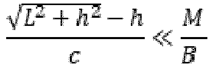
- For each individual beamformer, over each sub-band, the philosophy of the narrow-band beamformer may be applied, as described above.
- In the case of an OFDM receiver, the multiple paths will experience a delay spread. In this case, the receiver will exhibit the following properties:
- One single band.
- Fixed beamformer, forming a static wide beam, which is wide enough to receive all rays from the window.
- Once captured, the multiple staggered rays will be correctly received by the baseband processor, if the delay spread falls within the cyclic prefix, which typically for a millimetre wave system (5G NR) may be 586ns.
- Then the OFDM equalizer can recombine the received paths in the frequency-domain, achieving the same benefit described above in relation to the case of a Multi-band receiver.
- This is the most complex case, in which the beamformer may comprise multiple V-length finite impulse response (FIR) filters (instead of complex weights) whose outputs may then be combined. Then the problem becomes choosing the optimum V ∗ N coefficients of the filter. The problem can still be resolved by imposing a similar (yet more complicated formula) to that described above, or by using an adaptive filter.
- Embodiments of this disclosure may, for example, make use of the Metaradomes described in E. Özi, A. V. Osipov, T. F. Eibert, Metamaterials for Microwave Radomes and the Concept of a Metaradome: Review of the Literature to implement the

elements 2 described herein.Chapter 2 of this paper describes a radome as a protective cover between an antenna and its surroundings. It describes an ideal radome as fully transparent and lossless. A non-ideal radome can exhibit boresight error, caused by refraction of electromagnetic waves at the nonparallel interior and exterior sides of the radome wall with the result that a target is seen at an angularly changed, wrong position with respect to the antenna. The paper then describes the concept of metasurfaces, metasheets and metafilms, depending on whether the layer is penetrable or not, as well as the tunable materials including electrical tuning. It describes Huygens' metasheets that behave like a lens by locally controlling electric and magnetic currents induced on the surface. Inchapter 7, this paper then goes on to describe metaradomes that use metasurfaces/sheets/films to improve the electromagnetic response of the enclosed antenna and eliminate the negative effects of conventional microwave radomes. This includes active radomes that are externally controlled. The potential applications described in the paper (see chapter 9) are around radomes with tailored transmission, absorption, and reflection properties to bring additional features and benefits such as correction of phase distortions, reduction of transmission losses, shaping the frequency dependence of the transmission, and making the radome tunable, including the ability of being switched on/off. - Embodiments of this disclosure may use similar metasheet/metafilm concepts, including electronically tunable surfaces to implement the
elements 20. Note that embodiments of this disclosure relate to an application / use case which is not considered in E. Özi, A. V. Osipov, T. F. Eibert, Metamaterials for Microwave Radomes and the Concept of a Metaradome: Review of the Literature.
- Embodiments of this disclosure may be applied for any transceiver or communication system that implements communication through a barrier that can be transformed into an RF lens. Practical use may be limited to mmWave (and higher frequency) systems for which physical dimensions apply. One use case is a mmWave communications (Fixed Wireless Access/FWA) client use, where the device implements a 5G CPE/client modem. In conventional Fixed Wireless Access systems, a mmWave FWA modem is typically located outside of the customer premises with an Ethernet cable feeding into the house for further (WiFi based) distribution of the Internet connection. Embodiments of this disclosure can allow the modem to be placed inside of the customer premises, whereby a barrier (such as a wall, window or roof) is located in between the receive antenna array of the
receiver node 2 and thetransmitter node 4. According to embodiments of this disclosure, the losses associated with this barrier may be compensated for by the focusing effect described herein and a sufficient link budget may be maintained for successful communications. -
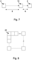
Figure 7 again shows an arrangement of atransmitter node 4, barrier 10 (e.g. a window, wall or roof) and areceiver node 2 according to an embodiment of this disclosure. Again, it is assumed that thedistance 8 between thetransmitter node 4 and thebarrier 10 is generally much larger than thedistance 6 between thebarrier 10 and thereceiver node 2. - In the present specific, yet illustrative, example, we assume the following parameters:
- distance between gNB and Lens: 100 meters;
- distance between lens formed by the
barrier 10 and the receiver node 2: 1 meter; - size of barrier (window in this example): 1×1m;
- operating frequency band: 28GHz (wavelength ~= 1cm); and
- size of receiver area of the receiver node 2: 0.1×0.1m (we also assume around 100 Antenna Elements spaced at λ/2).
- As a result, of these parameters, the following assumptions:
- the
receiver node 2 operates in the far-field; and - the incident wave from
transmitter node 4 to thereceiver node 2 approximates a parallel wave. - In this example, the barrier (e.g. window) may be sub-divided into
sub-arrays 22 as shown inFigure 8 . In the present example, the array ofsub-arrays 22 is a 10×10 square array, although this is not essential. In this example, the size of the sub-arrays may be defined as being substantially equal to the size of the receive antenna array of thereceiver node 2. This may be done for two reasons: - the complexity of the system is lower when the number of sub-arrays is smaller; and
- assuming that each sub-array provides a diffraction in a single direction, the lens effect is achieved inter-sub-array, not intra-sub-array.
- As a result, in this example, a total sub-array size that is larger than the receive antenna of the
receiver node 2 would result in RF energy loss. - As shown in
Figure 9 , each sub-array 102 may be implemented by a stacked set ofelements 104. Each element in the sub-array shown inFigure 9 may be considered to be a sub-wavelength resonant cell that implements the meta-material (e.g. see T. Jiang, Z. Wang, D. Li, J. Pan, B. Zhang, J. Huangfu, Y. Salamin, C. Li and L. Ran, "Low-DC Voltage-Controlled Steering-Antenna Radome Utilizing Tunable Active Metamaterial" IEEE Transactions on microwave theory and techniques, , which is incorporated herein by reference). - As shown in
Figure 10 , the combined sub-arrays can provide the lens operation.Figure 10 also shows how the size of each sub-array 22 may be matched to (or made smaller than) the size of the receive antenna of thereceiver node 2. -
Figure 11A shows anelement 20 of a sub-array 22 of the kind described above according to an embodiment of this disclosure.Figure 11B shows an equivalent circuit of the arrangement ofFigure 11A according to an embodiment of this disclosure. - In some embodiments, the elements may be passive elements, which refract the electromagnetic radiation be a fixed amount for focusing the electromagnetic radiation on a fixed location. However, as shown in
Figures 11A and 11B , in some embodiments at least some of the elements may be active elements in the sense that they support tunability of the refraction angle that the produce. This can allow the focus point provided by the barrier and elements to be tuned, offering the user more flexibility with respect to the location of the receive antenna of thereceiver node 2. - To support this tunability, each
element 20 may include one ormore microwave varactors 40. Thevaractors 40 may be used to tune the capacitance across pairs ofcapacitor plates 41 of theelement 20, thereby to alter the refraction angle produced by thatparticular element 20. A controller may be provided for controlling the varactor(s) 40 of eachrespective element 20 in thebarrier 10, collectively to cause theelements 20 to focus the electromagnetic radiation on a desired location in the customer premises. Thecapacitor plates 41 may, in some examples, be provided on opposite sides of the barrier (e.g. on opposite surfaces of aglass pane 30 of a window). In the embodiment shown inFigure 11A , each element comprises twomicrowave varactors 40 connected between pairs ofcapacitor plates 41, viainductive connections 43. A bias voltage Vbias and be applied across eachcapacitor plate 41 pair. Again, the bias voltage Vbias for eachelement 20 may be tunably controlled by the aforementioned controller. An equivalent circuit of the arrangement ofFigure 11A is shown inFigure 11B , according to an embodiment of this disclosure. InFigure 11B , thecapacitors 44 correspond to thecapacitor plates 41 shown inFigure 11A , while theinductors 42 correspond to theinductive connections 43. As can be seen inFigure 11B , each varactor may be coupled in series with theinductors 42. - Implementation of the resonant cells can be done using various materials including etched PCB with soldered discrete varactors mounted to a PCB or on a Transparent Conducting Film (TCF).
- Accordingly, there has been described a wireless communication system and method. The system comprises user equipment comprising a receive antenna for receiving mmWave signals from a base station transmitter. The system also includes a barrier configured to focus electromagnetic radiation carrying the mmWave signals onto the receive antenna of the user equipment.
- Although particular embodiments of this disclosure have been described, it will be appreciated that many modifications/additions and/or substitutions may be made within the scope of the claims.
Claims (15)
- A wireless communication system comprising:user equipment comprising a receive antenna for receiving mmWave signals from a base station transmitter; anda barrier configured to focus electromagnetic radiation carrying said mmWave signals onto the receive antenna of the user equipment.
- The wireless communication system of claim 1, wherein the barrier comprises a window for a building.
- The wireless communication system of claim 1 or claim 2, wherein the barrier comprises an array of elements, wherein each element is configured to refract the electromagnetic radiation carrying said mmWave signals by a respective angle, for collectively focusing the electromagnetic radiation carrying said mmWave signals onto the receive antenna of the user equipment.
- The wireless communication system of claim 3 when dependant on claim 2, wherein at least some of the elements are located on a surface of the window.
- The wireless communication system of claim 3 or claim 4, wherein at least some of the elements are passive elements.
- The wireless communication system of any of claims 3 to 5, wherein at least some of the elements are active elements.
- The wireless communication system of claim 6, wherein the active elements comprise a varactor for tuning a refraction angle applied by each active element to the electromagnetic radiation carrying said mmWave signals.
- The wireless communication system of any preceding claim, wherein a surface area of the barrier is larger than a surface area of the receive antenna of the user equipment.
- The wireless communication system of any preceding claim, wherein the user equipment comprises a fixed wireless access modem.
- The wireless communication system of any of claims 1 to 8, wherein the user equipment comprises a mobile communications device.
- The wireless communication system of any preceding claim further comprising said base station.
- A wireless communication method comprising:providing user equipment comprising a receive antenna;providing a barrier configured to focus electromagnetic radiation carrying mmWave signals onto the receive antenna of the user equipment; andreceiving mmWave signals at the user equipment by using the barrier to focus electromagnetic radiation carrying the mmWave signals onto the receive antenna of the user equipment, wherein the electromagnetic radiation carrying the mmWave signals is transmitted by a base station.
- The wireless communication method of claim 12, wherein the barrier comprises an array of elements, wherein each element refracts the electromagnetic radiation carrying said mmWave signals by a respective angle, for collectively focusing the electromagnetic radiation carrying said mmWave signals onto the receive antenna of the user equipment.
- The wireless communication method of claim 13, wherein the barrier comprises a window, and wherein at least some of the elements are located on a surface of the window.
- The wireless communication method of claim 13 or claim 14, wherein at least some of the elements are active elements including a varactor, and wherein the method further comprises using the varactor of each element to tune a refraction angle applied by each active element to the electromagnetic radiation carrying said mmWave signals.
Applications Claiming Priority (1)
| Application Number | Priority Date | Filing Date | Title |
|---|---|---|---|
| RO202000575 | 2020-09-11 |
Publications (1)
| Publication Number | Publication Date |
|---|---|
| EP3968453A1 true EP3968453A1 (en) | 2022-03-16 |
Family
ID=77358148
Family Applications (1)
| Application Number | Title | Priority Date | Filing Date |
|---|---|---|---|
| EP21191459.3A Withdrawn EP3968453A1 (en) | 2020-09-11 | 2021-08-16 | Wireless communication system and method |
Country Status (2)
| Country | Link |
|---|---|
| US (1) | US11881624B2 (en) |
| EP (1) | EP3968453A1 (en) |
Cited By (1)
| Publication number | Priority date | Publication date | Assignee | Title |
|---|---|---|---|---|
| EP4679632A1 (en) * | 2024-07-12 | 2026-01-14 | Airspan IP Holdco LLC | Enhancing outdoor-indoor penetration of wireless signals |
Families Citing this family (3)
| Publication number | Priority date | Publication date | Assignee | Title |
|---|---|---|---|---|
| EP4014281A4 (en) * | 2019-08-12 | 2023-09-13 | Metawave Corporation | Meta-structure wireless infrastructure for beamforming systems |
| US11445509B1 (en) * | 2021-04-30 | 2022-09-13 | Qualcomm Incorporated | Downlink beam management using a configurable deflector |
| US12315991B2 (en) * | 2022-12-14 | 2025-05-27 | Qualcomm Incorporated | Metasurface enabled in-vehicle link enhancement |
Citations (1)
| Publication number | Priority date | Publication date | Assignee | Title |
|---|---|---|---|---|
| US20190067826A1 (en) * | 2017-08-29 | 2019-02-28 | Metawave Corporation | Smart infrastructure sensing and communication system |
Family Cites Families (5)
| Publication number | Priority date | Publication date | Assignee | Title |
|---|---|---|---|---|
| US8797211B2 (en) | 2011-02-10 | 2014-08-05 | International Business Machines Corporation | Millimeter-wave communications using a reflector |
| US10236574B2 (en) * | 2013-12-17 | 2019-03-19 | Elwha Llc | Holographic aperture antenna configured to define selectable, arbitrary complex electromagnetic fields |
| US10720712B2 (en) * | 2016-09-22 | 2020-07-21 | Huawei Technologies Co., Ltd. | Liquid-crystal tunable metasurface for beam steering antennas |
| US11070269B2 (en) * | 2019-08-01 | 2021-07-20 | Samsung Electronics Co., Ltd. | Method and apparatus for transmitting or receiving signals in wireless communication system |
| US11152991B2 (en) * | 2020-01-23 | 2021-10-19 | Nxgen Partners Ip, Llc | Hybrid digital-analog mmwave repeater/relay with full duplex |
-
2021
- 2021-07-27 US US17/443,601 patent/US11881624B2/en active Active
- 2021-08-16 EP EP21191459.3A patent/EP3968453A1/en not_active Withdrawn
Patent Citations (1)
| Publication number | Priority date | Publication date | Assignee | Title |
|---|---|---|---|---|
| US20190067826A1 (en) * | 2017-08-29 | 2019-02-28 | Metawave Corporation | Smart infrastructure sensing and communication system |
Non-Patent Citations (5)
| Title |
|---|
| D. LIJ. PANB. ZHANGJ. HUANGFUY. SALAMINC. LIL. RAN: "Low-DC Voltage-Controlled Steering-Antenna Radome Utilizing Tunable Active Metamaterial", IEEE TRANSACTIONS ON MICROWAVE THEORY AND TECHNIQUES, vol. 60, no. 1, January 2012 (2012-01-01), XP011391038, DOI: 10.1109/TMTT.2011.2171981 |
| E. ÖZI J,A. V. OSIPOVT. F. EIBERT: "Metamaterials for Microwave Radomes", CONCEPT OF A METARADOME: REVIEW OF THE LITERATURE |
| E. ÖZI JA. V. OSIPOVT. F. EIBERT,, METAMATERIALS FOR MICROWAVE RADOMES AND THE CONCEPT OF A METARADOME: REVIEW OF THE LITERATURE |
| E. OZIA. V. OSIPOVT. F. EIBERT: "Metamaterials for Microwave Radomes and the Concept of a Metaradome", REVIEW OF THE LITERATURE |
| TAO JIANG ET AL: "Low-DC Voltage-Controlled Steering-Antenna Radome Utilizing Tunable Active Metamaterial", IEEE TRANSACTIONS ON MICROWAVE THEORY AND TECHNIQUES, IEEE, USA, vol. 60, no. 1, 16 November 2011 (2011-11-16), pages 170 - 178, XP011391038, ISSN: 0018-9480, DOI: 10.1109/TMTT.2011.2171981 * |
Cited By (1)
| Publication number | Priority date | Publication date | Assignee | Title |
|---|---|---|---|---|
| EP4679632A1 (en) * | 2024-07-12 | 2026-01-14 | Airspan IP Holdco LLC | Enhancing outdoor-indoor penetration of wireless signals |
Also Published As
| Publication number | Publication date |
|---|---|
| US11881624B2 (en) | 2024-01-23 |
| US20220085514A1 (en) | 2022-03-17 |
Similar Documents
| Publication | Publication Date | Title |
|---|---|---|
| US11881624B2 (en) | Wireless communication system and method | |
| US11670863B2 (en) | Multibeam antenna designs and operation | |
| EP3149540B1 (en) | Lens with spatial mixed-order bandpass filter | |
| Rahmati et al. | Multiband metallic frequency selective surface with wide range of band ratio | |
| US20140118191A1 (en) | Controllable Directional Antenna Apparatus And Method | |
| US10992066B2 (en) | Broadband antenna | |
| US11276941B2 (en) | Broadband antenna | |
| EP4576429A1 (en) | Antenna structure, antenna, and base station | |
| Liu et al. | Back-to-back microstrip antenna fed with tunable power divider | |
| EP4381609A1 (en) | Full-sphere coverage enhancing devices | |
| So et al. | Multiband sector antenna with the same beamwidth employing multiple woodpile metamaterial reflectors | |
| CN110546761A (en) | Super-directional array of volumetric antenna elements for wireless device applications | |
| Ramaccia et al. | Inductive tri-band double element FSS for space applications | |
| Liu et al. | Compact-size electronically steerable parasitic array radiator antenna | |
| Clemente et al. | Multiple feed transmit-array antennas with reduced focal distance | |
| EP3883059B1 (en) | Antenna, microwave device and communication system | |
| Yahya et al. | Single-layer UWB FSS for enhancing the gain of UWB monopole antenna | |
| Eid et al. | Optimizing rotmen lens topologies for 5g wireless grids | |
| US12244062B2 (en) | Antenna gain enhancement using frequency selective surface | |
| Manzillo | Wideband and flat multibeam antenna solutions for ultrafast communications in millimeter band | |
| RU2659303C1 (en) | Satellite multi-band antenna unit | |
| Alzidani et al. | Design of Wideband Linearly Polarized 3-Bit Transmit-Array Antenna With Polarization Rotation Unit Cell | |
| KR20170010777A (en) | Lens with spatial mixed-order bandpass filter | |
| Sum et al. | Selection of unit cell size for RF energy harvesting metaresonator array | |
| Cella et al. | Mm-wave short range outdoor links with phased arrays |
Legal Events
| Date | Code | Title | Description |
|---|---|---|---|
| PUAI | Public reference made under article 153(3) epc to a published international application that has entered the european phase |
Free format text: ORIGINAL CODE: 0009012 |
|
| STAA | Information on the status of an ep patent application or granted ep patent |
Free format text: STATUS: THE APPLICATION HAS BEEN PUBLISHED |
|
| AK | Designated contracting states |
Kind code of ref document: A1 Designated state(s): AL AT BE BG CH CY CZ DE DK EE ES FI FR GB GR HR HU IE IS IT LI LT LU LV MC MK MT NL NO PL PT RO RS SE SI SK SM TR |
|
| STAA | Information on the status of an ep patent application or granted ep patent |
Free format text: STATUS: REQUEST FOR EXAMINATION WAS MADE |
|
| 17P | Request for examination filed |
Effective date: 20220916 |
|
| RBV | Designated contracting states (corrected) |
Designated state(s): AL AT BE BG CH CY CZ DE DK EE ES FI FR GB GR HR HU IE IS IT LI LT LU LV MC MK MT NL NO PL PT RO RS SE SI SK SM TR |
|
| STAA | Information on the status of an ep patent application or granted ep patent |
Free format text: STATUS: THE APPLICATION IS DEEMED TO BE WITHDRAWN |
|
| 18D | Application deemed to be withdrawn |
Effective date: 20220917 |