EP3968442B1 - Battery module, battery rack comprising same, and power storage device - Google Patents
Battery module, battery rack comprising same, and power storage device Download PDFInfo
- Publication number
- EP3968442B1 EP3968442B1 EP20885150.1A EP20885150A EP3968442B1 EP 3968442 B1 EP3968442 B1 EP 3968442B1 EP 20885150 A EP20885150 A EP 20885150A EP 3968442 B1 EP3968442 B1 EP 3968442B1
- Authority
- EP
- European Patent Office
- Prior art keywords
- fire extinguishing
- battery
- module
- module case
- unit
- Prior art date
- Legal status (The legal status is an assumption and is not a legal conclusion. Google has not performed a legal analysis and makes no representation as to the accuracy of the status listed.)
- Active
Links
Images


Classifications
-
- H—ELECTRICITY
- H01—ELECTRIC ELEMENTS
- H01M—PROCESSES OR MEANS, e.g. BATTERIES, FOR THE DIRECT CONVERSION OF CHEMICAL ENERGY INTO ELECTRICAL ENERGY
- H01M50/00—Constructional details or processes of manufacture of the non-active parts of electrochemical cells other than fuel cells, e.g. hybrid cells
- H01M50/10—Primary casings; Jackets or wrappings
- H01M50/14—Primary casings; Jackets or wrappings for protecting against damage caused by external factors
- H01M50/143—Fireproof; Explosion-proof
-
- H—ELECTRICITY
- H01—ELECTRIC ELEMENTS
- H01M—PROCESSES OR MEANS, e.g. BATTERIES, FOR THE DIRECT CONVERSION OF CHEMICAL ENERGY INTO ELECTRICAL ENERGY
- H01M10/00—Secondary cells; Manufacture thereof
- H01M10/60—Heating or cooling; Temperature control
- H01M10/65—Means for temperature control structurally associated with the cells
- H01M10/656—Means for temperature control structurally associated with the cells characterised by the type of heat-exchange fluid
- H01M10/6567—Liquids
-
- A—HUMAN NECESSITIES
- A62—LIFE-SAVING; FIRE-FIGHTING
- A62C—FIRE-FIGHTING
- A62C3/00—Fire prevention, containment or extinguishing specially adapted for particular objects or places
- A62C3/16—Fire prevention, containment or extinguishing specially adapted for particular objects or places in electrical installations, e.g. cableways
-
- A—HUMAN NECESSITIES
- A62—LIFE-SAVING; FIRE-FIGHTING
- A62C—FIRE-FIGHTING
- A62C35/00—Permanently-installed equipment
- A62C35/02—Permanently-installed equipment with containers for delivering the extinguishing substance
-
- H—ELECTRICITY
- H01—ELECTRIC ELEMENTS
- H01M—PROCESSES OR MEANS, e.g. BATTERIES, FOR THE DIRECT CONVERSION OF CHEMICAL ENERGY INTO ELECTRICAL ENERGY
- H01M10/00—Secondary cells; Manufacture thereof
- H01M10/60—Heating or cooling; Temperature control
- H01M10/61—Types of temperature control
- H01M10/613—Cooling or keeping cold
-
- H—ELECTRICITY
- H01—ELECTRIC ELEMENTS
- H01M—PROCESSES OR MEANS, e.g. BATTERIES, FOR THE DIRECT CONVERSION OF CHEMICAL ENERGY INTO ELECTRICAL ENERGY
- H01M10/00—Secondary cells; Manufacture thereof
- H01M10/60—Heating or cooling; Temperature control
- H01M10/62—Heating or cooling; Temperature control specially adapted for specific applications
- H01M10/627—Stationary installations, e.g. power plant buffering or backup power supplies
-
- H—ELECTRICITY
- H01—ELECTRIC ELEMENTS
- H01M—PROCESSES OR MEANS, e.g. BATTERIES, FOR THE DIRECT CONVERSION OF CHEMICAL ENERGY INTO ELECTRICAL ENERGY
- H01M50/00—Constructional details or processes of manufacture of the non-active parts of electrochemical cells other than fuel cells, e.g. hybrid cells
- H01M50/20—Mountings; Secondary casings or frames; Racks, modules or packs; Suspension devices; Shock absorbers; Transport or carrying devices; Holders
- H01M50/204—Racks, modules or packs for multiple batteries or multiple cells
- H01M50/207—Racks, modules or packs for multiple batteries or multiple cells characterised by their shape
- H01M50/211—Racks, modules or packs for multiple batteries or multiple cells characterised by their shape adapted for pouch cells
-
- H—ELECTRICITY
- H01—ELECTRIC ELEMENTS
- H01M—PROCESSES OR MEANS, e.g. BATTERIES, FOR THE DIRECT CONVERSION OF CHEMICAL ENERGY INTO ELECTRICAL ENERGY
- H01M50/00—Constructional details or processes of manufacture of the non-active parts of electrochemical cells other than fuel cells, e.g. hybrid cells
- H01M50/20—Mountings; Secondary casings or frames; Racks, modules or packs; Suspension devices; Shock absorbers; Transport or carrying devices; Holders
- H01M50/233—Mountings; Secondary casings or frames; Racks, modules or packs; Suspension devices; Shock absorbers; Transport or carrying devices; Holders characterised by physical properties of casings or racks, e.g. dimensions
- H01M50/24—Mountings; Secondary casings or frames; Racks, modules or packs; Suspension devices; Shock absorbers; Transport or carrying devices; Holders characterised by physical properties of casings or racks, e.g. dimensions adapted for protecting batteries from their environment, e.g. from corrosion
-
- H—ELECTRICITY
- H01—ELECTRIC ELEMENTS
- H01M—PROCESSES OR MEANS, e.g. BATTERIES, FOR THE DIRECT CONVERSION OF CHEMICAL ENERGY INTO ELECTRICAL ENERGY
- H01M50/00—Constructional details or processes of manufacture of the non-active parts of electrochemical cells other than fuel cells, e.g. hybrid cells
- H01M50/20—Mountings; Secondary casings or frames; Racks, modules or packs; Suspension devices; Shock absorbers; Transport or carrying devices; Holders
- H01M50/251—Mountings; Secondary casings or frames; Racks, modules or packs; Suspension devices; Shock absorbers; Transport or carrying devices; Holders specially adapted for stationary devices, e.g. power plant buffering or backup power supplies
-
- H—ELECTRICITY
- H01—ELECTRIC ELEMENTS
- H01M—PROCESSES OR MEANS, e.g. BATTERIES, FOR THE DIRECT CONVERSION OF CHEMICAL ENERGY INTO ELECTRICAL ENERGY
- H01M50/00—Constructional details or processes of manufacture of the non-active parts of electrochemical cells other than fuel cells, e.g. hybrid cells
- H01M50/20—Mountings; Secondary casings or frames; Racks, modules or packs; Suspension devices; Shock absorbers; Transport or carrying devices; Holders
- H01M50/258—Modular batteries; Casings provided with means for assembling
-
- H—ELECTRICITY
- H01—ELECTRIC ELEMENTS
- H01M—PROCESSES OR MEANS, e.g. BATTERIES, FOR THE DIRECT CONVERSION OF CHEMICAL ENERGY INTO ELECTRICAL ENERGY
- H01M50/00—Constructional details or processes of manufacture of the non-active parts of electrochemical cells other than fuel cells, e.g. hybrid cells
- H01M50/50—Current conducting connections for cells or batteries
- H01M50/572—Means for preventing undesired use or discharge
- H01M50/584—Means for preventing undesired use or discharge for preventing incorrect connections inside or outside the batteries
- H01M50/59—Means for preventing undesired use or discharge for preventing incorrect connections inside or outside the batteries characterised by the protection means
- H01M50/591—Covers
-
- H—ELECTRICITY
- H01—ELECTRIC ELEMENTS
- H01M—PROCESSES OR MEANS, e.g. BATTERIES, FOR THE DIRECT CONVERSION OF CHEMICAL ENERGY INTO ELECTRICAL ENERGY
- H01M2200/00—Safety devices for primary or secondary batteries
-
- H—ELECTRICITY
- H01—ELECTRIC ELEMENTS
- H01M—PROCESSES OR MEANS, e.g. BATTERIES, FOR THE DIRECT CONVERSION OF CHEMICAL ENERGY INTO ELECTRICAL ENERGY
- H01M2220/00—Batteries for particular applications
- H01M2220/10—Batteries in stationary systems, e.g. emergency power source in plant
-
- Y—GENERAL TAGGING OF NEW TECHNOLOGICAL DEVELOPMENTS; GENERAL TAGGING OF CROSS-SECTIONAL TECHNOLOGIES SPANNING OVER SEVERAL SECTIONS OF THE IPC; TECHNICAL SUBJECTS COVERED BY FORMER USPC CROSS-REFERENCE ART COLLECTIONS [XRACs] AND DIGESTS
- Y02—TECHNOLOGIES OR APPLICATIONS FOR MITIGATION OR ADAPTATION AGAINST CLIMATE CHANGE
- Y02E—REDUCTION OF GREENHOUSE GAS [GHG] EMISSIONS, RELATED TO ENERGY GENERATION, TRANSMISSION OR DISTRIBUTION
- Y02E60/00—Enabling technologies; Technologies with a potential or indirect contribution to GHG emissions mitigation
- Y02E60/10—Energy storage using batteries
Definitions
- the present disclosure relates to a battery module, and a battery rack and an energy storage system including the battery module.
- Secondary batteries which are highly applicable to various products and exhibit superior electrical properties such as high energy density, etc. are commonly used not only in portable devices but also in electric vehicles (EVs) or hybrid electric vehicles (HEVs) driven by electrical power sources.
- EVs electric vehicles
- HEVs hybrid electric vehicles
- the secondary battery is drawing attentions as a new energy source for enhancing environment friendliness and energy efficiency in that the use of fossil fuels can be reduced greatly and no byproduct is generated during energy consumption.
- Secondary batteries widely used at present include lithium ion batteries, lithium polymer batteries, nickel cadmium batteries, nickel hydrogen batteries, nickel zinc batteries and the like.
- An operating voltage of the unit secondary battery cell namely a unit battery cell, is about 2.5V to 4.5V. Therefore, if a higher output voltage is required, a plurality of battery cells may be connected in series to configure a battery pack. In addition, depending on the charge/discharge capacity required for the battery pack, a plurality of battery cells may be connected in parallel to configure a battery pack. Thus, the number of battery cells included in the battery pack may be variously set according to the required output voltage or the demanded charge/discharge capacity.
- an energy storage system may be configured to include at least one battery pack that includes at least one battery module.
- EP 4 009 414 discloses a battery pack comprising extinguishment unit.
- JP H 053 1207 discloses a fire extinguisher in sodium-sulfur battery.
- JP 6 103887 discloses an electric power storage system.
- CN 206 700 536 discloses a battery box automatic fire extinguishing device.
- the present disclosure is directed to providing a battery module, which may block a thermal runaway when the thermal runaway occurs, and a battery rack and an energy storage system including such a battery module.
- a battery module comprising: at least one battery cell; a module case configured to accommodate the at least one battery cell; a fire extinguishing unit disposed at least partially inside the module case and adapted to be connected to a fire extinguishing tank unit containing a fire extinguishing agent to inject the fire extinguishing agent directly into the module case when a thermal runaway or fire occurs in the at least one battery cell; and an insulation cover configured to cover the fire extinguishing unit at least partially and disposed at least partially inside the module case.
- the insulation cover is mounted to a rear surface of the module case, and the rear surface of the module case may have an insulation cover mounting portion so that the insulation cover is mounted thereto.
- the fire extinguishing unit may at least partially pass through the module case and be disposed at an inner side of the insulation cover inside the module case.
- the insulation cover includes a cover base mounted to the rear surface of the module case; a cover cap configured to protrude by a predetermined length into the module case from the cover base; and an injection guider formed at the cover cap to guide the fire extinguishing agent of the fire extinguishing unit to be injected.
- the insulation cover has a hot air hole formed in the cover cap and provided at a side opposite to the injection guider.
- the injection guider may include a plurality of guide ribs formed by a predetermined length along a longitudinal direction of the cover cap and disposed to be spaced apart from each other by a predetermined distance to form a plurality of openings.
- the fire extinguishing unit may include a unit body adapted to be connected to the fire extinguishing tank unit; and an injection nozzle provided to the unit body to inject the fire extinguishing agent toward the battery cell inside the module case.
- the injection nozzle may include a nozzle body connected to the unit body and having an injection hole for injecting the fire extinguishing agent; and a glass bulb provided to the nozzle body and configured to cover the injection hole, the glass bulb being separated from the injection hole or at least partially broken to open the injection hole when the inside of the module case is exposed to an internal gas above a predetermined temperature.
- the present disclosure provides a battery rack, comprising: at least one battery module according to the former embodiments; and a rack case configured to accommodate the at least one battery module.
- the present disclosure provides an energy storage system, comprising at least one battery rack according to the former embodiment.
- a battery module which may block a thermal runaway when the thermal runaway occurs due to an abnormal situation, and a battery rack and an energy storage system including such a battery module.
- FIG. 1 is a diagram for illustrating a battery module according to an embodiment of the present disclosure
- FIG. 2 is a rear perspective view showing the battery module of FIG. 1
- FIG. 3 is a partially exploded view showing the battery module of FIG. 1 .
- a battery module 10 may include a battery cell 100, a module case 200, a fire extinguishing unit 300 and an insulation cover 400.
- the battery cell 100 is a secondary battery and may be provided as a pouch-type secondary battery, a rectangular secondary battery or a cylindrical secondary battery.
- the battery cell 100 is a pouch-type secondary battery.
- One battery cell 100 or a plurality of battery cells 100 may be provided. Hereinafter, in this embodiment, it will be described that a plurality of battery cells 100 are provided.
- the module case 200 may accommodate the at least one battery cell 100 or the plurality of battery cells 100 therein.
- the module case 200 may have an accommodation space for accommodating the plurality of battery cells 100.
- the module case 200 may have an insulation cover mounting portion 205.
- the insulation cover mounting portion 205 is provided at the rear of the module case 200 and may have an opening of a predetermined size.
- An insulation cover 400 may be mounted to the insulation cover mounting portion 205 so that the fire extinguishing unit 300, explained later, is mounted through the insulation cover 400.
- the fire extinguishing unit 300 is at least partially disposed inside the module case 200 and is connected to a fire extinguishing tank unit T (see FIG. 13 ) containing a fire extinguishing agent, and the fire extinguishing unit 300 may inject the fire extinguishing agent directly into the module case 200 when a thermal runaway or fire occurs at the at least one battery cell 100.
- the fire extinguishing agent may be water.
- the fire extinguishing unit 300 may be connected to the fire extinguishing tank unit T through a fire extinguishing agent supply pipe 70.
- the fire extinguishing unit 300 may be disposed to be at least partially surrounded by the insulation cover 400, explained later, inside the module case 200. That is, the fire extinguishing unit 300 may at least partially pass through the module case 200 and be disposed at an inner side of the insulation cover 400, explained later, inside the module case 200.
- the fire extinguishing unit 300 injects the fire extinguishing agent directly into the module case 200, when a fire occurs at the battery cells 100 in the battery module 10, the fire may be extinguished more quickly and effectively at an early stage.
- FIG. 4 is an enlarged view showing a main part of the battery module of FIG. 3
- FIG. 5 is a partially exploded perspective view showing the battery module of FIG. 4
- FIGS. 6 and 7 are diagrams for illustrating an insulation cover of the battery module of FIG. 5
- FIG. 8 is a sectional view showing a main part of the battery module of FIG. 1 .
- the fire extinguishing unit 300 may include a unit body 310 and an injection nozzle 330.
- the unit body 310 may be connected to the fire extinguishing tank unit T (see FIG. 13 ). Specifically, the unit body 310 has an internal channel for storage and flow of the fire extinguishing agent and may be connected to the fire extinguishing tank unit T (see FIG. 13 ), explained later, through the fire extinguishing agent supply pipe 70.
- the injection nozzle 330 is provided to the unit body 310 and may be disposed at the inner side of the module case 200 to inject the fire extinguishing agent toward the battery cells 100 inside the module case 200.
- the injection nozzle 330 may include a nozzle body 331 and a glass bulb 333.
- the nozzle body 331 is connected to the unit body 310, and specifically, may be mounted to the unit body 310 to communicate with the internal channel of the unit body 310.
- the nozzle body 331 may have an injection hole 332.
- the injection hole 332 is for injection of the fire extinguishing agent and may communicate with the internal channel of the unit body 310. When the injection hole 332 is opened, the fire extinguishing agent may be injected to the outside.
- the glass bulb 333 is provided to the nozzle body 331 and is configured to cover the injection hole 332. Also, when the module case 200 is exposed to an internal gas above a predetermined temperature, the glass bulb 333 may be configured to be separated from the injection hole 332 or at least partially broken to open the injection hole 332.
- the glass bulb 333 is filled with a predetermined substance such as a predetermined liquid or gas.
- a predetermined material may have a property of increasing the volume as the temperature increases.
- the glass bulb 333 may be broken due to the volume expansion of the predetermined material, melted, or separated from the nozzle body 331 above a predetermined temperature, for example 70°C to 100°C or higher to open the injection hole 332.
- the insulation cover 400 is for protecting the fire extinguishing unit 300 and may be configured to cover the fire extinguishing unit 300 at least partially. Also, the insulation cover 400 may be at least partially disposed inside the module case 200. Specifically, the insulation cover 400 is mounted to a rear surface of the module case 200 and may be disposed to cover the injection nozzle 330 of the fire extinguishing unit 300 at least partially.
- the insulation cover 400 may be made of an insulating material. By means of the insulation cover 400, it is possible to secure insulation between the fire extinguishing unit 300 and an internal circuit or the like inside the module case 200.
- the insulation cover 400 includes a cover base 410, a cover cap 430, an injection guider 450, and a hot air hole 470.
- the cover base 410 is mounted to the rear surface of the module case 200. Specifically, the cover base 410 may be mounted to the insulation cover mounting portion 205 of the module case 200.
- the cover cap 430 protrudes into the module case 200 from the cover base 410 by a predetermined length and may at least partially cover the injection nozzle 330 of the fire extinguishing unit 300.
- the injection guider 450 is formed at the cover cap 430 and guides the fire extinguishing agent of the fire extinguishing unit 300 to be injected.
- the injection guider 450 may be formed to open a front part and a side part of the cover cap 430.
- the injection guider 450 may include a plurality of guide ribs 455.
- the plurality of guide ribs 455 may be formed to have a predetermined length along a longitudinal direction of the cover cap 430, and may be spaced apart from each other by a predetermined distance to form a plurality of openings.
- the plurality of guide ribs 455 may guide air to be introduced into the cover cap 430 and guide the injection of the fire extinguishing agent when the fire extinguishing agent, explained later, is injected.
- the hot air hole 470 is formed in the cover cap 430 and is provided at a side opposite to the injection guider 450. At least one hot air hole 470 or a plurality of hot air holes 470 may be provided, and the hot air hole 470 may be provided in a hole shape of a predetermined size.
- the hot air hole 470 may function as a hot air passage to ensure smooth heat transfer within the cover cap 430 of the insulation cover 400. When a thermal runaway, explained later, occurs, the hot air hole 470 may secure smooth heat transfer inside the cover cap 430 of the insulation cover 400, which may guide the glass bulb 333 to be broken, melted or separated over a predetermined temperature more quickly so that the injection hole 332 is opened for injection of the fire extinguishing agent.
- the battery module 10 may include a cooling air discharge unit 500 and a cooling air supply unit 600.
- the cooling air discharge unit 500 is disposed to be spaced apart from the insulation cover 400 and the fire extinguishing unit 300 by a predetermined distance, and may be formed at the rear surface of the module case 200.
- the cooling air discharge unit 500 may be provided at a side opposite to the insulation cover mounting portion 205.
- a lower end of the cooling air discharge unit 500 may be provided to have a predetermined height from a lower end of the rear surface of the module case 200.
- the cooling air discharge unit 500 has a plurality of discharge holes and may be provided above the predetermined height. Accordingly, when the fire extinguishing agent is injected into the module case 200, explained later, it is possible to secure a predetermined water level at which the fire extinguishing agent may be filled up to the predetermined height inside the module case 200, thereby suppressing the thermal runaway or fire situation more effectively.
- the cooling air supply unit 600 is provided at the front of the module case 200, and may supply a cooling air into the module case 200 of the battery module 10 in order to cool the battery cells 100.
- the cooling air supply unit 600 may be disposed diagonally to the cooling air discharge unit 500 in order to increase the cooling circulation efficiency.
- FIGS. 9 to 11 are diagrams for illustrating a fire extinguishing agent injection mechanism inside a module case when a thermal runaway or fire occurs in the battery module of FIG. 1 .
- a fire situation or a thermal runaway situation caused by overheating or the like may occur at the battery cells 100 inside the module case 200 of the battery module 10, due to an abnormal situation of at least one battery cell 100. If the fire or thermal runaway situation occurs, a high-temperature gas G may be generated inside the module case 200 due to an overheated battery cell 100.
- the glass bulb 333 of the fire extinguishing unit 300 Due to the high-temperature gas G, the glass bulb 333 of the fire extinguishing unit 300 is broken or melted, or the glass bulb 333 is separated from the nozzle body 331, thereby opening the injection hole 332 so that the fire extinguishing agent may be injected. As the injection hole 332 is opened, the fire extinguishing agent W, namely water W, inside the fire extinguishing unit 300 may be immediately and directly injected toward the battery cells 100.
- the fire extinguishing agent when a fire situation or a thermal runaway situation occurs in the battery module 10, the fire extinguishing agent is immediately and directly injected toward the battery cells 100 inside the module case 200 by means of the fire extinguishing unit 300, thereby suppressing the fire situation or the thermal runaway situation more quickly at an early stage.
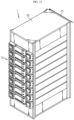
- FIG. 12 is a diagram for illustrating a battery rack according to an embodiment of the present disclosure.
- a battery rack 1 may include a plurality of battery modules 10 of the former embodiment, a rack case 50 for accommodating the plurality of battery modules 10, and a fire extinguishing agent supply pipe 70 connected to the plurality of battery modules 10.
- the fire extinguishing agent supply pipe 70 may communicate with the fire extinguishing unit 300 and the fire extinguishing tank unit T (see FIG. 13 ), explained later, so that when an abnormal situation such as fire occurs in at least one of the plurality of battery modules 10, the fire extinguishing agent of the extinguishing tank unit T may be guided to be supplied toward the battery module 10 where the abnormal situation has occurred.
- the battery rack 1 may have all the advantages of the battery module 10 of the former embodiment.
- FIG. 13 is a diagram for illustrating an energy storage system according to an embodiment of the present disclosure.
- an energy storage system E may be used for home or industrial use, as an energy source.
- the energy storage system E may include at least one battery rack 1 of the former embodiment, or a plurality of battery racks 1 in the case of this embodiment, and a rack container C for accommodating the plurality of battery racks 1.
- the rack container C may include the fire extinguishing tank unit T for supplying the fire extinguishing agent to the plurality of battery racks 1.
- the fire extinguishing tank unit T is filled with the fire extinguishing agent, namely water.
- the fire extinguishing tank unit T may be connected to the plurality of battery racks 1 through the fire extinguishing agent supply pipe 70 to supply the fire extinguishing water toward the plurality of battery racks 1.
- the energy storage system E since the energy storage system E according to this embodiment includes the battery rack 1 of the former embodiment, the energy storage system E may have all the advantages of the battery rack 1 of the former embodiment.
- a battery module 10 capable of extinguishing a thermal runaway or fire more quickly at an early stage more quickly when a thermal runaway occurs inside the battery module 10 or a fire occurs due to the thermal runaway, and to provide a battery rack 1 including the battery module 10 and an energy storage system E including the battery rack 1.
Landscapes
- Chemical & Material Sciences (AREA)
- Chemical Kinetics & Catalysis (AREA)
- Electrochemistry (AREA)
- General Chemical & Material Sciences (AREA)
- Engineering & Computer Science (AREA)
- Manufacturing & Machinery (AREA)
- Health & Medical Sciences (AREA)
- Public Health (AREA)
- Business, Economics & Management (AREA)
- Emergency Management (AREA)
- Battery Mounting, Suspending (AREA)
- Secondary Cells (AREA)
Description
- The present disclosure relates to a battery module, and a battery rack and an energy storage system including the battery module.
- The present application claims priority to
Korean Patent Application No. 10-2019-0142955 filed on November 8, 2019 - Secondary batteries which are highly applicable to various products and exhibit superior electrical properties such as high energy density, etc. are commonly used not only in portable devices but also in electric vehicles (EVs) or hybrid electric vehicles (HEVs) driven by electrical power sources. The secondary battery is drawing attentions as a new energy source for enhancing environment friendliness and energy efficiency in that the use of fossil fuels can be reduced greatly and no byproduct is generated during energy consumption.
- Secondary batteries widely used at present include lithium ion batteries, lithium polymer batteries, nickel cadmium batteries, nickel hydrogen batteries, nickel zinc batteries and the like. An operating voltage of the unit secondary battery cell, namely a unit battery cell, is about 2.5V to 4.5V. Therefore, if a higher output voltage is required, a plurality of battery cells may be connected in series to configure a battery pack. In addition, depending on the charge/discharge capacity required for the battery pack, a plurality of battery cells may be connected in parallel to configure a battery pack. Thus, the number of battery cells included in the battery pack may be variously set according to the required output voltage or the demanded charge/discharge capacity.
- Meanwhile, when a plurality of battery cells are connected in series or in parallel to configure a battery pack, it is common to configure a battery module including at least one battery cell first, and then configure a battery pack by using at least one battery module and adding other components. Here, according to various voltage and capacity requirements, an energy storage system may be configured to include at least one battery pack that includes at least one battery module.
- In the conventional battery module, when a thermal runaway occurs in the battery module, the thermal runaway is continuously transferred among the battery cells inside the battery module, thereby damaging all battery cells.
- Therefore, there is a need to find a technique for blocking a thermal runaway when the thermal runaway occurs.
EP 4 009 414 discloses a battery pack comprising extinguishment unit.JP H 053 1207 JP 6 103887 CN 206 700 536 discloses a battery box automatic fire extinguishing device. - The present disclosure is directed to providing a battery module, which may block a thermal runaway when the thermal runaway occurs, and a battery rack and an energy storage system including such a battery module.
- In one aspect of the present disclosure, there is provided a battery module, comprising: at least one battery cell; a module case configured to accommodate the at least one battery cell; a fire extinguishing unit disposed at least partially inside the module case and adapted to be connected to a fire extinguishing tank unit containing a fire extinguishing agent to inject the fire extinguishing agent directly into the module case when a thermal runaway or fire occurs in the at least one battery cell; and an insulation cover configured to cover the fire extinguishing unit at least partially and disposed at least partially inside the module case.
- The insulation cover is mounted to a rear surface of the module case, and the rear surface of the module case may have an insulation cover mounting portion so that the insulation cover is mounted thereto.
- The fire extinguishing unit may at least partially pass through the module case and be disposed at an inner side of the insulation cover inside the module case.
- The insulation cover includes a cover base mounted to the rear surface of the module case; a cover cap configured to protrude by a predetermined length into the module case from the cover base; and an injection guider formed at the cover cap to guide the fire extinguishing agent of the fire extinguishing unit to be injected.
- The insulation cover has a hot air hole formed in the cover cap and provided at a side opposite to the injection guider.
- The injection guider may include a plurality of guide ribs formed by a predetermined length along a longitudinal direction of the cover cap and disposed to be spaced apart from each other by a predetermined distance to form a plurality of openings.
- The fire extinguishing unit may include a unit body adapted to be connected to the fire extinguishing tank unit; and an injection nozzle provided to the unit body to inject the fire extinguishing agent toward the battery cell inside the module case.
- The injection nozzle may include a nozzle body connected to the unit body and having an injection hole for injecting the fire extinguishing agent; and a glass bulb provided to the nozzle body and configured to cover the injection hole, the glass bulb being separated from the injection hole or at least partially broken to open the injection hole when the inside of the module case is exposed to an internal gas above a predetermined temperature.
- In addition, the present disclosure provides a battery rack, comprising: at least one battery module according to the former embodiments; and a rack case configured to accommodate the at least one battery module.
- Moreover, the present disclosure provides an energy storage system, comprising at least one battery rack according to the former embodiment.
- According to various embodiments as above, it is possible to provide a battery module, which may block a thermal runaway when the thermal runaway occurs due to an abnormal situation, and a battery rack and an energy storage system including such a battery module.
-
-
FIG. 1 is a diagram for illustrating a battery module according to an embodiment of the present disclosure. -
FIG. 2 is a rear perspective view showing the battery module ofFIG. 1 . -
FIG. 3 is a partially exploded view showing the battery module ofFIG. 1 . -
FIG. 4 is an enlarged view showing a main part of the battery module ofFIG. 3 . -
FIG. 5 is a partially exploded perspective view showing the battery module ofFIG. 4 . -
FIGS. 6 and 7 are diagrams for illustrating an insulation cover of the battery module ofFIG. 5 . -
FIG. 8 is a sectional view showing a main part of the battery module ofFIG. 1 . -
FIGS. 9 to 11 are diagrams for illustrating a fire extinguishing agent injection mechanism inside a module case when a thermal runaway or fire occurs in the battery module ofFIG. 1 . -
FIG. 12 is a diagram for illustrating a battery rack according to an embodiment of the present disclosure. -
FIG. 13 is a diagram for illustrating an energy storage system according to an embodiment of the present disclosure. - The present disclosure will become more apparent by describing in detail the embodiments of the present disclosure with reference to the accompanying drawings. It should be understood that the embodiments disclosed herein are illustrative only for better understanding of the present disclosure, and that the present disclosure may be modified in various ways. In addition, for ease understanding of the present disclosure, the accompanying drawings are not drawn to real scale, but the dimensions of some components may be exaggerated.
-
FIG. 1 is a diagram for illustrating a battery module according to an embodiment of the present disclosure,FIG. 2 is a rear perspective view showing the battery module ofFIG. 1 , andFIG. 3 is a partially exploded view showing the battery module ofFIG. 1 . - Referring to
FIGS. 1 to 3 , abattery module 10 may include abattery cell 100, amodule case 200, afire extinguishing unit 300 and aninsulation cover 400. - The
battery cell 100 is a secondary battery and may be provided as a pouch-type secondary battery, a rectangular secondary battery or a cylindrical secondary battery. Hereinafter, in this embodiment, it will be described that thebattery cell 100 is a pouch-type secondary battery. - One
battery cell 100 or a plurality ofbattery cells 100 may be provided. Hereinafter, in this embodiment, it will be described that a plurality ofbattery cells 100 are provided. - The
module case 200 may accommodate the at least onebattery cell 100 or the plurality ofbattery cells 100 therein. For this, themodule case 200 may have an accommodation space for accommodating the plurality ofbattery cells 100. - The
module case 200 may have an insulationcover mounting portion 205. - The insulation
cover mounting portion 205 is provided at the rear of themodule case 200 and may have an opening of a predetermined size. Aninsulation cover 400 may be mounted to the insulationcover mounting portion 205 so that thefire extinguishing unit 300, explained later, is mounted through theinsulation cover 400. - The
fire extinguishing unit 300 is at least partially disposed inside themodule case 200 and is connected to a fire extinguishing tank unit T (seeFIG. 13 ) containing a fire extinguishing agent, and thefire extinguishing unit 300 may inject the fire extinguishing agent directly into themodule case 200 when a thermal runaway or fire occurs at the at least onebattery cell 100. As an example, the fire extinguishing agent may be water. - The
fire extinguishing unit 300 may be connected to the fire extinguishing tank unit T through a fire extinguishingagent supply pipe 70. Thefire extinguishing unit 300 may be disposed to be at least partially surrounded by theinsulation cover 400, explained later, inside themodule case 200. That is, thefire extinguishing unit 300 may at least partially pass through themodule case 200 and be disposed at an inner side of theinsulation cover 400, explained later, inside themodule case 200. - In this embodiment, since the
fire extinguishing unit 300 injects the fire extinguishing agent directly into themodule case 200, when a fire occurs at thebattery cells 100 in thebattery module 10, the fire may be extinguished more quickly and effectively at an early stage.. - Hereinafter, the
fire extinguishing unit 300 and theinsulation cover 400 covering thefire extinguishing unit 300 according to this embodiment will be described in more detail. -
FIG. 4 is an enlarged view showing a main part of the battery module ofFIG. 3 ,FIG. 5 is a partially exploded perspective view showing the battery module ofFIG. 4 ,FIGS. 6 and 7 are diagrams for illustrating an insulation cover of the battery module ofFIG. 5 , andFIG. 8 is a sectional view showing a main part of the battery module ofFIG. 1 . - Referring to
FIGS. 4 to 8 , thefire extinguishing unit 300 may include aunit body 310 and aninjection nozzle 330. - The
unit body 310 may be connected to the fire extinguishing tank unit T (seeFIG. 13 ). Specifically, theunit body 310 has an internal channel for storage and flow of the fire extinguishing agent and may be connected to the fire extinguishing tank unit T (seeFIG. 13 ), explained later, through the fire extinguishingagent supply pipe 70. - The
injection nozzle 330 is provided to theunit body 310 and may be disposed at the inner side of themodule case 200 to inject the fire extinguishing agent toward thebattery cells 100 inside themodule case 200. - The
injection nozzle 330 may include anozzle body 331 and aglass bulb 333. - The
nozzle body 331 is connected to theunit body 310, and specifically, may be mounted to theunit body 310 to communicate with the internal channel of theunit body 310. - The
nozzle body 331 may have aninjection hole 332. - The
injection hole 332 is for injection of the fire extinguishing agent and may communicate with the internal channel of theunit body 310. When theinjection hole 332 is opened, the fire extinguishing agent may be injected to the outside. - The
glass bulb 333 is provided to thenozzle body 331 and is configured to cover theinjection hole 332. Also, when themodule case 200 is exposed to an internal gas above a predetermined temperature, theglass bulb 333 may be configured to be separated from theinjection hole 332 or at least partially broken to open theinjection hole 332. - The
glass bulb 333 is filled with a predetermined substance such as a predetermined liquid or gas. Such a predetermined material may have a property of increasing the volume as the temperature increases. Specifically, theglass bulb 333 may be broken due to the volume expansion of the predetermined material, melted, or separated from thenozzle body 331 above a predetermined temperature, for example 70°C to 100°C or higher to open theinjection hole 332. - The
insulation cover 400 is for protecting thefire extinguishing unit 300 and may be configured to cover thefire extinguishing unit 300 at least partially. Also, theinsulation cover 400 may be at least partially disposed inside themodule case 200. Specifically, theinsulation cover 400 is mounted to a rear surface of themodule case 200 and may be disposed to cover theinjection nozzle 330 of thefire extinguishing unit 300 at least partially. - The
insulation cover 400 may be made of an insulating material. By means of theinsulation cover 400, it is possible to secure insulation between thefire extinguishing unit 300 and an internal circuit or the like inside themodule case 200. - The
insulation cover 400 includes acover base 410, acover cap 430, aninjection guider 450, and ahot air hole 470. - The
cover base 410 is mounted to the rear surface of themodule case 200. Specifically, thecover base 410 may be mounted to the insulationcover mounting portion 205 of themodule case 200. - The
cover cap 430 protrudes into themodule case 200 from thecover base 410 by a predetermined length and may at least partially cover theinjection nozzle 330 of thefire extinguishing unit 300. - The
injection guider 450 is formed at thecover cap 430 and guides the fire extinguishing agent of thefire extinguishing unit 300 to be injected. Theinjection guider 450 may be formed to open a front part and a side part of thecover cap 430. - The
injection guider 450 may include a plurality ofguide ribs 455. - The plurality of
guide ribs 455 may be formed to have a predetermined length along a longitudinal direction of thecover cap 430, and may be spaced apart from each other by a predetermined distance to form a plurality of openings. The plurality ofguide ribs 455 may guide air to be introduced into thecover cap 430 and guide the injection of the fire extinguishing agent when the fire extinguishing agent, explained later, is injected. - The
hot air hole 470 is formed in thecover cap 430 and is provided at a side opposite to theinjection guider 450. At least onehot air hole 470 or a plurality ofhot air holes 470 may be provided, and thehot air hole 470 may be provided in a hole shape of a predetermined size. - The
hot air hole 470 may function as a hot air passage to ensure smooth heat transfer within thecover cap 430 of theinsulation cover 400. When a thermal runaway, explained later, occurs, thehot air hole 470 may secure smooth heat transfer inside thecover cap 430 of theinsulation cover 400, which may guide theglass bulb 333 to be broken, melted or separated over a predetermined temperature more quickly so that theinjection hole 332 is opened for injection of the fire extinguishing agent. - Meanwhile, the
battery module 10 may include a coolingair discharge unit 500 and a coolingair supply unit 600. - The cooling
air discharge unit 500 is disposed to be spaced apart from theinsulation cover 400 and thefire extinguishing unit 300 by a predetermined distance, and may be formed at the rear surface of themodule case 200. - At the rear of the
module case 200, the coolingair discharge unit 500 may be provided at a side opposite to the insulationcover mounting portion 205. A lower end of the coolingair discharge unit 500 may be provided to have a predetermined height from a lower end of the rear surface of themodule case 200. - The cooling
air discharge unit 500 has a plurality of discharge holes and may be provided above the predetermined height. Accordingly, when the fire extinguishing agent is injected into themodule case 200, explained later, it is possible to secure a predetermined water level at which the fire extinguishing agent may be filled up to the predetermined height inside themodule case 200, thereby suppressing the thermal runaway or fire situation more effectively. - The cooling
air supply unit 600 is provided at the front of themodule case 200, and may supply a cooling air into themodule case 200 of thebattery module 10 in order to cool thebattery cells 100. The coolingair supply unit 600 may be disposed diagonally to the coolingair discharge unit 500 in order to increase the cooling circulation efficiency. - Hereinafter, the fire extinguishing agent injection mechanism inside the
module case 200 according to this embodiment when a fire or thermal runaway occurs in thebattery module 10 will be described in more detail. -
FIGS. 9 to 11 are diagrams for illustrating a fire extinguishing agent injection mechanism inside a module case when a thermal runaway or fire occurs in the battery module ofFIG. 1 . - Referring to
FIGS. 9 to 11 , a fire situation or a thermal runaway situation caused by overheating or the like may occur at thebattery cells 100 inside themodule case 200 of thebattery module 10, due to an abnormal situation of at least onebattery cell 100. If the fire or thermal runaway situation occurs, a high-temperature gas G may be generated inside themodule case 200 due to anoverheated battery cell 100. - Due to the high-temperature gas G, the
glass bulb 333 of thefire extinguishing unit 300 is broken or melted, or theglass bulb 333 is separated from thenozzle body 331, thereby opening theinjection hole 332 so that the fire extinguishing agent may be injected. As theinjection hole 332 is opened, the fire extinguishing agent W, namely water W, inside thefire extinguishing unit 300 may be immediately and directly injected toward thebattery cells 100. - Accordingly, in this embodiment, when a fire situation or a thermal runaway situation occurs in the
battery module 10, the fire extinguishing agent is immediately and directly injected toward thebattery cells 100 inside themodule case 200 by means of thefire extinguishing unit 300, thereby suppressing the fire situation or the thermal runaway situation more quickly at an early stage. - Therefore, in this embodiment, since the fire situation or the thermal runaway situation is suppressed more quickly at an early stage, it is possible to more effectively prevent the occurrence of a dangerous situation such as a secondary explosion caused by heat or flame transfer to neighboring
battery cells 100 in advance. -
FIG. 12 is a diagram for illustrating a battery rack according to an embodiment of the present disclosure. - Referring to
FIG. 12 , a battery rack 1 may include a plurality ofbattery modules 10 of the former embodiment, arack case 50 for accommodating the plurality ofbattery modules 10, and a fire extinguishingagent supply pipe 70 connected to the plurality ofbattery modules 10. - The fire extinguishing
agent supply pipe 70 may communicate with thefire extinguishing unit 300 and the fire extinguishing tank unit T (seeFIG. 13 ), explained later, so that when an abnormal situation such as fire occurs in at least one of the plurality ofbattery modules 10, the fire extinguishing agent of the extinguishing tank unit T may be guided to be supplied toward thebattery module 10 where the abnormal situation has occurred. - Since the battery rack 1 according to this embodiment includes the
battery module 10 of the former embodiment, the battery rack 1 may have all the advantages of thebattery module 10 of the former embodiment. -
FIG. 13 is a diagram for illustrating an energy storage system according to an embodiment of the present disclosure. - Referring to
FIG. 13 , an energy storage system E may be used for home or industrial use, as an energy source. The energy storage system E may include at least one battery rack 1 of the former embodiment, or a plurality of battery racks 1 in the case of this embodiment, and a rack container C for accommodating the plurality of battery racks 1. - The rack container C may include the fire extinguishing tank unit T for supplying the fire extinguishing agent to the plurality of battery racks 1. The fire extinguishing tank unit T is filled with the fire extinguishing agent, namely water. The fire extinguishing tank unit T may be connected to the plurality of battery racks 1 through the fire extinguishing
agent supply pipe 70 to supply the fire extinguishing water toward the plurality of battery racks 1. - Since the energy storage system E according to this embodiment includes the battery rack 1 of the former embodiment, the energy storage system E may have all the advantages of the battery rack 1 of the former embodiment.
- According to various embodiments as described above, it is possible to provide a
battery module 10 capable of extinguishing a thermal runaway or fire more quickly at an early stage more quickly when a thermal runaway occurs inside thebattery module 10 or a fire occurs due to the thermal runaway, and to provide a battery rack 1 including thebattery module 10 and an energy storage system E including the battery rack 1. - While the embodiments of the present disclosure have been shown and described, it should be understood that the present disclosure is not limited to the specific embodiments described, and that various changes and modifications can be made within the scope of the present disclosure by those skilled in the art, and these modifications should not be understood individually from the technical ideas and views of the present disclosure.
Claims (7)
- A battery module (10), comprising:at least one battery cell (100);a module case (200) configured to accommodate the at least one battery cell (100);a fire extinguishing unit (300) disposed at least partially inside the module case (200) and adapted to be connected to a fire extinguishing tank unit (T) containing a fire extinguishing agent to inject the fire extinguishing agent directly into the module case (200) when a thermal runaway or fire occurs in the at least one battery cell (100); andan insulation cover (400) configured to cover the fire extinguishing unit (300) at least partially and disposed at least partially inside the module case (200),wherein the insulation cover (400) is mounted to a rear surface of the module case (200), andthe rear surface of the module case (200) has an insulation cover mounting portion (205) so that the insulation cover (400) is mounted thereto,wherein the insulation cover (400) includes:a cover base (410) mounted to the rear surface of the module case (200);a cover cap (430) configured to protrude by a predetermined length into the module case (200) from the cover base (410); andan injection guider (450) formed at the cover cap (430) to guide the fire extinguishing agent of the fire extinguishing unit (300) to be injected,characterized in that the insulation cover (400) has a hot air hole (470) formed in the cover cap (430) and provided at a side opposite to the injection guider (450).
- The battery module (10) according to claim 1,
wherein the fire extinguishing unit (300) at least partially passes through the module case (200) and is disposed at an inner side of the insulation cover (400) inside the module case (200). - The battery module (10) according to claim 1,
wherein the injection guider (450) includes a plurality of guide ribs (455) formed by a predetermined length along a longitudinal direction of the cover cap (430) and disposed to be spaced apart from each other by a predetermined distance to form a plurality of openings. - The battery module according to claim 1,
wherein the fire extinguishing unit (300) includes:a unit body (310) adapted to be connected to the fire extinguishing tank unit (T); andan injection nozzle (330) provided to the unit body (310) to inject the fire extinguishing agent toward the battery cell (100) inside the module case. - The battery module (10) according to claim 4,
wherein the injection nozzle (330) includes:a nozzle body (331) connected to the unit body (310) and having an injection hole (332) for injecting the fire extinguishing agent; anda glass bulb (333) provided to the nozzle body (331) and configured to cover the injection hole (332), the glass bulb (333) being separated from the injection hole (332) or at least partially broken to open the injection hole (332) when the inside of the module case (200) is exposed to an internal gas above a predetermined temperature. - A battery rack (1), comprising:at least one battery module (10) as defined in claim 1; anda rack case (50) configured to accommodate the at least one battery module (10).
- An energy storage system, comprising at least one battery rack (1) as defined in claim 6
Applications Claiming Priority (2)
| Application Number | Priority Date | Filing Date | Title |
|---|---|---|---|
| KR20190142955 | 2019-11-08 | ||
| PCT/KR2020/015553 WO2021091329A1 (en) | 2019-11-08 | 2020-11-06 | Battery module, battery rack comprising same, and power storage device |
Publications (3)
| Publication Number | Publication Date |
|---|---|
| EP3968442A1 EP3968442A1 (en) | 2022-03-16 |
| EP3968442A4 EP3968442A4 (en) | 2023-11-01 |
| EP3968442B1 true EP3968442B1 (en) | 2025-01-01 |
Family
ID=75849008
Family Applications (1)
| Application Number | Title | Priority Date | Filing Date |
|---|---|---|---|
| EP20885150.1A Active EP3968442B1 (en) | 2019-11-08 | 2020-11-06 | Battery module, battery rack comprising same, and power storage device |
Country Status (9)
| Country | Link |
|---|---|
| US (2) | US12469906B2 (en) |
| EP (1) | EP3968442B1 (en) |
| JP (1) | JP7348316B2 (en) |
| KR (1) | KR102660831B1 (en) |
| CN (1) | CN217468561U (en) |
| ES (1) | ES3007207T3 (en) |
| HU (1) | HUE070055T2 (en) |
| PL (1) | PL3968442T3 (en) |
| WO (1) | WO2021091329A1 (en) |
Families Citing this family (9)
| Publication number | Priority date | Publication date | Assignee | Title |
|---|---|---|---|---|
| KR102858181B1 (en) | 2020-02-27 | 2025-09-10 | 주식회사 엘지에너지솔루션 | Battery module having a structure capable of rapid cooling and the Energy Storage System comprising the same |
| KR102861701B1 (en) * | 2021-07-16 | 2025-09-17 | 주식회사 엘지에너지솔루션 | Battery pack frame, battery rack and energy storage system comprising the battery pack frame |
| KR102808526B1 (en) * | 2021-07-16 | 2025-05-14 | 주식회사 엘지에너지솔루션 | Battery rack and energy storage system comprising the battery rack |
| WO2023121260A1 (en) * | 2021-12-22 | 2023-06-29 | 주식회사 엘지에너지솔루션 | Battery pack with improved safety |
| KR102685925B1 (en) * | 2021-12-27 | 2024-07-16 | 주식회사 엘지에너지솔루션 | Battery module, battery pack comprising the battery module, energy storage system and vehicle comprising the battery pack |
| EP4645516A4 (en) * | 2023-03-17 | 2026-04-29 | Lg Energy Solution Ltd | BATTERY DISCONNECTION UNIT WITH FIRE EXTINGUISHER LIQUID AND SECONDARY BATTERY SO THAT |
| KR20250010418A (en) * | 2023-07-12 | 2025-01-21 | 주식회사 엘지에너지솔루션 | Battery module |
| KR102681732B1 (en) * | 2023-09-07 | 2024-07-04 | 김원배 | Battery case for extinguishing fire of electric vehicle and firefighting connector for extinguishing fire of electric vehicle |
| CN117810568A (en) * | 2023-12-28 | 2024-04-02 | 中国华能集团清洁能源技术研究院有限公司 | Energy storage device based on thermal runaway protection |
Family Cites Families (24)
| Publication number | Priority date | Publication date | Assignee | Title |
|---|---|---|---|---|
| JPH0531207A (en) * | 1991-08-01 | 1993-02-09 | Ngk Insulators Ltd | Fire extinguisher in sodium-sulfur battery |
| JPH06132289A (en) | 1992-10-20 | 1994-05-13 | Hitachi Ltd | Semiconductor device |
| JPH08173570A (en) * | 1994-12-21 | 1996-07-09 | Senju Sprinkler Kk | Sprinkler head |
| KR200277800Y1 (en) | 2002-01-17 | 2002-06-14 | (주)이론와이어리스 | Alarm apparatus for vehicle velocity |
| KR200277300Y1 (en) * | 2002-03-12 | 2002-06-01 | 정인진 | Combined Structure of Sprinkler Head for Extinguishing a Fire |
| JP5161664B2 (en) * | 2008-06-12 | 2013-03-13 | ホーチキ株式会社 | Closed foam fire extinguishing head |
| JP2011115335A (en) | 2009-12-02 | 2011-06-16 | Ntt Facilities Inc | Rectification cylinder, and gas fire extinguishing system equipped with the same |
| WO2013036087A2 (en) * | 2011-09-08 | 2013-03-14 | 주식회사 엘지화학 | Apparatus for extinguishing a battery-pack fire |
| JP5953925B2 (en) | 2012-05-15 | 2016-07-20 | 三菱自動車工業株式会社 | Battery energy release device |
| JP6103887B2 (en) | 2012-11-01 | 2017-03-29 | ホーチキ株式会社 | Power storage system |
| US9821182B2 (en) * | 2013-11-19 | 2017-11-21 | Protector Safety Ind., Ltd. | Concealed sprinkler head cover adjusting device |
| JP2015220177A (en) | 2014-05-20 | 2015-12-07 | 株式会社Gsユアサ | Power storage device |
| JP2016092007A (en) * | 2014-10-29 | 2016-05-23 | 日本ドライケミカル株式会社 | Thermal runaway suppression system of secondary battery |
| US10125711B2 (en) | 2015-07-29 | 2018-11-13 | General Electric Company | Systems for fuel delivery |
| JP2019075191A (en) | 2016-03-08 | 2019-05-16 | パナソニックIpマネジメント株式会社 | Power storage device |
| KR101869036B1 (en) | 2016-06-20 | 2018-07-23 | 조광호 | Colling system of battery pack for electric vehicles |
| KR102184169B1 (en) | 2016-08-26 | 2020-11-27 | 주식회사 엘지화학 | Battery module |
| KR102053988B1 (en) | 2016-09-21 | 2019-12-09 | 주식회사 엘지화학 | Energy storage system and method of fire managing for the energy storage system |
| KR101866288B1 (en) | 2016-10-26 | 2018-06-12 | 주식회사 인팩 | Check Valve Having Fluid Controller |
| KR102708086B1 (en) | 2017-02-09 | 2024-09-19 | 주식회사 엘지에너지솔루션 | Fire protection system for a structure containing a battery |
| CN206700536U (en) | 2017-04-06 | 2017-12-05 | 江苏兴云新能源有限公司 | A kind of battery case automatic extinguishing device |
| KR102490611B1 (en) | 2018-01-12 | 2023-01-19 | 현대모비스 주식회사 | Battery system with fire-off function |
| KR20190142955A (en) | 2018-06-19 | 2019-12-30 | 오지영 | Heat conduction system for electric and electronic apparatus cooling |
| KR102775084B1 (en) | 2019-09-19 | 2025-02-27 | 주식회사 엘지에너지솔루션 | Battery Pack Having Fire Extinguishing Unit |
-
2020
- 2020-11-06 EP EP20885150.1A patent/EP3968442B1/en active Active
- 2020-11-06 PL PL20885150.1T patent/PL3968442T3/en unknown
- 2020-11-06 HU HUE20885150A patent/HUE070055T2/en unknown
- 2020-11-06 CN CN202090000735.3U patent/CN217468561U/en active Active
- 2020-11-06 KR KR1020200148116A patent/KR102660831B1/en active Active
- 2020-11-06 ES ES20885150T patent/ES3007207T3/en active Active
- 2020-11-06 JP JP2021574856A patent/JP7348316B2/en active Active
- 2020-11-06 US US17/609,993 patent/US12469906B2/en active Active
- 2020-11-06 WO PCT/KR2020/015553 patent/WO2021091329A1/en not_active Ceased
-
2025
- 2025-10-24 US US19/368,982 patent/US20260051579A1/en active Pending
Also Published As
| Publication number | Publication date |
|---|---|
| JP7348316B2 (en) | 2023-09-20 |
| EP3968442A1 (en) | 2022-03-16 |
| WO2021091329A1 (en) | 2021-05-14 |
| US20220209339A1 (en) | 2022-06-30 |
| JP2022536404A (en) | 2022-08-15 |
| US20260051579A1 (en) | 2026-02-19 |
| ES3007207T3 (en) | 2025-03-19 |
| AU2020380066A1 (en) | 2022-01-20 |
| PL3968442T3 (en) | 2025-03-17 |
| HUE070055T2 (en) | 2025-05-28 |
| CN217468561U (en) | 2022-09-20 |
| US12469906B2 (en) | 2025-11-11 |
| EP3968442A4 (en) | 2023-11-01 |
| KR102660831B1 (en) | 2024-04-25 |
| KR20210056269A (en) | 2021-05-18 |
Similar Documents
| Publication | Publication Date | Title |
|---|---|---|
| EP3968442B1 (en) | Battery module, battery rack comprising same, and power storage device | |
| US20250046910A1 (en) | Battery rack and energy storage device comprising battery rack | |
| EP3982475A1 (en) | Battery module, and battery rack and power storage device comprising battery module | |
| US12255303B2 (en) | Battery rack and power storage device comprising same | |
| EP4023308B1 (en) | Battery module, battery rack comprising same battery module, and power storage device comprising same battery rack | |
| EP3988179B1 (en) | Battery module, battery rack comprising same battery module, and power storage device comprising same battery rack | |
| JP7714785B2 (en) | Battery pack, energy storage device including the battery pack, and automobile | |
| AU2020380066B2 (en) | Battery module, battery rack comprising same, and power storage device | |
| AU2021230247B2 (en) | Battery rack and energy storage device comprising battery rack | |
| KR102961870B1 (en) | Battery module, battery rack and energy storage system comprising the battery module | |
| KR20210056270A (en) | Battery module, battery rack and energy storage system comprising the battery module |
Legal Events
| Date | Code | Title | Description |
|---|---|---|---|
| STAA | Information on the status of an ep patent application or granted ep patent |
Free format text: STATUS: THE INTERNATIONAL PUBLICATION HAS BEEN MADE |
|
| PUAI | Public reference made under article 153(3) epc to a published international application that has entered the european phase |
Free format text: ORIGINAL CODE: 0009012 |
|
| STAA | Information on the status of an ep patent application or granted ep patent |
Free format text: STATUS: REQUEST FOR EXAMINATION WAS MADE |
|
| 17P | Request for examination filed |
Effective date: 20211210 |
|
| AK | Designated contracting states |
Kind code of ref document: A1 Designated state(s): AL AT BE BG CH CY CZ DE DK EE ES FI FR GB GR HR HU IE IS IT LI LT LU LV MC MK MT NL NO PL PT RO RS SE SI SK SM TR |
|
| RAP3 | Party data changed (applicant data changed or rights of an application transferred) |
Owner name: LG ENERGY SOLUTION, LTD. |
|
| DAV | Request for validation of the european patent (deleted) | ||
| DAX | Request for extension of the european patent (deleted) | ||
| REG | Reference to a national code |
Ref legal event code: R079 Free format text: PREVIOUS MAIN CLASS: H01M0010656700 Ipc: A62C0003160000 Ref country code: DE Ref legal event code: R079 Ref document number: 602020044293 Country of ref document: DE Free format text: PREVIOUS MAIN CLASS: H01M0010656700 Ipc: A62C0003160000 |
|
| A4 | Supplementary search report drawn up and despatched |
Effective date: 20231004 |
|
| RIC1 | Information provided on ipc code assigned before grant |
Ipc: H01M 50/204 20210101ALI20230927BHEP Ipc: A62C 3/16 20060101AFI20230927BHEP |
|
| GRAP | Despatch of communication of intention to grant a patent |
Free format text: ORIGINAL CODE: EPIDOSNIGR1 |
|
| STAA | Information on the status of an ep patent application or granted ep patent |
Free format text: STATUS: GRANT OF PATENT IS INTENDED |
|
| INTG | Intention to grant announced |
Effective date: 20240722 |
|
| P01 | Opt-out of the competence of the unified patent court (upc) registered |
Free format text: CASE NUMBER: APP_44512/2024 Effective date: 20240731 |
|
| GRAS | Grant fee paid |
Free format text: ORIGINAL CODE: EPIDOSNIGR3 |
|
| GRAA | (expected) grant |
Free format text: ORIGINAL CODE: 0009210 |
|
| STAA | Information on the status of an ep patent application or granted ep patent |
Free format text: STATUS: THE PATENT HAS BEEN GRANTED |
|
| AK | Designated contracting states |
Kind code of ref document: B1 Designated state(s): AL AT BE BG CH CY CZ DE DK EE ES FI FR GB GR HR HU IE IS IT LI LT LU LV MC MK MT NL NO PL PT RO RS SE SI SK SM TR |
|
| REG | Reference to a national code |
Ref country code: GB Ref legal event code: FG4D |
|
| REG | Reference to a national code |
Ref country code: CH Ref legal event code: EP |
|
| REG | Reference to a national code |
Ref country code: DE Ref legal event code: R096 Ref document number: 602020044293 Country of ref document: DE |
|
| REG | Reference to a national code |
Ref country code: IE Ref legal event code: FG4D |
|
| REG | Reference to a national code |
Ref country code: NL Ref legal event code: FP |
|
| REG | Reference to a national code |
Ref country code: SE Ref legal event code: TRGR |
|
| REG | Reference to a national code |
Ref country code: ES Ref legal event code: FG2A Ref document number: 3007207 Country of ref document: ES Kind code of ref document: T3 Effective date: 20250319 |
|
| REG | Reference to a national code |
Ref country code: LT Ref legal event code: MG9D |
|
| REG | Reference to a national code |
Ref country code: HU Ref legal event code: AG4A Ref document number: E070055 Country of ref document: HU |
|
| REG | Reference to a national code |
Ref country code: AT Ref legal event code: MK05 Ref document number: 1755641 Country of ref document: AT Kind code of ref document: T Effective date: 20250101 |
|
| PG25 | Lapsed in a contracting state [announced via postgrant information from national office to epo] |
Ref country code: FI Free format text: LAPSE BECAUSE OF FAILURE TO SUBMIT A TRANSLATION OF THE DESCRIPTION OR TO PAY THE FEE WITHIN THE PRESCRIBED TIME-LIMIT Effective date: 20250101 |
|
| PG25 | Lapsed in a contracting state [announced via postgrant information from national office to epo] |
Ref country code: NO Free format text: LAPSE BECAUSE OF FAILURE TO SUBMIT A TRANSLATION OF THE DESCRIPTION OR TO PAY THE FEE WITHIN THE PRESCRIBED TIME-LIMIT Effective date: 20250401 Ref country code: IS Free format text: LAPSE BECAUSE OF FAILURE TO SUBMIT A TRANSLATION OF THE DESCRIPTION OR TO PAY THE FEE WITHIN THE PRESCRIBED TIME-LIMIT Effective date: 20250501 |
|
| PG25 | Lapsed in a contracting state [announced via postgrant information from national office to epo] |
Ref country code: HR Free format text: LAPSE BECAUSE OF FAILURE TO SUBMIT A TRANSLATION OF THE DESCRIPTION OR TO PAY THE FEE WITHIN THE PRESCRIBED TIME-LIMIT Effective date: 20250101 |
|
| PG25 | Lapsed in a contracting state [announced via postgrant information from national office to epo] |
Ref country code: LV Free format text: LAPSE BECAUSE OF FAILURE TO SUBMIT A TRANSLATION OF THE DESCRIPTION OR TO PAY THE FEE WITHIN THE PRESCRIBED TIME-LIMIT Effective date: 20250101 Ref country code: PT Free format text: LAPSE BECAUSE OF FAILURE TO SUBMIT A TRANSLATION OF THE DESCRIPTION OR TO PAY THE FEE WITHIN THE PRESCRIBED TIME-LIMIT Effective date: 20250502 |
|
| PG25 | Lapsed in a contracting state [announced via postgrant information from national office to epo] |
Ref country code: GR Free format text: LAPSE BECAUSE OF FAILURE TO SUBMIT A TRANSLATION OF THE DESCRIPTION OR TO PAY THE FEE WITHIN THE PRESCRIBED TIME-LIMIT Effective date: 20250402 Ref country code: BG Free format text: LAPSE BECAUSE OF FAILURE TO SUBMIT A TRANSLATION OF THE DESCRIPTION OR TO PAY THE FEE WITHIN THE PRESCRIBED TIME-LIMIT Effective date: 20250101 |
|
| PG25 | Lapsed in a contracting state [announced via postgrant information from national office to epo] |
Ref country code: AT Free format text: LAPSE BECAUSE OF FAILURE TO SUBMIT A TRANSLATION OF THE DESCRIPTION OR TO PAY THE FEE WITHIN THE PRESCRIBED TIME-LIMIT Effective date: 20250101 |
|
| PG25 | Lapsed in a contracting state [announced via postgrant information from national office to epo] |
Ref country code: CZ Free format text: LAPSE BECAUSE OF FAILURE TO SUBMIT A TRANSLATION OF THE DESCRIPTION OR TO PAY THE FEE WITHIN THE PRESCRIBED TIME-LIMIT Effective date: 20250101 |
|
| REG | Reference to a national code |
Ref country code: DE Ref legal event code: R097 Ref document number: 602020044293 Country of ref document: DE |
|
| PG25 | Lapsed in a contracting state [announced via postgrant information from national office to epo] |
Ref country code: SM Free format text: LAPSE BECAUSE OF FAILURE TO SUBMIT A TRANSLATION OF THE DESCRIPTION OR TO PAY THE FEE WITHIN THE PRESCRIBED TIME-LIMIT Effective date: 20250101 |
|
| PG25 | Lapsed in a contracting state [announced via postgrant information from national office to epo] |
Ref country code: DK Free format text: LAPSE BECAUSE OF FAILURE TO SUBMIT A TRANSLATION OF THE DESCRIPTION OR TO PAY THE FEE WITHIN THE PRESCRIBED TIME-LIMIT Effective date: 20250101 |
|
| PG25 | Lapsed in a contracting state [announced via postgrant information from national office to epo] |
Ref country code: EE Free format text: LAPSE BECAUSE OF FAILURE TO SUBMIT A TRANSLATION OF THE DESCRIPTION OR TO PAY THE FEE WITHIN THE PRESCRIBED TIME-LIMIT Effective date: 20250101 |
|
| PG25 | Lapsed in a contracting state [announced via postgrant information from national office to epo] |
Ref country code: RO Free format text: LAPSE BECAUSE OF FAILURE TO SUBMIT A TRANSLATION OF THE DESCRIPTION OR TO PAY THE FEE WITHIN THE PRESCRIBED TIME-LIMIT Effective date: 20250101 |
|
| PG25 | Lapsed in a contracting state [announced via postgrant information from national office to epo] |
Ref country code: SK Free format text: LAPSE BECAUSE OF FAILURE TO SUBMIT A TRANSLATION OF THE DESCRIPTION OR TO PAY THE FEE WITHIN THE PRESCRIBED TIME-LIMIT Effective date: 20250101 |
|
| PLBE | No opposition filed within time limit |
Free format text: ORIGINAL CODE: 0009261 |
|
| STAA | Information on the status of an ep patent application or granted ep patent |
Free format text: STATUS: NO OPPOSITION FILED WITHIN TIME LIMIT |
|
| PGFP | Annual fee paid to national office [announced via postgrant information from national office to epo] |
Ref country code: NL Payment date: 20251020 Year of fee payment: 6 |
|
| 26N | No opposition filed |
Effective date: 20251002 |
|
| PGFP | Annual fee paid to national office [announced via postgrant information from national office to epo] |
Ref country code: HU Payment date: 20251127 Year of fee payment: 6 |
|
| PGFP | Annual fee paid to national office [announced via postgrant information from national office to epo] |
Ref country code: DE Payment date: 20251020 Year of fee payment: 6 |
|
| PGFP | Annual fee paid to national office [announced via postgrant information from national office to epo] |
Ref country code: GB Payment date: 20251023 Year of fee payment: 6 |
|
| PGFP | Annual fee paid to national office [announced via postgrant information from national office to epo] |
Ref country code: IT Payment date: 20251021 Year of fee payment: 6 |
|
| PGFP | Annual fee paid to national office [announced via postgrant information from national office to epo] |
Ref country code: FR Payment date: 20251021 Year of fee payment: 6 |
|
| PGFP | Annual fee paid to national office [announced via postgrant information from national office to epo] |
Ref country code: TR Payment date: 20251022 Year of fee payment: 6 Ref country code: BE Payment date: 20251020 Year of fee payment: 6 |
|
| PGFP | Annual fee paid to national office [announced via postgrant information from national office to epo] |
Ref country code: SE Payment date: 20251021 Year of fee payment: 6 |
|
| PGFP | Annual fee paid to national office [announced via postgrant information from national office to epo] |
Ref country code: PL Payment date: 20251020 Year of fee payment: 6 |
|
| PGFP | Annual fee paid to national office [announced via postgrant information from national office to epo] |
Ref country code: ES Payment date: 20251215 Year of fee payment: 6 |