EP3968436A1 - Battery pack capable of sensing swelling - Google Patents
Battery pack capable of sensing swelling Download PDFInfo
- Publication number
- EP3968436A1 EP3968436A1 EP20931467.3A EP20931467A EP3968436A1 EP 3968436 A1 EP3968436 A1 EP 3968436A1 EP 20931467 A EP20931467 A EP 20931467A EP 3968436 A1 EP3968436 A1 EP 3968436A1
- Authority
- EP
- European Patent Office
- Prior art keywords
- battery cell
- optical fiber
- battery
- fiber sensing
- sensing unit
- Prior art date
- Legal status (The legal status is an assumption and is not a legal conclusion. Google has not performed a legal analysis and makes no representation as to the accuracy of the status listed.)
- Pending
Links
Images




Classifications
-
- H—ELECTRICITY
- H01—ELECTRIC ELEMENTS
- H01M—PROCESSES OR MEANS, e.g. BATTERIES, FOR THE DIRECT CONVERSION OF CHEMICAL ENERGY INTO ELECTRICAL ENERGY
- H01M10/00—Secondary cells; Manufacture thereof
- H01M10/42—Methods or arrangements for servicing or maintenance of secondary cells or secondary half-cells
- H01M10/48—Accumulators combined with arrangements for measuring, testing or indicating the condition of cells, e.g. the level or density of the electrolyte
-
- G—PHYSICS
- G01—MEASURING; TESTING
- G01B—MEASURING LENGTH, THICKNESS OR SIMILAR LINEAR DIMENSIONS; MEASURING ANGLES; MEASURING AREAS; MEASURING IRREGULARITIES OF SURFACES OR CONTOURS
- G01B11/00—Measuring arrangements characterised by the use of optical techniques
- G01B11/16—Measuring arrangements characterised by the use of optical techniques for measuring the deformation in a solid, e.g. optical strain gauge
- G01B11/18—Measuring arrangements characterised by the use of optical techniques for measuring the deformation in a solid, e.g. optical strain gauge using photoelastic elements
-
- B—PERFORMING OPERATIONS; TRANSPORTING
- B60—VEHICLES IN GENERAL
- B60L—PROPULSION OF ELECTRICALLY-PROPELLED VEHICLES; SUPPLYING ELECTRIC POWER FOR AUXILIARY EQUIPMENT OF ELECTRICALLY-PROPELLED VEHICLES; ELECTRODYNAMIC BRAKE SYSTEMS FOR VEHICLES IN GENERAL; MAGNETIC SUSPENSION OR LEVITATION FOR VEHICLES; MONITORING OPERATING VARIABLES OF ELECTRICALLY-PROPELLED VEHICLES; ELECTRIC SAFETY DEVICES FOR ELECTRICALLY-PROPELLED VEHICLES
- B60L3/00—Electric devices on electrically-propelled vehicles for safety purposes; Monitoring operating variables, e.g. speed, deceleration or energy consumption
- B60L3/0023—Detecting, eliminating, remedying or compensating for drive train abnormalities, e.g. failures within the drive train
- B60L3/0046—Detecting, eliminating, remedying or compensating for drive train abnormalities, e.g. failures within the drive train relating to electric energy storage systems, e.g. batteries or capacitors
-
- B—PERFORMING OPERATIONS; TRANSPORTING
- B60—VEHICLES IN GENERAL
- B60L—PROPULSION OF ELECTRICALLY-PROPELLED VEHICLES; SUPPLYING ELECTRIC POWER FOR AUXILIARY EQUIPMENT OF ELECTRICALLY-PROPELLED VEHICLES; ELECTRODYNAMIC BRAKE SYSTEMS FOR VEHICLES IN GENERAL; MAGNETIC SUSPENSION OR LEVITATION FOR VEHICLES; MONITORING OPERATING VARIABLES OF ELECTRICALLY-PROPELLED VEHICLES; ELECTRIC SAFETY DEVICES FOR ELECTRICALLY-PROPELLED VEHICLES
- B60L50/00—Electric propulsion with power supplied within the vehicle
- B60L50/50—Electric propulsion with power supplied within the vehicle using propulsion power supplied by batteries or fuel cells
- B60L50/60—Electric propulsion with power supplied within the vehicle using propulsion power supplied by batteries or fuel cells using power supplied by batteries
- B60L50/64—Constructional details of batteries specially adapted for electric vehicles
-
- B—PERFORMING OPERATIONS; TRANSPORTING
- B60—VEHICLES IN GENERAL
- B60L—PROPULSION OF ELECTRICALLY-PROPELLED VEHICLES; SUPPLYING ELECTRIC POWER FOR AUXILIARY EQUIPMENT OF ELECTRICALLY-PROPELLED VEHICLES; ELECTRODYNAMIC BRAKE SYSTEMS FOR VEHICLES IN GENERAL; MAGNETIC SUSPENSION OR LEVITATION FOR VEHICLES; MONITORING OPERATING VARIABLES OF ELECTRICALLY-PROPELLED VEHICLES; ELECTRIC SAFETY DEVICES FOR ELECTRICALLY-PROPELLED VEHICLES
- B60L58/00—Methods or circuit arrangements for monitoring or controlling batteries or fuel cells, specially adapted for electric vehicles
- B60L58/10—Methods or circuit arrangements for monitoring or controlling batteries or fuel cells, specially adapted for electric vehicles for monitoring or controlling batteries
- B60L58/18—Methods or circuit arrangements for monitoring or controlling batteries or fuel cells, specially adapted for electric vehicles for monitoring or controlling batteries of two or more battery modules
-
- G—PHYSICS
- G01—MEASURING; TESTING
- G01B—MEASURING LENGTH, THICKNESS OR SIMILAR LINEAR DIMENSIONS; MEASURING ANGLES; MEASURING AREAS; MEASURING IRREGULARITIES OF SURFACES OR CONTOURS
- G01B11/00—Measuring arrangements characterised by the use of optical techniques
- G01B11/16—Measuring arrangements characterised by the use of optical techniques for measuring the deformation in a solid, e.g. optical strain gauge
-
- G—PHYSICS
- G01—MEASURING; TESTING
- G01B—MEASURING LENGTH, THICKNESS OR SIMILAR LINEAR DIMENSIONS; MEASURING ANGLES; MEASURING AREAS; MEASURING IRREGULARITIES OF SURFACES OR CONTOURS
- G01B7/00—Measuring arrangements characterised by the use of electric or magnetic techniques
- G01B7/16—Measuring arrangements characterised by the use of electric or magnetic techniques for measuring the deformation in a solid, e.g. by resistance strain gauge
- G01B7/18—Measuring arrangements characterised by the use of electric or magnetic techniques for measuring the deformation in a solid, e.g. by resistance strain gauge using change in resistance
-
- G—PHYSICS
- G01—MEASURING; TESTING
- G01N—INVESTIGATING OR ANALYSING MATERIALS BY DETERMINING THEIR CHEMICAL OR PHYSICAL PROPERTIES
- G01N21/00—Investigating or analysing materials by the use of optical means, i.e. using sub-millimetre waves, infrared, visible or ultraviolet light
- G01N21/75—Systems in which material is subjected to a chemical reaction, the progress or the result of the reaction being investigated
- G01N21/77—Systems in which material is subjected to a chemical reaction, the progress or the result of the reaction being investigated by observing the effect on a chemical indicator
- G01N21/7703—Systems in which material is subjected to a chemical reaction, the progress or the result of the reaction being investigated by observing the effect on a chemical indicator using reagent-clad optical fibres or optical waveguides
-
- H—ELECTRICITY
- H01—ELECTRIC ELEMENTS
- H01M—PROCESSES OR MEANS, e.g. BATTERIES, FOR THE DIRECT CONVERSION OF CHEMICAL ENERGY INTO ELECTRICAL ENERGY
- H01M10/00—Secondary cells; Manufacture thereof
- H01M10/04—Construction or manufacture in general
- H01M10/0463—Cells or batteries with horizontal or inclined electrodes
-
- H—ELECTRICITY
- H01—ELECTRIC ELEMENTS
- H01M—PROCESSES OR MEANS, e.g. BATTERIES, FOR THE DIRECT CONVERSION OF CHEMICAL ENERGY INTO ELECTRICAL ENERGY
- H01M10/00—Secondary cells; Manufacture thereof
- H01M10/42—Methods or arrangements for servicing or maintenance of secondary cells or secondary half-cells
- H01M10/425—Structural combination with electronic components, e.g. electronic circuits integrated to the outside of the casing
-
- H—ELECTRICITY
- H01—ELECTRIC ELEMENTS
- H01M—PROCESSES OR MEANS, e.g. BATTERIES, FOR THE DIRECT CONVERSION OF CHEMICAL ENERGY INTO ELECTRICAL ENERGY
- H01M10/00—Secondary cells; Manufacture thereof
- H01M10/42—Methods or arrangements for servicing or maintenance of secondary cells or secondary half-cells
- H01M10/425—Structural combination with electronic components, e.g. electronic circuits integrated to the outside of the casing
- H01M10/4257—Smart batteries, e.g. electronic circuits inside the housing of the cells or batteries
-
- H—ELECTRICITY
- H01—ELECTRIC ELEMENTS
- H01M—PROCESSES OR MEANS, e.g. BATTERIES, FOR THE DIRECT CONVERSION OF CHEMICAL ENERGY INTO ELECTRICAL ENERGY
- H01M10/00—Secondary cells; Manufacture thereof
- H01M10/42—Methods or arrangements for servicing or maintenance of secondary cells or secondary half-cells
- H01M10/48—Accumulators combined with arrangements for measuring, testing or indicating the condition of cells, e.g. the level or density of the electrolyte
- H01M10/482—Accumulators combined with arrangements for measuring, testing or indicating the condition of cells, e.g. the level or density of the electrolyte for several batteries or cells simultaneously or sequentially
-
- H—ELECTRICITY
- H01—ELECTRIC ELEMENTS
- H01M—PROCESSES OR MEANS, e.g. BATTERIES, FOR THE DIRECT CONVERSION OF CHEMICAL ENERGY INTO ELECTRICAL ENERGY
- H01M10/00—Secondary cells; Manufacture thereof
- H01M10/42—Methods or arrangements for servicing or maintenance of secondary cells or secondary half-cells
- H01M10/48—Accumulators combined with arrangements for measuring, testing or indicating the condition of cells, e.g. the level or density of the electrolyte
- H01M10/488—Cells or batteries combined with indicating means for external visualization of the condition, e.g. by change of colour or of light density
-
- H—ELECTRICITY
- H01—ELECTRIC ELEMENTS
- H01M—PROCESSES OR MEANS, e.g. BATTERIES, FOR THE DIRECT CONVERSION OF CHEMICAL ENERGY INTO ELECTRICAL ENERGY
- H01M50/00—Constructional details or processes of manufacture of the non-active parts of electrochemical cells other than fuel cells, e.g. hybrid cells
- H01M50/20—Mountings; Secondary casings or frames; Racks, modules or packs; Suspension devices; Shock absorbers; Transport or carrying devices; Holders
- H01M50/204—Racks, modules or packs for multiple batteries or multiple cells
- H01M50/207—Racks, modules or packs for multiple batteries or multiple cells characterised by their shape
- H01M50/209—Racks, modules or packs for multiple batteries or multiple cells characterised by their shape adapted for prismatic or rectangular cells
-
- H—ELECTRICITY
- H01—ELECTRIC ELEMENTS
- H01M—PROCESSES OR MEANS, e.g. BATTERIES, FOR THE DIRECT CONVERSION OF CHEMICAL ENERGY INTO ELECTRICAL ENERGY
- H01M50/00—Constructional details or processes of manufacture of the non-active parts of electrochemical cells other than fuel cells, e.g. hybrid cells
- H01M50/20—Mountings; Secondary casings or frames; Racks, modules or packs; Suspension devices; Shock absorbers; Transport or carrying devices; Holders
- H01M50/204—Racks, modules or packs for multiple batteries or multiple cells
- H01M50/207—Racks, modules or packs for multiple batteries or multiple cells characterised by their shape
- H01M50/211—Racks, modules or packs for multiple batteries or multiple cells characterised by their shape adapted for pouch cells
-
- H—ELECTRICITY
- H01—ELECTRIC ELEMENTS
- H01M—PROCESSES OR MEANS, e.g. BATTERIES, FOR THE DIRECT CONVERSION OF CHEMICAL ENERGY INTO ELECTRICAL ENERGY
- H01M50/00—Constructional details or processes of manufacture of the non-active parts of electrochemical cells other than fuel cells, e.g. hybrid cells
- H01M50/20—Mountings; Secondary casings or frames; Racks, modules or packs; Suspension devices; Shock absorbers; Transport or carrying devices; Holders
- H01M50/233—Mountings; Secondary casings or frames; Racks, modules or packs; Suspension devices; Shock absorbers; Transport or carrying devices; Holders characterised by physical properties of casings or racks, e.g. dimensions
- H01M50/242—Mountings; Secondary casings or frames; Racks, modules or packs; Suspension devices; Shock absorbers; Transport or carrying devices; Holders characterised by physical properties of casings or racks, e.g. dimensions adapted for protecting batteries against vibrations, collision impact or swelling
-
- H—ELECTRICITY
- H01—ELECTRIC ELEMENTS
- H01M—PROCESSES OR MEANS, e.g. BATTERIES, FOR THE DIRECT CONVERSION OF CHEMICAL ENERGY INTO ELECTRICAL ENERGY
- H01M50/00—Constructional details or processes of manufacture of the non-active parts of electrochemical cells other than fuel cells, e.g. hybrid cells
- H01M50/20—Mountings; Secondary casings or frames; Racks, modules or packs; Suspension devices; Shock absorbers; Transport or carrying devices; Holders
- H01M50/249—Mountings; Secondary casings or frames; Racks, modules or packs; Suspension devices; Shock absorbers; Transport or carrying devices; Holders specially adapted for aircraft or vehicles, e.g. cars or trains
-
- H—ELECTRICITY
- H01—ELECTRIC ELEMENTS
- H01M—PROCESSES OR MEANS, e.g. BATTERIES, FOR THE DIRECT CONVERSION OF CHEMICAL ENERGY INTO ELECTRICAL ENERGY
- H01M50/00—Constructional details or processes of manufacture of the non-active parts of electrochemical cells other than fuel cells, e.g. hybrid cells
- H01M50/20—Mountings; Secondary casings or frames; Racks, modules or packs; Suspension devices; Shock absorbers; Transport or carrying devices; Holders
- H01M50/258—Modular batteries; Casings provided with means for assembling
-
- B—PERFORMING OPERATIONS; TRANSPORTING
- B60—VEHICLES IN GENERAL
- B60L—PROPULSION OF ELECTRICALLY-PROPELLED VEHICLES; SUPPLYING ELECTRIC POWER FOR AUXILIARY EQUIPMENT OF ELECTRICALLY-PROPELLED VEHICLES; ELECTRODYNAMIC BRAKE SYSTEMS FOR VEHICLES IN GENERAL; MAGNETIC SUSPENSION OR LEVITATION FOR VEHICLES; MONITORING OPERATING VARIABLES OF ELECTRICALLY-PROPELLED VEHICLES; ELECTRIC SAFETY DEVICES FOR ELECTRICALLY-PROPELLED VEHICLES
- B60L2250/00—Driver interactions
- B60L2250/10—Driver interactions by alarm
-
- H—ELECTRICITY
- H01—ELECTRIC ELEMENTS
- H01M—PROCESSES OR MEANS, e.g. BATTERIES, FOR THE DIRECT CONVERSION OF CHEMICAL ENERGY INTO ELECTRICAL ENERGY
- H01M10/00—Secondary cells; Manufacture thereof
- H01M10/42—Methods or arrangements for servicing or maintenance of secondary cells or secondary half-cells
- H01M10/425—Structural combination with electronic components, e.g. electronic circuits integrated to the outside of the casing
- H01M2010/4271—Battery management systems including electronic circuits, e.g. control of current or voltage to keep battery in healthy state, cell balancing
-
- H—ELECTRICITY
- H01—ELECTRIC ELEMENTS
- H01M—PROCESSES OR MEANS, e.g. BATTERIES, FOR THE DIRECT CONVERSION OF CHEMICAL ENERGY INTO ELECTRICAL ENERGY
- H01M2220/00—Batteries for particular applications
- H01M2220/20—Batteries in motive systems, e.g. vehicle, ship, plane
-
- Y—GENERAL TAGGING OF NEW TECHNOLOGICAL DEVELOPMENTS; GENERAL TAGGING OF CROSS-SECTIONAL TECHNOLOGIES SPANNING OVER SEVERAL SECTIONS OF THE IPC; TECHNICAL SUBJECTS COVERED BY FORMER USPC CROSS-REFERENCE ART COLLECTIONS [XRACs] AND DIGESTS
- Y02—TECHNOLOGIES OR APPLICATIONS FOR MITIGATION OR ADAPTATION AGAINST CLIMATE CHANGE
- Y02E—REDUCTION OF GREENHOUSE GAS [GHG] EMISSIONS, RELATED TO ENERGY GENERATION, TRANSMISSION OR DISTRIBUTION
- Y02E60/00—Enabling technologies; Technologies with a potential or indirect contribution to GHG emissions mitigation
- Y02E60/10—Energy storage using batteries
-
- Y—GENERAL TAGGING OF NEW TECHNOLOGICAL DEVELOPMENTS; GENERAL TAGGING OF CROSS-SECTIONAL TECHNOLOGIES SPANNING OVER SEVERAL SECTIONS OF THE IPC; TECHNICAL SUBJECTS COVERED BY FORMER USPC CROSS-REFERENCE ART COLLECTIONS [XRACs] AND DIGESTS
- Y02—TECHNOLOGIES OR APPLICATIONS FOR MITIGATION OR ADAPTATION AGAINST CLIMATE CHANGE
- Y02T—CLIMATE CHANGE MITIGATION TECHNOLOGIES RELATED TO TRANSPORTATION
- Y02T10/00—Road transport of goods or passengers
- Y02T10/60—Other road transportation technologies with climate change mitigation effect
- Y02T10/70—Energy storage systems for electromobility, e.g. batteries
Definitions
- the present disclosure relates to battery technology, and more particularly, to technology for detecting swelling of a battery cell more effectively in a battery pack including at least one battery cell.
- the present application claims the benefit of Korean Patent Application No. 10-2020-0046096 filed on April 16, 2020 with the Korean Intellectual Property Office, the disclosure of which is incorporated herein by reference in its entirety.
- FIG. 1 shows by example a battery module 4 including a battery cell assembly 1 including a plurality of battery cells arranged and stacked in a direction, and a case 3 having an end plate 2 that covers the battery cell assembly 1.
- FIG. 2 shows the battery cell assembly 1 deformed by, for example, swelling occurred in the battery module 4 due to the overcharge of the battery cell.
- the end plates 2 at two ends expand and bulge in the outward direction of the battery module 4 as shown in FIG. 2 .
- the battery module may have a margin, but the margin increases the size of the battery module, so the margin is not a proper solution.
- a stiff end plate may be placed on two sides of the battery cell assembly to suppress an explosion in the battery module, but the forced expansion suppression of the battery module may adversely affect the life (state of health (SOH)) of the battery cell. Accordingly, since it is difficult to manage swelling through structural improvement of the battery module or the case of the battery pack, it is especially important to detect swelling.
- a pressure type detection method by a pressure sensor mainly used to detect swelling has many positional limitations since the pressure sensor should be disposed at the most swollen location, especially, at the center of the battery module. Additionally, the pressure type detection method cannot detect swelling of the battery cell before the battery cell swells so much and the pressure sensor is pressed. Besides, in the case of the pressure type detection method, when the distance between the battery cells is small, even though the battery cell did not swell, the pressure sensor may be pressed, leading to incorrect detection. Accordingly, to prevent this problem, the distance between the battery cells may increase to some extent, but the volume of the battery module increases. When the battery cells are arranged at a smaller interval to reduce the size of the battery module or the battery pack, it is difficult to measure the pressure of each battery cell.
- the present disclosure is designed to solve the above-described problem, and therefore the present disclosure is directed to providing a battery pack for effectively detecting swelling of a battery cell included in the battery pack and a vehicle comprising the battery pack.
- a battery pack includes at least one battery cell, an optical fiber sensing unit including a plate-type detection unit made of optical fibers horizontally and vertically arranged in a grid form, wherein the plate-type detection unit is deformed by deformation of the battery cell, a photoresistor to collect light reflected from the optical fiber sensing unit, and a control unit configured to determine if swelling occurred in the battery cell based on a resistance value with a change in an amount of light collected by the photoresistor.
- the battery cell may be a plate-type battery cell, and the plate-type detection unit of the optical fiber sensing unit may have a size and location that covers a large scale area of the battery cell.
- the battery cell may be a plate-type battery cell and stacked and arranged with an adjacent battery cell such that the large scale areas come into contact with each other to form a battery cell assembly, the battery cell assembly may be maintained by a case, and the optical fiber sensing unit may be disposed in the battery cell assembly or between the battery cell assembly and the case.
- the photoresistor may be attached to the case.
- the case may be a module case or a pack case.
- the control unit may be configured to give a warning or notify of danger when a change in the resistance value is larger than a threshold.
- the optical fiber sensing unit may further include a wiring to allow input light or external natural light to enter.
- a vehicle according to an aspect of the present disclosure includes the battery pack according to the present disclosure.
- a vehicle includes at least one battery cell, an optical fiber sensing unit including a plate-type detection unit made of optical fibers horizontally and vertically arranged in a grid form, wherein the plate-type detection unit is deformed by deformation of the battery cell, a photoresistor to collect light reflected from the optical fiber sensing unit, and a control unit configured to determine if swelling occurred in the battery cell based on a resistance value with a change in an amount of light collected by the photoresistor.
- the optical fiber sensing unit since it is not a pressure type detection method, there is no need for the optical fiber sensing unit at the center of the battery cell, thereby reducing the volume of the battery pack and improving the energy density of the battery pack.
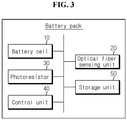
- FIG. 3 is a schematic functional block diagram of a battery pack according to an embodiment of the present disclosure.
- the battery pack includes a battery cell 10, an optical fiber sensing unit 20, a photoresistor 30 and a control unit 40.
- the battery cell 10 is a component that stores and releases electrical energy by repeated charging and discharging, and may be a secondary battery.
- the battery cell 10 according to the present disclosure may be a plate-type battery cell such as a pouch-type secondary battery.
- the battery pack may include at least one battery cell 10.
- the battery pack preferably includes a plurality of battery cells 10.
- the battery cells 10 may be horizontally or vertically stacked and received in a pack case.
- the type or shape of the pack case There is no limitation on the type or shape of the pack case.
- at least one battery cell 10 may be received in the module case to form a battery module, and at least one battery module may be received in the pack case.
- the type or shape of the module case There is no limitation on the type or shape of the module case.
- FIG. 4 is a schematic perspective view of the battery module included in the battery pack according to an embodiment of the present disclosure.
- FIG. 5 is an exploded perspective view of FIG. 4 .
- FIG. 6 is a cross-sectional view taken along the line VI-VI' of FIG. 4 .
- the battery module 100 presented as an example includes a battery cell assembly 110 and a module case 120.
- the battery cell assembly 110 is maintained by the module case 120.
- the module case 120 presented as an example includes a cooling plate 121, a front cover 122, a rear cover 123, side covers 124, 125 and an upper plate 126.
- the battery cell assembly 110 includes at least one battery cell 10.
- the battery cell 10 may include an electrode assembly, an electrolyte solution and a packaging.
- the electrode assembly is an assembly of an electrode and a separator, and may include at least one positive electrode plate and at least one negative electrode plate with the separator interposed between.
- each electrode plate of the electrode assembly has an electrode tab and may be connected to one end of the electrode lead. The other end of the electrode lead is exposed to the outside through the packaging, and the exposed portion may serve as an electrode terminal of the battery cell 10.
- the battery cells 10 may be stacked in at least one direction to form the battery cell assembly 110.
- the plurality of battery cells 10 such as pouch-type secondary batteries may stand upright approximately perpendicular to the ground so that two wide surfaces (large scale areas) are each disposed on the left and right sides, and sealing parts are disposed on the upper, lower, front and rear sides.
- the battery cells 10 standing upright may be arranged in parallel in the left-right directions such that the large scale areas contact each other. That is, the battery cell 10 is a plate-type battery cell and stacks and arranges with another adjacent battery cell such that the large scale areas contact each other to form the battery cell assembly 110.
- the battery cell assembly 110 may be horizontally stacked on the cooling plate 121.
- each battery cell 10 may stand upright on the cooling plate 121, and the bottom of all the battery cells 10 may come into contact with the cooling plate 121. That is, the edge of the battery cell 10 directly cooled by the cooling plate 121 is taken as an example.
- the front cover 122 may be disposed at the front side of the battery cell assembly 110 to cover the front end part of the battery cell assembly 110
- the rear cover 123 may be disposed at the rear side of the battery cell assembly 110 to cover the rear end part of the battery cell assembly 110.
- the electrode lead of each battery cell 10 may extend to the front and rear sides of the battery cell assembly 110
- the front cover 122 and the rear cover 123 may be formed in a concave shape to receive the electrode lead.
- the front cover 122 and the rear cover 123 may be formed in an approximately plate shape with the left and right ends bent approximately at a right angle.
- the front cover 122 and the rear cover 123 may protect the front and rear sides of the battery cell assembly 110 from external physical or chemical factors.
- the side covers 124, 125 may be disposed on the left side and the right side of the battery cell assembly 110 to cover the left surface and right surface of the battery cell assembly 110 respectively.
- the flat surface of the battery cell 10 provided on the outermost side of the battery cell assembly 110 may be disposed, and the side covers 124, 125 may be formed in an approximately plate shape.
- the side covers 124, 125 may be formed in the shape of an approximately rectangular plate as shown in FIG. 4 .
- the side covers 124, 125 may protect the sides of the battery cell assembly 110 from external physical or chemical factors.
- the upper plate 126 may be disposed on the battery cell assembly 110 to cover the top of the battery cell assembly 110.
- the battery cell assembly 110 may be formed in an approximately plate shape.
- the upper plate 126 may be formed in the shape of an approximately rectangular plate as shown in FIGS. 4 and 5 .
- the upper plate 126 may protect the top of the battery cell assembly 110 from external physical or chemical factors.
- the module case 120 includes the cooling plate 121, the front cover 122, the rear cover 123, the side covers 124, 125 and the upper plate 126. They may be coupled by welding or bolting. In another example, the cooling plate 121 may be replaced with a lower plate similar to the upper plate 126.
- the module case 120 may be a monoframe in which the other components than the front cover 122 and the rear cover 123 are connected to form a rectangular tubular shape. The present disclosure is not limited to a particular type or shape of the module case.
- the battery cell assembly 110 of this embodiment does not need a cartridge.
- the cartridge is formed in the shape of an approximately rectangular ring and wraps around the edges of the battery cell 10.
- the cartridge may receive the battery cell 10 in an internal space, and stack the plurality of battery cells 10 such that the plurality of battery cells 10 is arranged side by side.
- the battery pack of the present disclosure may be a battery pack including a cartridge.
- the optical fiber sensing unit 20 which is an important feature of the present disclosure includes a plate-type detection unit 23 made of optical fibers 21 horizontally and vertically arranged in a grid form.
- the plate-type detection unit 23 of the optical fiber sensing unit 20 is deformed by deformation of the battery cell 10.
- the optical fiber sensing unit 20 may be disposed at the large scale area of the battery cell 10.
- the optical fiber sensing unit 20 may be directly attached to the battery cell 10, or may be tightly coupled to a gap between the battery cell 10 and another element.
- the plate-type detection unit 23 of the optical fiber sensing unit 20 preferably has a size and location that covers the large scale area of the battery cell 10.
- the plate-type detection unit 23 is not a sensor in the shape of a point or line nor a sensor disposed locally at only a region of the battery cell 10. Accordingly, it is possible to properly reflect changes of the wide surface of the battery cell 10 made due to swelling.
- the optical fiber 21 assuming a grid form like weft and warp in weaving may be supported by an edge member 22 having an approximately rectangular shape.
- the present disclosure uses light reflection on the surface of the optical fiber 21.
- the present disclosure does not detect a change in intensity of the optical signal that enters one of the ends of the optical fiber 21 and exits the other end. Accordingly, the ends of the optical fiber 21 may be embedded in the edge member 22. There is no need for a light source to generate an optical signal and a detector to detect a change in optical signal intensity. Accordingly, component configuration is very simple.
- the optical fiber 21 includes a core having a high refractive index at the center, and a clad around the core.
- the optical fiber is used to transmit light through the core without light loss by producing the total reflection between the core and the clad.
- the present disclosure allows light to exit the optical fiber 21 through the clad of the optical fiber 21 arranged in a grid form.
- the present disclosure extracts light reflected at the interface between the core and the clad of the optical fiber 21 from the clad and detects the light using the photoresistor as described below.
- the present disclosure proposes the optical fiber sensing unit 20 that causes light to reflect in a region or space that can be measured by the photoresistor and detects the light, and is not a design modification to make the optical fiber grid structure.
- the optical fiber sensing unit 20 may further include a wiring 25 to allow input light or external natural light to enter.
- this embodiment shows the wiring 25 connected to the side of the optical fiber sensing unit 20 in FIG. 5
- the location of the wiring 25 is not limited to the illustrated example.
- the wiring 25 does not need to come into contact with the surface of the battery cell 10.
- the wiring 25 allows light to enter the core of the optical fiber 21, and the incident light reflects and exits the clad of the optical fiber 21 arranged in a grid form.
- the wiring 25 may further include an input light source, and when the control unit includes a light emitting diode (LED) device as described below, light emitted from the LED device may be used as the input light. When light emitted from the LED device is used, the wiring 25 may be connected to the control unit.
- LED light emitting diode
- the optical fiber sensing unit 20 may be disposed in the battery cell assembly 110 or between the battery cell assembly 110 and the module case 120. Accordingly, the optical fiber sensing unit 20 may be disposed between two adjacent battery cells 10 in the battery cell assembly 110. Alternatively, the optical fiber sensing unit 20 may be disposed between the outermost battery cell 10 of the battery cell assembly 110 and the side covers 124, 125. This embodiment shows and describes an example of the optical fiber sensing unit 20 disposed between the battery cell assembly 110 and the right side cover 125. One optical fiber sensing unit 20 may be provided, but at least two optical fiber sensing units 20 may be provided. It is important to provide the plate-type detection unit 23 of the optical fiber sensing unit 20 at a location for covering the large scale area of the battery cell 10.
- the photoresistor 30 collects light reflected from the optical fiber sensing unit 20, and the resistance value changes depending on the amount of the collected light.
- the resistance value may be transmitted to the control unit 40.
- the photoresistor 30 may be attached to the battery cell assembly 110 or the module case 120. This embodiment shows and describes an example in which the photoresistor 30 is attached to the front cover 122 inside the front cover 122, facing the electrode lead.
- the photoresistor 30 may be attached to any location at which light reflected from the optical fiber sensing unit 20 can be collected.
- this embodiment takes an example in which the photoresistor 30 is attached near the upper plate 126 inside the front cover 122, the photoresistor 30 may be disposed closer to the cooling plate 121 inside the front cover 122, may be disposed inside the rear cover 123, may be disposed inside the side covers 124, 125 or may be disposed inside the upper plate 126.
- One photoresistor 30 may be provided, but or at least two photoresistors 30 may be provided.
- the photoresistor is a resistor that changes value with the amount of light.
- the photoresistor may be referred to as a light-dependent resistor (LDR).
- the photoresistor is photoconductive such that electrical resistance is low when the amount of light is large.
- the photoresistor is made of a semiconductor having a high resistance value.
- the resistance value is in mega ohms (M ⁇ ) in the absence of light, and as the amount of light increases, the electrical resistance reduces to a few hundred of ohms.
- M ⁇ mega ohms
- the range of the resistance value and sensitivity vary depending on the type of the semiconductor used. Since the photoresistor works with even a small amount of light, it is very suitable for a usage environment such as the inside of the battery pack
- the control unit 40 may receive the resistance value with a change in the amount of light collected by the photoresistor 30. The control unit 40 may determine if swelling occurred in the battery cell 10 based on the received resistance value.
- FIGS. 5 and 6 show the optical fiber sensing unit 20 before swelling occurs in the battery cell 10.
- the battery cell 10 is deformed, the plate-type detection unit 23 is deformed by the deformation.
- the cross-sectional view of FIG. 7 shows deformation of the optical fiber sensing unit 20 and the battery cell 10 when swollen.
- the large scale area of the battery cell 10 may be deformed in a curved shape.
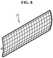
- FIG. 8 is a perspective view of the optical fiber sensing unit 20 in such a condition.
- the plate-type detection unit 23 of the optical fiber sensing unit 20 is deformed by the deformation of the battery cell 10.
- the optical fiber sensing unit 20 When comparing the normal condition of FIG. 6 with the swollen condition of FIG. 7 , deformation of the optical fiber sensing unit 20 is seen. When the optical fiber sensing unit 20 is deformed, the amount of light reflection on the surface of the optical fiber sensing unit 20 changes. Describing in more detail, for example, in the normal condition of FIG. 6 , the optical fiber sensing unit 20 allows light to reflect back to the photoresistor 30 toward the center of the battery cell 10. When the optical fiber sensing unit 20 is deformed as shown in FIG. 7 , the amount of light reflecting back to the photoresistor 30 toward the center of the battery cell 10 changes. The amount of light reduces. In another example, in the normal condition of FIG.
- the optical fiber sensing unit 20 allows light to reflect back through a region that can be measured by the photoresistor 30.
- the amount of reflected light changes.
- the amount of reflected light reduces.
- the photoresistor 30 detects swelling by detecting a difference in the amount of reflected light.
- the control unit 40 determines if swelling occurred in the battery cell based on the resistance value.
- the control unit 40 may inform the condition of the battery pack to a user, or give a notification to provide a solution to the detected condition.
- the photoresistor 30 works with even a small amount of light, it is possible to detect swelling rapidly even when swelling of the battery cell 10 is not severe. Accordingly, it is possible to deal with the swelling of the battery cell 10 at an early stage. Additionally, since light reflection is used, there is no influence of electronic noise. For example, when the battery pack is mounted on a vehicle including an electrical device having a switching device such as an inverter, it is possible to accurately detect a swelling of the battery cell 10.
- the control unit 40 may be configured to give a warning or notify of danger when the change in resistance value is larger than the threshold.
- the threshold may be prestored in memory included in the control unit 40 or a storage device other than the control unit 40.
- the warning or danger notification enables an operation for stopping or dealing with an unsafe condition or providing a notification of an unsafe condition. For example, a variety of actions may be taken to reduce power consumption or shut off the current in order to prevent the explosion of the battery pack or another dangerous situation.
- the control unit 40 may receive the resistance value from the photoresistor 30 at a predetermined time interval, and compare the received current resistance value with the previous resistance value.
- the previous resistance value that is compared with the current resistance value may be a resistance value measured immediately before, and may be a resistance value that was measured at Birth Of Life (BOL) and stored.
- BOL birth Of Life
- the control unit 40 may be configured to interpret the resistance value.
- the threshold may be set as necessary, and when the received current resistance value changes by 30% compared to the resistance value measured at BOL and stored, the control unit 40 may be configured to give a warning, and when the current resistance value changes by 70%, the control unit 40 may be configured to notify of danger. In this case, 30% and 70% are each threshold.
- the control unit 40 may determine that swelling occurred.
- the control unit 40 may give a warning, and when the current resistance value increases by 70% to the resistance value measured at BOL, the control unit 40 may notify of danger.
- the control unit 40 may optionally include processors, application-specific integrated circuits (ASICs), chipsets, logic circuits, registers, communication modems and data processing devices, well known in the art to execute a variety of control logics in the present disclosure. Additionally, when the control logic is implemented in software, the control unit 40 may be implemented as a set of program modules. In this instance, the program module may be stored in memory and executed by the processor. The memory may be inside or outside the processor, and may be connected to the processor with a variety of known means. Further, in many cases, the battery pack includes a control unit, also known as Micro Controller Unit (MCU) or Battery Management System (BMS). The control unit 40 may be implemented by the MCU or the BMS provided in the common battery pack.
- MCU Micro Controller Unit
- BMS Battery Management System
- the battery pack according to an embodiment of the present disclosure may further include a storage unit 50 as shown in FIG. 3 .
- the storage unit 50 may store data or programs required for at least some components of the battery pack according to the present disclosure to perform the operations and functions or data created in the process of performing the operations and functions.
- the storage unit 50 may store programs and data necessary for the control unit 40 to determine if swelling occurred in the battery cell 10.
- the storage unit 50 may store the threshold.
- the storage unit 50 may be a MCU register of the BMS.
- the following is an algorithm working method when the control unit 40 is implemented by the components such as MCU or BMS provided in the common battery pack.
- the initial (or current) amount of reflected light (the resulting resistance value of the photoresistor) is stored in the MCU register of the BMS.
- a control program is set according to the amount of reflected light. For example, when the resistance value of the photoresistor increases by 30%, a warning is set. When the resistance value of the photoresistor increases by 70%, a danger notification is set.
- the amount of reflected light is periodically checked during the use of the battery pack. When the resistance value is reached according to the control program settings, the MCU fault out function of the BMS is performed to provide a notification to the user.
- the present disclosure uses changes in the amount of reflected light with changes in the shape surface of the optical fiber sensing unit 20, converts an analog value of the amount of reflected light to a resistance value through the photoresistor 30, and determines and controls swelling through the resistance value.
- the control unit 40 Since it is not the pressure type detection method, there is no need to place the optical fiber sensing unit 20 at the center of the battery cell 10. Accordingly, it is possible to reduce the volume of the battery pack and improve the energy density of the battery pack.
- external light may come in.
- external light may reach the photoresistor 30 through a gap between the upper plate 126 and the front cover 122. It is possible to detect swelling by a difference in the resistance value of the photoresistor 30 between before and after gap formation.
- the battery pack may include the plurality of battery cells 10 stacked horizontally or vertically and received in the pack case.
- the optical fiber sensing unit and the photoresistor according to the present disclosure may be directly attached to the inside of the pack case.
- the battery pack according to the present disclosure may be applied to a vehicle such as an electric vehicle or a hybrid electric vehicle. That is, the vehicle according to the present disclosure may include the battery pack according to the present disclosure. In addition to the battery pack according to the present disclosure, the vehicle according to the present disclosure may include known components mounted on the vehicle, for example, a driving device such as a motor, an electrical component such as a radio or a navigation, a vehicle body and a controller such as an Electronic Control Unit (ECU).
- ECU Electronic Control Unit
- FIG. 3 shows the control unit 40 included in the battery pack
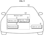
- the control unit 40 may be included in the vehicle outside the battery pack. It will be described in more detail with reference to FIG. 9 .
- FIG. 9 is a schematic diagram of the vehicle according to an embodiment of the present disclosure.
- the vehicle 300 may include a battery pack 200 and a control unit 40.
- the battery pack 200 may include a battery cell 10, an optical fiber sensing unit 20 and a photoresistor 30.
- the control unit 40 may be provided in the vehicle 300, not the battery pack 200.
- the control unit 40 may be implemented by the ECU of the vehicle 300.
- the vehicle according to the present disclosure may further include a storage unit 50.
- the ECU includes a microprocessor such as a Central Processing Unit (CPU), and in addition to the CPU, may include Read Only Memory (ROM) that remembers a processing program, Random Access Memory (RAM) that temporarily remembers data and input/output ports.
- ROM Read Only Memory
- RAM Random Access Memory
- the control unit 40 periodically checks the resistance value of the photoresistor 30.
- the control unit 40 gives a warning when the resistance value of the photoresistor increases by 30%.
- the control unit 40 notifies of danger when the resistance value of the photoresistor increases by 70%.
- each notification may be used to display that the battery pack 200 may have a safety problem to the user, and turn off the device.
- An action taken in response to the notification may be to reduce or remove a situation that triggered the notification.
Landscapes
- Engineering & Computer Science (AREA)
- Chemical & Material Sciences (AREA)
- Chemical Kinetics & Catalysis (AREA)
- Electrochemistry (AREA)
- General Chemical & Material Sciences (AREA)
- Manufacturing & Machinery (AREA)
- Physics & Mathematics (AREA)
- Power Engineering (AREA)
- General Physics & Mathematics (AREA)
- Life Sciences & Earth Sciences (AREA)
- Mechanical Engineering (AREA)
- Transportation (AREA)
- Sustainable Energy (AREA)
- Sustainable Development (AREA)
- Microelectronics & Electronic Packaging (AREA)
- Aviation & Aerospace Engineering (AREA)
- Immunology (AREA)
- Pathology (AREA)
- General Health & Medical Sciences (AREA)
- Biochemistry (AREA)
- Analytical Chemistry (AREA)
- Health & Medical Sciences (AREA)
- Plasma & Fusion (AREA)
- Secondary Cells (AREA)
- Battery Mounting, Suspending (AREA)
Abstract
Description
- The present disclosure relates to battery technology, and more particularly, to technology for detecting swelling of a battery cell more effectively in a battery pack including at least one battery cell. The present application claims the benefit of
Korean Patent Application No. 10-2020-0046096 filed on April 16, 2020 - Currently, commercially available secondary batteries include nickel-cadmium batteries, nickel-hydrogen batteries, nickel-zinc batteries, lithium secondary batteries and the like, and among them, lithium secondary batteries have little or no memory effect, and thus they are gaining more attention than nickel-based secondary batteries for their advantages that recharging can be done whenever it is convenient, the self-discharge rate is very low and the energy density is high.
- To increase the capacity and output of the lithium secondary battery, i.e., the battery, a battery module including an assembly of battery cells connected in series and/or in parallel or a battery pack including at least one battery module is used. The battery module is generally manufactured in the shape shown in
FIG. 1. FIG. 1 shows by example a battery module 4 including abattery cell assembly 1 including a plurality of battery cells arranged and stacked in a direction, and acase 3 having anend plate 2 that covers thebattery cell assembly 1. - One of important considerations of the battery module is safety. In particular, swelling may occur in the lithium secondary battery due to gas generation while in use. The swelling usually occurs in abnormal situations, and when swelling is not detected and the lithium secondary battery is continuously used, a fire or explosion may occur, causing a serious problem.
-
FIG. 2 shows thebattery cell assembly 1 deformed by, for example, swelling occurred in the battery module 4 due to the overcharge of the battery cell. When severe swelling occurs, theend plates 2 at two ends expand and bulge in the outward direction of the battery module 4 as shown inFIG. 2 . Considering the expansion, the battery module may have a margin, but the margin increases the size of the battery module, so the margin is not a proper solution. Alternatively, a stiff end plate may be placed on two sides of the battery cell assembly to suppress an explosion in the battery module, but the forced expansion suppression of the battery module may adversely affect the life (state of health (SOH)) of the battery cell. Accordingly, since it is difficult to manage swelling through structural improvement of the battery module or the case of the battery pack, it is especially important to detect swelling. - Many suggestions have been made to detect swelling so far, but rapid and accurate swelling detection technology is not yet available. In particular, a pressure type detection method by a pressure sensor mainly used to detect swelling has many positional limitations since the pressure sensor should be disposed at the most swollen location, especially, at the center of the battery module. Additionally, the pressure type detection method cannot detect swelling of the battery cell before the battery cell swells so much and the pressure sensor is pressed. Besides, in the case of the pressure type detection method, when the distance between the battery cells is small, even though the battery cell did not swell, the pressure sensor may be pressed, leading to incorrect detection. Accordingly, to prevent this problem, the distance between the battery cells may increase to some extent, but the volume of the battery module increases. When the battery cells are arranged at a smaller interval to reduce the size of the battery module or the battery pack, it is difficult to measure the pressure of each battery cell.
- Accordingly, when swelling is detected more effectively by improving or surpassing the pressure type detection method, it is possible to deal with the swelling before external deformation of the battery module or the battery pack, thereby ensuring safety and reducing customers' complaints.
- The present disclosure is designed to solve the above-described problem, and therefore the present disclosure is directed to providing a battery pack for effectively detecting swelling of a battery cell included in the battery pack and a vehicle comprising the battery pack.
- These and other objects and advantages of the present disclosure may be understood by the following description and will be apparent from the embodiments of the present disclosure. In addition, it will be easily understood that the objects and advantages of the present disclosure may be realized by the means set forth in the appended claims and a combination thereof.
- To achieve the above-described object, a battery pack according to the present disclosure includes at least one battery cell, an optical fiber sensing unit including a plate-type detection unit made of optical fibers horizontally and vertically arranged in a grid form, wherein the plate-type detection unit is deformed by deformation of the battery cell, a photoresistor to collect light reflected from the optical fiber sensing unit, and a control unit configured to determine if swelling occurred in the battery cell based on a resistance value with a change in an amount of light collected by the photoresistor.
- The battery cell may be a plate-type battery cell, and the plate-type detection unit of the optical fiber sensing unit may have a size and location that covers a large scale area of the battery cell.
- The battery cell may be a plate-type battery cell and stacked and arranged with an adjacent battery cell such that the large scale areas come into contact with each other to form a battery cell assembly, the battery cell assembly may be maintained by a case, and the optical fiber sensing unit may be disposed in the battery cell assembly or between the battery cell assembly and the case.
- The photoresistor may be attached to the case. The case may be a module case or a pack case.
- The control unit may be configured to give a warning or notify of danger when a change in the resistance value is larger than a threshold.
- The optical fiber sensing unit may further include a wiring to allow input light or external natural light to enter.
- Additionally, to achieve the above-described object, a vehicle according to an aspect of the present disclosure includes the battery pack according to the present disclosure.
- Additionally, to achieve the above-described object, a vehicle according to another aspect of the present disclosure includes at least one battery cell, an optical fiber sensing unit including a plate-type detection unit made of optical fibers horizontally and vertically arranged in a grid form, wherein the plate-type detection unit is deformed by deformation of the battery cell, a photoresistor to collect light reflected from the optical fiber sensing unit, and a control unit configured to determine if swelling occurred in the battery cell based on a resistance value with a change in an amount of light collected by the photoresistor.
- According to the present disclosure, it is possible to detect swelling of the battery cell provided in the battery pack effectively and accurately.
- Additionally, according to an aspect of the present disclosure, since it is not a pressure type detection method, there is no need for the optical fiber sensing unit at the center of the battery cell, thereby reducing the volume of the battery pack and improving the energy density of the battery pack.
- Additionally, according to an aspect of the present disclosure, even when swelling in the battery cell is not so severe, it is possible to detect the swelling rapidly. Accordingly, according to this aspect of the present disclosure, it is possible to deal with the swelling of the battery cell at the early stage.
- Further, according to an aspect of the present disclosure, it is possible to acquire swelling information of the battery cell in a device including the battery pack, for example, a vehicle including the battery pack.
- The accompanying drawings illustrate a preferred embodiment of the present disclosure, and together with the detailed description of the present disclosure described below, serve to provide a further understanding of the technical aspects of the present disclosure, and thus the present disclosure should not be construed as being limited to the drawings.
-
FIG. 1 is a perspective view showing the shape of a common battery module. -
FIG. 2 is a cross-sectional view taken along the line II-II' ofFIG. 1 , schematically showing an example of swelling occurred in the battery module ofFIG. 1 . -
FIG. 3 is a schematic functional block diagram of a battery pack according to an embodiment of the present disclosure. -
FIG. 4 is a schematic perspective view of a battery module included in a battery pack according to an embodiment of the present disclosure. -
FIG. 5 is an exploded perspective view ofFIG. 4 . -
FIG. 6 is a cross-sectional view taken along the line VI-VI' ofFIG. 4 . -
FIG. 7 is a cross-sectional view showing a battery cell deformed due to swelling and an optical fiber sensing unit deformed due to the battery cell. -
FIG. 8 is a perspective view of an optical fiber sensing unit in the condition ofFIG. 7 . -
FIG. 9 is a schematic diagram of a vehicle according to an embodiment of the present disclosure. - Hereinafter, the preferred embodiments of the present disclosure will be described in detail with reference to the accompanying drawings. Prior to the description, it should be understood that the terms or words used in the specification and the appended claims should not be construed as being limited to general and dictionary meanings, but rather interpreted based on the meanings and concepts corresponding to the technical aspects of the present disclosure on the basis of the principle that the inventor is allowed to define the terms appropriately for the best explanation.
- Therefore, the embodiments described herein and illustrations shown in the drawings are just a most preferred embodiment of the present disclosure, but not intended to fully describe the technical aspects of the present disclosure, so it should be understood that a variety of other equivalents and modifications could have been made thereto at the time that the application was filed.
-
FIG. 3 is a schematic functional block diagram of a battery pack according to an embodiment of the present disclosure. - Referring to
FIG. 3 , the battery pack according to the present disclosure includes abattery cell 10, an opticalfiber sensing unit 20, aphotoresistor 30 and acontrol unit 40. - The
battery cell 10 is a component that stores and releases electrical energy by repeated charging and discharging, and may be a secondary battery. In particular, thebattery cell 10 according to the present disclosure may be a plate-type battery cell such as a pouch-type secondary battery. - Meanwhile, the battery pack may include at least one
battery cell 10. In particular, the battery pack preferably includes a plurality ofbattery cells 10. For example, thebattery cells 10 may be horizontally or vertically stacked and received in a pack case. There is no limitation on the type or shape of the pack case. Alternatively, at least onebattery cell 10 may be received in the module case to form a battery module, and at least one battery module may be received in the pack case. There is no limitation on the type or shape of the module case. -
FIG. 4 is a schematic perspective view of the battery module included in the battery pack according to an embodiment of the present disclosure.FIG. 5 is an exploded perspective view ofFIG. 4 .FIG. 6 is a cross-sectional view taken along the line VI-VI' ofFIG. 4 . - Referring to
FIGS. 4 to 6 , thebattery module 100 presented as an example includes abattery cell assembly 110 and amodule case 120. Thebattery cell assembly 110 is maintained by themodule case 120. Themodule case 120 presented as an example includes acooling plate 121, afront cover 122, arear cover 123, side covers 124, 125 and anupper plate 126. - The
battery cell assembly 110 includes at least onebattery cell 10. Thebattery cell 10 may include an electrode assembly, an electrolyte solution and a packaging. Here, the electrode assembly is an assembly of an electrode and a separator, and may include at least one positive electrode plate and at least one negative electrode plate with the separator interposed between. Additionally, each electrode plate of the electrode assembly has an electrode tab and may be connected to one end of the electrode lead. The other end of the electrode lead is exposed to the outside through the packaging, and the exposed portion may serve as an electrode terminal of thebattery cell 10. - When the
battery module 100 includes a plurality ofbattery cells 10, thebattery cells 10 may be stacked in at least one direction to form thebattery cell assembly 110. For example, as shown inFIG. 5 , the plurality ofbattery cells 10 such as pouch-type secondary batteries may stand upright approximately perpendicular to the ground so that two wide surfaces (large scale areas) are each disposed on the left and right sides, and sealing parts are disposed on the upper, lower, front and rear sides. Thebattery cells 10 standing upright may be arranged in parallel in the left-right directions such that the large scale areas contact each other. That is, thebattery cell 10 is a plate-type battery cell and stacks and arranges with another adjacent battery cell such that the large scale areas contact each other to form thebattery cell assembly 110. - The
battery cell assembly 110 may be horizontally stacked on thecooling plate 121. In this case, eachbattery cell 10 may stand upright on thecooling plate 121, and the bottom of all thebattery cells 10 may come into contact with thecooling plate 121. That is, the edge of thebattery cell 10 directly cooled by thecooling plate 121 is taken as an example. - The
front cover 122 may be disposed at the front side of thebattery cell assembly 110 to cover the front end part of thebattery cell assembly 110, and therear cover 123 may be disposed at the rear side of thebattery cell assembly 110 to cover the rear end part of thebattery cell assembly 110. In particular, the electrode lead of eachbattery cell 10 may extend to the front and rear sides of thebattery cell assembly 110, and thefront cover 122 and therear cover 123 may be formed in a concave shape to receive the electrode lead. For example, thefront cover 122 and therear cover 123 may be formed in an approximately plate shape with the left and right ends bent approximately at a right angle. Thefront cover 122 and therear cover 123 may protect the front and rear sides of thebattery cell assembly 110 from external physical or chemical factors. - The side covers 124, 125 may be disposed on the left side and the right side of the
battery cell assembly 110 to cover the left surface and right surface of thebattery cell assembly 110 respectively. In particular, the flat surface of thebattery cell 10 provided on the outermost side of thebattery cell assembly 110 may be disposed, and the side covers 124, 125 may be formed in an approximately plate shape. For example, the side covers 124, 125 may be formed in the shape of an approximately rectangular plate as shown inFIG. 4 . The side covers 124, 125 may protect the sides of thebattery cell assembly 110 from external physical or chemical factors. - The
upper plate 126 may be disposed on thebattery cell assembly 110 to cover the top of thebattery cell assembly 110. In particular, thebattery cell assembly 110 may be formed in an approximately plate shape. For example, theupper plate 126 may be formed in the shape of an approximately rectangular plate as shown inFIGS. 4 and5 . Theupper plate 126 may protect the top of thebattery cell assembly 110 from external physical or chemical factors. - In this embodiment, the
module case 120 includes thecooling plate 121, thefront cover 122, therear cover 123, the side covers 124, 125 and theupper plate 126. They may be coupled by welding or bolting. In another example, thecooling plate 121 may be replaced with a lower plate similar to theupper plate 126. Themodule case 120 may be a monoframe in which the other components than thefront cover 122 and therear cover 123 are connected to form a rectangular tubular shape. The present disclosure is not limited to a particular type or shape of the module case. - Meanwhile, the
battery cell assembly 110 of this embodiment does not need a cartridge. In general, the cartridge is formed in the shape of an approximately rectangular ring and wraps around the edges of thebattery cell 10. The cartridge may receive thebattery cell 10 in an internal space, and stack the plurality ofbattery cells 10 such that the plurality ofbattery cells 10 is arranged side by side. The battery pack of the present disclosure may be a battery pack including a cartridge. - The optical
fiber sensing unit 20 which is an important feature of the present disclosure includes a plate-type detection unit 23 made ofoptical fibers 21 horizontally and vertically arranged in a grid form. The plate-type detection unit 23 of the opticalfiber sensing unit 20 is deformed by deformation of thebattery cell 10. To this end, the opticalfiber sensing unit 20 may be disposed at the large scale area of thebattery cell 10. The opticalfiber sensing unit 20 may be directly attached to thebattery cell 10, or may be tightly coupled to a gap between thebattery cell 10 and another element. - The plate-
type detection unit 23 of the opticalfiber sensing unit 20 preferably has a size and location that covers the large scale area of thebattery cell 10. The plate-type detection unit 23 is not a sensor in the shape of a point or line nor a sensor disposed locally at only a region of thebattery cell 10. Accordingly, it is possible to properly reflect changes of the wide surface of thebattery cell 10 made due to swelling. - The
optical fiber 21 assuming a grid form like weft and warp in weaving may be supported by anedge member 22 having an approximately rectangular shape. As opposed to a general usage example of an optical fiber having an input terminal and an output terminal at two ends for signal transmission in which an optical signal enters the input terminal, the present disclosure uses light reflection on the surface of theoptical fiber 21. The present disclosure does not detect a change in intensity of the optical signal that enters one of the ends of theoptical fiber 21 and exits the other end. Accordingly, the ends of theoptical fiber 21 may be embedded in theedge member 22. There is no need for a light source to generate an optical signal and a detector to detect a change in optical signal intensity. Accordingly, component configuration is very simple. - As well known, the
optical fiber 21 includes a core having a high refractive index at the center, and a clad around the core. Conventionally, the optical fiber is used to transmit light through the core without light loss by producing the total reflection between the core and the clad. As opposed to the conventional art, the present disclosure allows light to exit theoptical fiber 21 through the clad of theoptical fiber 21 arranged in a grid form. The present disclosure extracts light reflected at the interface between the core and the clad of theoptical fiber 21 from the clad and detects the light using the photoresistor as described below. The present disclosure proposes the opticalfiber sensing unit 20 that causes light to reflect in a region or space that can be measured by the photoresistor and detects the light, and is not a design modification to make the optical fiber grid structure. - Meanwhile, the optical
fiber sensing unit 20 may further include awiring 25 to allow input light or external natural light to enter. Although this embodiment shows thewiring 25 connected to the side of the opticalfiber sensing unit 20 inFIG. 5 , the location of thewiring 25 is not limited to the illustrated example. Thewiring 25 does not need to come into contact with the surface of thebattery cell 10. Thewiring 25 allows light to enter the core of theoptical fiber 21, and the incident light reflects and exits the clad of theoptical fiber 21 arranged in a grid form. Thewiring 25 may further include an input light source, and when the control unit includes a light emitting diode (LED) device as described below, light emitted from the LED device may be used as the input light. When light emitted from the LED device is used, thewiring 25 may be connected to the control unit. - The optical
fiber sensing unit 20 may be disposed in thebattery cell assembly 110 or between thebattery cell assembly 110 and themodule case 120. Accordingly, the opticalfiber sensing unit 20 may be disposed between twoadjacent battery cells 10 in thebattery cell assembly 110. Alternatively, the opticalfiber sensing unit 20 may be disposed between theoutermost battery cell 10 of thebattery cell assembly 110 and the side covers 124, 125. This embodiment shows and describes an example of the opticalfiber sensing unit 20 disposed between thebattery cell assembly 110 and theright side cover 125. One opticalfiber sensing unit 20 may be provided, but at least two opticalfiber sensing units 20 may be provided. It is important to provide the plate-type detection unit 23 of the opticalfiber sensing unit 20 at a location for covering the large scale area of thebattery cell 10. - The
photoresistor 30 collects light reflected from the opticalfiber sensing unit 20, and the resistance value changes depending on the amount of the collected light. The resistance value may be transmitted to thecontrol unit 40. Thephotoresistor 30 may be attached to thebattery cell assembly 110 or themodule case 120. This embodiment shows and describes an example in which thephotoresistor 30 is attached to thefront cover 122 inside thefront cover 122, facing the electrode lead. Thephotoresistor 30 may be attached to any location at which light reflected from the opticalfiber sensing unit 20 can be collected. For example, although this embodiment takes an example in which thephotoresistor 30 is attached near theupper plate 126 inside thefront cover 122, thephotoresistor 30 may be disposed closer to thecooling plate 121 inside thefront cover 122, may be disposed inside therear cover 123, may be disposed inside the side covers 124, 125 or may be disposed inside theupper plate 126. Onephotoresistor 30 may be provided, but or at least twophotoresistors 30 may be provided. - The photoresistor is a resistor that changes value with the amount of light. The photoresistor may be referred to as a light-dependent resistor (LDR). The photoresistor is photoconductive such that electrical resistance is low when the amount of light is large. The photoresistor is made of a semiconductor having a high resistance value. The resistance value is in mega ohms (MΩ) in the absence of light, and as the amount of light increases, the electrical resistance reduces to a few hundred of ohms. When light having a particular frequency in the operating range is transmitted to the semiconductor, electrons are released and the resistor reaches the conduction band. Accordingly, free electrons and holes are formed and the resistance value reduces. The range of the resistance value and sensitivity vary depending on the type of the semiconductor used. Since the photoresistor works with even a small amount of light, it is very suitable for a usage environment such as the inside of the battery pack.
- The
control unit 40 may receive the resistance value with a change in the amount of light collected by thephotoresistor 30. Thecontrol unit 40 may determine if swelling occurred in thebattery cell 10 based on the received resistance value. -
FIGS. 5 and6 show the opticalfiber sensing unit 20 before swelling occurs in thebattery cell 10. When swelling occurs in thebattery cell 10, thebattery cell 10 is deformed, the plate-type detection unit 23 is deformed by the deformation. For example, when comparing with the opticalfiber sensing unit 20 attached to thebattery cell 10 in normal condition as shown in the cross-sectional view ofFIG. 6 , the cross-sectional view ofFIG. 7 shows deformation of the opticalfiber sensing unit 20 and thebattery cell 10 when swollen. When thebattery cell 10 swells, the large scale area of thebattery cell 10 may be deformed in a curved shape.FIG. 8 is a perspective view of the opticalfiber sensing unit 20 in such a condition. The plate-type detection unit 23 of the opticalfiber sensing unit 20 is deformed by the deformation of thebattery cell 10. - When comparing the normal condition of
FIG. 6 with the swollen condition ofFIG. 7 , deformation of the opticalfiber sensing unit 20 is seen. When the opticalfiber sensing unit 20 is deformed, the amount of light reflection on the surface of the opticalfiber sensing unit 20 changes. Describing in more detail, for example, in the normal condition ofFIG. 6 , the opticalfiber sensing unit 20 allows light to reflect back to thephotoresistor 30 toward the center of thebattery cell 10. When the opticalfiber sensing unit 20 is deformed as shown inFIG. 7 , the amount of light reflecting back to thephotoresistor 30 toward the center of thebattery cell 10 changes. The amount of light reduces. In another example, in the normal condition ofFIG. 6 , the opticalfiber sensing unit 20 allows light to reflect back through a region that can be measured by thephotoresistor 30. When the opticalfiber sensing unit 20 is deformed as shown inFIG. 7 , the amount of reflected light changes. The amount of reflected light reduces. Thephotoresistor 30 detects swelling by detecting a difference in the amount of reflected light. - There is a difference in the amount of reflected light reaching the
photoresistor 30 between the normal condition and the swollen condition. Accordingly, the resistance value of the photoresistor 30 changes, and when thecontrol unit 40 receives the resistance value, thecontrol unit 40 determines if swelling occurred in the battery cell based on the resistance value. When swelling is detected, thecontrol unit 40 may inform the condition of the battery pack to a user, or give a notification to provide a solution to the detected condition. - Since the
photoresistor 30 works with even a small amount of light, it is possible to detect swelling rapidly even when swelling of thebattery cell 10 is not severe. Accordingly, it is possible to deal with the swelling of thebattery cell 10 at an early stage. Additionally, since light reflection is used, there is no influence of electronic noise. For example, when the battery pack is mounted on a vehicle including an electrical device having a switching device such as an inverter, it is possible to accurately detect a swelling of thebattery cell 10. - The
control unit 40 may be configured to give a warning or notify of danger when the change in resistance value is larger than the threshold. The threshold may be prestored in memory included in thecontrol unit 40 or a storage device other than thecontrol unit 40. The warning or danger notification enables an operation for stopping or dealing with an unsafe condition or providing a notification of an unsafe condition. For example, a variety of actions may be taken to reduce power consumption or shut off the current in order to prevent the explosion of the battery pack or another dangerous situation. - The
control unit 40 may receive the resistance value from thephotoresistor 30 at a predetermined time interval, and compare the received current resistance value with the previous resistance value. The previous resistance value that is compared with the current resistance value may be a resistance value measured immediately before, and may be a resistance value that was measured at Birth Of Life (BOL) and stored. Thecontrol unit 40 may be configured to interpret the resistance value. - The threshold may be set as necessary, and when the received current resistance value changes by 30% compared to the resistance value measured at BOL and stored, the
control unit 40 may be configured to give a warning, and when the current resistance value changes by 70%, thecontrol unit 40 may be configured to notify of danger. In this case, 30% and 70% are each threshold. - When the optical
fiber sensing unit 20 is deformed, the amount of reflected light reaching thephotoresistor 30 reduces. Accordingly, the resistance value of thephotoresistor 30 increases. Accordingly, when thecontrol unit 40 detects an increase in resistance value, thecontrol unit 40 may determine that swelling occurred. When the received current resistance value increases by 30% compared to the resistance value measured at BOL, thecontrol unit 40 may give a warning, and when the current resistance value increases by 70% to the resistance value measured at BOL, thecontrol unit 40 may notify of danger. - The
control unit 40 may optionally include processors, application-specific integrated circuits (ASICs), chipsets, logic circuits, registers, communication modems and data processing devices, well known in the art to execute a variety of control logics in the present disclosure. Additionally, when the control logic is implemented in software, thecontrol unit 40 may be implemented as a set of program modules. In this instance, the program module may be stored in memory and executed by the processor. The memory may be inside or outside the processor, and may be connected to the processor with a variety of known means. Further, in many cases, the battery pack includes a control unit, also known as Micro Controller Unit (MCU) or Battery Management System (BMS). Thecontrol unit 40 may be implemented by the MCU or the BMS provided in the common battery pack. - Meanwhile, the battery pack according to an embodiment of the present disclosure may further include a
storage unit 50 as shown inFIG. 3 . Thestorage unit 50 may store data or programs required for at least some components of the battery pack according to the present disclosure to perform the operations and functions or data created in the process of performing the operations and functions. In particular, thestorage unit 50 may store programs and data necessary for thecontrol unit 40 to determine if swelling occurred in thebattery cell 10. For example, thestorage unit 50 may store the threshold. Thestorage unit 50 may be a MCU register of the BMS. - The following is an algorithm working method when the
control unit 40 is implemented by the components such as MCU or BMS provided in the common battery pack. The initial (or current) amount of reflected light (the resulting resistance value of the photoresistor) is stored in the MCU register of the BMS. A control program is set according to the amount of reflected light. For example, when the resistance value of the photoresistor increases by 30%, a warning is set. When the resistance value of the photoresistor increases by 70%, a danger notification is set. The amount of reflected light is periodically checked during the use of the battery pack. When the resistance value is reached according to the control program settings, the MCU fault out function of the BMS is performed to provide a notification to the user. - The present disclosure uses changes in the amount of reflected light with changes in the shape surface of the optical
fiber sensing unit 20, converts an analog value of the amount of reflected light to a resistance value through thephotoresistor 30, and determines and controls swelling through the resistance value. In other words, when thebattery cell 10 swells, the surface of the opticalfiber sensing unit 20 in a grid form is deformed, light reflection on the opticalfiber sensing unit 20 changes, and accordingly, the resistance value of the photoresistor 30 changes, and the change is detected by thecontrol unit 40. Since it is not the pressure type detection method, there is no need to place the opticalfiber sensing unit 20 at the center of thebattery cell 10. Accordingly, it is possible to reduce the volume of the battery pack and improve the energy density of the battery pack. - Meanwhile, when the components of the
module case 120 bend due to excessive swelling to form a gap between the components, external light may come in. For example, external light may reach thephotoresistor 30 through a gap between theupper plate 126 and thefront cover 122. It is possible to detect swelling by a difference in the resistance value of thephotoresistor 30 between before and after gap formation. - Although the case in which the battery pack includes the battery module and the battery module includes the
battery cell 10 is described with reference toFIGS. 4 to 6 , the battery pack may include the plurality ofbattery cells 10 stacked horizontally or vertically and received in the pack case. In this case, the optical fiber sensing unit and the photoresistor according to the present disclosure may be directly attached to the inside of the pack case. - The battery pack according to the present disclosure may be applied to a vehicle such as an electric vehicle or a hybrid electric vehicle. That is, the vehicle according to the present disclosure may include the battery pack according to the present disclosure. In addition to the battery pack according to the present disclosure, the vehicle according to the present disclosure may include known components mounted on the vehicle, for example, a driving device such as a motor, an electrical component such as a radio or a navigation, a vehicle body and a controller such as an Electronic Control Unit (ECU).
- Meanwhile, some of the components of the battery pack according to the present disclosure may be provided in the vehicle. In particular, although the embodiment of
FIG. 3 shows thecontrol unit 40 included in the battery pack, thecontrol unit 40 may be included in the vehicle outside the battery pack. It will be described in more detail with reference toFIG. 9 . -
FIG. 9 is a schematic diagram of the vehicle according to an embodiment of the present disclosure. - Referring to
FIG. 9 , thevehicle 300 according to the present disclosure may include abattery pack 200 and acontrol unit 40. Additionally, thebattery pack 200 may include abattery cell 10, an opticalfiber sensing unit 20 and aphotoresistor 30. In particular, as shown inFIG. 9 , thecontrol unit 40 may be provided in thevehicle 300, not thebattery pack 200. For example, thecontrol unit 40 may be implemented by the ECU of thevehicle 300. - In the case of the embodiment of
FIG. 9 , except that thecontrol unit 40 is provided in thevehicle 300, not thebattery pack 200, the description of the previous embodiment may be equally or similarly applied. Accordingly, to avoid redundancy, the repeated detailed description of each component of thebattery cell 10, the opticalfiber sensing unit 20, thephotoresistor 30 and thecontrol unit 40 is omitted herein. Additionally, although not shown inFIG. 9 , the vehicle according to the present disclosure may further include astorage unit 50. - The ECU includes a microprocessor such as a Central Processing Unit (CPU), and in addition to the CPU, may include Read Only Memory (ROM) that remembers a processing program, Random Access Memory (RAM) that temporarily remembers data and input/output ports. Accordingly, when the
control unit 40 is implemented by the ECU of thevehicle 300, thestorage unit 50 may be ROM and RAM - The
control unit 40 periodically checks the resistance value of thephotoresistor 30. Thecontrol unit 40 gives a warning when the resistance value of the photoresistor increases by 30%. Thecontrol unit 40 notifies of danger when the resistance value of the photoresistor increases by 70%. For example, each notification may be used to display that thebattery pack 200 may have a safety problem to the user, and turn off the device. An action taken in response to the notification may be to reduce or remove a situation that triggered the notification. - As described above, it is possible to acquire the swelling information of the battery cell in the device including the battery pack according to the present disclosure, for example, the vehicle including the battery pack.
- Meanwhile, the terms indicating directions such as upper, lower, left, right, front and rear are used herein for convenience of description only, and it is obvious to those skilled in the art that the term may change depending on the position of the stated elements or an observer.
- While the present disclosure has been hereinabove described with regard to a limited number of embodiments and drawings, the present disclosure is not limited thereto, and it is obvious to those skilled in the art that a variety of modifications and changes may be made thereto within the technical aspects of the present disclosure and the equivalent scope of the appended claims.
Claims (9)
- A battery pack, comprising:at least one battery cell;an optical fiber sensing unit including a plate-type detection unit made of optical fibers horizontally and vertically arranged in a grid form, wherein the plate-type detection unit is deformed by deformation of the battery cell;a photoresistor to collect light reflected from the optical fiber sensing unit; anda control unit configured to determine if swelling occurred in the battery cell based on a resistance value with a change in an amount of light collected by the photoresistor.
- The battery pack according to claim 1, wherein the battery cell is a plate-type battery cell, and the plate-type detection unit of the optical fiber sensing unit has a size and location that covers a large scale area of the battery cell.
- The battery pack according to claim 2, wherein the battery cell is a plate-type battery cell and stacked and arranged with an adjacent battery cell such that the large scale areas come into contact with each other to form a battery cell assembly, the battery cell assembly is maintained by a case, and the optical fiber sensing unit is disposed in the battery cell assembly or between the battery cell assembly and the case.
- The battery pack according to claim 3, wherein the photoresistor is attached to the case.
- The battery pack according to claim 1, wherein the control unit is configured to give a warning or notify of danger when a change in the resistance value is larger than a threshold.
- The battery pack according to claim 1, wherein the optical fiber sensing unit further comprises a wiring to allow input light or external natural light to enter.
- A vehicle comprising the battery pack according to any one of claims 1 to 6.
- A vehicle, comprising:at least one battery cell;an optical fiber sensing unit including a plate-type detection unit made of optical fibers horizontally and vertically arranged in a grid form, wherein the plate-type detection unit is deformed by deformation of the battery cell;a photoresistor to collect light reflected from the optical fiber sensing unit; anda control unit configured to determine if swelling occurred in the battery cell based on a resistance value with a change in an amount of light collected by the photoresistor.
- The vehicle according to claim 8, wherein the control unit is configured to give a warning or notify of danger when a change in the resistance value is larger than a threshold.
Applications Claiming Priority (2)
| Application Number | Priority Date | Filing Date | Title |
|---|---|---|---|
| KR1020200046096A KR102846100B1 (en) | 2020-04-16 | 2020-04-16 | Battery Pack for swelling detection |
| PCT/KR2020/015342 WO2021210745A1 (en) | 2020-04-16 | 2020-11-04 | Battery pack capable of sensing swelling |
Publications (2)
| Publication Number | Publication Date |
|---|---|
| EP3968436A1 true EP3968436A1 (en) | 2022-03-16 |
| EP3968436A4 EP3968436A4 (en) | 2022-11-09 |
Family
ID=78084003
Family Applications (1)
| Application Number | Title | Priority Date | Filing Date |
|---|---|---|---|
| EP20931467.3A Pending EP3968436A4 (en) | 2020-04-16 | 2020-11-04 | BATTERY PACK THAT CAN DETECT SWELLING |
Country Status (6)
| Country | Link |
|---|---|
| US (1) | US12002935B2 (en) |
| EP (1) | EP3968436A4 (en) |
| JP (1) | JP7237156B2 (en) |
| KR (1) | KR102846100B1 (en) |
| CN (1) | CN113826264B (en) |
| WO (1) | WO2021210745A1 (en) |
Cited By (1)
| Publication number | Priority date | Publication date | Assignee | Title |
|---|---|---|---|---|
| WO2025006136A1 (en) * | 2023-06-30 | 2025-01-02 | Apple Inc. | Smart enclosures for batteries in consumer electronics |
Families Citing this family (6)
| Publication number | Priority date | Publication date | Assignee | Title |
|---|---|---|---|---|
| US11443569B1 (en) * | 2021-10-30 | 2022-09-13 | Beta Air, Llc | Systems and methods for battery management for a vehicle |
| US20230155188A1 (en) * | 2021-11-18 | 2023-05-18 | Hilti Aktiengesellschaft | Damage detector for a rechargeable battery |
| EP4266449A1 (en) * | 2022-04-19 | 2023-10-25 | Abb Schweiz Ag | Battery arrangement and method for estimating at least one property of a battery cell of a battery arrangement |
| CN115112036B (en) * | 2022-06-28 | 2023-04-07 | 上海拜安传感技术有限公司 | Monitoring system of battery module |
| JP2026508112A (en) * | 2023-01-30 | 2026-03-10 | ジェイティー インターナショナル エスエイ | Battery Module System |
| JP7827004B2 (en) * | 2023-04-28 | 2026-03-10 | トヨタ自動車株式会社 | Battery system and method for detecting abnormalities in battery system |
Family Cites Families (25)
| Publication number | Priority date | Publication date | Assignee | Title |
|---|---|---|---|---|
| JP3829180B2 (en) * | 2002-02-08 | 2006-10-04 | 飛島建設株式会社 | Ground deformation measurement system using optical fiber sensor |
| JP3983139B2 (en) * | 2002-08-30 | 2007-09-26 | 三洋電機株式会社 | Power supply for vehicle |
| JP2005018417A (en) * | 2003-06-26 | 2005-01-20 | Sony Corp | Monitoring device and monitoring method |
| JP2009059582A (en) | 2007-08-31 | 2009-03-19 | Toyota Motor Corp | Secondary battery pressure detector |
| KR100943166B1 (en) * | 2008-03-31 | 2010-02-19 | 한국시설안전공단 | Optical fiber displacement meter and slope safety monitoring system |
| JP4580037B1 (en) * | 2010-03-29 | 2010-11-10 | エンパイア テクノロジー ディベロップメント エルエルシー | Battery system and battery safety alarm system |
| JP4580038B1 (en) | 2010-04-27 | 2010-11-10 | エンパイア テクノロジー ディベロップメント エルエルシー | Battery system and battery safety alarm system |
| WO2012057787A1 (en) | 2010-10-29 | 2012-05-03 | Empire Technology Development Llc | Energy storage apparatus |
| JP2013145716A (en) | 2012-01-16 | 2013-07-25 | Toyota Industries Corp | Battery module and vehicle |
| KR101721046B1 (en) | 2012-04-08 | 2017-03-29 | 삼성전자주식회사 | Display appartus and display appartus controlling method |
| US10211489B2 (en) * | 2012-08-10 | 2019-02-19 | Battelle Memorial Institute | Integral light sources and detectors for an optical sensor to detect battery faults |
| JP5881593B2 (en) | 2012-12-17 | 2016-03-09 | 三菱重工業株式会社 | Battery system, battery monitoring apparatus and battery monitoring method |
| JP2017026311A (en) * | 2013-12-02 | 2017-02-02 | コニカミノルタ株式会社 | Signal amplification device and sensor device |
| DE102014219720B4 (en) * | 2014-09-29 | 2020-07-30 | Fraunhofer-Gesellschaft zur Förderung der angewandten Forschung e.V. | Battery and method of operating it |
| KR101615043B1 (en) * | 2014-12-03 | 2016-04-29 | 한국광기술원 | System for monitering integrity of guide rail |
| EP3104447B1 (en) * | 2015-06-09 | 2019-04-24 | Volvo Car Corporation | Damage detection & warning system of a battery pack |
| KR101950463B1 (en) * | 2015-10-06 | 2019-02-20 | 주식회사 엘지화학 | Battery Module Having Prove for Sensing Expansion of Battery Cell |
| US20170131357A1 (en) * | 2015-11-09 | 2017-05-11 | Patricia NIEVA | Method and apparatus for monitoring and determining energy storage device characteristics using fiber optics |
| KR101872901B1 (en) | 2016-11-03 | 2018-07-02 | (주) 지에스씨 솔루션 | Lithium ion battery having safety device |
| CN206340633U (en) * | 2016-12-28 | 2017-07-18 | 谢建毫 | A kind of automobile batteries device for detecting temperature |
| EP3683522B1 (en) | 2017-09-11 | 2022-10-26 | Zhejiang Sanhua Intelligent Controls Co., Ltd. | Fluid control assembly |
| CN208013385U (en) * | 2017-10-24 | 2018-10-26 | 东莞市安德丰电池有限公司 | A photoelectric detection device for lithium battery bulging |
| KR102447552B1 (en) | 2018-03-09 | 2022-09-23 | 주식회사 엘지에너지솔루션 | Secondary battery state detection device |
| US11585861B2 (en) * | 2018-05-07 | 2023-02-21 | Joby Aero, Inc. | Vehicle battery pack health monitoring |
| CN208284596U (en) | 2018-07-03 | 2018-12-25 | 华霆(合肥)动力技术有限公司 | Battery modules, power supply device and cell safety detection device |
-
2020
- 2020-04-16 KR KR1020200046096A patent/KR102846100B1/en active Active
- 2020-11-04 JP JP2021528433A patent/JP7237156B2/en active Active
- 2020-11-04 CN CN202080032684.7A patent/CN113826264B/en active Active
- 2020-11-04 EP EP20931467.3A patent/EP3968436A4/en active Pending
- 2020-11-04 WO PCT/KR2020/015342 patent/WO2021210745A1/en not_active Ceased
-
2021
- 2021-10-15 US US17/503,083 patent/US12002935B2/en active Active
Cited By (1)
| Publication number | Priority date | Publication date | Assignee | Title |
|---|---|---|---|---|
| WO2025006136A1 (en) * | 2023-06-30 | 2025-01-02 | Apple Inc. | Smart enclosures for batteries in consumer electronics |
Also Published As
| Publication number | Publication date |
|---|---|
| US20220037708A1 (en) | 2022-02-03 |
| KR20210128196A (en) | 2021-10-26 |
| EP3968436A4 (en) | 2022-11-09 |
| KR102846100B1 (en) | 2025-08-12 |
| JP7237156B2 (en) | 2023-03-10 |
| US12002935B2 (en) | 2024-06-04 |
| WO2021210745A1 (en) | 2021-10-21 |
| CN113826264A (en) | 2021-12-21 |
| CN113826264B (en) | 2024-07-12 |
| JP2022532459A (en) | 2022-07-15 |
Similar Documents
| Publication | Publication Date | Title |
|---|---|---|
| US12002935B2 (en) | Battery pack capable of swelling detection | |
| ES3014385T3 (en) | Battery module and battery pack comprising battery module | |
| JP5976108B2 (en) | Battery pack with improved safety | |
| TWI734880B (en) | Bettery cell and bettery pack | |
| KR102949544B1 (en) | Battery Pack with improved accuracy of swelling measurement | |
| KR102884362B1 (en) | Battery module | |
| KR20090131573A (en) | Power cut-off device when overcharging battery | |
| CN117117355B (en) | Liquid leakage detection device and battery | |
| ES3038097T3 (en) | Battery module having fire extinguishing unit | |
| JP2023505981A (en) | Pouch type battery with swelling sensor | |
| US11598814B2 (en) | Battery management apparatus and method | |
| EP4283758A1 (en) | Battery module with pressure sensor for thermal runaway detection | |
| JP2010165585A (en) | Power storage device | |
| KR20220056445A (en) | Battery Pack Comprising Sensor Member | |
| EP4432446B1 (en) | Battery module, and battery pack and vehicle including the same | |
| KR102933965B1 (en) | Battery module and battery managing system incluting the same | |
| KR20220048344A (en) | Battery Module, Battery Pack, and Electric Vehicle | |
| CN223911689U (en) | Battery device and electric equipment | |
| CN220821791U (en) | Module frame and battery module | |
| EP4485618A1 (en) | Flexible printed circuit board and secondary battery module comprising same | |
| JP2019102222A (en) | Battery pack and housing body | |
| KR102870261B1 (en) | Cylindrical type secondary battery module | |
| CN109606117A (en) | Contactor control system and method for battery management system | |
| KR20250021988A (en) | Battery system and method for determination of a thermal runaway | |
| KR20260045447A (en) | Battery module and battery temperature management system |
Legal Events
| Date | Code | Title | Description |
|---|---|---|---|
| STAA | Information on the status of an ep patent application or granted ep patent |
Free format text: STATUS: THE INTERNATIONAL PUBLICATION HAS BEEN MADE |
|
| PUAI | Public reference made under article 153(3) epc to a published international application that has entered the european phase |
Free format text: ORIGINAL CODE: 0009012 |
|
| STAA | Information on the status of an ep patent application or granted ep patent |
Free format text: STATUS: REQUEST FOR EXAMINATION WAS MADE |
|
| 17P | Request for examination filed |
Effective date: 20211207 |
|
| AK | Designated contracting states |
Kind code of ref document: A1 Designated state(s): AL AT BE BG CH CY CZ DE DK EE ES FI FR GB GR HR HU IE IS IT LI LT LU LV MC MK MT NL NO PL PT RO RS SE SI SK SM TR |
|
| RAP3 | Party data changed (applicant data changed or rights of an application transferred) |
Owner name: LG ENERGY SOLUTION, LTD. |
|
| A4 | Supplementary search report drawn up and despatched |
Effective date: 20221012 |
|
| RIC1 | Information provided on ipc code assigned before grant |
Ipc: H01M 50/258 20210101ALI20221006BHEP Ipc: H01M 50/249 20210101ALI20221006BHEP Ipc: H01M 50/242 20210101ALI20221006BHEP Ipc: H01M 50/211 20210101ALI20221006BHEP Ipc: G01B 7/16 20060101ALI20221006BHEP Ipc: B60L 50/64 20190101ALI20221006BHEP Ipc: B60L 3/00 20190101ALI20221006BHEP Ipc: G01B 11/16 20060101ALI20221006BHEP Ipc: H01M 10/42 20060101ALI20221006BHEP Ipc: H01M 10/48 20060101AFI20221006BHEP |
|
| DAV | Request for validation of the european patent (deleted) | ||
| DAX | Request for extension of the european patent (deleted) |