EP3968348A1 - Switch for use in switching signals and apparatus for transmitting or receiving rf signals - Google Patents
Switch for use in switching signals and apparatus for transmitting or receiving rf signals Download PDFInfo
- Publication number
- EP3968348A1 EP3968348A1 EP20196036.6A EP20196036A EP3968348A1 EP 3968348 A1 EP3968348 A1 EP 3968348A1 EP 20196036 A EP20196036 A EP 20196036A EP 3968348 A1 EP3968348 A1 EP 3968348A1
- Authority
- EP
- European Patent Office
- Prior art keywords
- fluid
- switch
- fluid reservoir
- electrical contacts
- reservoir
- Prior art date
- Legal status (The legal status is an assumption and is not a legal conclusion. Google has not performed a legal analysis and makes no representation as to the accuracy of the status listed.)
- Withdrawn
Links
Images


Classifications
-
- H—ELECTRICITY
- H01—ELECTRIC ELEMENTS
- H01H—ELECTRIC SWITCHES; RELAYS; SELECTORS; EMERGENCY PROTECTIVE DEVICES
- H01H3/00—Mechanisms for operating contacts
- H01H3/22—Power arrangements internal to the switch for operating the driving mechanism
- H01H3/24—Power arrangements internal to the switch for operating the driving mechanism using pneumatic or hydraulic actuator
-
- H—ELECTRICITY
- H01—ELECTRIC ELEMENTS
- H01H—ELECTRIC SWITCHES; RELAYS; SELECTORS; EMERGENCY PROTECTIVE DEVICES
- H01H35/00—Switches operated by change of a physical condition
- H01H35/24—Switches operated by change of fluid pressure, by fluid pressure waves, or by change of fluid flow
- H01H35/34—Switches operated by change of fluid pressure, by fluid pressure waves, or by change of fluid flow actuated by diaphragm
-
- F—MECHANICAL ENGINEERING; LIGHTING; HEATING; WEAPONS; BLASTING
- F15—FLUID-PRESSURE ACTUATORS; HYDRAULICS OR PNEUMATICS IN GENERAL
- F15B—SYSTEMS ACTING BY MEANS OF FLUIDS IN GENERAL; FLUID-PRESSURE ACTUATORS, e.g. SERVOMOTORS; DETAILS OF FLUID-PRESSURE SYSTEMS, NOT OTHERWISE PROVIDED FOR
- F15B15/00—Fluid-actuated devices for displacing a member from one position to another; Gearing associated therewith
- F15B15/08—Characterised by the construction of the motor unit
- F15B15/10—Characterised by the construction of the motor unit the motor being of diaphragm type
-
- H—ELECTRICITY
- H01—ELECTRIC ELEMENTS
- H01H—ELECTRIC SWITCHES; RELAYS; SELECTORS; EMERGENCY PROTECTIVE DEVICES
- H01H29/00—Switches having at least one liquid contact
- H01H29/004—Operated by deformation of container
-
- H—ELECTRICITY
- H01—ELECTRIC ELEMENTS
- H01H—ELECTRIC SWITCHES; RELAYS; SELECTORS; EMERGENCY PROTECTIVE DEVICES
- H01H3/00—Mechanisms for operating contacts
- H01H3/02—Operating parts, i.e. for operating driving mechanism by a mechanical force external to the switch
- H01H3/0206—Combined operation of electric switch and of fluid control device
-
- H—ELECTRICITY
- H01—ELECTRIC ELEMENTS
- H01H—ELECTRIC SWITCHES; RELAYS; SELECTORS; EMERGENCY PROTECTIVE DEVICES
- H01H35/00—Switches operated by change of a physical condition
- H01H35/24—Switches operated by change of fluid pressure, by fluid pressure waves, or by change of fluid flow
- H01H35/245—Switches operated by change of fluid pressure, by fluid pressure waves, or by change of fluid flow actuated by the deformation of a body of elastic material
Definitions
- a switch for use in switching signals in an apparatus the switch being a fluid-mechanical circuit switch and comprising:
- the fluid lines may be for example discrete pipes or may be in the form of channels formed in a substrate.
- apparatus for transmitting RF signals or receiving RF signals or transmitting and receiving RF signals comprising:
- the apparatus comprises a pump for pumping fluid into the fluid reservoir.
- switches are often used in RF (radio frequency) and other switching applications, for example to switch two circuits between a single antenna or to switch one or more circuits between two (or more) antennas.
- PIN diodes are used in such RF applications, including for example in MIMO (multiple-input and multiple-output) techniques which use multiple antennas or to switch an antenna between transmit and receive circuits as necessary.
- MIMO multiple-input and multiple-output
- PIN diodes are relatively expensive.
- additional circuitry is required in order to drive operation of the PIN diodes.
- FETs field effect transistors
- MEMs micro-electromechanical systems
- a switch for use in switching signals in an apparatus.
- the switch is a fluid-mechanical circuit switch. That is, the switch is in essence a mechanical switch that is operated using a fluid, and specifically in examples by fluid pressure. This contrasts for example with the electronic or electromechanical switches used or proposed for use in the prior art.
- the switch has a fluid reservoir and (at least) two electrical contacts.
- the fluid reservoir expands and contracts as fluid is introduced into and removed from the fluid reservoir respectively.
- the electrical contacts and the fluid reservoir are arranged such that expansion and contraction of the fluid reservoir causes the electrical contacts to make and break contact respectively, or break and make contact respectively, so as to switch signals in a said apparatus.
- FIG. 1 this shows schematically an example of a simple circuit 10 using a switch 12 according to the present disclosure.
- the switch 12 is shown highly schematically in Figure 1 . Specific examples of arrangements for the switch 12 will be discussed further below.
- the circuit 10 has an input 14 for signals at which signals are received in use and an output 16 from which signals are output in use.
- signals may be in general be any type of signal that is passed around an electrical circuit.
- signals may be for example RF signals received at or to be transmitted by an antenna with which the circuit 10 is in communication in use.
- the input 14 and the output 16 are electrically connected to each other and disconnected from each other by appropriate operation of the switch 12.
- FIG. 2 this shows schematically an example of an apparatus 20 for transmitting RF signals or receiving RF signals or transmitting and receiving (i.e. transceiving) RF signals using switches 22 according to the present disclosure.
- switches 22 are shown highly schematically in Figure 2 and specific examples of arrangements for the switches 22 will be discussed further below.
- the apparatus 20 may be used for so-called beamforming techniques, in which the plural antennas 24 are used to transmit the same signal with different phases and/or amplitudes and/or the plural antennas 24 are used to receive the same signals and the outputs from the plural antennas 24 are weighted differently, in each case to control the directionality of the transmit or receive side respectively.
- the apparatus 20 may be used for so-called MIMO (multiple-input and multiple-output) techniques, which use the plural antennas 24 to exploit multipath propagation thereby to increase the capacity of a radio link.
- the switches 22 are used to switch the various signals as and when needed to enable the desired transmission and/or reception properties to be achieved in a manner known per se.
- FIGS 3 and 4 these schematically show an example of a switch 30 according to the present disclosure in a closed state and an open state respectively.
- the switch 30 may be used to switch signals in an electrical circuit generally, and in particular may be used to switch RF or other signals in an apparatus for transmitting RF signals or for receiving RF signals or for transmitting and receiving RF signals, including any of the examples of such apparatus discussed above.
- the switch 30 is a fluid-mechanical circuit switch, that is, a mechanical switch having contacts that are driven to make or break using a fluid, and specifically in examples by use of fluid pressure.
- the switch 30 has two electrical contacts 32.
- the electrical contacts 32 are formed of an electrically conductive material, such as for example a metal or metals, including for example copper, silver, gold, etc.
- the switch 30 has a fluid reservoir 34 which contains in use a fluid 36. At least a part of the wall of the fluid reservoir 34 is flexible and is arranged such that as (further) fluid 36 is introduced into the fluid reservoir 34, the fluid reservoir 34 expands so as to drive movement of the electrical contacts 32; and, correspondingly, as fluid 36 exits the fluid reservoir 34, the fluid reservoir 34 contracts to allow the electrical contacts 32 to relax back.
- the fluid reservoir 34 has a flexible wall 38 which expands as fluid 36 enters the reservoir 34.
- the flexible wall 38 is in direct contact with the electrical contacts 32 to drive movement of the electrical contacts 32 directly.
- the flexible wall 38 may drive movement of the electrical contacts 32 indirectly, for example via some intermediate buffer wall and/or via some mechanical arrangement of levers and the like.
- the whole of the walls of the fluid reservoir 34 may be flexible. However, in the present example, there is only one wall 38 that is flexible, and the remainder of the fluid reservoir 34 is rigid. This provides for easier and more controlled movement of the flexible wall 38 as the remainder of the fluid reservoir 34 can then provide a rigid reaction wall against which the fluid 36 can act to cause the flexible wall 38 to move as desired.
- the flexible wall 38 may also be resilient, so that it automatically returns to its relaxed state as fluid 36 is caused to exit the fluid reservoir 34.
- the drop in pressure that arises as fluid 36 is caused to exit the fluid reservoir 34 may draw the fluid reservoir 34 inwards.
- the flexible wall 38 may be in the form of a thin membrane.
- the flexible wall 38 is preferably electrically insulating.
- the flexible wall 38 may be formed of a material such as a plastics, such as for example polyethylene, a polyamide, polypropylene, a polyester, nylon, other similar thermoplastics, etc.
- the remainder of the fluid reservoir 34 may be formed of a relatively thick material so as to increase its rigidity.
- the remainder of the fluid reservoir 34 is preferably electrically insulating.
- the contacts 32 touch each other in their default, relaxed state and so the switch 30 is normally closed. Accordingly, in use, to open the switch 30 in this example, fluid 36 is introduced into the reservoir 34 as shown by the arrow in Figure 4 . This causes the flexible wall 38 to expand or bow outwards. This forces the contacts 32 apart, so breaking the contact between the contacts 32 and thereby opening the switch 30. To close the switch 30 in this example, fluid 36 is caused or allowed to exit the reservoir 34. This allows the flexible wall 38 to relax, and/or drives the flexible wall 38 owing to the drop of pressure in the reservoir 34, back again. This allows the contacts 32 to relax back to their configuration shown in Figure 3 in which the contacts 32 touch each other, thereby closing the switch 32.
- the switch 30 may be of the so-called "microfluid" type.
- the switch 30 may for example have dimensions of say approximately 8mm x 12mm to 14mm x 30mm.
- There may be a pump (not shown) for driving fluid 36 into the reservoir 34 and which can be operated in reverse to draw fluid 36 out of the reservoir 34.
- the pump may directly shift fluid 36 around as necessary for this purpose, or may for example apply high pressure and low (vacuum) pressure as necessary to drive fluid 36 in and out of the reservoir 34.
- the pump is a high pressure pump for a continuous control system.
- the pump may be a droplet-based pump.
- the switch 30 in some examples may be mounted on a PCB (printed circuit board).
- the PCB may also contain other components, including for example a transmitter signal processing circuit and/or a receiver signal processing circuit. This is of advantage as the entirety of the processing circuit(s) and switch(es) can be built onto a single PCB, which greatly facilitates installation of the circuity in some overall apparatus.
- FIGS 5 and 6 these schematically show another example of a fluid-mechanical switch 50 according to the present disclosure.
- the switch 50 may again be used to switch signals in an electrical circuit generally, and in particular may be used to switch RF or other signals in an apparatus for transmitting RF signals or for receiving RF signals or for transmitting and receiving RF signals, including any of the examples of such apparatus discussed above.
- switch 50 of Figures 5 and 6 may be made of the same materials as and be arranged similarly to the switch 30 of Figures 3 and 4 .
- the switch 50 of Figures 5 and 6 may be implemented in applications like those of the switch 30 of Figures 3 and 4 and described above. The description of such materials, arrangements and applications will not be repeated here for brevity.
- the switch 50 has two electrical contacts 52 of an electrically conductive material. Respective electrical contact wires 53 are connected to the contacts 52.
- the switch 50 has a fluid reservoir 54 which contains in use a fluid 56. At least a part of the wall of the fluid reservoir 54 is flexible and is arranged such that as (further) fluid 56 is introduced into the fluid reservoir 54, the fluid reservoir 54 expands so as to drive movement of the electrical contacts 52; and, correspondingly, as fluid 56 exits the fluid reservoir 54, the fluid reservoir 54 contracts to allow the electrical contacts 32 to relax back.
- the fluid reservoir 54 has a flexible wall 58 which expands as fluid 56 enters the reservoir 54.
- the flexible wall 58 is again in direct contact with the electrical contacts 52 to drive movement of the electrical contacts 52 directly.
- the flexible wall 58 may drive movement of the electrical contacts 52 indirectly, for example via some intermediate buffer wall and/or via some mechanical arrangement of levers and the like.
- the whole of the walls of the fluid reservoir 54 may be flexible. However, in the present example, there is only one wall 58 that is flexible, and the remainder of the fluid reservoir 54 is rigid.
- the switch 50 has a rigid "top" wall 55 and rigid side walls (not shown) which form the other walls of the fluid reservoir 54.
- the flexible wall 58 may also be resilient, so that it automatically returns to its relaxed state as fluid 56 is caused to exit the fluid reservoir 54. Alternatively or additionally, the drop in pressure that arises as fluid 56 is caused to exit the fluid reservoir 54 may draw the fluid reservoir 54 inwards.
- the flexible wall 58 may be in the form of a thin membrane.
- the flexible wall 58 is preferably electrically insulating.
- the remainder of the fluid reservoir 54 may be formed of a relatively thick material so as to increase its rigidity.
- the remainder of the fluid reservoir 54 is preferably electrically insulating.
- the fluid 56 may be a liquid, though in other examples the fluid may be gaseous.
- the contacts 52 do not touch each other in their default, relaxed state and so the switch 50 is normally open. At that point, only one of the contacts 52 is in contact with the flexible wall 58.
- fluid 56 is introduced into the reservoir 54. This causes the flexible wall 58 to expand or bow outwards. In this example, this forces the one contact 52 outwards, causing that contact 52 to touch the other contact, and thereby closing the switch 50.
- fluid 56 is caused or allowed to exit the reservoir 54. This allows the flexible wall 58 to relax, and/or drives the flexible wall 58 owing to the drop of pressure in the reservoir 54, back again. This allows the contacts 52 to relax back to their configuration shown in Figure 5 in which the contacts 52 do mot touch each other, thereby opening the switch 52.
- the switch 50 may again be of the so-called "microfluid” type.
- There may be a pump (not shown) for driving fluid 56 into the reservoir 54 and which can be operated in reverse to draw fluid 56 out of the reservoir 54.
- the pump may directly shift fluid 56 around as necessary for this purpose, or may for example apply high pressure and low (vacuum) pressure as necessary to drive fluid 56 in and out of the reservoir 54.
- one pipe 59 may be for fluid in and the other pipe 59 may be for fluid out.
- the direction of fluid flow through the pipes 59 may be reversed to enable fluid 56 to be pumped in and out.
- the switch 50 in some examples may again be mounted on a PCB (printed circuit board).
- the PCB may also contain other components, including for example a transmitter signal processing circuit and/or a receiver signal processing circuit. This is of advantage as the entirety of the processing circuit(s) and switch(es) can be built onto a single PCB, which greatly facilitates installation of the circuity in some overall apparatus.
- switches 30, 50 according to the present disclosure can be less expensive to implement than for example PIN diodes or FETs (field effect transistors) or MEMs (micro-electromechanical systems), which for example are used or have been proposed for use in some existing RF switching applications.
- the switching speed of switches 30, 50 according to the present disclosure may be relatively slow compared to say electronic switches such as PIN diodes or FETs or the like.
- this is not a problem as only relatively slow switching times, of say 10 or 20 seconds or so, is required.
Landscapes
- Physics & Mathematics (AREA)
- Fluid Mechanics (AREA)
- Micromachines (AREA)
Abstract
A fluid-mechanical circuit switch (30) for use in switching signals in an apparatus is disclosed. The switch (30) has a fluid reservoir (34) and two electrical contacts (32). The fluid reservoir (34) is constructed and arranged such that the fluid reservoir (34) expands and contracts as fluid is introduced into and removed from the fluid reservoir (34) respectively. The electrical contacts (32) and the fluid reservoir (34) are arranged such that expansion and contraction of the fluid reservoir (34) causes the electrical contacts (32) to make and break contact respectively, or break and make contact respectively, so as to switch signals in the apparatus.
Description
- The present disclosure relates to a switch for use in switching signals in an apparatus and to an apparatus for transmitting or receiving RF signals.
- There are many applications in which signals need to be switched between one component of an apparatus and another. For example, there are many types of electrical circuits in apparatus and devices in which signals need to be switched.
- As a particular example, switches are often used in RF (radio frequency) and other switching applications, for example to switch two circuits between a single antenna or to switch one or more circuits between two (or more) antennas.
- According to a first aspect disclosed herein, there is provided a switch for use in switching signals in an apparatus, the switch being a fluid-mechanical circuit switch and comprising:
- a fluid reservoir; and
- two electrical contacts;
- wherein the fluid reservoir is constructed and arranged such that the fluid reservoir expands and contracts as fluid is introduced into and removed from the fluid reservoir respectively, the electrical contacts and the fluid reservoir being arranged such that expansion and contraction of the fluid reservoir causes the electrical contacts to make and break contact respectively, or break and make contact respectively, so as to switch signals in a said apparatus.
- The fluid-mechanical circuit switch can be less expensive to implement than for example PIN diodes or FETs (field effect transistors) or MEMs (micro-electromechanical systems), which for example are used or have been proposed for use in some existing RF switching applications.
- In an example, the fluid reservoir comprises a flexible wall, the flexible wall being arranged so as to bow outwards as fluid is introduced into the fluid reservoir so as to drive movement of the electrical contacts to make or break contact between the electrical contacts as the case may be.
- In an example, the flexible wall of the fluid reservoir contacts the electrical contacts so as to drive movement of the electrical contacts as the flexible wall bows outwards.
- In an example, the switch comprises a first fluid line for conveying fluid into the reservoir and a second fluid line for conveying fluid out of the reservoir.
- The fluid lines may be for example discrete pipes or may be in the form of channels formed in a substrate.
- According to a second aspect disclosed herein, there is provided apparatus for transmitting RF signals or receiving RF signals or transmitting and receiving RF signals, the apparatus comprising:
- at least one antenna;
- at least one signal processing circuit, the signal processing circuit being at least one of a transmitter circuit and a receiver circuit; and
- a switch for switching signals in the apparatus, the switch being arranged to switch the signal processing circuit between two antennas in the case that the apparatus comprises at least two antennas, or the switch being arranged to switch the antenna between two signal processing circuits in the case that the apparatus comprises at least two signal processing circuits;
- wherein the switch is a fluid-mechanical circuit switch, the fluid-mechanical circuit switch comprising two electrical contacts and a fluid reservoir, wherein the fluid reservoir is constructed and arranged such that the fluid reservoir expands and contracts as fluid is introduced into and removed from the fluid reservoir respectively, the electrical contacts and the fluid reservoir being arranged such that expansion and contraction of the fluid reservoir causes the electrical contacts to make and break contact respectively, or break and make contact respectively, so as to switch signals in the apparatus.
- As some examples, the apparatus may have (at least) two antennas for transmitting and/or receiving in different directions generally. The apparatus may have (at least) two antennas for antenna diversity, or for beamforming or spatial filtering, or for MIMO (multiple-input and multiple-output) techniques and the like. As an other example, the apparatus may have a single antenna which is used for both transmit and receive, typically at different times, and there is a transmitter signal processing circuit and a receiver signal processing circuit and the switch is used to switch the antenna between the two signal processing circuits as necessary. Other examples of applications for the apparatus exist.
- In an example, the fluid reservoir comprises a flexible wall, the flexible wall being arranged so as to bow outwards as fluid is introduced into the fluid reservoir so as to drive movement of the electrical contacts to make or break contact between the electrical contacts as the case may be.
- In an example, the flexible wall of the fluid reservoir contacts the electrical contacts so as to drive movement of the electrical contacts as the flexible wall bows outwards.
- In an example, the apparatus comprises a first fluid line for conveying fluid into the reservoir and a second fluid line for conveying fluid out of the reservoir.
- In an example, the apparatus comprises a pump for pumping fluid into the fluid reservoir.
- According to a third aspect disclosed herein, there is provided a satellite comprising:
- at least two antennas;
- at least one signal processing circuit, the signal processing circuit being at least one of a transmitter circuit and a receiver circuit;
- a switch according to any of claims 1 to 4, the switch being operable to switch the signal processing circuit between the antennas.
- In an example, the satellite comprises a pump for pumping fluid into the fluid reservoir of the switch.
- To assist understanding of the present disclosure and to show how embodiments may be put into effect, reference is made by way of example to the accompanying drawings in which:
-
Figure 1 shows schematically an example of a circuit using a switch according to the present disclosure; -
Figure 2 shows schematically an example of apparatus for transmitting or receiving RF signals using switches according to the present disclosure; -
Figure 3 shows schematically an example of a switch according to the present disclosure in a closed state; -
Figure 4 shows schematically the switch ofFigure 3 in an open state; and -
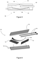
Figures 5 and 6 show respectively a partial sectional view and an exploded perspective view of another of a switch according to the present disclosure. - As mentioned, there are many applications in which signals need to be switched between one component of an apparatus and another. For example, there are many types of electrical circuits in apparatus and devices in which signals need to be switched.
- As a particular example, switches are often used in RF (radio frequency) and other switching applications, for example to switch two circuits between a single antenna or to switch one or more circuits between two (or more) antennas. It is known for example to use PIN diodes as switches in such RF applications, including for example in MIMO (multiple-input and multiple-output) techniques which use multiple antennas or to switch an antenna between transmit and receive circuits as necessary. However, PIN diodes are relatively expensive. Further, additional circuitry is required in order to drive operation of the PIN diodes. It is also known or has been proposed to use FETs (field effect transistors) or MEMs (micro-electromechanical systems) as the switches, but again these are relatively expensive to purchase and/or implement.
- In accordance with some examples of the present disclosure, there is provided a switch for use in switching signals in an apparatus. The switch is a fluid-mechanical circuit switch. That is, the switch is in essence a mechanical switch that is operated using a fluid, and specifically in examples by fluid pressure. This contrasts for example with the electronic or electromechanical switches used or proposed for use in the prior art. The switch has a fluid reservoir and (at least) two electrical contacts. The fluid reservoir expands and contracts as fluid is introduced into and removed from the fluid reservoir respectively. The electrical contacts and the fluid reservoir are arranged such that expansion and contraction of the fluid reservoir causes the electrical contacts to make and break contact respectively, or break and make contact respectively, so as to switch signals in a said apparatus.
- In some examples, the switch is used in apparatus for transmitting RF signals or receiving RF signals or transmitting and receiving RF signals. Such apparatus may have at least one antenna and at least one signal processing circuit. The switch may variously switch signals between the antenna(s) and the signal processing circuit(s) depending on the particular arrangement and function of the apparatus. Some specific examples will be discussed further below.
- In this regard, as will be appreciated, in many applications, a device may be only a transmitter or only a receiver or both a transmitter and a receiver (transmitting and receiving at different times or possibly at the same time). For brevity, reference will often only be made herein by way of example to the transmitter aspects, it being understood that this will apply similarly to the receiver aspects and/or to transceiver aspects unless the context requires otherwise.
- Referring now to
Figure 1 , this shows schematically an example of asimple circuit 10 using aswitch 12 according to the present disclosure. Theswitch 12 is shown highly schematically inFigure 1 . Specific examples of arrangements for theswitch 12 will be discussed further below. - The
circuit 10 has aninput 14 for signals at which signals are received in use and anoutput 16 from which signals are output in use. Such signals may be in general be any type of signal that is passed around an electrical circuit. As a specific example, such signals may be for example RF signals received at or to be transmitted by an antenna with which thecircuit 10 is in communication in use. Theinput 14 and theoutput 16 are electrically connected to each other and disconnected from each other by appropriate operation of theswitch 12. - Referring to
Figure 2 , this shows schematically an example of anapparatus 20 for transmitting RF signals or receiving RF signals or transmitting and receiving (i.e. transceiving) RFsignals using switches 22 according to the present disclosure. Again, theswitches 22 are shown highly schematically inFigure 2 and specific examples of arrangements for theswitches 22 will be discussed further below. - The
apparatus 20 of this example hasplural antennas 24, for receiving or transmitting or both receiving and transmitting RF signals. Theswitches 22 are arranged to enable signals to or from theantennas 24 from or to some circuitry, such as for example some transmit circuitry and/or some receive circuitry (not shown), to be switched as necessary. Theapparatus 20 may for example be used for so-called antenna diversity techniques in which theplural antennas 24 enable theapparatus 20 to have several different "observations" of the same signal, enabling multipath problems caused by reflections of the signal and the like to be mitigated. As another example, theapparatus 20 may be used for so-called beamforming techniques, in which theplural antennas 24 are used to transmit the same signal with different phases and/or amplitudes and/or theplural antennas 24 are used to receive the same signals and the outputs from theplural antennas 24 are weighted differently, in each case to control the directionality of the transmit or receive side respectively. As another example, theapparatus 20 may be used for so-called MIMO (multiple-input and multiple-output) techniques, which use theplural antennas 24 to exploit multipath propagation thereby to increase the capacity of a radio link. In each case, theswitches 22 are used to switch the various signals as and when needed to enable the desired transmission and/or reception properties to be achieved in a manner known per se. - In yet another example (not shown), the
apparatus 20 may have only asingle antenna 24 which is used for both transmit and receive, typically at different times. In such a case, there may be a transmitter signal processing circuit and a receiver signal processing circuit (not shown). Theapparatus 20 may have asingle switch 22 orplural switches 22, depending on the precise arrangement. The or eachswitch 22 is used to switch theantenna 24 between the transmitter and receiver signal processing circuits as and when necessary. - Other examples of applications for the
apparatus 20, with one orplural antennas 24 and with one orplural switches 22 are possible. - Referring now to
Figures 3 and 4 , these schematically show an example of aswitch 30 according to the present disclosure in a closed state and an open state respectively. Theswitch 30 may be used to switch signals in an electrical circuit generally, and in particular may be used to switch RF or other signals in an apparatus for transmitting RF signals or for receiving RF signals or for transmitting and receiving RF signals, including any of the examples of such apparatus discussed above. - The
switch 30 is a fluid-mechanical circuit switch, that is, a mechanical switch having contacts that are driven to make or break using a fluid, and specifically in examples by use of fluid pressure. - In the example shown, the
switch 30 has twoelectrical contacts 32. Theelectrical contacts 32 are formed of an electrically conductive material, such as for example a metal or metals, including for example copper, silver, gold, etc. Theswitch 30 has afluid reservoir 34 which contains in use afluid 36. At least a part of the wall of thefluid reservoir 34 is flexible and is arranged such that as (further)fluid 36 is introduced into thefluid reservoir 34, thefluid reservoir 34 expands so as to drive movement of theelectrical contacts 32; and, correspondingly, asfluid 36 exits thefluid reservoir 34, thefluid reservoir 34 contracts to allow theelectrical contacts 32 to relax back. - To achieve this movement of the
electrical contacts 32, in this example thefluid reservoir 34 has aflexible wall 38 which expands asfluid 36 enters thereservoir 34. In this example, theflexible wall 38 is in direct contact with theelectrical contacts 32 to drive movement of theelectrical contacts 32 directly. In other examples, theflexible wall 38 may drive movement of theelectrical contacts 32 indirectly, for example via some intermediate buffer wall and/or via some mechanical arrangement of levers and the like. The whole of the walls of thefluid reservoir 34 may be flexible. However, in the present example, there is only onewall 38 that is flexible, and the remainder of thefluid reservoir 34 is rigid. This provides for easier and more controlled movement of theflexible wall 38 as the remainder of thefluid reservoir 34 can then provide a rigid reaction wall against which the fluid 36 can act to cause theflexible wall 38 to move as desired. As well as being flexible, theflexible wall 38 may also be resilient, so that it automatically returns to its relaxed state asfluid 36 is caused to exit thefluid reservoir 34. Alternatively or additionally, the drop in pressure that arises asfluid 36 is caused to exit thefluid reservoir 34 may draw thefluid reservoir 34 inwards. - The
flexible wall 38 may be in the form of a thin membrane. Theflexible wall 38 is preferably electrically insulating. In one specific example, theflexible wall 38 may be formed of a material such as a plastics, such as for example polyethylene, a polyamide, polypropylene, a polyester, nylon, other similar thermoplastics, etc. The remainder of thefluid reservoir 34 may be formed of a relatively thick material so as to increase its rigidity. The remainder of thefluid reservoir 34 is preferably electrically insulating. The remainder of thefluid reservoir 34 may be formed for example of a rigid plastics material, including for example polycarbonate, polypropylene, polyvinyl chloride, polylactic acid (PLA), acrylonitrile butadiene styrene (ABS), polydimethylsiloxane (PDMS), poly methyl methacrylate (PMMA), etc, or a glass; or the remainder of thefluid reservoir 34 may be formed for example of a metal or mixture of metals in the case that thefluid reservoir 34 is not electrically insulating. The fluid 36 may be a liquid, though in other examples the fluid may be gaseous. In specific examples, the fluid 36 can be any fluid that has an appropriate viscosity to support capillary movement, and may be for example water, water-based solutions, oil, alcohol, or similar solutions, etc. - In this example, the
contacts 32 touch each other in their default, relaxed state and so theswitch 30 is normally closed. Accordingly, in use, to open theswitch 30 in this example,fluid 36 is introduced into thereservoir 34 as shown by the arrow inFigure 4 . This causes theflexible wall 38 to expand or bow outwards. This forces thecontacts 32 apart, so breaking the contact between thecontacts 32 and thereby opening theswitch 30. To close theswitch 30 in this example,fluid 36 is caused or allowed to exit thereservoir 34. This allows theflexible wall 38 to relax, and/or drives theflexible wall 38 owing to the drop of pressure in thereservoir 34, back again. This allows thecontacts 32 to relax back to their configuration shown inFigure 3 in which thecontacts 32 touch each other, thereby closing theswitch 32. - The
switch 30 may be of the so-called "microfluid" type. Theswitch 30 may for example have dimensions of say approximately 8mm x 12mm to 14mm x 30mm. There may be a pump (not shown) for drivingfluid 36 into thereservoir 34 and which can be operated in reverse to drawfluid 36 out of thereservoir 34. The pump may directly shiftfluid 36 around as necessary for this purpose, or may for example apply high pressure and low (vacuum) pressure as necessary to drive fluid 36 in and out of thereservoir 34. The pump is a high pressure pump for a continuous control system. Alternatively, the pump may be a droplet-based pump. - The
switch 30 in some examples may be mounted on a PCB (printed circuit board). The PCB may also contain other components, including for example a transmitter signal processing circuit and/or a receiver signal processing circuit. This is of advantage as the entirety of the processing circuit(s) and switch(es) can be built onto a single PCB, which greatly facilitates installation of the circuity in some overall apparatus. - Referring now to
Figures 5 and 6 , these schematically show another example of a fluid-mechanical switch 50 according to the present disclosure. Theswitch 50 may again be used to switch signals in an electrical circuit generally, and in particular may be used to switch RF or other signals in an apparatus for transmitting RF signals or for receiving RF signals or for transmitting and receiving RF signals, including any of the examples of such apparatus discussed above. - Many of the parts of the
switch 50 ofFigures 5 and 6 may be made of the same materials as and be arranged similarly to theswitch 30 ofFigures 3 and 4 . Likewise, theswitch 50 ofFigures 5 and 6 may be implemented in applications like those of theswitch 30 ofFigures 3 and 4 and described above. The description of such materials, arrangements and applications will not be repeated here for brevity. - In the example shown, the
switch 50 has twoelectrical contacts 52 of an electrically conductive material. Respectiveelectrical contact wires 53 are connected to thecontacts 52. Theswitch 50 has afluid reservoir 54 which contains in use afluid 56. At least a part of the wall of thefluid reservoir 54 is flexible and is arranged such that as (further)fluid 56 is introduced into thefluid reservoir 54, thefluid reservoir 54 expands so as to drive movement of theelectrical contacts 52; and, correspondingly, asfluid 56 exits thefluid reservoir 54, thefluid reservoir 54 contracts to allow theelectrical contacts 32 to relax back. - To achieve this movement of the
electrical contacts 52, in this example thefluid reservoir 54 has aflexible wall 58 which expands asfluid 56 enters thereservoir 54. In this example, theflexible wall 58 is again in direct contact with theelectrical contacts 52 to drive movement of theelectrical contacts 52 directly. In other examples, theflexible wall 58 may drive movement of theelectrical contacts 52 indirectly, for example via some intermediate buffer wall and/or via some mechanical arrangement of levers and the like. The whole of the walls of thefluid reservoir 54 may be flexible. However, in the present example, there is only onewall 58 that is flexible, and the remainder of thefluid reservoir 54 is rigid. For example, in this case theswitch 50 has a rigid "top"wall 55 and rigid side walls (not shown) which form the other walls of thefluid reservoir 54. This provides for easier and more controlled movement of theflexible wall 58 as the remainder of thefluid reservoir 54 can then provide a rigid reaction wall against which the fluid 56 can act to cause theflexible wall 58 to move as desired. As well as being flexible, theflexible wall 58 may also be resilient, so that it automatically returns to its relaxed state asfluid 56 is caused to exit thefluid reservoir 54. Alternatively or additionally, the drop in pressure that arises asfluid 56 is caused to exit thefluid reservoir 54 may draw thefluid reservoir 54 inwards. - The
flexible wall 58 may be in the form of a thin membrane. Theflexible wall 58 is preferably electrically insulating. The remainder of thefluid reservoir 54 may be formed of a relatively thick material so as to increase its rigidity. The remainder of thefluid reservoir 54 is preferably electrically insulating. The fluid 56 may be a liquid, though in other examples the fluid may be gaseous. - In this example, the
contacts 52 do not touch each other in their default, relaxed state and so theswitch 50 is normally open. At that point, only one of thecontacts 52 is in contact with theflexible wall 58. In use, to close theswitch 50 in this example,fluid 56 is introduced into thereservoir 54. This causes theflexible wall 58 to expand or bow outwards. In this example, this forces the onecontact 52 outwards, causing thatcontact 52 to touch the other contact, and thereby closing theswitch 50. To open theswitch 50 in this example,fluid 56 is caused or allowed to exit thereservoir 54. This allows theflexible wall 58 to relax, and/or drives theflexible wall 58 owing to the drop of pressure in thereservoir 54, back again. This allows thecontacts 52 to relax back to their configuration shown inFigure 5 in which thecontacts 52 do mot touch each other, thereby opening theswitch 52. - The
switch 50 may again be of the so-called "microfluid" type. There may be a pump (not shown) for drivingfluid 56 into thereservoir 54 and which can be operated in reverse to drawfluid 56 out of thereservoir 54. The pump may directly shiftfluid 56 around as necessary for this purpose, or may for example apply high pressure and low (vacuum) pressure as necessary to drive fluid 56 in and out of thereservoir 54. Further, in this example, compared to the single entry/exit pipe or channel forfluid 36 in the example ofFigures 3 and 4 , in this example, there are two pipes orchannels 59 in fluid communication with thereservoir 54 for pumpingfluid 56 in and out of thereservoir 54. In one example, onepipe 59 may be for fluid in and theother pipe 59 may be for fluid out. Alternatively or additionally, the direction of fluid flow through thepipes 59 may be reversed to enable fluid 56 to be pumped in and out. - The
switch 50 in some examples may again be mounted on a PCB (printed circuit board). The PCB may also contain other components, including for example a transmitter signal processing circuit and/or a receiver signal processing circuit. This is of advantage as the entirety of the processing circuit(s) and switch(es) can be built onto a single PCB, which greatly facilitates installation of the circuity in some overall apparatus. - As mentioned, switches 30, 50 according to the present disclosure can be less expensive to implement than for example PIN diodes or FETs (field effect transistors) or MEMs (micro-electromechanical systems), which for example are used or have been proposed for use in some existing RF switching applications. In this regard, it is noted that the switching speed of
switches - The examples described herein are to be understood as illustrative examples of embodiments of the invention. Further embodiments and examples are envisaged. Any feature described in relation to any one example or embodiment may be used alone or in combination with other features. In addition, any feature described in relation to any one example or embodiment may also be used in combination with one or more features of any other of the examples or embodiments, or any combination of any other of the examples or embodiments. Furthermore, equivalents and modifications not described herein may also be employed within the scope of the invention, which is defined in the claims.
Claims (11)
- A switch for use in switching signals in an apparatus, the switch being a fluid-mechanical circuit switch and comprising:a fluid reservoir; andtwo electrical contacts;wherein the fluid reservoir is constructed and arranged such that the fluid reservoir expands and contracts as fluid is introduced into and removed from the fluid reservoir respectively, the electrical contacts and the fluid reservoir being arranged such that expansion and contraction of the fluid reservoir causes the electrical contacts to make and break contact respectively, or break and make contact respectively, so as to switch signals in a said apparatus.
- A switch according to claim 1, wherein the fluid reservoir comprises a flexible wall, the flexible wall being arranged so as to bow outwards as fluid is introduced into the fluid reservoir so as to drive movement of the electrical contacts to make or break contact between the electrical contacts as the case may be.
- A switch according to claim 2, wherein the flexible wall of the fluid reservoir contacts the electrical contacts so as to drive movement of the electrical contacts as the flexible wall bows outwards.
- A switch according to any of claims 1 to 3, comprising a first fluid line for conveying fluid into the reservoir and a second fluid line for conveying fluid out of the reservoir.
- Apparatus for transmitting RF signals or receiving RF signals or transmitting and receiving RF signals, the apparatus comprising:at least one antenna;at least one signal processing circuit, the signal processing circuit being at least one of a transmitter circuit and a receiver circuit; anda switch for switching signals in the apparatus, the switch being arranged to switch the signal processing circuit between two antennas in the case that the apparatus comprises at least two antennas, or the switch being arranged to switch the antenna between two signal processing circuits in the case that the apparatus comprises at least two signal processing circuits;wherein the switch is a fluid-mechanical circuit switch, the fluid-mechanical circuit switch comprising two electrical contacts and a fluid reservoir, wherein the fluid reservoir is constructed and arranged such that the fluid reservoir expands and contracts as fluid is introduced into and removed from the fluid reservoir respectively, the electrical contacts and the fluid reservoir being arranged such that expansion and contraction of the fluid reservoir causes the electrical contacts to make and break contact respectively, or break and make contact respectively, so as to switch signals in the apparatus.
- Apparatus according to claim 5, wherein the fluid reservoir comprises a flexible wall, the flexible wall being arranged so as to bow outwards as fluid is introduced into the fluid reservoir so as to drive movement of the electrical contacts to make or break contact between the electrical contacts as the case may be.
- Apparatus according to claim 6, wherein the flexible wall of the fluid reservoir contacts the electrical contacts so as to drive movement of the electrical contacts as the flexible wall bows outwards.
- Apparatus according to any of claims 5 to 7, comprising a first fluid line for conveying fluid into the reservoir and a second fluid line for conveying fluid out of the reservoir.
- Apparatus according to any of claims 5 to 8, comprising a pump for pumping fluid into the fluid reservoir.
- A satellite comprising:at least two antennas;at least one signal processing circuit, the signal processing circuit being at least one of a transmitter circuit and a receiver circuit;a switch according to any of claims 1 to 4, the switch being operable to switch the signal processing circuit between the antennas.
- A satellite according to claim 10, the satellite comprising a pump for pumping fluid into the fluid reservoir of the switch.
Priority Applications (1)
| Application Number | Priority Date | Filing Date | Title |
|---|---|---|---|
| EP20196036.6A EP3968348A1 (en) | 2020-09-14 | 2020-09-14 | Switch for use in switching signals and apparatus for transmitting or receiving rf signals |
Applications Claiming Priority (1)
| Application Number | Priority Date | Filing Date | Title |
|---|---|---|---|
| EP20196036.6A EP3968348A1 (en) | 2020-09-14 | 2020-09-14 | Switch for use in switching signals and apparatus for transmitting or receiving rf signals |
Publications (1)
| Publication Number | Publication Date |
|---|---|
| EP3968348A1 true EP3968348A1 (en) | 2022-03-16 |
Family
ID=72517106
Family Applications (1)
| Application Number | Title | Priority Date | Filing Date |
|---|---|---|---|
| EP20196036.6A Withdrawn EP3968348A1 (en) | 2020-09-14 | 2020-09-14 | Switch for use in switching signals and apparatus for transmitting or receiving rf signals |
Country Status (1)
| Country | Link |
|---|---|
| EP (1) | EP3968348A1 (en) |
Citations (4)
| Publication number | Priority date | Publication date | Assignee | Title |
|---|---|---|---|---|
| GB2003324A (en) * | 1977-08-27 | 1979-03-07 | Bosch Siemens Hausgeraete | Fluid pressure actuated switch |
| US4239979A (en) * | 1977-05-12 | 1980-12-16 | Compagnie Generale Des Etablissements Michelin | Membrane contactor |
| US20040076531A1 (en) * | 2001-11-19 | 2004-04-22 | Ngk Insulators, Ltd. | Circuit changeover switch |
| US20120222944A1 (en) * | 2009-11-12 | 2012-09-06 | Postech Academy-Industry Foundation | Rf mems switch using change in shape of fine liquid metal droplet |
-
2020
- 2020-09-14 EP EP20196036.6A patent/EP3968348A1/en not_active Withdrawn
Patent Citations (4)
| Publication number | Priority date | Publication date | Assignee | Title |
|---|---|---|---|---|
| US4239979A (en) * | 1977-05-12 | 1980-12-16 | Compagnie Generale Des Etablissements Michelin | Membrane contactor |
| GB2003324A (en) * | 1977-08-27 | 1979-03-07 | Bosch Siemens Hausgeraete | Fluid pressure actuated switch |
| US20040076531A1 (en) * | 2001-11-19 | 2004-04-22 | Ngk Insulators, Ltd. | Circuit changeover switch |
| US20120222944A1 (en) * | 2009-11-12 | 2012-09-06 | Postech Academy-Industry Foundation | Rf mems switch using change in shape of fine liquid metal droplet |
Similar Documents
| Publication | Publication Date | Title |
|---|---|---|
| EP1529301B1 (en) | Buckling beam bi-stable microelectromechanical switch using electro-thermal actuation | |
| AU2017417125B2 (en) | Multi-antenna system | |
| EP2230713B1 (en) | Switchable 0 degree/180 degree phase shifter on flexible coplanar strip transmission line | |
| WO2001013457A1 (en) | Electrical switches | |
| US20040198229A1 (en) | Antenna apparatus and electronic equipment having antenna apparatus | |
| US20050093753A1 (en) | Information device | |
| MY149574A (en) | Channel switching circuit | |
| EP1868298A3 (en) | Switch and switsching device with selective isolation for multimedia terminals | |
| US6825737B2 (en) | Device for broadband electrical signal transmission using a bi-directional transmission system | |
| KR100848261B1 (en) | Device containing RF switch and RF switch | |
| TR202014498A2 (en) | Switch for use in switching signals and apparatus for transmitting or receiving rf signals. | |
| US7212101B2 (en) | Device for broadband electrical signal and/or energy transmission using a transmission system including couplers | |
| US10615497B2 (en) | Splitter circuit and antenna | |
| US7012354B2 (en) | Method and structure for a pusher-mode piezoelectrically actuated liquid metal switch | |
| WO2019013812A1 (en) | Antenna ports including switch type radio frequency connectors | |
| CN115225096A (en) | Multiple Antenna Arrangements | |
| US7010272B2 (en) | Double-port multi-through RF switch | |
| US7855616B2 (en) | Radio frequency switch | |
| KR20140114107A (en) | Apparatus for RS-232C and RS-485 Serial Communication using Common Communication Port | |
| KR970002046A (en) | Hydraulic control device of automatic transmission | |
| KR100270227B1 (en) | Low noise antenna switching diversity apparatus having adjusted threshold level | |
| US20040200708A1 (en) | Method and structure for a slug assisted pusher-mode piezoelectrically actuated liquid metal optical switch | |
| Cetiner et al. | A MIMO system equipped with multifunctional reconfigurable antennas | |
| WO2022099502A1 (en) | Phase shifter and antenna device | |
| WO2003063361A1 (en) | Membrane switch with transmitter |
Legal Events
| Date | Code | Title | Description |
|---|---|---|---|
| PUAI | Public reference made under article 153(3) epc to a published international application that has entered the european phase |
Free format text: ORIGINAL CODE: 0009012 |
|
| STAA | Information on the status of an ep patent application or granted ep patent |
Free format text: STATUS: THE APPLICATION HAS BEEN PUBLISHED |
|
| AK | Designated contracting states |
Kind code of ref document: A1 Designated state(s): AL AT BE BG CH CY CZ DE DK EE ES FI FR GB GR HR HU IE IS IT LI LT LU LV MC MK MT NL NO PL PT RO RS SE SI SK SM TR |
|
| STAA | Information on the status of an ep patent application or granted ep patent |
Free format text: STATUS: THE APPLICATION IS DEEMED TO BE WITHDRAWN |
|
| 18D | Application deemed to be withdrawn |
Effective date: 20220917 |