EP3968318A1 - Display device and method of operating the same - Google Patents
Display device and method of operating the same Download PDFInfo
- Publication number
- EP3968318A1 EP3968318A1 EP20210003.8A EP20210003A EP3968318A1 EP 3968318 A1 EP3968318 A1 EP 3968318A1 EP 20210003 A EP20210003 A EP 20210003A EP 3968318 A1 EP3968318 A1 EP 3968318A1
- Authority
- EP
- European Patent Office
- Prior art keywords
- scan rate
- image frame
- porch
- value
- vertical
- Prior art date
- Legal status (The legal status is an assumption and is not a legal conclusion. Google has not performed a legal analysis and makes no representation as to the accuracy of the status listed.)
- Pending
Links
- 238000000034 method Methods 0.000 title claims description 32
- 238000010586 diagram Methods 0.000 description 10
- 239000004973 liquid crystal related substance Substances 0.000 description 3
- 239000011159 matrix material Substances 0.000 description 2
- 230000004044 response Effects 0.000 description 2
- 230000001360 synchronised effect Effects 0.000 description 2
- XUIMIQQOPSSXEZ-UHFFFAOYSA-N Silicon Chemical compound [Si] XUIMIQQOPSSXEZ-UHFFFAOYSA-N 0.000 description 1
- 238000004891 communication Methods 0.000 description 1
- 238000013500 data storage Methods 0.000 description 1
- 230000003111 delayed effect Effects 0.000 description 1
- 230000000694 effects Effects 0.000 description 1
- 238000005516 engineering process Methods 0.000 description 1
- 230000005669 field effect Effects 0.000 description 1
- 239000011521 glass Substances 0.000 description 1
- 230000002452 interceptive effect Effects 0.000 description 1
- 230000003287 optical effect Effects 0.000 description 1
- 230000002093 peripheral effect Effects 0.000 description 1
- 230000036632 reaction speed Effects 0.000 description 1
- 239000004065 semiconductor Substances 0.000 description 1
- 229910052710 silicon Inorganic materials 0.000 description 1
- 239000010703 silicon Substances 0.000 description 1
- 239000007787 solid Substances 0.000 description 1
- 239000000758 substrate Substances 0.000 description 1
Images

Classifications
-
- G—PHYSICS
- G09—EDUCATION; CRYPTOGRAPHY; DISPLAY; ADVERTISING; SEALS
- G09G—ARRANGEMENTS OR CIRCUITS FOR CONTROL OF INDICATING DEVICES USING STATIC MEANS TO PRESENT VARIABLE INFORMATION
- G09G5/00—Control arrangements or circuits for visual indicators common to cathode-ray tube indicators and other visual indicators
- G09G5/10—Intensity circuits
-
- G—PHYSICS
- G09—EDUCATION; CRYPTOGRAPHY; DISPLAY; ADVERTISING; SEALS
- G09G—ARRANGEMENTS OR CIRCUITS FOR CONTROL OF INDICATING DEVICES USING STATIC MEANS TO PRESENT VARIABLE INFORMATION
- G09G3/00—Control arrangements or circuits, of interest only in connection with visual indicators other than cathode-ray tubes
- G09G3/20—Control arrangements or circuits, of interest only in connection with visual indicators other than cathode-ray tubes for presentation of an assembly of a number of characters, e.g. a page, by composing the assembly by combination of individual elements arranged in a matrix no fixed position being assigned to or needed to be assigned to the individual characters or partial characters
- G09G3/34—Control arrangements or circuits, of interest only in connection with visual indicators other than cathode-ray tubes for presentation of an assembly of a number of characters, e.g. a page, by composing the assembly by combination of individual elements arranged in a matrix no fixed position being assigned to or needed to be assigned to the individual characters or partial characters by control of light from an independent source
- G09G3/36—Control arrangements or circuits, of interest only in connection with visual indicators other than cathode-ray tubes for presentation of an assembly of a number of characters, e.g. a page, by composing the assembly by combination of individual elements arranged in a matrix no fixed position being assigned to or needed to be assigned to the individual characters or partial characters by control of light from an independent source using liquid crystals
- G09G3/3611—Control of matrices with row and column drivers
- G09G3/3648—Control of matrices with row and column drivers using an active matrix
-
- G—PHYSICS
- G09—EDUCATION; CRYPTOGRAPHY; DISPLAY; ADVERTISING; SEALS
- G09G—ARRANGEMENTS OR CIRCUITS FOR CONTROL OF INDICATING DEVICES USING STATIC MEANS TO PRESENT VARIABLE INFORMATION
- G09G3/00—Control arrangements or circuits, of interest only in connection with visual indicators other than cathode-ray tubes
- G09G3/20—Control arrangements or circuits, of interest only in connection with visual indicators other than cathode-ray tubes for presentation of an assembly of a number of characters, e.g. a page, by composing the assembly by combination of individual elements arranged in a matrix no fixed position being assigned to or needed to be assigned to the individual characters or partial characters
- G09G3/2092—Details of a display terminals using a flat panel, the details relating to the control arrangement of the display terminal and to the interfaces thereto
-
- G—PHYSICS
- G09—EDUCATION; CRYPTOGRAPHY; DISPLAY; ADVERTISING; SEALS
- G09G—ARRANGEMENTS OR CIRCUITS FOR CONTROL OF INDICATING DEVICES USING STATIC MEANS TO PRESENT VARIABLE INFORMATION
- G09G3/00—Control arrangements or circuits, of interest only in connection with visual indicators other than cathode-ray tubes
- G09G3/20—Control arrangements or circuits, of interest only in connection with visual indicators other than cathode-ray tubes for presentation of an assembly of a number of characters, e.g. a page, by composing the assembly by combination of individual elements arranged in a matrix no fixed position being assigned to or needed to be assigned to the individual characters or partial characters
- G09G3/34—Control arrangements or circuits, of interest only in connection with visual indicators other than cathode-ray tubes for presentation of an assembly of a number of characters, e.g. a page, by composing the assembly by combination of individual elements arranged in a matrix no fixed position being assigned to or needed to be assigned to the individual characters or partial characters by control of light from an independent source
- G09G3/3406—Control of illumination source
-
- G—PHYSICS
- G09—EDUCATION; CRYPTOGRAPHY; DISPLAY; ADVERTISING; SEALS
- G09G—ARRANGEMENTS OR CIRCUITS FOR CONTROL OF INDICATING DEVICES USING STATIC MEANS TO PRESENT VARIABLE INFORMATION
- G09G3/00—Control arrangements or circuits, of interest only in connection with visual indicators other than cathode-ray tubes
- G09G3/20—Control arrangements or circuits, of interest only in connection with visual indicators other than cathode-ray tubes for presentation of an assembly of a number of characters, e.g. a page, by composing the assembly by combination of individual elements arranged in a matrix no fixed position being assigned to or needed to be assigned to the individual characters or partial characters
- G09G3/34—Control arrangements or circuits, of interest only in connection with visual indicators other than cathode-ray tubes for presentation of an assembly of a number of characters, e.g. a page, by composing the assembly by combination of individual elements arranged in a matrix no fixed position being assigned to or needed to be assigned to the individual characters or partial characters by control of light from an independent source
- G09G3/3406—Control of illumination source
- G09G3/342—Control of illumination source using several illumination sources separately controlled corresponding to different display panel areas, e.g. along one dimension such as lines
- G09G3/3426—Control of illumination source using several illumination sources separately controlled corresponding to different display panel areas, e.g. along one dimension such as lines the different display panel areas being distributed in two dimensions, e.g. matrix
-
- G—PHYSICS
- G09—EDUCATION; CRYPTOGRAPHY; DISPLAY; ADVERTISING; SEALS
- G09G—ARRANGEMENTS OR CIRCUITS FOR CONTROL OF INDICATING DEVICES USING STATIC MEANS TO PRESENT VARIABLE INFORMATION
- G09G3/00—Control arrangements or circuits, of interest only in connection with visual indicators other than cathode-ray tubes
- G09G3/20—Control arrangements or circuits, of interest only in connection with visual indicators other than cathode-ray tubes for presentation of an assembly of a number of characters, e.g. a page, by composing the assembly by combination of individual elements arranged in a matrix no fixed position being assigned to or needed to be assigned to the individual characters or partial characters
- G09G3/34—Control arrangements or circuits, of interest only in connection with visual indicators other than cathode-ray tubes for presentation of an assembly of a number of characters, e.g. a page, by composing the assembly by combination of individual elements arranged in a matrix no fixed position being assigned to or needed to be assigned to the individual characters or partial characters by control of light from an independent source
- G09G3/36—Control arrangements or circuits, of interest only in connection with visual indicators other than cathode-ray tubes for presentation of an assembly of a number of characters, e.g. a page, by composing the assembly by combination of individual elements arranged in a matrix no fixed position being assigned to or needed to be assigned to the individual characters or partial characters by control of light from an independent source using liquid crystals
-
- G—PHYSICS
- G09—EDUCATION; CRYPTOGRAPHY; DISPLAY; ADVERTISING; SEALS
- G09G—ARRANGEMENTS OR CIRCUITS FOR CONTROL OF INDICATING DEVICES USING STATIC MEANS TO PRESENT VARIABLE INFORMATION
- G09G3/00—Control arrangements or circuits, of interest only in connection with visual indicators other than cathode-ray tubes
- G09G3/20—Control arrangements or circuits, of interest only in connection with visual indicators other than cathode-ray tubes for presentation of an assembly of a number of characters, e.g. a page, by composing the assembly by combination of individual elements arranged in a matrix no fixed position being assigned to or needed to be assigned to the individual characters or partial characters
- G09G3/34—Control arrangements or circuits, of interest only in connection with visual indicators other than cathode-ray tubes for presentation of an assembly of a number of characters, e.g. a page, by composing the assembly by combination of individual elements arranged in a matrix no fixed position being assigned to or needed to be assigned to the individual characters or partial characters by control of light from an independent source
- G09G3/36—Control arrangements or circuits, of interest only in connection with visual indicators other than cathode-ray tubes for presentation of an assembly of a number of characters, e.g. a page, by composing the assembly by combination of individual elements arranged in a matrix no fixed position being assigned to or needed to be assigned to the individual characters or partial characters by control of light from an independent source using liquid crystals
- G09G3/3611—Control of matrices with row and column drivers
-
- G—PHYSICS
- G09—EDUCATION; CRYPTOGRAPHY; DISPLAY; ADVERTISING; SEALS
- G09G—ARRANGEMENTS OR CIRCUITS FOR CONTROL OF INDICATING DEVICES USING STATIC MEANS TO PRESENT VARIABLE INFORMATION
- G09G5/00—Control arrangements or circuits for visual indicators common to cathode-ray tube indicators and other visual indicators
- G09G5/003—Details of a display terminal, the details relating to the control arrangement of the display terminal and to the interfaces thereto
- G09G5/006—Details of the interface to the display terminal
-
- G—PHYSICS
- G09—EDUCATION; CRYPTOGRAPHY; DISPLAY; ADVERTISING; SEALS
- G09G—ARRANGEMENTS OR CIRCUITS FOR CONTROL OF INDICATING DEVICES USING STATIC MEANS TO PRESENT VARIABLE INFORMATION
- G09G2320/00—Control of display operating conditions
- G09G2320/02—Improving the quality of display appearance
- G09G2320/0233—Improving the luminance or brightness uniformity across the screen
-
- G—PHYSICS
- G09—EDUCATION; CRYPTOGRAPHY; DISPLAY; ADVERTISING; SEALS
- G09G—ARRANGEMENTS OR CIRCUITS FOR CONTROL OF INDICATING DEVICES USING STATIC MEANS TO PRESENT VARIABLE INFORMATION
- G09G2320/00—Control of display operating conditions
- G09G2320/06—Adjustment of display parameters
- G09G2320/0626—Adjustment of display parameters for control of overall brightness
-
- G—PHYSICS
- G09—EDUCATION; CRYPTOGRAPHY; DISPLAY; ADVERTISING; SEALS
- G09G—ARRANGEMENTS OR CIRCUITS FOR CONTROL OF INDICATING DEVICES USING STATIC MEANS TO PRESENT VARIABLE INFORMATION
- G09G2320/00—Control of display operating conditions
- G09G2320/06—Adjustment of display parameters
- G09G2320/0626—Adjustment of display parameters for control of overall brightness
- G09G2320/0646—Modulation of illumination source brightness and image signal correlated to each other
-
- G—PHYSICS
- G09—EDUCATION; CRYPTOGRAPHY; DISPLAY; ADVERTISING; SEALS
- G09G—ARRANGEMENTS OR CIRCUITS FOR CONTROL OF INDICATING DEVICES USING STATIC MEANS TO PRESENT VARIABLE INFORMATION
- G09G2340/00—Aspects of display data processing
- G09G2340/04—Changes in size, position or resolution of an image
- G09G2340/0407—Resolution change, inclusive of the use of different resolutions for different screen areas
- G09G2340/0414—Vertical resolution change
-
- G—PHYSICS
- G09—EDUCATION; CRYPTOGRAPHY; DISPLAY; ADVERTISING; SEALS
- G09G—ARRANGEMENTS OR CIRCUITS FOR CONTROL OF INDICATING DEVICES USING STATIC MEANS TO PRESENT VARIABLE INFORMATION
- G09G2340/00—Aspects of display data processing
- G09G2340/04—Changes in size, position or resolution of an image
- G09G2340/0407—Resolution change, inclusive of the use of different resolutions for different screen areas
- G09G2340/0435—Change or adaptation of the frame rate of the video stream
-
- G—PHYSICS
- G09—EDUCATION; CRYPTOGRAPHY; DISPLAY; ADVERTISING; SEALS
- G09G—ARRANGEMENTS OR CIRCUITS FOR CONTROL OF INDICATING DEVICES USING STATIC MEANS TO PRESENT VARIABLE INFORMATION
- G09G2360/00—Aspects of the architecture of display systems
- G09G2360/16—Calculation or use of calculated indices related to luminance levels in display data
-
- G—PHYSICS
- G09—EDUCATION; CRYPTOGRAPHY; DISPLAY; ADVERTISING; SEALS
- G09G—ARRANGEMENTS OR CIRCUITS FOR CONTROL OF INDICATING DEVICES USING STATIC MEANS TO PRESENT VARIABLE INFORMATION
- G09G2370/00—Aspects of data communication
- G09G2370/10—Use of a protocol of communication by packets in interfaces along the display data pipeline
Definitions
- the present disclosure relates to a display device and a method of operating the same, and more particularly, to a display device for controlling luminance of a display panel and a method of operating the same.
- a display device for reproducing a game video may display more scenes during the same period of time than a display device operating at a scan rate of 60 Hz.
- a user may feel a much smoother screen as the refresh rate is higher, and in a game that requires a fast reaction speed, a higher scan rate is required.
- a tearing phenomenon in which the screen is sheared horizontally may occur.
- the tearing phenomenon occurs when an image frame output by a graphic card and an image frame output by a display panel are not synchronized in a case where the scan rates of images are fixed.
- variable scan rate or variable refresh rate, VRR
- VRR variable refresh rate
- a conventional liquid crystal display device controls the overall brightness of a screen through a pulse width modulation (PWM) signal, and controls backlight units with local dimming operation through serial peripheral interface (SPI) communication.
- PWM pulse width modulation
- SPI serial peripheral interface
- An object of the present disclosure is to prevent flickering by reducing a change in luminance according to a change in an image frequency during a variable refresh rate (VRR) operation.
- VRR variable refresh rate
- Another object of the present disclosure is to prevent flickering by reducing a change in luminance according to a change in an image frequency during a variable refresh rate (VRR) operation in an HDMI game mode.
- VRR variable refresh rate
- a display device may determines a scan rate of the image frame received through the external input interface, determine whether the determined scan rate is equal to a scan rate of a previous image frame, and when the determined scan rate is different from the scan rate of the previous image frame, and control a dimming value of the backlight unit based on the determined scan rate of the image frame.
- the display device may calculate a value of a vertical front porch constituting the image frame and determine a scan rate of the image frame using the calculated value of the vertical front porch.
- the display device may further include a memory configured to store a table showing a correspondence relationship between a resolution, a maximum vertical front porch value and a scan rate, and the display device may determine a scan rate of the image frame matching the calculated value of the vertical front porch using the table.
- the image frame may include information on the resolution, and the display device may determine a scan rate of the image frame matching the resolution and the maximum vertical front porch value greater than or equal to the calculated value of the vertical front porch.
- occurrence of flickering is suppressed when playing a game video, thereby enabling a user to watch a natural game video.
- FIG. 1 is a diagram illustrating a display device according to an embodiment of the present disclosure.
- the display device 100 of FIG. 1 may be any one of a monitor, a TV, a tablet PC, and a mobile terminal.
- the display device 100 may include an external input interface 110, a processor 111, a display panel 160, and a backlight unit 200.
- the external input interface 110 may receive image data from an external device.
- the external input interface 110 may include one or more HDMI terminals and one or more A/V terminals.
- the display panel 160 may be a liquid crystal display panel.
- the display panel 160 may display an image based on an image signal input from the external input interface 110.
- the display panel 160 may include a plurality of data lines DL1 to DLm and a plurality of gate lines GL1 to GLn which are intersected in a matrix form on a glass substrate, and a plurality of pixels corresponding to intersections.
- Each of the plurality of pixels may output an image based on an image signal provided from a source driver 150, a driving signal provided to a gate driver 140, and light provided from the backlight unit 200.
- the memory 170 may store programs and information necessary for driving the display panel 160.
- the backlight unit 200 may provide light to the display panel 160.
- the external input interface 110 may receive a control signal including one or more of image data (RGB Data), a clock signal, a horizontal synchronization signal, a vertical synchronization signal, and a data enable signal from an external device.
- RGB Data image data
- clock signal a clock signal
- horizontal synchronization signal a horizontal synchronization signal
- vertical synchronization signal a vertical synchronization signal
- data enable signal a data enable signal
- the horizontal synchronization signal may be a signal for performing synchronization in the horizontal direction of a screen.
- the vertical synchronization signal may be a signal for performing synchronization in the vertical direction of the screen.
- the data enable signal may indicate a period of supplying data to a pixel.
- the external input interface 110 may be included in the processor 111.
- the processor 111 may include a timing controller 120, a power voltage generator 130, a gate driver 140, and a source driver 150.
- the timing controller 120 may generate driving signals for driving the gate driver 140 including a plurality of driver integrated circuits and the source driver 150 including a plurality of driver integrated circuits, by using a control signal received from the external input interface 110.
- a driving signal for driving the gate driver 140 may include a high signal, a gate low signal, a clock signal, a start signal, a reset signal, and the like.
- the power voltage generator 130 may supply a power voltage, a reference voltage, a ground voltage, and the like necessary for the operation of each component included in the processor 111.
- the power voltage generator 130 may supply a common voltage corresponding to the reference voltage to the display panel 160.
- the power voltage generator 130 may supply DC power (LED B+) required for driving the backlight unit 200.
- the gate driver 140 may perform on/off control of each of the plurality of pixels included in the display panel 160, in response to a driving signal input from the timing controller 120.
- the gate driver 140 may sequentially enable the gate lines GL1 to GLn on the display panel 160 for one horizontal synchronization time by outputting gate driving signals Vg1 to Vgn.
- image signals supplied from the source driver 150 may be applied to each pixel.
- the source driver 150 may apply an image signal to each pixel in response to a data signal and a driving signal input from the timing controller 120.
- the backlight unit 200 may be arranged on one surface of the display panel 160 to provide light to the display panel 160.
- the backlight unit 200 may include a lamp unit 210 and an LED driving circuit 230.
- the lamp unit 210 may provide light to the display panel 160.
- the lamp unit 210 may provide light to the display panel 160 such that the display panel 160 implements a high dynamic range (HDR) image under the control of the LED driving circuit 230.
- HDR high dynamic range
- the local dimming may be a method of turning on or off a light in a specific area of the screen.
- the local dimming may be used to implement an HDR image.
- the lamp unit 210 may include a plurality of channels. Each of the channels may include one or more LED elements connected in series, a dimming circuit and a resistor.
- Each LED element may emit red, green, or blue monochromatic light, or may emit white light.
- the dimming circuit may be a semiconductor switch capable of turning on or off one or more LED elements.
- the dimming circuit may be composed of field effect transistors (FETs).
- FETs field effect transistors
- the resistor may be used to measure a current flowing through one channel.
- a DC voltage supplied from the power voltage generator 130 to the lamp unit 210 may be dropped by passing through one or more LED elements, and the dropped voltage may be applied to the resistor.
- a current flowing through the channel may be measured.
- the plurality of channels may be connected in parallel and may be electrically connected to the LED driving circuit 230.
- the LED driving circuit 230 may control the operation of the lamp unit 210.
- the LED driving circuit 230 may include a plurality of LED drivers.
- the number of LED drivers included in the LED driving circuit 230 may be less than the number of channels included in the lamp unit 210.
- the number of LED drivers may be equal to the number of dimming circuits. That is, the number of dimming circuits may also be less than the number of channels.
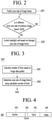
- FIG. 2 is a flowchart for describing a method for controlling luminance of a display device according to an embodiment of the present disclosure.
- a frequency may mean a scan rate of an image frame.
- the processor 111 of the display device 100 may predict a scan rate of an image frame (S201).
- the external input interface 110 may receive an image signal or an image frame from a connected external device.
- the external input interface may include one or more HDMI (High Definition Multimedia Interface) terminals or one or more A/V terminals.
- HDMI High Definition Multimedia Interface
- An external device connected to the external input interface 110 may change a frequency and output an image frame. That is, the external input interface 110 may receive an image frame whose frequency varies over time.
- the external device may transmit the image frame to the display device 100 after including information indicating that a variable scan rate is applied to the image frame in the image frame.
- the processor 111 may predict the scan rate of the image frame based on an image data packet received through the external input interface 110.
- FIG. 3 is a flowchart for describing a method of predicting a scan rate of an image frame according to an embodiment of the present disclosure.
- the processor 111 of the display device 100 may calculate the number of lines based on the image data packet received from the external input interface 110 (S301).
- the image data packet may include information indicating a change in the scan rate.
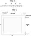
- FIG. 4 is a diagram for describing the structure of an image data packet to which a variable scan rate is not applied
- FIG. 5 is a diagram for describing the structure of an image data packet to which a variable scan rate is applied
- FIG. 6 is a diagram for describing the concept of a display panel having a resolution of 640 X 480.
- a first vertical image data packet 400 may include a vertical active porch 410, a vertical front porch 420, a vertical sync porch 430, and a vertical back porch 440.
- the first image data packet 400 of FIG. 4 may have the structure of an image data packet to which a variable scan rate is not applied.
- the vertical active porch 410 may be a section including data on an actual image to be displayed on a screen.
- the front porch 420 may be a section indicating a waiting time after output of a vertical signal.
- the vertical signal may be a signal corresponding to the vertical active porch 410.
- the vertical sync porch 430 may be a section for synchronizing vertical signals.
- the vertical back porch 440 may be a section indicating a vertical signal output waiting time for which waiting is performed until the next vertical signal is output.
- the sum of the vertical front porch 420, the vertical sync porch 430, and the vertical back porch 440 may be referred to as a vertical blank porch.
- the first image data packet 400 may be the sum of the vertical active porch and the vertical blank porch.
- the section of the vertical front porch 420 of the first image data packet 400 may be fixed.
- the second vertical image data packet 500 may include a vertical active porch 510, a vertical front porch 520, a vertical sync porch 530, and a vertical back porch 540.
- the sum of the vertical front porch 520, the vertical sync porch 530, and the vertical back porch 540 may be referred to as a vertical blank porch.
- the first image data packet 500 may be the sum of the vertical active porch and the vertical blank porch.
- the vertical active porch 510 may be a section including data on an actual image to be displayed on a screen.
- the front porch 520 may be a section indicating a waiting time after output of a vertical signal.
- the vertical signal may be a signal corresponding to the vertical active porch 510.
- the vertical sync porch 530 may be a section for synchronizing vertical signals.
- the vertical back porch 540 may be a section indicating a vertical signal output waiting time for which waiting is performed until the next vertical signal is output.
- an area in which an actual image is displayed may correspond to 640 X 480, and an area to which a scan signal is applied may correspond to 800 X 525.
- An area where an actual image is not displayed may be a porch portion.
- the section of the vertical front porch 520 of the second image data packet 500 may be changed. That is, the value of the vertical front porch 520 of the image data packet 500 input from the external input interface 110 may be changed in real time.
- the value of the vertical front porch 520 may be the number of lines of the horizontal synchronization signal input onto the vertical front porch 520.
- the processor 111 may determine the scan rate of the second image data packet 500 based on a change in the vertical front porch 520 of the second image data packet 500.
- the processor 111 may count the value of the vertical front porch 520. To this end, the processor 111 may include a separate counter.
- the processor 111 may calculate a value of the vertical front porch 520 and may determine a scan rate of an image frame based on the calculated number of lines.
- the processor 111 may count the vertical front porch 520 and calculate a synchronization value based on the falling edge of the input horizontal synchronization signal and the vertical synchronization signal.
- the processor 111 may determine the scan rate of the second image data packet 500 based on a change in the vertical blank porch of the second image data packet 500.
- the vertical blank porch is the sum of the vertical front porch 520, the vertical sync porch 530, and the vertical back porch 540
- the vertical blank porch may be changed according to a change in the vertical front porch 520 when the vertical sync porch 530 and the vertical back porch 540 are fixed.
- the processor 111 may determine the scan rate of the second image data packet 500 using a value of the vertical blank porch of the second image data packet 500.
- the processor 111 of the display device 100 may determine a scan rate of an image frame using the calculated number of lines (S303).
- the processor 111 may determine a scan rate of an image frame based on a table showing a correspondence relationship between the number of lines and the scan rate of the vertical blank porch 520.
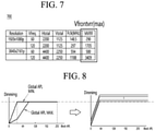
- FIG. 7 is a diagram for describing a table showing a correspondence relationship between a resolution, the number of lines during a maximum vertical front porch duration, and a scan rate according to an embodiment of the present disclosure.
- a table 700 which shows a correspondence relationship between a resolution, a vertical frequency (corresponding to a scan rate), a horizontal total porch (Htotal), a vertical total porch (Vtotal), a clock frequency (Fclk), and a value of the maximum vertical front porch (number of lines).
- the table 700 may be stored in a memory 170.
- the table 700 may define a value of MVRR corresponding to a supported representative resolution.
- the maximum vertical front porch MVRR may be a maximum value of the vertical front porch 520.
- Equation 1 CEILING f PixelClock / Htotal ⁇ VRR MIN ⁇ 0.994 ⁇ Vtotal ⁇ FVA_Factor
- the processor 111 may receive a resolution of an image frame from an external device through the external input interface 110.
- the processor 111 may determine a scan rate of the image frame using a value (number of lines) of the vertical front porch 520 obtained in step S301 and the table 700.
- a scan signal may be scanned in an area of 2200 X 1125, and when a resolution is 3840 X 2160, a scan signal may be scanned in an area of 4400 X 2250.
- the resolution may be information contained in a vertical back porch.
- the processor 111 may search for a vertical frequency matching the calculated number of lines from the table 700.
- the processor 111 may determine the scan rate of an image frame to be 60 Hz.
- the processor 111 may determine the scan rate of an image frame to be 120 Hz.
- the processor 111 may determine the scan rate of the image frame to be 60 Hz.
- the processor 111 may determine the scan rate of the image frame to be 120 Hz.
- the processor 111 of the display device 100 may determine whether the predicted scan rate of the image frame is different from a scan rate of a previous image frame (S203).
- the external device may change and output a frequency of the image frame in real time under a game mode.
- a screen tearing phenomenon may occur.
- the tearing is a phenomenon in which multiple frames overlap each other in single scan because synchronization is not performed when a frame rate of a graphic card exceeds the scan rate of a display panel.
- variable scan rate (VRR) method which performs synchronization such that the scan rate of the display panel is synchronized with the change in a frame rate of a graphic card may be used.
- a frequency of the image frame may be changed in real time.
- the processor 111 may store a scan rate of an image frame, which is previously input, in the memory 170.
- the processor 111 may determine whether the scan rate of the previously input image frame is equal to the predicted scan rate of the image frame.
- the processor 111 of the display device 100 may control the backlight unit 200 based on the changed scan rate of the image frame when the predicted scan rate of the image frame is different from the scan rate of the previous image frame (S207).
- the local dimming method may be a method for dividing a display screen of a liquid crystal display panel according to virtual blocks divided in a matrix form, deriving a representative value of input image data for each block, adjusting a dimming intensity (dimming value) for each block according to a representative value for each block and controlling a brightness of light sources of the backlight unit for each block.
- the processor 111 may determine a dimming intensity of the backlight unit 200 corresponding to the changed scan rate of the image frame, and may control the backlight unit 200 to output light with the determined dimming intensity.
- the dimming intensity may be the intensity of light output from each of the plurality of blocks constituting the backlight unit 200.
- the dimming intensity of each block may be adjusted differently.
- the backlight unit 200 may output light to have the dimming intensity determined according to a received control signal.
- the processor 111 may transmit a driving signal for outputting a dimming value determined according to the frequency of the image frame to the LED driving circuit 230 of the backlight unit 200.
- the LED driving circuit 230 may control the operation of the lamp unit 210 according to the received driving signal.
- a backlight block value (a dimming value of the backlight block) may be calculated according to [Equation 2].
- Weighted sum Backlight block value Block value by previous L / D + Vfrontvrr / Vfrontvrr max ? / BL max ? ⁇ BL setting )
- a block value according to an existing L/D may indicate a dimming value of a block during existing local dimming.
- Vfrontvrr may be a calculated value of the vertical front porch 520.
- Vfrontvrr(max) may be a value of the maximum vertical front porch corresponding to the resolution and Vfontvrr shown in the table 700 of FIG. 7 .
- BL (setting) may be a set dimming value of the backlight unit, and may be a settable value based on 8 bits (0 to 255).
- BL(max) may be the maximum dimming value of the backlight unit, and may be expressed as a value of 255 based on 8 bits.
- the backlight block value may be calculated according to [Equation 2].
- 253 may be expressed as 99.2% based on 8 bits.
- Vfrontvrr(max) may be obtained through the table 700 shown in FIG. 7 by the resolution and calculated Vfrontvrr.
- the backlight block value according to [Equation 2] may be a value to which luminance compensation is applied according to the calculated Vfrontvrr.
- the backlight block value according to [Equation 2] may be an equation used to prevent an abrupt change in the luminance value.
- a method of controlling a dimming value through conventional PWM and a method of controlling a dimming value of a block of the backlight unit 200 by Vfrontvrr, which is an embodiment of the present disclosure, are compared as follows.
- the PWM control method is a method of controlling the overall brightness of a screen by adjusting a current supplied to the backlight unit 200 through a PWM signal. Since the PWM method is linked to the user interface screen, real-time control linked to an input image frame is impossible.
- the luminance factor of the backlight unit according to the conventional PWM method is 90.25%, which is the product of the PWM setting value (95%) and the local dimming value (95%).
- the luminance factor of the backlight unit according to an embodiment of the present disclosure is 94.05%, which is the product of the PWM setting value (95%) and the local dimming value (99.2%) calculated by [Equation 2].
- the luminance when the frequency of the image frame falls to a low frequency, the luminance may be better compensated.
- the local dimming value and the block value may be used as having the same meaning.
- FIG. 8 is a graph for comparing dimming value control according to a conventional PWM method and dimming value control according to an embodiment of the present disclosure.
- the left graph is a graph showing a change in a dimming value according to the conventional PWM method
- the right graph is a graph showing a process in which a dimming value is adjusted according to a value of a vertical front porch according to an embodiment of the present disclosure.
- the horizontal axis of each of the left and right graphs represents the average picture level (APL) value of the block of the backlight unit, and the vertical axis represents the dimming value (dimming intensity).
- APL average picture level
- a dimming value may be adjusted according to the scan rate of the image frame.
- the present disclosure described above may be embodied as computer readable codes on a medium in which a program is recorded.
- the computer-readable medium includes all kinds of recording devices in which data readable by a computer system is stored. Examples of the computer readable medium may include a hard disk drive (HDD), a solid state disk (SSD), a silicon disk drive (SDD), a ROM, a RAM, a CD-ROM, a magnetic tape, a floppy disk, an optical data storage device, and the like.
- the computer may include a processor 170 of the display device 100.
Landscapes
- Engineering & Computer Science (AREA)
- Physics & Mathematics (AREA)
- Computer Hardware Design (AREA)
- General Physics & Mathematics (AREA)
- Theoretical Computer Science (AREA)
- Chemical & Material Sciences (AREA)
- Crystallography & Structural Chemistry (AREA)
- Control Of Indicators Other Than Cathode Ray Tubes (AREA)
- Liquid Crystal Display Device Control (AREA)
- Electrophonic Musical Instruments (AREA)
Abstract
A display device according to an embodiment of the present disclosure includes a display panel, a backlight unit configured to provide light to the display panel, an external input interface configured to receive an image frame from an external frame, and a processor configured to determine a scan rate of the image frame received through the external input interface, determine whether the determined scan rate is equal to a scan rate of a previous image frame, and control a dimming value of the backlight unit based on the determined scan rate of the image frame, when the determined scan rate is different from the scan rate of the previous image frame.
Description
- The present disclosure relates to a display device and a method of operating the same, and more particularly, to a display device for controlling luminance of a display panel and a method of operating the same.
- A display device for reproducing a game video may display more scenes during the same period of time than a display device operating at a scan rate of 60 Hz.
- A user may feel a much smoother screen as the refresh rate is higher, and in a game that requires a fast reaction speed, a higher scan rate is required.
- In addition, when the game video is played, a tearing phenomenon in which the screen is sheared horizontally may occur. The tearing phenomenon occurs when an image frame output by a graphic card and an image frame output by a display panel are not synchronized in a case where the scan rates of images are fixed.
- In order to prevent the tearing phenomenon, there has proposed a variable scan rate (or variable refresh rate, VRR) technology that synchronizes the output frequency of the image frame of the graphic card with the scan rate of the display panel.
- However, when a variable scan rate is applied, when an image signal with a low frequency is input, the charging and holding characteristics of pixel data deteriorate according to the storage capacitance size of the pixel electrode constituting the display panel, resulting in reduction in luminance.
- As a result, a change in luminance occurs largely, which is noticeable in the form of flicker, thus interfering with the user's viewing.
- In addition, a conventional liquid crystal display device controls the overall brightness of a screen through a pulse width modulation (PWM) signal, and controls backlight units with local dimming operation through serial peripheral interface (SPI) communication.
- Since the frequency of an input image frame is random even when a luminance compensation algorithm is applied through PWM control, the frequency of the image frame cannot be predicted, and thus PWM generation and control for luminance compensation is delayed during several frames.
- This causes a sudden change in luminance due to a delay in applying a luminance compensation value according to the frequency variable range of an input image frame, resulting in a phenomenon in which flickering becomes more severe.
- An object of the present disclosure is to prevent flickering by reducing a change in luminance according to a change in an image frequency during a variable refresh rate (VRR) operation.
- Another object of the present disclosure is to prevent flickering by reducing a change in luminance according to a change in an image frequency during a variable refresh rate (VRR) operation in an HDMI game mode.
- A display device according to an embodiment of the present disclosure may determines a scan rate of the image frame received through the external input interface, determine whether the determined scan rate is equal to a scan rate of a previous image frame, and when the determined scan rate is different from the scan rate of the previous image frame, and control a dimming value of the backlight unit based on the determined scan rate of the image frame.
- The display device may calculate a value of a vertical front porch constituting the image frame and determine a scan rate of the image frame using the calculated value of the vertical front porch.
- The display device may further include a memory configured to store a table showing a correspondence relationship between a resolution, a maximum vertical front porch value and a scan rate, and the display device may determine a scan rate of the image frame matching the calculated value of the vertical front porch using the table.
- The image frame may include information on the resolution, and the display device may determine a scan rate of the image frame matching the resolution and the maximum vertical front porch value greater than or equal to the calculated value of the vertical front porch.
- According to the present disclosure, it is possible to minimize a change in luminance according to a change in a scan rate of an image frame when a variable refresh rate (VRR) operation is performed, thereby minimizing the occurrence of flickering.
- According to the present disclosure, occurrence of flickering is suppressed when playing a game video, thereby enabling a user to watch a natural game video.
-
-
FIG. 1 is a block diagram for describing a configuration of a display device according to an embodiment of the present disclosure. -
FIG. 2 is a flowchart for describing a method of controlling luminance of a display device according to an embodiment of the present disclosure. -
FIG. 3 is a flowchart for describing a method of predicting a scan rate of an image frame according to an embodiment of the present disclosure. -
FIG. 4 is a diagram for describing the structure of an image data packet to which a variable scan rate is not applied,FIG. 5 is a diagram for describing the structure of an image data packet to which a variable scan rate is applied, andFIG. 6 is a diagram for describing the concept of a display panel having a resolution of 640X 480. -
FIG. 7 is a diagram for describing a table showing a correspondence relationship between a resolution, the number of lines during a maximum vertical front porch duration, and a scan rate according to an embodiment of the present disclosure. -
FIG. 8 is a graph for comparing dimming value control according to a conventional PWM method and dimming value control according to an embodiment of the present disclosure. - Hereinafter, embodiments of the present disclosure will be described in more detail with reference to the drawings.
-
FIG. 1 is a diagram illustrating a display device according to an embodiment of the present disclosure. - The
display device 100 ofFIG. 1 may be any one of a monitor, a TV, a tablet PC, and a mobile terminal. - The
display device 100 may include anexternal input interface 110, aprocessor 111, adisplay panel 160, and abacklight unit 200. - The
external input interface 110 may receive image data from an external device. - The
external input interface 110 may include one or more HDMI terminals and one or more A/V terminals. - The
display panel 160 may be a liquid crystal display panel. - The
display panel 160 may display an image based on an image signal input from theexternal input interface 110. - The
display panel 160 may include a plurality of data lines DL1 to DLm and a plurality of gate lines GL1 to GLn which are intersected in a matrix form on a glass substrate, and a plurality of pixels corresponding to intersections. - Each of the plurality of pixels may output an image based on an image signal provided from a
source driver 150, a driving signal provided to agate driver 140, and light provided from thebacklight unit 200. - The
memory 170 may store programs and information necessary for driving thedisplay panel 160. - The
backlight unit 200 may provide light to thedisplay panel 160. - The
external input interface 110 may receive a control signal including one or more of image data (RGB Data), a clock signal, a horizontal synchronization signal, a vertical synchronization signal, and a data enable signal from an external device. - The horizontal synchronization signal may be a signal for performing synchronization in the horizontal direction of a screen.
- The vertical synchronization signal may be a signal for performing synchronization in the vertical direction of the screen.
- Also, the data enable signal may indicate a period of supplying data to a pixel.
- The
external input interface 110 may be included in theprocessor 111. - The
processor 111 may include atiming controller 120, apower voltage generator 130, agate driver 140, and asource driver 150. - The
timing controller 120 may generate driving signals for driving thegate driver 140 including a plurality of driver integrated circuits and thesource driver 150 including a plurality of driver integrated circuits, by using a control signal received from theexternal input interface 110. - For example, a driving signal for driving the
gate driver 140 may include a high signal, a gate low signal, a clock signal, a start signal, a reset signal, and the like. - The
power voltage generator 130 may supply a power voltage, a reference voltage, a ground voltage, and the like necessary for the operation of each component included in theprocessor 111. - The
power voltage generator 130 may supply a common voltage corresponding to the reference voltage to thedisplay panel 160. - The
power voltage generator 130 may supply DC power (LED B+) required for driving thebacklight unit 200. - The
gate driver 140 may perform on/off control of each of the plurality of pixels included in thedisplay panel 160, in response to a driving signal input from thetiming controller 120. - The
gate driver 140 may sequentially enable the gate lines GL1 to GLn on thedisplay panel 160 for one horizontal synchronization time by outputting gate driving signals Vg1 to Vgn. - Accordingly, image signals supplied from the
source driver 150 may be applied to each pixel. - The
source driver 150 may apply an image signal to each pixel in response to a data signal and a driving signal input from thetiming controller 120. - The
backlight unit 200 may be arranged on one surface of thedisplay panel 160 to provide light to thedisplay panel 160. - The
backlight unit 200 may include alamp unit 210 and anLED driving circuit 230. - The
lamp unit 210 may provide light to thedisplay panel 160. - The
lamp unit 210 may provide light to thedisplay panel 160 such that thedisplay panel 160 implements a high dynamic range (HDR) image under the control of theLED driving circuit 230. - For this, a local dimming method may be used. The local dimming may be a method of turning on or off a light in a specific area of the screen.
- The local dimming may be used to implement an HDR image.
- The
lamp unit 210 may include a plurality of channels. Each of the channels may include one or more LED elements connected in series, a dimming circuit and a resistor. - Each LED element may emit red, green, or blue monochromatic light, or may emit white light.
- The dimming circuit may be a semiconductor switch capable of turning on or off one or more LED elements.
- The dimming circuit may be composed of field effect transistors (FETs).
- The resistor may be used to measure a current flowing through one channel. A DC voltage supplied from the
power voltage generator 130 to thelamp unit 210 may be dropped by passing through one or more LED elements, and the dropped voltage may be applied to the resistor. - By measuring a voltage across the resistor, a current flowing through the channel may be measured.
- The plurality of channels may be connected in parallel and may be electrically connected to the
LED driving circuit 230. - The
LED driving circuit 230 may control the operation of thelamp unit 210. - The
LED driving circuit 230 may include a plurality of LED drivers. - The number of LED drivers included in the
LED driving circuit 230 may be less than the number of channels included in thelamp unit 210. - The number of LED drivers may be equal to the number of dimming circuits. That is, the number of dimming circuits may also be less than the number of channels.
-
FIG. 2 is a flowchart for describing a method for controlling luminance of a display device according to an embodiment of the present disclosure. - Hereinafter, a frequency may mean a scan rate of an image frame.
- Referring to
FIG. 2 , theprocessor 111 of thedisplay device 100 may predict a scan rate of an image frame (S201). - The
external input interface 110 may receive an image signal or an image frame from a connected external device. - The external input interface may include one or more HDMI (High Definition Multimedia Interface) terminals or one or more A/V terminals.
- An external device connected to the
external input interface 110 may change a frequency and output an image frame. That is, theexternal input interface 110 may receive an image frame whose frequency varies over time. - The external device may transmit the image frame to the
display device 100 after including information indicating that a variable scan rate is applied to the image frame in the image frame. - In an embodiment, the
processor 111 may predict the scan rate of the image frame based on an image data packet received through theexternal input interface 110. - Details will be described with reference to
FIG. 3 . -
FIG. 3 is a flowchart for describing a method of predicting a scan rate of an image frame according to an embodiment of the present disclosure. - The
processor 111 of thedisplay device 100 may calculate the number of lines based on the image data packet received from the external input interface 110 (S301). - When a variable scan rate is applied, the image data packet may include information indicating a change in the scan rate.
- Details will be described with reference to the drawings below.
-
FIG. 4 is a diagram for describing the structure of an image data packet to which a variable scan rate is not applied,FIG. 5 is a diagram for describing the structure of an image data packet to which a variable scan rate is applied, andFIG. 6 is a diagram for describing the concept of a display panel having a resolution of 640X 480. - First, referring to
FIG. 4 , a first verticalimage data packet 400 may include a verticalactive porch 410, a verticalfront porch 420, avertical sync porch 430, and avertical back porch 440. - The first
image data packet 400 ofFIG. 4 may have the structure of an image data packet to which a variable scan rate is not applied. - The vertical
active porch 410 may be a section including data on an actual image to be displayed on a screen. - The
front porch 420 may be a section indicating a waiting time after output of a vertical signal. The vertical signal may be a signal corresponding to the verticalactive porch 410. - The
vertical sync porch 430 may be a section for synchronizing vertical signals. - The
vertical back porch 440 may be a section indicating a vertical signal output waiting time for which waiting is performed until the next vertical signal is output. - The sum of the vertical
front porch 420, thevertical sync porch 430, and thevertical back porch 440 may be referred to as a vertical blank porch. - That is, the first
image data packet 400 may be the sum of the vertical active porch and the vertical blank porch. - When the variable scan rate is not applied, the section of the vertical
front porch 420 of the firstimage data packet 400 may be fixed. - Next, the structure of the second
image data packet 500 to which the variable scan rate is applied will be described. - The second vertical
image data packet 500 may include a verticalactive porch 510, a verticalfront porch 520, avertical sync porch 530, and avertical back porch 540. - The sum of the vertical
front porch 520, thevertical sync porch 530, and thevertical back porch 540 may be referred to as a vertical blank porch. - That is, the first
image data packet 500 may be the sum of the vertical active porch and the vertical blank porch. - The vertical
active porch 510 may be a section including data on an actual image to be displayed on a screen. - The
front porch 520 may be a section indicating a waiting time after output of a vertical signal. The vertical signal may be a signal corresponding to the verticalactive porch 510. - The
vertical sync porch 530 may be a section for synchronizing vertical signals. - The
vertical back porch 540 may be a section indicating a vertical signal output waiting time for which waiting is performed until the next vertical signal is output. - Referring to
FIG. 6 , an area in which an actual image is displayed may correspond to 640X 480, and an area to which a scan signal is applied may correspond to 800 X 525. An area where an actual image is not displayed may be a porch portion. - When a variable scan rate is applied, the section of the vertical
front porch 520 of the secondimage data packet 500 may be changed. That is, the value of the verticalfront porch 520 of theimage data packet 500 input from theexternal input interface 110 may be changed in real time. - The value of the vertical
front porch 520 may be the number of lines of the horizontal synchronization signal input onto the verticalfront porch 520. - The
processor 111 may determine the scan rate of the secondimage data packet 500 based on a change in the verticalfront porch 520 of the secondimage data packet 500. - The
processor 111 may count the value of the verticalfront porch 520. To this end, theprocessor 111 may include a separate counter. - The
processor 111 may calculate a value of the verticalfront porch 520 and may determine a scan rate of an image frame based on the calculated number of lines. - The
processor 111 may count the verticalfront porch 520 and calculate a synchronization value based on the falling edge of the input horizontal synchronization signal and the vertical synchronization signal. - The
processor 111 may determine the scan rate of the secondimage data packet 500 based on a change in the vertical blank porch of the secondimage data packet 500. - Since the vertical blank porch is the sum of the vertical
front porch 520, thevertical sync porch 530, and thevertical back porch 540, the vertical blank porch may be changed according to a change in the verticalfront porch 520 when thevertical sync porch 530 and thevertical back porch 540 are fixed. - The
processor 111 may determine the scan rate of the secondimage data packet 500 using a value of the vertical blank porch of the secondimage data packet 500. - The
processor 111 of thedisplay device 100 may determine a scan rate of an image frame using the calculated number of lines (S303). - The
processor 111 may determine a scan rate of an image frame based on a table showing a correspondence relationship between the number of lines and the scan rate of the verticalblank porch 520. - Details will be described with reference to
FIG. 7 . -
FIG. 7 is a diagram for describing a table showing a correspondence relationship between a resolution, the number of lines during a maximum vertical front porch duration, and a scan rate according to an embodiment of the present disclosure. - Referring to
FIG. 7 , a table 700 is shown, which shows a correspondence relationship between a resolution, a vertical frequency (corresponding to a scan rate), a horizontal total porch (Htotal), a vertical total porch (Vtotal), a clock frequency (Fclk), and a value of the maximum vertical front porch (number of lines). - The table 700 may be stored in a
memory 170. - The table 700 may define a value of MVRR corresponding to a supported representative resolution.
- The maximum vertical front porch MVRR may be a maximum value of the vertical
front porch 520. - The value of the maximum vertical front porch MVRR may be calculated through Equation 1 below.

- The
processor 111 may receive a resolution of an image frame from an external device through theexternal input interface 110. - The
processor 111 may determine a scan rate of the image frame using a value (number of lines) of the verticalfront porch 520 obtained in step S301 and the table 700. - When a resolution is 1920 X 1080, a scan signal may be scanned in an area of 2200
X 1125, and when a resolution is 3840 X 2160, a scan signal may be scanned in an area of 4400X 2250. - The resolution may be information contained in a vertical back porch.
- When the number of lines of the resolution vertical
front porch 520 obtained from an external device is calculated, theprocessor 111 may search for a vertical frequency matching the calculated number of lines from the table 700. - For example, when the resolution is 1920 X 1080 and the number of lines of the vertical front porch is 290 or less, the
processor 111 may determine the scan rate of an image frame to be 60 Hz. - In addition, when the resolution is 1920 X 1080 and the number of lines of the vertical front porch is 290 or less, the
processor 111 may determine the scan rate of an image frame to be 120 Hz. - In addition, when the resolution is 3840 X 2160 and the number of lines of the vertical front porch is 580 or less, the
processor 111 may determine the scan rate of the image frame to be 60 Hz. - In addition, when the resolution is 3840 X 2160 and the number of lines of the vertical front porch is 580 or less, the
processor 111 may determine the scan rate of the image frame to be 120 Hz. - As described above, according to an embodiment of the present disclosure, it is possible to predict a scan rate of an image frame by calculating the number of lines of the vertical front porch.
- A description will be given referring again to
FIG. 2 . - The
processor 111 of thedisplay device 100 may determine whether the predicted scan rate of the image frame is different from a scan rate of a previous image frame (S203). - The external device may change and output a frequency of the image frame in real time under a game mode.
- In the case of a game image in which a fast screen switching is performed, a screen tearing phenomenon may occur. The tearing is a phenomenon in which multiple frames overlap each other in single scan because synchronization is not performed when a frame rate of a graphic card exceeds the scan rate of a display panel.
- In order to prevent tearing, a variable scan rate (VRR) method which performs synchronization such that the scan rate of the display panel is synchronized with the change in a frame rate of a graphic card may be used.
- Due to the variable scan rate method, a frequency of the image frame may be changed in real time.
- The
processor 111 may store a scan rate of an image frame, which is previously input, in thememory 170. - The
processor 111 may determine whether the scan rate of the previously input image frame is equal to the predicted scan rate of the image frame. - The
processor 111 of thedisplay device 100 may control thebacklight unit 200 based on the changed scan rate of the image frame when the predicted scan rate of the image frame is different from the scan rate of the previous image frame (S207). - The local dimming method may be a method for dividing a display screen of a liquid crystal display panel according to virtual blocks divided in a matrix form, deriving a representative value of input image data for each block, adjusting a dimming intensity (dimming value) for each block according to a representative value for each block and controlling a brightness of light sources of the backlight unit for each block.
- The
processor 111 may determine a dimming intensity of thebacklight unit 200 corresponding to the changed scan rate of the image frame, and may control thebacklight unit 200 to output light with the determined dimming intensity. - The dimming intensity may be the intensity of light output from each of the plurality of blocks constituting the
backlight unit 200. - When the
backline unit 200 includes a plurality of blocks, the dimming intensity of each block may be adjusted differently. - The
backlight unit 200 may output light to have the dimming intensity determined according to a received control signal. - The
processor 111 may transmit a driving signal for outputting a dimming value determined according to the frequency of the image frame to theLED driving circuit 230 of thebacklight unit 200. - The
LED driving circuit 230 may control the operation of thelamp unit 210 according to the received driving signal. - A backlight block value (a dimming value of the backlight block) may be calculated according to [Equation 2].

- A block value according to an existing L/D may indicate a dimming value of a block during existing local dimming.
- Vfrontvrr may be a calculated value of the vertical
front porch 520. - Vfrontvrr(max) may be a value of the maximum vertical front porch corresponding to the resolution and Vfontvrr shown in the table 700 of
FIG. 7 . - BL (setting) may be a set dimming value of the backlight unit, and may be a settable value based on 8 bits (0 to 255).
- BL(max) may be the maximum dimming value of the backlight unit, and may be expressed as a value of 255 based on 8 bits.
- For example, in a state where the resolution is 1920 X 1080 and the scan rate of the image frame is 120Hz, when the calculated value of Vfrontvrr is 1421 and the value of the BL (setting) is 95% (243), the backlight block value may be calculated according to [Equation 2].
- It may be calculated as the backlight block value = 243+(1421/(1705/(255-243)))=243+10=253. 253 may be expressed as 99.2% based on 8 bits.
- Vfrontvrr(max) may be obtained through the table 700 shown in
FIG. 7 by the resolution and calculated Vfrontvrr. - The backlight block value according to [Equation 2] may be a value to which luminance compensation is applied according to the calculated Vfrontvrr.
- The backlight block value according to [Equation 2] may be an equation used to prevent an abrupt change in the luminance value.
- A method of controlling a dimming value through conventional PWM and a method of controlling a dimming value of a block of the
backlight unit 200 by Vfrontvrr, which is an embodiment of the present disclosure, are compared as follows. - The PWM control method is a method of controlling the overall brightness of a screen by adjusting a current supplied to the
backlight unit 200 through a PWM signal. Since the PWM method is linked to the user interface screen, real-time control linked to an input image frame is impossible. - The luminance factor of the backlight unit according to the conventional PWM method is 90.25%, which is the product of the PWM setting value (95%) and the local dimming value (95%).
- The luminance factor of the backlight unit according to an embodiment of the present disclosure is 94.05%, which is the product of the PWM setting value (95%) and the local dimming value (99.2%) calculated by [Equation 2].
- That is, compared with the conventional PWM method, when the frequency of the image frame falls to a low frequency, the luminance may be better compensated.
- Accordingly, even during the VRR operation, a sharp change in luminance is not made, thus preventing the flickering phenomenon.
- Meanwhile, in the present disclosure, the local dimming value and the block value may be used as having the same meaning.
-
FIG. 8 is a graph for comparing dimming value control according to a conventional PWM method and dimming value control according to an embodiment of the present disclosure. - In
FIG. 8 , the left graph is a graph showing a change in a dimming value according to the conventional PWM method, and the right graph is a graph showing a process in which a dimming value is adjusted according to a value of a vertical front porch according to an embodiment of the present disclosure. - The horizontal axis of each of the left and right graphs represents the average picture level (APL) value of the block of the backlight unit, and the vertical axis represents the dimming value (dimming intensity).
- In the case of the conventional PWM method, even when the scan rate of an image frame is changed, there is no change in the dimming value after a certain APL value.
- However, according to an embodiment of the present disclosure, a dimming value may be adjusted according to the scan rate of the image frame.
- When the dimming value is adjusted according to the scan rate of the image frame, a sudden change in luminance may be prevented. Accordingly, there is an effect that the flickering phenomenon is greatly prevented.
- The present disclosure described above may be embodied as computer readable codes on a medium in which a program is recorded. The computer-readable medium includes all kinds of recording devices in which data readable by a computer system is stored. Examples of the computer readable medium may include a hard disk drive (HDD), a solid state disk (SSD), a silicon disk drive (SDD), a ROM, a RAM, a CD-ROM, a magnetic tape, a floppy disk, an optical data storage device, and the like. In addition, the computer may include a
processor 170 of thedisplay device 100.
Claims (15)
- A display device (100) comprising:a display panel (160);a backlight unit (200) configured to provide light to the display panel;an external input interface (110) configured to receive an image frame from an external frame; anda processor configured to:determine a scan rate of the image frame received through the external input interface,determine whether the determined scan rate is equal to a scan rate of a previous image frame, and control a dimming value of the backlight unit based on the determined scan rate of the image frame, when the determined scan rate is different from the scan rate of the previous image frame.
- The display device (100) of claim 1, wherein the processor is configured to calculate a value of a vertical front porch constituting the image frame and determine a scan rate of the image frame using the calculated value of the vertical front porch.
- The display device (100) of claim 2, further comprising:a memory (170) configured to store a table showing a correspondence relationship between a resolution, a maximum vertical front porch value and a scan rate, andwherein the processor is configured to determine a scan rate of the image frame matching the calculated value of the vertical front porch using the table.
- The display device (100) of claim 3, wherein the image frame includes information on the resolution,
wherein the processor is configured to determine a scan rate of the image frame matching the resolution and the maximum vertical front porch value greater than or equal to the calculated value of the vertical front porch. - The display device (100) of claim 1, wherein the image frame includes a vertical active porch and a vertical blank porch representing displayed image data,
wherein the vertical blank porch includes a vertical front porch, a vertical sync porch and a vertical back porch, and
wherein the processor is configured to determine a scan rate of the image frame using the value of the vertical blank porch. - The display device (100) of any one of claims 2 to 5, wherein the value of the vertical front porch is a number of lines of a horizontal synchronization signal input onto the vertical front porch.
- The display device (100) of claim 4, wherein the processor is configured to determine the dimming value based on the value of the vertical front porch, the maximum vertical front porch value, and the scan rate of the image frame.
- The display device (100) of any one of claims 1 to 7, wherein the backlight unit includes:a lamp unit including a plurality of blocks, each of the blocks including a plurality of LEDs, anda LED driving circuit configured to control driving of the lamp unit.
- A method for operating a display device (100) comprising:receiving an image frame from an external frame;determining a scan rate of the image frame received through the external input interface;determining whether the determined scan rate is equal to a scan rate of a previous image frame; andcontrolling a dimming value of the backlight unit based on the determined scan rate of the image frame when the determined scan rate is different from the scan rate of the previous image frame.
- The method of claim 9, wherein the determining of the scan rate includes
calculating a value of a vertical front porch constituting the image frame; and
determining a scan rate of the image frame using the calculated value of the vertical front porch. - The method of claim 10, further comprising:storing a table showing a correspondence relationship between a resolution, a maximum vertical front porch value and a scan rate.wherein the determining of the scan rate includes determining a scan rate of the image frame matching the calculated value of the vertical front porch using the table.
- The method of claim 11, wherein the image frame includes information on the resolution, and
wherein the determining of the scan rate includes determining a scan rate of the image frame matching the resolution and the maximum vertical front porch value greater than or equal to the calculated value of the vertical front porch. - The method of any one of claims 9 to 12, wherein the image frame includes a vertical active porch and a vertical blank porch representing displayed image data,
wherein the vertical blank porch includes a vertical front porch, a vertical sync porch and a vertical back porch, and
wherein the determining of the scan rate includes determining a scan rate of the image frame using the value of the vertical blank porch. - The method of any one of claims 10 to 13, wherein the value of the vertical front porch is a number of lines of a horizontal synchronization signal input onto the vertical front porch.
- The method of any one of claims 12 to 14, wherein the determining of the dimming value includes determining the dimming value based on the value of the vertical front porch, the maximum vertical front porch value, and the scan rate of the image frame,
wherein the backlight unit includes
a lamp unit including a plurality of blocks, each of the blocks including a plurality of LEDs, and
a LED driving circuit configured to control driving of the lamp unit.
Applications Claiming Priority (1)
| Application Number | Priority Date | Filing Date | Title |
|---|---|---|---|
| KR1020200117945A KR102442662B1 (en) | 2020-09-14 | 2020-09-14 | Display device and operating method thereof |
Publications (1)
| Publication Number | Publication Date |
|---|---|
| EP3968318A1 true EP3968318A1 (en) | 2022-03-16 |
Family
ID=73598731
Family Applications (1)
| Application Number | Title | Priority Date | Filing Date |
|---|---|---|---|
| EP20210003.8A Pending EP3968318A1 (en) | 2020-09-14 | 2020-11-26 | Display device and method of operating the same |
Country Status (3)
| Country | Link |
|---|---|
| US (1) | US11205400B1 (en) |
| EP (1) | EP3968318A1 (en) |
| KR (1) | KR102442662B1 (en) |
Cited By (2)
| Publication number | Priority date | Publication date | Assignee | Title |
|---|---|---|---|---|
| TWI831517B (en) * | 2022-12-14 | 2024-02-01 | 瑞昱半導體股份有限公司 | Electronic device and associated image processing method |
| EP4550810A4 (en) * | 2022-07-21 | 2025-06-04 | Huawei Technologies Co., Ltd. | SIGNAL TRANSMISSION METHOD AND DEVICE |
Families Citing this family (8)
| Publication number | Priority date | Publication date | Assignee | Title |
|---|---|---|---|---|
| US11936927B2 (en) * | 2020-09-23 | 2024-03-19 | Realtek Semiconductor Corporation | Transmission control system of multi-media signal, transmitter control circuit and receiver control circuit |
| TWI779494B (en) * | 2021-02-18 | 2022-10-01 | 瑞昱半導體股份有限公司 | Control circuit and control method applied to display |
| CN116343661A (en) * | 2021-12-24 | 2023-06-27 | 北京小米移动软件有限公司 | Display control method and device |
| KR102702436B1 (en) * | 2022-04-26 | 2024-09-05 | 엘지전자 주식회사 | Display device and operating method thereof |
| EP4546319A4 (en) | 2022-09-30 | 2025-07-09 | Samsung Electronics Co Ltd | ELECTRONIC DEVICE AND METHOD FOR CONTROLLING A SIGNAL PROVIDED TO A PROCESSOR |
| KR20240092226A (en) * | 2022-12-13 | 2024-06-24 | 삼성디스플레이 주식회사 | Display device |
| CN115985223B (en) * | 2023-03-21 | 2023-08-25 | 惠科股份有限公司 | Display device and driving method thereof |
| KR20250082544A (en) | 2023-11-30 | 2025-06-09 | 엘지전자 주식회사 | Sink device and operating method thereof |
Citations (4)
| Publication number | Priority date | Publication date | Assignee | Title |
|---|---|---|---|---|
| US20170124934A1 (en) * | 2015-10-29 | 2017-05-04 | Nvidia Corporation | Variable refresh rate gamma correction |
| US20180277034A1 (en) * | 2017-03-27 | 2018-09-27 | Samsung Electronics Co., Ltd. | Display Driving Device |
| US20190221186A1 (en) * | 2018-01-17 | 2019-07-18 | Lg Electronics Inc. | Display device and image signal processing method of the same |
| US20200135146A1 (en) * | 2018-10-26 | 2020-04-30 | Samsung Display Co., Ltd. | Display device supporting variable frame mode, and method of operating display device |
Family Cites Families (9)
| Publication number | Priority date | Publication date | Assignee | Title |
|---|---|---|---|---|
| US5991883A (en) * | 1996-06-03 | 1999-11-23 | Compaq Computer Corporation | Power conservation method for a portable computer with LCD display |
| JP4488013B2 (en) * | 2007-03-08 | 2010-06-23 | 船井電機株式会社 | Digital image display device |
| TWI352317B (en) * | 2007-09-20 | 2011-11-11 | Nuvoton Technology Corp | Image processing methods and systems |
| KR20090069791A (en) * | 2007-12-26 | 2009-07-01 | 삼성전자주식회사 | Light source control device and method of display device |
| US9064449B2 (en) * | 2012-01-20 | 2015-06-23 | Sharp Laboratories Of America, Inc. | Electronic devices configured for adapting refresh behavior |
| US9036084B2 (en) * | 2013-04-11 | 2015-05-19 | Qualcomm Incorporated | Apparatus and method for synchronous display of video data |
| JP6524606B2 (en) * | 2014-03-25 | 2019-06-05 | セイコーエプソン株式会社 | Display control device and display device |
| KR102583828B1 (en) * | 2018-09-19 | 2023-10-04 | 삼성디스플레이 주식회사 | Liquid crystal display apparatus and method of driving the same |
| TWI731587B (en) * | 2020-02-17 | 2021-06-21 | 緯創資通股份有限公司 | Display control method and display apparatus |
-
2020
- 2020-09-14 KR KR1020200117945A patent/KR102442662B1/en active Active
- 2020-10-08 US US17/066,336 patent/US11205400B1/en active Active
- 2020-11-26 EP EP20210003.8A patent/EP3968318A1/en active Pending
Patent Citations (4)
| Publication number | Priority date | Publication date | Assignee | Title |
|---|---|---|---|---|
| US20170124934A1 (en) * | 2015-10-29 | 2017-05-04 | Nvidia Corporation | Variable refresh rate gamma correction |
| US20180277034A1 (en) * | 2017-03-27 | 2018-09-27 | Samsung Electronics Co., Ltd. | Display Driving Device |
| US20190221186A1 (en) * | 2018-01-17 | 2019-07-18 | Lg Electronics Inc. | Display device and image signal processing method of the same |
| US20200135146A1 (en) * | 2018-10-26 | 2020-04-30 | Samsung Display Co., Ltd. | Display device supporting variable frame mode, and method of operating display device |
Cited By (3)
| Publication number | Priority date | Publication date | Assignee | Title |
|---|---|---|---|---|
| EP4550810A4 (en) * | 2022-07-21 | 2025-06-04 | Huawei Technologies Co., Ltd. | SIGNAL TRANSMISSION METHOD AND DEVICE |
| TWI831517B (en) * | 2022-12-14 | 2024-02-01 | 瑞昱半導體股份有限公司 | Electronic device and associated image processing method |
| US12335506B2 (en) | 2022-12-14 | 2025-06-17 | Realtek Semiconductor Corp. | Electronic device and associated signal processing method |
Also Published As
| Publication number | Publication date |
|---|---|
| KR102442662B1 (en) | 2022-09-13 |
| KR20220035783A (en) | 2022-03-22 |
| US11205400B1 (en) | 2021-12-21 |
Similar Documents
| Publication | Publication Date | Title |
|---|---|---|
| US11205400B1 (en) | Display device for controlling luminance of a display panel and method of operating the same | |
| US12148397B2 (en) | Display device and operation method therefor | |
| US11763771B2 (en) | Sink device with variable frame rate and display device including the same | |
| US6977636B2 (en) | Liquid crystal display device driving method | |
| KR102583828B1 (en) | Liquid crystal display apparatus and method of driving the same | |
| US20080136752A1 (en) | Image Display Apparatus, Image Display Monitor and Television Receiver | |
| JP4602608B2 (en) | Display device | |
| KR20030073390A (en) | A liquid crystal display for improving dynamic contrast and a method for generating gamma voltages for the liquid crystal display | |
| US10311813B2 (en) | Control device, display device, control method, and storage medium | |
| US20100231814A1 (en) | Liquid crystal display device and its driving method | |
| KR20180049332A (en) | Display device capable of changing frame rate and driving method thereof | |
| JP2002251175A (en) | Time division liquid crystal display device and color image display method thereof | |
| CN114283750A (en) | Display device and display method thereof | |
| EP3648095A1 (en) | Display method and display system for reducing a double image effect | |
| US10360839B2 (en) | Apparatus and method of driving a variable rate display | |
| US10930194B2 (en) | Display method and display system for reducing image delay by adjusting an image data clock signal | |
| EP3799019B1 (en) | Display apparatus | |
| JP5280627B2 (en) | Liquid crystal display device and driving method thereof | |
| JP2003284088A (en) | Color sequential display method, display device and driving method thereof | |
| US11615753B2 (en) | Control circuit applied to display and associated control method | |
| JP2008197349A (en) | Electro-optical device, processing circuit, processing method and electronic equipment | |
| CN120690158A (en) | Display device and display panel | |
| US11756476B1 (en) | Display device and operating method thereof | |
| CN115841803B (en) | Driving control method, driving circuit, display device and display system | |
| US12512038B2 (en) | Display apparatus |
Legal Events
| Date | Code | Title | Description |
|---|---|---|---|
| PUAI | Public reference made under article 153(3) epc to a published international application that has entered the european phase |
Free format text: ORIGINAL CODE: 0009012 |
|
| STAA | Information on the status of an ep patent application or granted ep patent |
Free format text: STATUS: REQUEST FOR EXAMINATION WAS MADE |
|
| 17P | Request for examination filed |
Effective date: 20201226 |
|
| AK | Designated contracting states |
Kind code of ref document: A1 Designated state(s): AL AT BE BG CH CY CZ DE DK EE ES FI FR GB GR HR HU IE IS IT LI LT LU LV MC MK MT NL NO PL PT RO RS SE SI SK SM TR |
|
| STAA | Information on the status of an ep patent application or granted ep patent |
Free format text: STATUS: EXAMINATION IS IN PROGRESS |
|
| 17Q | First examination report despatched |
Effective date: 20221114 |