EP3967976A1 - A method for motion estimation in a vehicle, corresponding device and computer program product - Google Patents
A method for motion estimation in a vehicle, corresponding device and computer program product Download PDFInfo
- Publication number
- EP3967976A1 EP3967976A1 EP21306152.6A EP21306152A EP3967976A1 EP 3967976 A1 EP3967976 A1 EP 3967976A1 EP 21306152 A EP21306152 A EP 21306152A EP 3967976 A1 EP3967976 A1 EP 3967976A1
- Authority
- EP
- European Patent Office
- Prior art keywords
- dataset
- data
- frequency
- sub
- imd
- Prior art date
- Legal status (The legal status is an assumption and is not a legal conclusion. Google has not performed a legal analysis and makes no representation as to the accuracy of the status listed.)
- Granted
Links
Images





Classifications
-
- G—PHYSICS
- G01—MEASURING; TESTING
- G01C—MEASURING DISTANCES, LEVELS OR BEARINGS; SURVEYING; NAVIGATION; GYROSCOPIC INSTRUMENTS; PHOTOGRAMMETRY OR VIDEOGRAMMETRY
- G01C21/00—Navigation; Navigational instruments not provided for in groups G01C1/00 - G01C19/00
- G01C21/26—Navigation; Navigational instruments not provided for in groups G01C1/00 - G01C19/00 specially adapted for navigation in a road network
- G01C21/28—Navigation; Navigational instruments not provided for in groups G01C1/00 - G01C19/00 specially adapted for navigation in a road network with correlation of data from several navigational instruments
-
- B—PERFORMING OPERATIONS; TRANSPORTING
- B60—VEHICLES IN GENERAL
- B60W—CONJOINT CONTROL OF VEHICLE SUB-UNITS OF DIFFERENT TYPE OR DIFFERENT FUNCTION; CONTROL SYSTEMS SPECIALLY ADAPTED FOR HYBRID VEHICLES; ROAD VEHICLE DRIVE CONTROL SYSTEMS FOR PURPOSES NOT RELATED TO THE CONTROL OF A PARTICULAR SUB-UNIT
- B60W40/00—Estimation or calculation of non-directly measurable driving parameters for road vehicle drive control systems not related to the control of a particular sub unit, e.g. by using mathematical models
- B60W40/10—Estimation or calculation of non-directly measurable driving parameters for road vehicle drive control systems not related to the control of a particular sub unit, e.g. by using mathematical models related to vehicle motion
- B60W40/101—Side slip angle of tyre
-
- B—PERFORMING OPERATIONS; TRANSPORTING
- B60—VEHICLES IN GENERAL
- B60W—CONJOINT CONTROL OF VEHICLE SUB-UNITS OF DIFFERENT TYPE OR DIFFERENT FUNCTION; CONTROL SYSTEMS SPECIALLY ADAPTED FOR HYBRID VEHICLES; ROAD VEHICLE DRIVE CONTROL SYSTEMS FOR PURPOSES NOT RELATED TO THE CONTROL OF A PARTICULAR SUB-UNIT
- B60W40/00—Estimation or calculation of non-directly measurable driving parameters for road vehicle drive control systems not related to the control of a particular sub unit, e.g. by using mathematical models
- B60W40/10—Estimation or calculation of non-directly measurable driving parameters for road vehicle drive control systems not related to the control of a particular sub unit, e.g. by using mathematical models related to vehicle motion
- B60W40/11—Pitch movement
-
- B—PERFORMING OPERATIONS; TRANSPORTING
- B60—VEHICLES IN GENERAL
- B60W—CONJOINT CONTROL OF VEHICLE SUB-UNITS OF DIFFERENT TYPE OR DIFFERENT FUNCTION; CONTROL SYSTEMS SPECIALLY ADAPTED FOR HYBRID VEHICLES; ROAD VEHICLE DRIVE CONTROL SYSTEMS FOR PURPOSES NOT RELATED TO THE CONTROL OF A PARTICULAR SUB-UNIT
- B60W40/00—Estimation or calculation of non-directly measurable driving parameters for road vehicle drive control systems not related to the control of a particular sub unit, e.g. by using mathematical models
- B60W40/10—Estimation or calculation of non-directly measurable driving parameters for road vehicle drive control systems not related to the control of a particular sub unit, e.g. by using mathematical models related to vehicle motion
- B60W40/112—Roll movement
-
- B—PERFORMING OPERATIONS; TRANSPORTING
- B60—VEHICLES IN GENERAL
- B60W—CONJOINT CONTROL OF VEHICLE SUB-UNITS OF DIFFERENT TYPE OR DIFFERENT FUNCTION; CONTROL SYSTEMS SPECIALLY ADAPTED FOR HYBRID VEHICLES; ROAD VEHICLE DRIVE CONTROL SYSTEMS FOR PURPOSES NOT RELATED TO THE CONTROL OF A PARTICULAR SUB-UNIT
- B60W40/00—Estimation or calculation of non-directly measurable driving parameters for road vehicle drive control systems not related to the control of a particular sub unit, e.g. by using mathematical models
- B60W40/10—Estimation or calculation of non-directly measurable driving parameters for road vehicle drive control systems not related to the control of a particular sub unit, e.g. by using mathematical models related to vehicle motion
- B60W40/114—Yaw movement
-
- G—PHYSICS
- G01—MEASURING; TESTING
- G01C—MEASURING DISTANCES, LEVELS OR BEARINGS; SURVEYING; NAVIGATION; GYROSCOPIC INSTRUMENTS; PHOTOGRAMMETRY OR VIDEOGRAMMETRY
- G01C21/00—Navigation; Navigational instruments not provided for in groups G01C1/00 - G01C19/00
- G01C21/10—Navigation; Navigational instruments not provided for in groups G01C1/00 - G01C19/00 by using measurements of speed or acceleration
- G01C21/12—Navigation; Navigational instruments not provided for in groups G01C1/00 - G01C19/00 by using measurements of speed or acceleration executed aboard the object being navigated; Dead reckoning
- G01C21/16—Navigation; Navigational instruments not provided for in groups G01C1/00 - G01C19/00 by using measurements of speed or acceleration executed aboard the object being navigated; Dead reckoning by integrating acceleration or speed, i.e. inertial navigation
- G01C21/165—Navigation; Navigational instruments not provided for in groups G01C1/00 - G01C19/00 by using measurements of speed or acceleration executed aboard the object being navigated; Dead reckoning by integrating acceleration or speed, i.e. inertial navigation combined with non-inertial navigation instruments
-
- G—PHYSICS
- G01—MEASURING; TESTING
- G01S—RADIO DIRECTION-FINDING; RADIO NAVIGATION; DETERMINING DISTANCE OR VELOCITY BY USE OF RADIO WAVES; LOCATING OR PRESENCE-DETECTING BY USE OF THE REFLECTION OR RERADIATION OF RADIO WAVES; ANALOGOUS ARRANGEMENTS USING OTHER WAVES
- G01S19/00—Satellite radio beacon positioning systems; Determining position, velocity or attitude using signals transmitted by such systems
- G01S19/38—Determining a navigation solution using signals transmitted by a satellite radio beacon positioning system
- G01S19/39—Determining a navigation solution using signals transmitted by a satellite radio beacon positioning system the satellite radio beacon positioning system transmitting time-stamped messages, e.g. GPS [Global Positioning System], GLONASS [Global Orbiting Navigation Satellite System] or GALILEO
- G01S19/42—Determining position
- G01S19/45—Determining position by combining measurements of signals from the satellite radio beacon positioning system with a supplementary measurement
- G01S19/47—Determining position by combining measurements of signals from the satellite radio beacon positioning system with a supplementary measurement the supplementary measurement being an inertial measurement, e.g. tightly coupled inertial
-
- B—PERFORMING OPERATIONS; TRANSPORTING
- B60—VEHICLES IN GENERAL
- B60W—CONJOINT CONTROL OF VEHICLE SUB-UNITS OF DIFFERENT TYPE OR DIFFERENT FUNCTION; CONTROL SYSTEMS SPECIALLY ADAPTED FOR HYBRID VEHICLES; ROAD VEHICLE DRIVE CONTROL SYSTEMS FOR PURPOSES NOT RELATED TO THE CONTROL OF A PARTICULAR SUB-UNIT
- B60W2520/00—Input parameters relating to overall vehicle dynamics
- B60W2520/28—Wheel speed
-
- G—PHYSICS
- G01—MEASURING; TESTING
- G01S—RADIO DIRECTION-FINDING; RADIO NAVIGATION; DETERMINING DISTANCE OR VELOCITY BY USE OF RADIO WAVES; LOCATING OR PRESENCE-DETECTING BY USE OF THE REFLECTION OR RERADIATION OF RADIO WAVES; ANALOGOUS ARRANGEMENTS USING OTHER WAVES
- G01S19/00—Satellite radio beacon positioning systems; Determining position, velocity or attitude using signals transmitted by such systems
- G01S19/38—Determining a navigation solution using signals transmitted by a satellite radio beacon positioning system
- G01S19/39—Determining a navigation solution using signals transmitted by a satellite radio beacon positioning system the satellite radio beacon positioning system transmitting time-stamped messages, e.g. GPS [Global Positioning System], GLONASS [Global Orbiting Navigation Satellite System] or GALILEO
- G01S19/52—Determining velocity
-
- G—PHYSICS
- G01—MEASURING; TESTING
- G01S—RADIO DIRECTION-FINDING; RADIO NAVIGATION; DETERMINING DISTANCE OR VELOCITY BY USE OF RADIO WAVES; LOCATING OR PRESENCE-DETECTING BY USE OF THE REFLECTION OR RERADIATION OF RADIO WAVES; ANALOGOUS ARRANGEMENTS USING OTHER WAVES
- G01S19/00—Satellite radio beacon positioning systems; Determining position, velocity or attitude using signals transmitted by such systems
- G01S19/38—Determining a navigation solution using signals transmitted by a satellite radio beacon positioning system
- G01S19/39—Determining a navigation solution using signals transmitted by a satellite radio beacon positioning system the satellite radio beacon positioning system transmitting time-stamped messages, e.g. GPS [Global Positioning System], GLONASS [Global Orbiting Navigation Satellite System] or GALILEO
- G01S19/53—Determining attitude
Definitions
- the description relates to the field of navigation, i.e. the capability of a device to determine a user position, velocity (speed) and attitude (i.e. 3D direction).
- One or more embodiments may refer to techniques for providing navigation information, for instance in a land vehicle, including position and attitude information.
- GNSS Global Navigation Satellite System
- a GNSS receiver While capable of providing an absolute position reference, a GNSS receiver may possibly exhibit various drawbacks: for instance, it relies on a satellite signal which may be unavailable (e.g. indoor, tunnels) or corrupted (e.g. urban environments, reflections and/or multipath).
- a satellite signal which may be unavailable (e.g. indoor, tunnels) or corrupted (e.g. urban environments, reflections and/or multipath).
- a motion and position sensor (MPS) electronic device may be used in a number of applications in various fields, such as automotive and consumer electronics, for instance. In the automotive field, it may be located onboard a vehicle.
- MPS motion and position sensor
- Such an electronic device may comprise:
- the IMU may provide position information according to classic theory of inertial navigation, namely integrating angular rates sensed by a gyroscope in order to obtain vehicle attitude data (pitch, roll, yaw angles with respect to reference framework, for instance) and integrating (twice) an acceleration/velocity (vehicle velocity, for instance) sensed by an accelerometer.
- attitude compensation may involve rotating the accelerometer measurements by angles equal to attitude angles thus mapping them into a different reference frame, the so-called “navigation frame", which comprises a triad of axes (x, y, z) with x and y axes parallel to the earth surface and the z axis orthogonal thereto.
- An object of one or more embodiments is to contribute in overcoming the aforementioned drawbacks.
- One or more embodiments may relate to a corresponding device.
- a vehicle motion and position sensor (VMPS) device (engine) may be exemplary of such a device, for instance.
- VMPS vehicle motion and position sensor
- One or more embodiments may relate to a corresponding system.
- One or more embodiments may relate to the method as a computer-implemented method.
- one or more embodiments may comprise a computer program product loadable in the memory of at least one processing circuit (e.g., a computer) and comprising software code portions for executing the steps of the method when the product is run on at least one processing circuit.
- a computer program product is understood as being equivalent to reference to computer-readable medium containing instructions for controlling the processing system in order to co-ordinate implementation of the method according to one or more embodiments.
- Reference to "at least one computer” is intended to highlight the possibility for one or more embodiments to be implemented in modular and/or distributed form.
- One or more embodiments may be suitable for loading in the memory of at least one processing circuit (e.g., a micro-controller) and comprise software code portions for executing the steps of the method when the product is run on at least one processing circuit.
- a processing circuit e.g., a micro-controller
- One or more embodiments may be designed to obtain "stand-alone" vehicle velocity measurements from sensed IMU signals without integration and gravity compensation, independently of the presence and the quality of GNSS signals.
- One or more embodiments may facilitate producing a user position and velocity measurement which has an increased, stable accuracy for longer periods of time with respect to existing solutions.
- One or more embodiments may facilitate cost savings in production, for instance by skipping dedicated calibration procedures for IMU devices.
- One or more embodiments may involve processing of measurement signals presenting an error distribution which may be advantageously easier to compensate: for instance, a Gaussian distribution without bias may facilitate canceling out systematic errors.
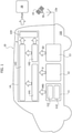
- Figure 1 is a diagram of a positioning device ("engine") 10 configured to provide a measurement of (absolute) position (latitude, longitude and altitude, for instance) and motion (velocity and attitude, for instance) of a vehicle V (that is a mobile "platform”) equipped therewith.
- engine 10 configured to provide a measurement of (absolute) position (latitude, longitude and altitude, for instance) and motion (velocity and attitude, for instance) of a vehicle V (that is a mobile "platform”) equipped therewith.
- the device 10 is mounted onboard a four-wheeled land vehicle.
- the device 10 is mounted onboard a four-wheeled land vehicle.
- Such an assumption is purely exemplary and in no way limiting: one or more embodiments may be coupled to notionally any kind of wheeled vehicle V.
- the device 10 may comprise:
- a positioning device 13 comprising a GNSS (Global Navigation Satellite System) hardware receiver 13 configured to provide absolute positioning signal data SD, for instance receiving GNSS signals from one or more satellites 15 (via an antenna 13a optionally included in the device 10) and processing these signals in order to obtain measurements about the satellite distance from earth and relative motion, supplying them as satellite position data SD.
- GNSS Global Navigation Satellite System
- any kind of (absolute) positioning device 13 may be employed as one or more embodiments.
- this may comprise a mobile phone configured to provide an absolute positioning data signal.
- the position processor 14 includes a (software) processing pipeline running thereon and comprising:
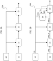
- a fusion processing stage 20A as exemplified in Figure 2A may comprises a processing pipeline including:
- performing alignment processing in the alignment stage 21 may comprise:
- applying calibration processing to the aligned dataset IMD_a in the calibration stage 21 may be directed at reducing systematic errors components which may be present in data sensed by IMU sensor 11, producing the calibrated dataset IMD_c as a result, the calibration processing comprising:
- applying PVA filtering processing in the PVA filtering stage 23 may comprise: evaluating quality of GNSS position, velocity and attitude, e.g., receiving such an evaluation from the GNSS stage 13, and/or calculating it using the calibrated dataset IMU_c received from the calibration stage 22 according to INS (inertial navigation system) theory, in a way known per se.
- INS inertial navigation system
- One or more embodiments may be based on the recognition that drawbacks of existing solutions can be overcome, obtaining an accurate velocity measurement from the IMU 11, by applying (direct) frequency response analysis to the signals IMD sensed by the IMU 11 and extracting therefrom a frequency component indicative of, for instance, proportional to, (wheel) angular rotation rate.
- Such fusion processing may comprise a processing pipeline 20B as exemplified in Figure 2B : this pipeline lends itself to being implemented in a stage of the device 10 such as 143.
- the pipeline 20B as exemplified in Figure 2B may comprise an additional (virtual) odometer stage 24 coupled to the GNSS receiver 13, the calibration stage 22 and the PVA filter 23.
- the virtual odometer stage 24 is configured to receive velocity data from the GNSS receiver 13, the calibrated data IMD c from the calibration stage 22 and velocity data filtered from the PVA filter stage 23, and calculate an odometer velocity dataset (that is, velocity data calculated in the virtual odometer stage 24) which is supplied to the PVA filter stage 23.
- Figure 3 is a diagram showing possible details of the processing pipeline of Figure 2 , primarily expanding processing details of the virtual odometer stage 24.
- the data IMD from the IMU 11 may comprise a plurality of signals, e.g., three acceleration signals Ax, Ay, Az sensed by the accelerometer 112 and three gyroscopic signals Gx, Gy, Gz sensed by the gyroscope 114; data from the GNSS 13 provided to the odometer stage 22 may substantially comprise velocity measurement data.
- the virtual odometer stage 24 may comprise:
- Figure 4 is an exemplary diagram of the IMU power detecting stage 26.
- such a power detecting stage 26 may comprise:
- FIG. 5A is an exemplary diagram of a processing pipeline which may be incorporated in the frequency sweeping stage 260, which may comprise:
- one or more embodiments may produce the set of frequency points using any other type of spatial distribution, such as a Gaussian distribution where more density points are present close to the center frequency, for instance.
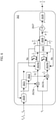
- Figure 6 is an exemplary diagram of an axial power detecting processing pipeline 262 which may be implemented in each set of (parallel) axial power detecting sub-stages 262a, 262b, 262c, 262d, 262e, 262f, the pipeline 262 comprising:
- the pipeline 262 may further comprise a timer stage 2625 coupled to the pair of integrator stage 2623a, 2623b and configured to trigger reset of the integrator processing (e.g., setting them to an initial zero value) as a function of a certain time threshold being reached, such as a time interval equal to a period of rotation T being reached; the timer stage 2625 may provide a pair of signals Q i T , I i T equal to the time integral of signals Q i , I i for such a period T of time.
- a timer stage 2625 coupled to the pair of integrator stage 2623a, 2623b and configured to trigger reset of the integrator processing (e.g., setting them to an initial zero value) as a function of a certain time threshold being reached, such as a time interval equal to a period of rotation T being reached; the timer stage 2625 may provide a pair of signals Q i T , I i T equal to the time integral of signals Q i , I i for such a period T of time
- the integrating stage 2624 comprises an adding node at which the input signal xi is added, as a function of a resettable switch, with either a zero signal or a signal resulting from applying a single pole to the previous value of the input signal.
- the pair of integrated signals are further processed in a power calculating stage 2626 coupled to the timer stage 2625 and configured to receive such time-integrated signals Q i T , I i T and to apply power calculation processing thereto as discussed in the following, producing an i-th calculated power Pi as a result.
- the processing pipeline may further comprise a check stage 2627 coupled to the power calculating stage 2626, the check stage 2627 configured to increment a counter J and to check if processing has been performed a number of times equal to the number N of frequency points in the sequence of frequency points f 1 , ..., f i , ..., f N so that:
- Figure 7C reproduces an exemplary plot of collected values of the calculated power values Pi as a function of the frequency points in the sequence of frequency points f 1 , ..., f i , ..., f N , where the relative maximum power value Pmax is detected at the frequency f y .
- the detected frequencies f ax , f ay , f gx , f gy related to axial spectral power densities P ax , P ay , P gx , P gy relative to the axes x and y are provided and processed in the wheel frequency detecting stage 27, comprising:
- the first calculating stage 27 may be configured to compute a weighted average, facilitating giving more importance to some axes, or a logical algorithm selecting one of the axes as a function of various parameters, such as the detected power P i , for instance.
- the wheel size estimating stage 28 comprises a pipeline to estimate wheel size by comparing detected rotation frequency against a reference velocity, such as velocity v GNSS provided by the GNSS receiver 13, for instance.
- the velocity signals provided by other systems may be used, such as the velocity from the (real) odometer or the estimated velocity vin from the PVA filter stage 23.
- a Kalman filter (known per se to those of skill in the art) was found suitable for use in the wheel size detecting stage 28.
- a detection method is purely exemplary and in no way limiting, being otherwise understood that other methods may be suitable, such as a LS algorithm computed over a set of observations or a (low-pass) filter, for instance.
- a method comprises:
- applying said frequency domain transformation to the filtered dataset comprises:
- said spectral power calculation (for instance, 262, 262a, 262b, 262c, 262d, 262e, 262f) of individual signals (for instance, y i ) in said filtered dataset of filtered data comprises:
- the method comprises:
- said selecting comprises selecting a distribution function out of the group of distribution functions comprising uniform, weighted and gaussian distribution functions.
- said calculating as a function of said set of power-maximizing frequencies in said frequency analyzed dataset of frequency analyzed data, a wheel angular frequency signal (for instance, f w ) indicative of an angular frequency of a wheel of the wheeled vehicle (for instance, V), comprises:
- providing said wheel size signal (for instance, C w ) indicative of a radial size of a wheel of the wheeled mobile object comprises using a Kalman filter (for instance, K).
- applying said pre-processing for instance, 21, 22, 23 to motion data in said motion dataset as a function of absolute positioning data in said absolute positioning, comprises:
- a position engine device (for instance, 10) is configured to be coupled to with at least one inertial sensing unit (for instance, 11, 112, 114) and at least one global navigation system transceiver (for instance, 13) configured to be equipped on a wheeled vehicle (for instance, 100), the positioning engine device comprising processing circuitry (for instance, 14, 143) configured to provide a fused dataset (for instance, F) indicative position, velocity and attitude (for instance, P,V,A) information of the wheeled vehicle to a user circuit (for instance, 16) with the method according to one or more embodiments.
- processing circuitry for instance, 14, 143
- a wheeled vehicle (for instance, 100) is equipped with:
- said at least one inertial sensing unit comprises a triaxial accelerometer (for instance, 112) and a triaxial gyroscope (for instance, 114) .
- a computer program product is loadable in the memory of at least one processing circuit (for instance, 14, 143) and comprises software code portions for executing the steps of the method according to one or more embodiments when the product is run on at least one processing circuit.
Landscapes
- Engineering & Computer Science (AREA)
- Radar, Positioning & Navigation (AREA)
- Remote Sensing (AREA)
- Physics & Mathematics (AREA)
- Automation & Control Theory (AREA)
- Mathematical Physics (AREA)
- Transportation (AREA)
- Mechanical Engineering (AREA)
- General Physics & Mathematics (AREA)
- Computer Networks & Wireless Communication (AREA)
- Navigation (AREA)
Abstract
Description
- The description relates to the field of navigation, i.e. the capability of a device to determine a user position, velocity (speed) and attitude (i.e. 3D direction).
- One or more embodiments may refer to techniques for providing navigation information, for instance in a land vehicle, including position and attitude information.
- A currently leading technology for positioning applications in the automotive field is GNSS (Global Navigation Satellite System), which is conventionally used in navigation systems including navigation and telematics.
- Emerging applications such as autonomous driving, car- to-car (and car-to-infrastructure) communications will expectedly foster further technological challenges in the near future.
- While capable of providing an absolute position reference, a GNSS receiver may possibly exhibit various drawbacks: for instance, it relies on a satellite signal which may be unavailable (e.g. indoor, tunnels) or corrupted (e.g. urban environments, reflections and/or multipath).
- A motion and position sensor (MPS) electronic device may be used in a number of applications in various fields, such as automotive and consumer electronics, for instance. In the automotive field, it may be located onboard a vehicle.
- Such an electronic device may comprise:
- a GNSS receiver, configured to provide an accurate position of the vehicle;
- an inertial measurement unit (IMU), including one or more inertial sensors (gyroscope, accelerometer, etc.), configured to provide (redundant) position information which may be exploited as a backup in case GNSS is either unavailable or corrupted, as mentioned, and
- a processing unit coupled to the GNSS receiver and to the IMU, such a unit being configured to receive data and to deploy these data to the benefit of an (external) user application.
- As known to those of skill in the art, the IMU may provide position information according to classic theory of inertial navigation, namely integrating angular rates sensed by a gyroscope in order to obtain vehicle attitude data (pitch, roll, yaw angles with respect to reference framework, for instance) and integrating (twice) an acceleration/velocity (vehicle velocity, for instance) sensed by an accelerometer.
- Accuracy of this processing may be affected by:
- calibration quality, which may be a key figure of merit concerning the gyroscope;
- the capability of compensating earth gravity superimposed to the acceleration as measured by the accelerometer: if not properly compensated, this may lead to errors on velocity integration (and consequently on position).
- Existing solutions to filter gravity contributions from accelerometer measurements rely on attitude compensation: this may involve rotating the accelerometer measurements by angles equal to attitude angles thus mapping them into a different reference frame, the so-called "navigation frame", which comprises a triad of axes (x, y, z) with x and y axes parallel to the earth surface and the z axis orthogonal thereto. In such a reference frame, the gravitational acceleration vector may be expressed as a vector g, e.g., g=[0, 0, 9.81 m/s2], whose coordinates may be subtracted from data from the accelerometer.
- Existing solutions may suffer from various drawbacks:
- calculation of the (vehicle) attitude may lead to velocity and position errors due to drifts in gyroscope measurements likely to increase with time (e.g., due to wear of the sensor); correcting such drifts may involve observing instant pitch/roll values provided by the accelerometer, with such an observation being possible mainly under special conditions (e.g. with vehicle stopped);
- detecting further errors likely to affect the accelerometer sensor (e.g., cross-axis sensitivity) may involve measurements (and tailored compensation) in the sensor production line, which may lead to increased costs and complexity.
- Due to the aforementioned time-evolving drift, in the absence of a GNSS signal, conventional inertial navigation systems can provide reliable navigation only for a limited period of time (for instance for about 1 minute): errors may undesirably grow beyond tolerances after such period.
- An object of one or more embodiments is to contribute in overcoming the aforementioned drawbacks.
- According to one or more embodiments, that object can be achieved by means of a method having the features set forth in the claims that follow.
- One or more embodiments may relate to a corresponding device.
- A vehicle motion and position sensor (VMPS) device (engine) may be exemplary of such a device, for instance.
- One or more embodiments may relate to a corresponding system.
- One or more embodiments may relate to the method as a computer-implemented method.
- To that effect, one or more embodiments may comprise a computer program product loadable in the memory of at least one processing circuit (e.g., a computer) and comprising software code portions for executing the steps of the method when the product is run on at least one processing circuit. As used herein, reference to such a computer program product is understood as being equivalent to reference to computer-readable medium containing instructions for controlling the processing system in order to co-ordinate implementation of the method according to one or more embodiments. Reference to "at least one computer" is intended to highlight the possibility for one or more embodiments to be implemented in modular and/or distributed form.
- One or more embodiments may be suitable for loading in the memory of at least one processing circuit (e.g., a micro-controller) and comprise software code portions for executing the steps of the method when the product is run on at least one processing circuit.
- The claims are an integral part of the technical teaching provided herein with reference to the embodiments.
- One or more embodiments may be designed to obtain "stand-alone" vehicle velocity measurements from sensed IMU signals without integration and gravity compensation, independently of the presence and the quality of GNSS signals.
- One or more embodiments may facilitate producing a user position and velocity measurement which has an increased, stable accuracy for longer periods of time with respect to existing solutions.
- One or more embodiments may facilitate cost savings in production, for instance by skipping dedicated calibration procedures for IMU devices.
- One or more embodiments may involve processing of measurement signals presenting an error distribution which may be advantageously easier to compensate: for instance, a Gaussian distribution without bias may facilitate canceling out systematic errors.
- One or more embodiments will now be described, by way of non-limiting example only, with reference to the annexed Figures, wherein:
-
Figure 1 is a diagram of a positioning device (engine) as exemplified herein, -
Figures 2A and 2B are diagrams exemplary of methods of processing sensor data, -
Figure 3 is a diagram exemplary of a portion of the diagram ofFigure 2B , -
Figure 4 is a diagram exemplary of a portion of the diagram ofFigure 3 , -
Figures 5A and 5B are diagrams exemplary of a portion ofFigure 4 , -
Figure 6 is a diagram exemplary of a portion ofFigure 4 , -
Figures 7A, 7B and 7C are diagrams exemplary of portions ofFigure 6 , -
Figures 8 and 9 are diagrams exemplary of portions of the diagram ofFigure 3 . - In the ensuing description, one or more specific details are illustrated, aimed at providing an in-depth understanding of examples of embodiments of this description. The embodiments may be obtained without one or more of the specific details, or with other methods, components, materials, etc. In other cases, known structures, materials, or operations are not illustrated or described in detail so that certain aspects of embodiments will not be obscured.
- Reference to "an embodiment" or "one embodiment" in the framework of the present description is intended to indicate that a particular configuration, structure, or characteristic described in relation to the embodiment is comprised in at least one embodiment. Hence, phrases such as "in an embodiment" or "in one embodiment" that may be present in one or more points of the present description do not necessarily refer to one and the same embodiment.
- Moreover, particular conformations, structures, or characteristics may be combined in any adequate way in one or more embodiments.
- The headings/references used herein are provided merely for convenience and hence do not define the extent of protection or the scope of the embodiments.
- Also, throughout the figures annexed herein, like parts or elements are indicated with like references/numerals and for brevity a corresponding description will not be repeated for each and every figure.
-
Figure 1 is a diagram of a positioning device ("engine") 10 configured to provide a measurement of (absolute) position (latitude, longitude and altitude, for instance) and motion (velocity and attitude, for instance) of a vehicle V (that is a mobile "platform") equipped therewith. - For the sake of simplicity, the following description will assume that the
device 10 is mounted onboard a four-wheeled land vehicle. Such an assumption is purely exemplary and in no way limiting: one or more embodiments may be coupled to notionally any kind of wheeled vehicle V. - As exemplified in
Figure 1 , thedevice 10 may comprise: - an inertial measurement unit (IMU) 11, e.g., digital six-axes IMU, comprising a (e.g., triaxial)
gyroscope 112 and a (e.g., triaxial)accelerometer 114, providing inertial measurement data IMD as an output; - a
barometer unit 12, e.g. a digital barometer, providing barometric pressure data p as an output; - an
absolute positioning unit 13 configured to provide absolute positioning signal data SD as an output; - processing
circuitry 14 configured to receive and process (executing software code portions, for instance) data IMD, p, SD as provided as output bycomponents processing circuitry 14 may be configured to compute a vehicle position P and motion quantities, specifically velocity V and attitude A. - For the sake of simplicity, one or more embodiments are discussed in the following with respect to a
positioning device 13 comprising a GNSS (Global Navigation Satellite System)hardware receiver 13 configured to provide absolute positioning signal data SD, for instance receiving GNSS signals from one or more satellites 15 (via anantenna 13a optionally included in the device 10) and processing these signals in order to obtain measurements about the satellite distance from earth and relative motion, supplying them as satellite position data SD. It is noted that such an example is in no way limiting, as notionally any kind of (absolute)positioning device 13 may be employed as one or more embodiments. For instance, this may comprise a mobile phone configured to provide an absolute positioning data signal. - As exemplified in
Figure 1 , theposition processor 14 includes a (software) processing pipeline running thereon and comprising: - a
sensor interface stage 141 comprising a set of drivers, e.g. I2C and/or SPI, configured to interface sensor (registers) of theIMU 11 and thebarometer 12 to extract the IMD data and barometric pressure p data and format such extracted IMD data and barometric pressure p data in a format used by afusion software module 143, as discussed in the following; - an absolute positioning
data processing stage 142 configured to process absolute positioning data, such as a GNNSS processing stage configured to process satellite position data SD and calculate a GNSS-based position and altitude estimate, for instance; - a
fusion processing stage 143 configured to apply data fusion to the data IMD, p, SD as provided from theIMU 11, thebarometer 12 and theGNSS 13 and processed by thesensor interface 141 andGNSS software module 142 respectively. As a result of such data fusion, fused GNSS/sensor output data F are produced by thefusion processing stage 143; - a UART (Universal Asynchronous Receiver-Transmitter)
driver 144 configured to transmit fused GNSS/Sensor F data as vehicle position P, velocity V and attitude A values and provide them to one or more (external) user circuits and/or applications, such as an advanced driver assistance system (ADAS), for instance. - In a conventional manner, a
fusion processing stage 20A as exemplified inFigure 2A may comprises a processing pipeline including: - an
alignment stage 21, configured to receive respective signals IMD, SD from the GNSS andIMU devices - a
calibration stage 22, coupled to thealignment stage 21 and to theGNSS system 13; thecalibration stage 22 is configured to receive the respective signals therefrom and apply calibration processing to such signals, obtaining a calibrated dataset IMD_c as a result, - a position-velocity-attitude (PVA)
filter stage 23 coupled to thecalibration stage 22 and to theGNSS system 13; thePVA filter stage 23 is configured to receive the respective signals IMD_c, VGNSS therefrom and apply to these signalsPVA filtering processing 23, obtaining a fused dataset F as a result. - For instance, performing alignment processing in the
alignment stage 21 may comprise: - detecting, e.g. by low-pass filtering and comparing the acceleration measured by x axis and versus the one which can be derived by GNSS (differentiating vehicle speed, for instance), the angles between reference frames of the
IMU sensor 11 and the navigation frame, such as pitch, roll and yaw angles where pitch and the roll represent the displacement among sensor (x,y) and vehicle horizontal plans and yaw is the angle separating the direction ax1 of a first x axis of thesensor 11 from a forward direction of the vehicle; - applying rotational mapping to the sensor frame using the detected angles (e.g. using Direction Cosine Matrix or quaternion methods known per se), obtaining the aligned signals of the aligned dataset IMD_a as a result.
- For instance, applying calibration processing to the aligned dataset IMD_a in the
calibration stage 21 may be directed at reducing systematic errors components which may be present in data sensed byIMU sensor 11, producing the calibrated dataset IMD_c as a result, the calibration processing comprising: - in order to remove biasing errors due to motion contribution from the received dataset IMD_a, applying low pass filters tuned at different cutoff frequencies to the dataset IMD_a,
- in order to remove errors due to scale factors from the received dataset IMD a, comparing the aligned IMU signals IMD_a with GNSS signals.
- For instance, applying PVA filtering processing in the
PVA filtering stage 23 may comprise:
evaluating quality of GNSS position, velocity and attitude, e.g., receiving such an evaluation from theGNSS stage 13, and/or calculating it using the calibrated dataset IMU_c received from thecalibration stage 22 according to INS (inertial navigation system) theory, in a way known per se. - One or more embodiments may be based on the recognition that drawbacks of existing solutions can be overcome, obtaining an accurate velocity measurement from the
IMU 11, by applying (direct) frequency response analysis to the signals IMD sensed by theIMU 11 and extracting therefrom a frequency component indicative of, for instance, proportional to, (wheel) angular rotation rate. - Such fusion processing may comprise a
processing pipeline 20B as exemplified inFigure 2B : this pipeline lends itself to being implemented in a stage of thedevice 10 such as 143. - In comparison with
pipeline 20A, thepipeline 20B as exemplified inFigure 2B may comprise an additional (virtual)odometer stage 24 coupled to theGNSS receiver 13, thecalibration stage 22 and thePVA filter 23. As exemplified herein, thevirtual odometer stage 24 is configured to receive velocity data from theGNSS receiver 13, the calibrated data IMD c from thecalibration stage 22 and velocity data filtered from thePVA filter stage 23, and calculate an odometer velocity dataset (that is, velocity data calculated in the virtual odometer stage 24) which is supplied to thePVA filter stage 23. -
Figure 3 is a diagram showing possible details of the processing pipeline ofFigure 2 , primarily expanding processing details of thevirtual odometer stage 24. - As exemplified in
Figure 3 , the data IMD from theIMU 11 may comprise a plurality of signals, e.g., three acceleration signals Ax, Ay, Az sensed by theaccelerometer 112 and three gyroscopic signals Gx, Gy, Gz sensed by thegyroscope 114; data from theGNSS 13 provided to theodometer stage 22 may substantially comprise velocity measurement data. - As exemplified in
Figure 3 , thevirtual odometer stage 24 may comprise: - a filter stage 25 (high-pass or low-pass filter, for instance), configured to receive the calibrated dataset IMD_c (comprising a respective set of calibrated signals Ax_c, Ay_c, Az_c, Gx_c, Gy_c, Gz_c) and to apply (high/low-pass) filtering thereto, obtaining a filtered calibrated dataset Ax_f, Ay_f, Az_f, Gx_f, Gy_f, Gz_f;
- a
power detecting stage 26 coupled to thefilter stage 25, to thePVA filter stage 23 and to an output of a (wheel size)estimator stage 28 via a feedback branch fb. Thepower detecting stage 26 may be configured to receive the filtered velocity from thePVA filter 23, the calibrated filtered dataset Ax_f, Ay_f, Az_f, Gx_f, Gy_f, Gz_f from thefilter stage 25 and a feedback signal (initially zero) from the feedback branch fb and to produce a frequency analyzed dataset comprising calculated spectral power density signals Pax, Pay, Paz, Pgx, Pgy, Pgz and frequencies fax, fay, faz, fgx, fgy, fgz as discussed in the following. Spectral power density signals Pax, Pay, Paz, Pgx, Pgy, Pgz may be obtained by applying frequency domain transformation to the input calibrated filtered dataset Ax_f, Ay_f, Az_f, Gx_f, Gy_f, Gz_f and by calculating spectral power in a frequency range Fr which may be determined as a function of the vehicle velocity vin estimated byGNSS 13, where for signals of the calibrated filtered dataset Ax_f, Ay_f, Az_f, Gx_f, Gy_f, Gz_f, the respective frequencies fax, fay, faz, fgx, fgy, fgz having the highest power are selected; - a (wheel)
frequency detecting stage 27 coupled to the IMUpower detecting stage 26 and to amixer stage 29 via a feedforward branch ff; thefrequency detecting stage 27 may be configured to receive the frequency analyzed dataset Pax, Pay, Paz, Pgx, Pgy, Pgz, fax, fay, faz, fgx, fgy, fgz therefrom, thefrequency detecting stage 27 configured to provide a (wheel) rotation frequency signal fw by calculating an average of the received frequencies fax, fay, faz, fgx, fgy, fgz; - a (wheel)
size estimating stage 28 coupled to theGNSS receiver 13 and to thefrequency detecting stage 27 and configured to provide a signal Cw indicative of a (wheel) size, - a
mixer stage 29 which receives the signal Cw indicative of a (wheel) size from thesize estimating stage 28 and the rotation frequency signal fw from thefrequency detecting stage 27 and to apply mixingprocessing 29 thereto, producing the (virtual) odometer dataset vo as a result which is estimated from the calculated frequency fw and the size of the wheel Cw. -
Figure 4 is an exemplary diagram of the IMUpower detecting stage 26. - As exemplified in
Figure 4 , such apower detecting stage 26 may comprise: - a frequency
sweeping stage 260 having a configurable frequency range parameter Fr and a configurable number of points parameter N, thefrequency sweep stage 260 configured to receive the wheel size estimate dataset Cw from thesize estimator stage 28 and the velocity value vin from thePVA filter 23 and to provide a set of frequency ranges f1, ..., fi,..., fN to be used to process the calibrated filtered dataset Ax_f, Ay_f, Az_f, Gx_f, Gy_f, Gz_f input to the detectingstage 26, - a set of (parallel) axial power detecting sub-stages 262a, 262b, 262c, 262d, 262e, 262f, one per respective axis of the respective accelerometer/
gyroscope -
Figure 5A is an exemplary diagram of a processing pipeline which may be incorporated in the frequencysweeping stage 260, which may comprise: - a
divider stage 2600 configured to receive the wheel size estimate Cw and the velocity value vin from thePVA filter 23 and to obtain an estimate of a central frequency fc as a result of calculating a ratio of velocity vin over wheel (radius) size Cw, e.g., fc=vin/Cw; - a frequency
sweep configuration stage 2602 coupled to thedivider stage 2600 and configured to produce a sequence of frequency points f1, ..., fi, ..., fN as a function of the configurable number of points parameter N and frequency range parameter Fr. The frequencysweep configuration stage 2602 may produce the sequence of frequency points f1, ..., fi, ..., fN having a certain spatial distribution therebetween. - As exemplified in
Figure 5B , the points are uniformly distributed using a "linspace" method where the central frequency fc is placed at the center of the frequency range FR and frequency points f1, ..., fi, ..., fN are equidistant by a distance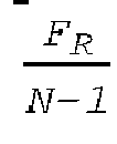

- It is noted that such a distribution of points is purely exemplary and in no way limiting, being otherwise understood that one or more embodiments may produce the set of frequency points using any other type of spatial distribution, such as a Gaussian distribution where more density points are present close to the center frequency, for instance.
-
Figure 6 is an exemplary diagram of an axial power detectingprocessing pipeline 262 which may be implemented in each set of (parallel) axial power detecting sub-stages 262a, 262b, 262c, 262d, 262e, 262f, thepipeline 262 comprising: - a
frequency setting stage 2620 coupled to a pair ofsignals generators frequency setting stage 2620 configured to receive the sequence of frequency points f1, ..., fi, ..., fN from the frequencysweeping stage 260 and to configure the signals generators to produce signals having a frequency equal to one of the frequency points of the received sequence of frequency points f1, ..., fi, ..., fN; - a pair of
parallel mixer stages - a
first mixer 2623a coupled to the first, e.g., sine,signal generator 2621 and configured to apply mixer processing between the signal from thegenerator 2621 and a axial data signal yi of the of the set of calibrated filtered dataset Ax_f, Ay_f, Az_f, Gx_f, Gy_f, Gz_f input to the detectingstage 26, producing a first mixed signal Qi as a result, and - a
second mixer 2623b coupled to the second, e.g., sine,signal generator 2622 and configured to apply mixer processing between the signal from thegenerator 2622 and the same axial data signal yi provided to thefirst mixer stage 2623a, producing a second mixed signal Ii as a result; - a pair of parallel integrating
stages stage 2624a coupled to thefirst mixer stage 2623a and configured to receive the first mixed signal Qi therefrom and a second integratingstage 2624b coupled to thesecond mixer stage 2623b and configured to receive therefrom the second mixed signal Ii, the first and second integratingstages 
- a
- As exemplified in
Figure 6 , thepipeline 262 may further comprise atimer stage 2625 coupled to the pair ofintegrator stage timer stage 2625 may provide a pair of signals

- As exemplified in
Figure 7A , the integratingstage 2624 comprises an adding node at which the input signal xi is added, as a function of a resettable switch, with either a zero signal or a signal resulting from applying a single pole to the previous value of the input signal. - The
integrator stage 2624 as exemplified inFigure 7A provides an output signal yt which may be expressed, at any time instant t, as follows:
- As exemplified in
Figure 5 , the pair of integrated signals are further processed in apower calculating stage 2626 coupled to thetimer stage 2625 and configured to receive such time-integrated signals

- As exemplified in
Figure 7B , thepower calculating stage 2626 may receive the pair of signals Qi T, Ii T and elevate each to the second power before adding them and calculating the square root of their sum, producing an estimate of signal power at the j-th frequency of the sequence of frequency points; thus, the calculated power value Pi may be expressed as:
- As exemplified in
Figure 6 , the processing pipeline may further comprise acheck stage 2627 coupled to thepower calculating stage 2626, thecheck stage 2627 configured to increment a counter J and to check if processing has been performed a number of times equal to the number N of frequency points in the sequence of frequency points f1, ..., fi, ..., fN so that: - if the counter J has reached or gone beyond the value of N processing is terminated,
- else, that is if the counter J is below the value N, the i-th calculated power Pi is passed on and the
frequency setting stage 2620 is triggered to reconfigure the signal generators to produce signals with a (i+1-th) frequency value equal to a frequency point in the sequence of frequency points f1, ..., fi, ..., fN following the (i-th) frequency point already "used"; and - a peak (maximum)
power detecting stage 2628 configured to collect each i-th calculated power values Pi processed at each j-th iteration of theprocessing 262, obtaining a spectral power density dataset Py, the maximumpower detecting stage 2628 configured to select a relative maximum value among the values of spectral power density dataset Py and to provide the frequency at which the power density dataset Py calculated is maximum as an output fy. -
Figure 7C reproduces an exemplary plot of collected values of the calculated power values Pi as a function of the frequency points in the sequence of frequency points f1, ..., fi, ..., fN, where the relative maximum power value Pmax is detected at the frequency fy. - As exemplified in
Figures 3 and8 , the detected frequencies fax, fay, fgx, fgy related to axial spectral power densities Pax, Pay, Pgx, Pgy relative to the axes x and y (of the "navigation reference frame, for instance) are provided and processed in the wheelfrequency detecting stage 27, comprising: - a
first calculations stage 270 configured to process the frequencies fax, fay, fgx, fgy, for instance by calculating an average or mean value µ of in ways per se known to those of skill in the art, and - a
second calculation stage 272 configured to calculate a standard deviation σ of the frequencies fax, fay, fgx, fgy, - a
comparator stage 274 configured to compare the calculated standard deviation σ with a pre-set threshold value ε, the comparator stage configured to trigger a switch sw as a result of the standard deviation remaining below the pre-set threshold ε, where when the switch sw is in a closed stage it is configured to provide the computed mean frequency value µ as an output fw of the wheelfrequency detection stage 27. - It is noted that such a way of processing frequencies in the first
calculating stage 270 is purely exemplary and in no way limiting, being otherwise understood that other types of processing to extract a detected frequency therefrom may be used. For instance, the first calculatingstage 27 may be configured to compute a weighted average, facilitating giving more importance to some axes, or a logical algorithm selecting one of the axes as a function of various parameters, such as the detected power Pi, for instance. - As exemplified in
Figure 9 , the wheelsize estimating stage 28 comprises a pipeline to estimate wheel size by comparing detected rotation frequency against a reference velocity, such as velocity vGNSS provided by theGNSS receiver 13, for instance. - In one or more embodiments, the velocity signals provided by other systems may be used, such as the velocity from the (real) odometer or the estimated velocity vin from the
PVA filter stage 23. - As exemplified in
Figure 9 , a Kalman filter (known per se to those of skill in the art) was found suitable for use in the wheelsize detecting stage 28. - As exemplified in
Figure 9 , the estimated wheel size Cw may be expressed as: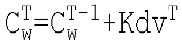
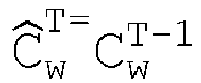


- with reference velocity vG=vGNSS, for instance.
- It is noted that such a detection method is purely exemplary and in no way limiting, being otherwise understood that other methods may be suitable, such as a LS algorithm computed over a set of observations or a (low-pass) filter, for instance.
- As exemplified herein, a method comprises:
- receiving a motion dataset (for instance, IMD) of motion data from at least one inertial sensing unit (for instance, 11, 112, 114) in a wheeled vehicle (for instance, 100),
- receiving an absolute positioning dataset (for instance, SD, vGNSS) of absolute positioning data from a global navigation system (for instance, 13) in the wheeled vehicle,
- applying pre-processing (for instance, 21, 22, 23) to motion data in the motion dataset as a function of absolute positioning data in the absolute positioning dataset (for instance, SD) and obtaining a pre-processed motion dataset of pre-processed motion data (for instance, IMD_a, IMD_c; Ax_c, Ay_c, Az_c, Gx_c, Gy_c, Gz_c) and at least one estimated velocity value (for instance, vin, vGNSS) of the wheeled vehicle as a result;
- applying pipeline data processing (for instance, 24) to pre-processed motion data in the pre-processed motion dataset as a function of the at least one estimated velocity value of the wheeled vehicle and obtaining a calculated virtual vehicle velocity (for instance, vo) as a result,
- applying position-velocity-attitude, PVA, filtering (for instance, 23) to pre-processed motion data in the pre-processed motion dataset and to at least one of absolute positioning data in the absolute positioning dataset and the calculated virtual vehicle velocity, and obtaining a fused dataset (for instance, F) of fused data indicative of position, velocity and attitude information of the vehicle as a result; and
- providing to a user circuit (for instance, 16) fused data in the fused dataset indicative of position, velocity and attitude information of the wheeled vehicle,
- wherein said pipeline data processing (for instance, 24) for obtaining said virtual vehicle velocity (for instance, vo) as a result comprises:
- high-pass or low-pass filtering (for instance, 25) pre-processed motion data in the pre-processed motion dataset and obtaining a filtered dataset of filtered data (for instance, Ax_f, Ay_f, Az_f, Gx_f, Gy_f, Gz_f) as a result;
- applying frequency-domain transformation (for instance, 26, 260, 262) to filtered data in the filtered dataset of filtered data and obtaining as a result a frequency analyzed dataset of frequency analyzed data (for instance, Pax, Pay, Paz, Pgx, Pgy, Pgz, fax, fay, faz, fgx, fgy, fgz) comprising individual spectral power density signals (for instance, Pax, Pay, Paz, Pgx, Pgy, Pgz) including a set of power-maximizing frequencies (for instance, fax, fay, faz, fgx, fgy, fgz) ;
- calculating, as a function of said set of power-maximizing frequencies (for instance, fax, fay, faz, fgx, fgy, fgz) in said frequency analyzed dataset of frequency analyzed data, a wheel angular frequency signal (for instance, fw) indicative of an angular frequency of a wheel of the wheeled vehicle and a wheel size signal (for instance, Cw) indicative of a radial size of said wheel of the wheeled vehicle,
- calculating (for instance, 29) said virtual vehicle velocity as a function of said wheel angular frequency signal and said wheel size signal.
- As exemplified herein, applying said frequency domain transformation to the filtered dataset comprises:
- selecting (for instance, 260) a frequency range (for instance, Fr) including a frequency value equal to a ratio of said estimated velocity value to said wheel size signal,
- selecting a distribution function (for instance, 2602) and producing (for instance, 2600) a sequence of (for instance, N) frequency values (for instance, fi,..., fi,..., fN) having a spatial distribution across said selected frequency range (for instance, Fr) determined by said selected distribution function (for instance, 2602),
- performing spectral power calculation (for instance, 262, 262a, 262b, 262c, 262d, 262e, 262f) of individual signals (for instance, yi) in said filtered dataset of filtered data as a function of said sequence of frequency values producing said individual spectral power density signals of said frequency analyzed dataset as a result.
- As exemplified herein, said spectral power calculation (for instance, 262, 262a, 262b, 262c, 262d, 262e, 262f) of individual signals (for instance, yi) in said filtered dataset of filtered data comprises:
- sequentially selecting (for instance, 2620) a frequency point value (for instance, fi) in said sequence of frequency values,
- generating (for instance, 2621, 2622) a first (for instance, 2621) and a second (for instance, 2622) periodic signal at said selected frequency point value, with said first and second periodic signals being in quadrature therebetween,
- applying mixing processing (for instance, 2623a, 2632b) between an individual signal (for instance, yi) of said filtered dataset of filtered data and said first and second generated periodic signals, obtaining a pair of mixed signals (for instance, Qi, Ii) as a result,
- performing periodic time-integration (for instance, 2624a, 2624b) of the first (for instance, Qi) and second (for instance, Ii) mixed signals, producing a pair of integrated mixed signals, wherein said periodic time-integration (for instance, 2624a, 2624b) comprises triggering reset (for instance, R) of said time-integration as a result of reaching a pre-set (for instance, 2625) time-threshold equal proportional to a period of wheel rotation,
- calculating a square root of a sum of the second power (for instance, 2626) of the respective integrated mixed signals,
- iterating N times (for instance, 2627) said sequentially selecting, said applying mixing processing, said performing periodic time-integration and said calculating the square root of the sum of the second power, providing an individual spectral power signal (for instance, Pi) as a result.
- As exemplified herein, the method comprises:
- detecting (for instance, 2628) power-maximizing frequency values (for instance, fi) at which each individual power density signal (for instance, Pi) in said individual spectral power density signals has a relative maximum spectral power value (for instance, Pmax) , and
- collecting (for instance, 262a, 262b, 262c, 262d, 262e, 262f) said detected power-maximizing frequency values (fi) in said set of power-maximizing frequencies.
- As exemplified herein, said selecting (for instance, 2602) a distribution function comprises selecting a distribution function out of the group of distribution functions comprising uniform, weighted and gaussian distribution functions.
- As exemplified herein, said calculating, as a function of said set of power-maximizing frequencies in said frequency analyzed dataset of frequency analyzed data, a wheel angular frequency signal (for instance, fw) indicative of an angular frequency of a wheel of the wheeled vehicle (for instance, V), comprises:
- calculating (for instance, 270) an average value and a variance of said set of power-maximizing frequencies in said frequency analyzed dataset,
- verifying (for instance, 272) that said calculated variance of said set of power-maximizing frequencies is within (e.g., below) a pre-set threshold, providing (for instance, SW) an angular frequency signal (for instance, fw) equal to said calculated average value of said set of power-maximizing frequencies as a result.
- As exemplified herein, providing said wheel size signal (for instance, Cw) indicative of a radial size of a wheel of the wheeled mobile object comprises using a Kalman filter (for instance, K).
- As exemplified herein, applying said pre-processing (for instance, 21, 22, 23) to motion data in said motion dataset as a function of absolute positioning data in said absolute positioning, comprises:
- performing alignment (for instance, 21) of said motion dataset as a function of said absolute positioning dataset, obtaining an aligned motion dataset (for instance, IMD_a) as a result, and
- calibrating (for instance, 22) said motion dataset (for instance, IMD) as a function of said absolute positioning dataset (for instance, SD), obtaining a calibrated motion dataset (IMD_c) as a result.
- As exemplified herein, a position engine device (for instance, 10) is configured to be coupled to with at least one inertial sensing unit (for instance, 11, 112, 114) and at least one global navigation system transceiver (for instance, 13) configured to be equipped on a wheeled vehicle (for instance, 100), the positioning engine device comprising processing circuitry (for instance, 14, 143) configured to provide a fused dataset (for instance, F) indicative position, velocity and attitude (for instance, P,V,A) information of the wheeled vehicle to a user circuit (for instance, 16) with the method according to one or more embodiments.
- As exemplified herein, a wheeled vehicle (for instance, 100) is equipped with:
- at least one inertial sensing unit (for instance, 11, 112, 114),
- at least one global navigation system transceiver (for instance, 13), preferably a global navigation satellite system, GNSS, and
- a positioning engine device (for instance, 10) according to one or more embodiments,
- wherein said positioning engine device is coupled to said at least one inertial sensing unit and said at least one global navigation system transceiver.
- As exemplified herein, said at least one inertial sensing unit comprises a triaxial accelerometer (for instance, 112) and a triaxial gyroscope (for instance, 114) .
- As exemplified herein, a computer program product is loadable in the memory of at least one processing circuit (for instance, 14, 143) and comprises software code portions for executing the steps of the method according to one or more embodiments when the product is run on at least one processing circuit.
- It will be otherwise understood that the various individual implementing options exemplified throughout the figures accompanying this description are not necessarily intended to be adopted in the same combinations exemplified in the figures. One or more embodiments may thus adopt these (otherwise non-mandatory) options individually and/or in different combinations with respect to the combination exemplified in the accompanying figures.
- Without prejudice to the underlying principles, the details and embodiments may vary, even significantly, with respect to what has been described by way of example only, without departing from the extent of protection. The extent of protection is defined by the annexed claims.
Claims (12)
- A method, comprising:receiving a motion dataset (IMD) of motion data from at least one inertial sensing unit (11, 112, 114) in a wheeled vehicle (100),receiving an absolute positioning dataset (SD, vGNSS) of absolute positioning data from a global navigation system (13) in the wheeled vehicle (100),applying pre-processing (21, 22, 23) to motion data in the motion dataset (IMD) as a function of absolute positioning data in the absolute positioning dataset (SD) and obtaining a pre-processed motion dataset of pre-processed motion data (IMD_a, IMD_c; Ax_c, Ay_c, Az_c, Gx_c, Gy_c, Gz_c) and at least one estimated velocity value (vin, vGNSS) of the wheeled vehicle (100) as a result;applying pipeline data processing (24) to pre-processed motion data in the pre-processed motion dataset (IMD_a, IMD_c; Ax_c, Ay_c, Az_c, Gx_c, Gy_c, Gz_c) as a function of the at least one estimated velocity value (vin, vGNSS) of the wheeled vehicle (100) and obtaining a calculated virtual vehicle velocity (vo) as a result,applying position-velocity-attitude, PVA, filtering (23) to pre-processed motion data in the pre-processed motion dataset (IMD_a, IMD_c; Ax_c, Ay_c, Az_c, Gx_c, Gy_c, Gz_c) and to at least one of absolute positioning data in the absolute positioning dataset (SD) and the calculated virtual vehicle velocity (vo), and obtaining a fused dataset (F) of fused data indicative of position, velocity and attitude information of the vehicle (100) as a result; andproviding to a user circuit (16) fused data in the fused dataset (F) indicative of position, velocity and attitude information of the wheeled vehicle (100),wherein said pipeline data processing (24) for obtaining said virtual vehicle velocity (vo) as a result comprises:high-pass or low-pass filtering (25) pre-processed motion data in the pre-processed motion dataset (IMD_a, IMD_c; Ax_c, Ay_c, Az_c, Gx_c, Gy_c, Gz_c) and obtaining a filtered dataset of filtered data (Ax_f, Ay_f, Az_f, Gx_f, Gy_f, Gz_f) as a result;applying frequency-domain transformation (26, 260, 262) to filtered data in the filtered dataset of filtered data (Ax_f, Ay_f, Az_f, Gx_f, Gy_f, Gz_f) and obtaining as a result a frequency analyzed dataset of frequency analyzed data (Pax, Pay, Paz, Pgx, Pgy, Pgz, fax, fay, faz, fgx, fgy, fgz) comprising individual spectral power density signals (Pax, Pay, Paz, Pgx, Pgy, Pgz) including a set of power-maximizing frequencies (fax, fay, faz, fgx, fgy, fgz) ;calculating, as a function of said set of power-maximizing frequencies (fax, fay, faz, fgx, fgy, fgz) in said frequency analyzed dataset of frequency analyzed data (Pax, Pay, Paz, Pgx, Pgy, Pgz, fax, fay, faz, fgx, fgy, fgz), a wheel angular frequency signal (fw) indicative of an angular frequency of a wheel of the wheeled vehicle (100) and a wheel size signal (Cw) indicative of a radial size of said wheel of the wheeled vehicle (100),calculating (29) said virtual vehicle velocity (vo) as a function of said wheel angular frequency signal (fw) and said wheel size signal (Cw).
- The method of claim 1, wherein:applying said frequency domain transformation (26, 260, 262) to the filtered dataset (Ax_f, Ay_f, Az_f, Gx_f, Gy_f, Gz_f) comprises:selecting (260) a frequency range (Fr) including a frequency value equal to a ratio of said estimated velocity value (vin, vGNSS) to said wheel size signal (Cw),selecting a distribution function (2602) and producing (2600) a sequence of N frequency values (fi,..., fi,..., fN) having a spatial distribution across said selected frequency range (Fr) determined by said selected distribution function (2602),performing spectral power calculation (262, 262a, 262b, 262c, 262d, 262e, 262f) of individual signals (yi) in said filtered dataset of filtered data (Ax_f, Ay_f, Az_f, Gx_f, Gy_f, Gz_f) as a function of said sequence of N frequency values (f1,..., fi,..., fN), producing said individual spectral power density signals (Pax, Pay, Paz, Pgx, Pgy, Pgz) of said frequency analyzed dataset (Pax, Pay, Paz, Pgx, Pgy, Pgz, fax, fay, faz, fgx, fgy, fgz) as a result.
- The method of claim 2, wherein said spectral power calculation (262, 262a, 262b, 262c, 262d, 262e, 262f) of individual signals (yi) in said filtered dataset of filtered data (Ax_f, Ay_f, Az_f, Gx_f, Gy_f, Gz_f) comprises:sequentially selecting (2620) a frequency point value (fi) in said sequence of N frequency values (f1,..., fi,..., fN),generating (2621, 2622) a first (2621) and a second (2622) periodic signal at said selected frequency point value (fi), with said first (2621) and second (2622) periodic signals being in quadrature therebetween,applying mixing processing (2623a, 2632b) between an individual signal (yi) of said filtered dataset of filtered data (Ax_f, Ay_f, Az_f, Gx_f, Gy_f, Gz_f) and said first (2621) and second (2622) generated periodic signals, obtaining a pair of mixed signals (Qi, Ii) as a result,performing periodic time-integration (2624a, 2624b) of the first (Qi) and second (Ii) mixed signals, producing a pair of integrated mixed signals, wherein said periodic time-integration (2624a, 2624b) comprises triggering reset (R) of said time-integration (2624a, 2624b) as a result of reaching a pre-set (2625) time-threshold equal proportional to a period of wheel rotation,calculating a square root of a sum of the second power (2626) of the respective integrated mixed signals,iterating N times (2627) said sequentially selecting (2620), said applying mixing processing (2623a, 2632b), said performing periodic time-integration (2624a, 2624b) and said calculating the square root of the sum of the second power (2626), providing an individual spectral power signal (Pi) as a result.
- The method of claim 2 or claim 3, comprising:detecting (2628) power-maximizing frequency values (fi) at which each individual power density signal (Pi) in said individual spectral power density signals (Pax, Pay, Paz, Pgx, Pgy, Pgz) has a relative maximum spectral power value (Pmax) , andcollecting (262a, 262b, 262c, 262d, 262e, 262f) said detected power-maximizing frequency values (fi) in said set of power-maximizing frequencies (fax, fay, faz, fgx, fgy, fgz) .
- The method of any of claims 2 to 4, wherein said selecting (2602) a distribution function comprises selecting a distribution function out of the group of distribution functions comprising uniform, weighted and gaussian distribution functions.
- The method of any of the previous claims, wherein said calculating, as a function of said set of power-maximizing frequencies (fax, fay, faz, fgx, fgy, fgz) in said frequency analyzed dataset of frequency analyzed data (Pax, Pay, Paz, Pgx, Pgy, Pgz, fax, fay, faz, fgx, fgy, fgz), a wheel angular frequency signal (fw) indicative of an angular frequency of a wheel of the wheeled vehicle (V), comprises:calculating (270) an average value and a variance of said set of power-maximizing frequencies (fax, fay, faz, fgx, fgy, fgz) in said frequency analyzed dataset (Pax, Pay, Paz, Pgx, Pgy, Pgz, fax, fay, faz, fgx, fgy, fgz) ,verifying (272) that said calculated variance of said set of power-maximizing frequencies (fax, fay, faz, fgx, fgy, fgz) is within a pre-set threshold, providing (SW) an angular frequency signal (fw) equal to said calculated average value of said set of power-maximizing frequencies (fax, fay, faz, fgx, fgy, fgz) as a result.
- The method of any of the previous claims, wherein providing said wheel size signal (Cw) indicative of a radial size of a wheel of the wheeled mobile object comprises using a Kalman filter (K).
- The method of any of the previous claims, wherein applying said pre-processing (21, 22, 23) to motion data in said motion dataset (IMD) as a function of absolute positioning data in said absolute positioning dataset (SD), comprises:performing alignment (21) of said motion dataset (IMD) as a function of said absolute positioning dataset (SD), obtaining an aligned motion dataset (IMD_a) as a result, andcalibrating (22) said motion dataset (IMD) as a function of said absolute positioning dataset (SD), obtaining a calibrated motion dataset (IMD_c) as a result.
- A position engine device (10) configured to be coupled to with at least one inertial sensing unit (11, 112, 114) and at least one global navigation system transceiver (13) configured to be equipped on a wheeled vehicle (100), the positioning engine device (10) comprising processing circuitry (14, 143) configured to provide a fused dataset (F) indicative position, velocity and attitude (P,V,A) information of the wheeled vehicle to a user circuit (16) with the method of any of claims 1 to 8.
- A wheeled vehicle (100), equipped with:at least one inertial sensing unit (11, 112, 114),at least one global navigation system transceiver (13), preferably a global navigation satellite system, GNSS, anda positioning engine device (10) according to claim 9,wherein said positioning engine device (10) is coupled to said at least one inertial sensing unit (11, 112, 114) and said at least one global navigation system transceiver (13).
- The wheeled vehicle (100) of claim 10, wherein said at least one inertial sensing unit (11, 112, 114) comprises a triaxial accelerometer (112) and a triaxial gyroscope (114).
- A computer program product loadable in the memory of at least one processing circuit (14, 143) and comprising software code portions for executing the steps of the method of any of claims 1 to 8 when the product is run on at least one processing circuit (14, 143) .
Applications Claiming Priority (1)
| Application Number | Priority Date | Filing Date | Title |
|---|---|---|---|
| IT202000021571 | 2020-09-11 |
Publications (2)
| Publication Number | Publication Date |
|---|---|
| EP3967976A1 true EP3967976A1 (en) | 2022-03-16 |
| EP3967976B1 EP3967976B1 (en) | 2023-06-14 |
Family
ID=73401957
Family Applications (1)
| Application Number | Title | Priority Date | Filing Date |
|---|---|---|---|
| EP21306152.6A Active EP3967976B1 (en) | 2020-09-11 | 2021-08-26 | A method for motion estimation in a vehicle, corresponding device and computer program product |
Country Status (2)
| Country | Link |
|---|---|
| US (1) | US11834054B2 (en) |
| EP (1) | EP3967976B1 (en) |
Families Citing this family (2)
| Publication number | Priority date | Publication date | Assignee | Title |
|---|---|---|---|---|
| CN113899363B (en) * | 2021-09-29 | 2022-10-21 | 北京百度网讯科技有限公司 | Vehicle positioning method and device and automatic driving vehicle |
| CN115236708B (en) * | 2022-07-25 | 2024-10-11 | 重庆长安汽车股份有限公司 | Vehicle position and posture state estimation method, device, equipment and storage medium |
Citations (3)
| Publication number | Priority date | Publication date | Assignee | Title |
|---|---|---|---|---|
| EP0936521A2 (en) * | 1989-12-11 | 1999-08-18 | Caterpillar Inc. | Integrated vehicle positioning and navigation system, apparatus and method |
| US20020133271A1 (en) * | 2001-03-13 | 2002-09-19 | National Systems & Research Co. | Virtual odometer system and method |
| US20160305782A1 (en) * | 2015-04-14 | 2016-10-20 | Invensense Incorporated | System and method for estimating heading misalignment |
Family Cites Families (7)
| Publication number | Priority date | Publication date | Assignee | Title |
|---|---|---|---|---|
| JP2003306092A (en) * | 2002-04-16 | 2003-10-28 | Honda Motor Co Ltd | Method of estimating vehicle state quantity |
| US6970774B2 (en) * | 2002-05-31 | 2005-11-29 | Quantum Engineering, Inc. | Method and system for compensating for wheel wear on a train |
| JP2004142550A (en) * | 2002-10-23 | 2004-05-20 | Honda Motor Co Ltd | Body speed measuring device |
| US7574292B2 (en) * | 2005-05-18 | 2009-08-11 | Chrysler Group Llc | Method and system for calibrating a vehicle speed |
| DE102011115668A1 (en) * | 2011-09-28 | 2013-03-28 | GM Global Technology Operations LLC (n. d. Gesetzen des Staates Delaware) | Method for determining a speed of a vehicle and vehicle |
| US8874345B2 (en) * | 2012-04-04 | 2014-10-28 | General Electric Company | Method and system for identifying an erroneous speed of a vehicle |
| JP7460379B2 (en) * | 2020-01-29 | 2024-04-02 | 横浜ゴム株式会社 | Wear condition detector |
-
2021
- 2021-08-26 EP EP21306152.6A patent/EP3967976B1/en active Active
- 2021-09-09 US US17/470,962 patent/US11834054B2/en active Active
Patent Citations (3)
| Publication number | Priority date | Publication date | Assignee | Title |
|---|---|---|---|---|
| EP0936521A2 (en) * | 1989-12-11 | 1999-08-18 | Caterpillar Inc. | Integrated vehicle positioning and navigation system, apparatus and method |
| US20020133271A1 (en) * | 2001-03-13 | 2002-09-19 | National Systems & Research Co. | Virtual odometer system and method |
| US20160305782A1 (en) * | 2015-04-14 | 2016-10-20 | Invensense Incorporated | System and method for estimating heading misalignment |
Also Published As
| Publication number | Publication date |
|---|---|
| US11834054B2 (en) | 2023-12-05 |
| EP3967976B1 (en) | 2023-06-14 |
| US20220080979A1 (en) | 2022-03-17 |
Similar Documents
| Publication | Publication Date | Title |
|---|---|---|
| CN107655476B (en) | Pedestrian high-precision foot navigation method based on multi-information fusion compensation | |
| Almazán et al. | Full auto-calibration of a smartphone on board a vehicle using IMU and GPS embedded sensors | |
| EP1847807B1 (en) | Motion classification methods for personal navigation | |
| JP5586994B2 (en) | POSITIONING DEVICE, POSITIONING METHOD OF POSITIONING DEVICE, AND POSITIONING PROGRAM | |
| CN110849360B (en) | Distributed relative navigation method for multi-machine collaborative formation flight | |
| WO2012135960A1 (en) | System and method for gyroscope error estimation | |
| CN107490803A (en) | Using GPS and inertial navigation system to robot localization orientation method | |
| CN105607093A (en) | Integrated navigation system and method for acquiring navigation coordinate | |
| CN110057356A (en) | Vehicle positioning method and device in a kind of tunnel | |
| EP3748293B1 (en) | Systems and methods for compensating for the absence of a sensor measurement in a heading reference system | |
| CN113093239B (en) | Method, corresponding system and program product for providing navigation information | |
| CN112284388B (en) | Unmanned aerial vehicle multisource information fusion navigation method | |
| EP3967976B1 (en) | A method for motion estimation in a vehicle, corresponding device and computer program product | |
| EP3411661B1 (en) | System and method for calibrating magnetic sensors in real and finite time | |
| CN105928515A (en) | Navigation system for unmanned plane | |
| CN101929862A (en) | Method for determining initial attitude of inertial navigation system based on Kalman filtering | |
| US12545265B2 (en) | Method for motion estimation in a vehicle, corresponding device and computer program product | |
| Elkaim et al. | Comparison of low-cost GPS/INS sensors for Autonomous Vehicle applications | |
| EP3227634B1 (en) | Method and system for estimating relative angle between headings | |
| Zorina et al. | Enhancement of INS/GNSS integration capabilities for aviation-related applications | |
| CN105928519A (en) | Navigation algorithm based on INS inertial navigation, GPS navigation and magnetometer | |
| CN120213019A (en) | Vehicle-mounted integrated navigation method and device for laser Doppler velocimeter | |
| CN110869808A (en) | Azimuth estimation device | |
| Botha et al. | Vehicle sideslip estimation using unscented Kalman filter, AHRS and GPS | |
| Farroni et al. | A comparison among different methods to estimate vehicle sideslip angle |
Legal Events
| Date | Code | Title | Description |
|---|---|---|---|
| PUAI | Public reference made under article 153(3) epc to a published international application that has entered the european phase |
Free format text: ORIGINAL CODE: 0009012 |
|
| STAA | Information on the status of an ep patent application or granted ep patent |
Free format text: STATUS: REQUEST FOR EXAMINATION WAS MADE |
|
| 17P | Request for examination filed |
Effective date: 20210826 |
|
| AK | Designated contracting states |
Kind code of ref document: A1 Designated state(s): AL AT BE BG CH CY CZ DE DK EE ES FI FR GB GR HR HU IE IS IT LI LT LU LV MC MK MT NL NO PL PT RO RS SE SI SK SM TR |
|
| RIC1 | Information provided on ipc code assigned before grant |
Ipc: G01S 19/53 20100101ALN20221222BHEP Ipc: G01S 19/52 20100101ALN20221222BHEP Ipc: G01S 19/47 20100101ALI20221222BHEP Ipc: G01C 21/28 20060101ALI20221222BHEP Ipc: G01C 21/16 20060101AFI20221222BHEP |
|
| GRAP | Despatch of communication of intention to grant a patent |
Free format text: ORIGINAL CODE: EPIDOSNIGR1 |
|
| STAA | Information on the status of an ep patent application or granted ep patent |
Free format text: STATUS: GRANT OF PATENT IS INTENDED |
|
| RIC1 | Information provided on ipc code assigned before grant |
Ipc: G01S 19/53 20100101ALN20230209BHEP Ipc: G01S 19/52 20100101ALN20230209BHEP Ipc: G01S 19/47 20100101ALI20230209BHEP Ipc: G01C 21/28 20060101ALI20230209BHEP Ipc: G01C 21/16 20060101AFI20230209BHEP |
|
| INTG | Intention to grant announced |
Effective date: 20230223 |
|
| GRAS | Grant fee paid |
Free format text: ORIGINAL CODE: EPIDOSNIGR3 |
|
| GRAA | (expected) grant |
Free format text: ORIGINAL CODE: 0009210 |
|
| STAA | Information on the status of an ep patent application or granted ep patent |
Free format text: STATUS: THE PATENT HAS BEEN GRANTED |
|
| AK | Designated contracting states |
Kind code of ref document: B1 Designated state(s): AL AT BE BG CH CY CZ DE DK EE ES FI FR GB GR HR HU IE IS IT LI LT LU LV MC MK MT NL NO PL PT RO RS SE SI SK SM TR |
|
| REG | Reference to a national code |
Ref country code: CH Ref legal event code: EP |
|
| REG | Reference to a national code |
Ref country code: DE Ref legal event code: R096 Ref document number: 602021002950 Country of ref document: DE |
|
| REG | Reference to a national code |
Ref country code: AT Ref legal event code: REF Ref document number: 1579516 Country of ref document: AT Kind code of ref document: T Effective date: 20230715 |
|
| REG | Reference to a national code |
Ref country code: LT Ref legal event code: MG9D |
|
| REG | Reference to a national code |
Ref country code: NL Ref legal event code: MP Effective date: 20230614 |
|
| PG25 | Lapsed in a contracting state [announced via postgrant information from national office to epo] |
Ref country code: SE Free format text: LAPSE BECAUSE OF FAILURE TO SUBMIT A TRANSLATION OF THE DESCRIPTION OR TO PAY THE FEE WITHIN THE PRESCRIBED TIME-LIMIT Effective date: 20230614 Ref country code: NO Free format text: LAPSE BECAUSE OF FAILURE TO SUBMIT A TRANSLATION OF THE DESCRIPTION OR TO PAY THE FEE WITHIN THE PRESCRIBED TIME-LIMIT Effective date: 20230914 Ref country code: ES Free format text: LAPSE BECAUSE OF FAILURE TO SUBMIT A TRANSLATION OF THE DESCRIPTION OR TO PAY THE FEE WITHIN THE PRESCRIBED TIME-LIMIT Effective date: 20230614 |
|
| REG | Reference to a national code |
Ref country code: AT Ref legal event code: MK05 Ref document number: 1579516 Country of ref document: AT Kind code of ref document: T Effective date: 20230614 |
|
| PG25 | Lapsed in a contracting state [announced via postgrant information from national office to epo] |
Ref country code: RS Free format text: LAPSE BECAUSE OF FAILURE TO SUBMIT A TRANSLATION OF THE DESCRIPTION OR TO PAY THE FEE WITHIN THE PRESCRIBED TIME-LIMIT Effective date: 20230614 Ref country code: NL Free format text: LAPSE BECAUSE OF FAILURE TO SUBMIT A TRANSLATION OF THE DESCRIPTION OR TO PAY THE FEE WITHIN THE PRESCRIBED TIME-LIMIT Effective date: 20230614 Ref country code: LV Free format text: LAPSE BECAUSE OF FAILURE TO SUBMIT A TRANSLATION OF THE DESCRIPTION OR TO PAY THE FEE WITHIN THE PRESCRIBED TIME-LIMIT Effective date: 20230614 Ref country code: LT Free format text: LAPSE BECAUSE OF FAILURE TO SUBMIT A TRANSLATION OF THE DESCRIPTION OR TO PAY THE FEE WITHIN THE PRESCRIBED TIME-LIMIT Effective date: 20230614 Ref country code: HR Free format text: LAPSE BECAUSE OF FAILURE TO SUBMIT A TRANSLATION OF THE DESCRIPTION OR TO PAY THE FEE WITHIN THE PRESCRIBED TIME-LIMIT Effective date: 20230614 Ref country code: GR Free format text: LAPSE BECAUSE OF FAILURE TO SUBMIT A TRANSLATION OF THE DESCRIPTION OR TO PAY THE FEE WITHIN THE PRESCRIBED TIME-LIMIT Effective date: 20230915 |
|
| PG25 | Lapsed in a contracting state [announced via postgrant information from national office to epo] |
Ref country code: FI Free format text: LAPSE BECAUSE OF FAILURE TO SUBMIT A TRANSLATION OF THE DESCRIPTION OR TO PAY THE FEE WITHIN THE PRESCRIBED TIME-LIMIT Effective date: 20230614 |
|
| PG25 | Lapsed in a contracting state [announced via postgrant information from national office to epo] |
Ref country code: SK Free format text: LAPSE BECAUSE OF FAILURE TO SUBMIT A TRANSLATION OF THE DESCRIPTION OR TO PAY THE FEE WITHIN THE PRESCRIBED TIME-LIMIT Effective date: 20230614 |
|
| PG25 | Lapsed in a contracting state [announced via postgrant information from national office to epo] |
Ref country code: IS Free format text: LAPSE BECAUSE OF FAILURE TO SUBMIT A TRANSLATION OF THE DESCRIPTION OR TO PAY THE FEE WITHIN THE PRESCRIBED TIME-LIMIT Effective date: 20231014 |
|
| PG25 | Lapsed in a contracting state [announced via postgrant information from national office to epo] |
Ref country code: SM Free format text: LAPSE BECAUSE OF FAILURE TO SUBMIT A TRANSLATION OF THE DESCRIPTION OR TO PAY THE FEE WITHIN THE PRESCRIBED TIME-LIMIT Effective date: 20230614 Ref country code: SK Free format text: LAPSE BECAUSE OF FAILURE TO SUBMIT A TRANSLATION OF THE DESCRIPTION OR TO PAY THE FEE WITHIN THE PRESCRIBED TIME-LIMIT Effective date: 20230614 Ref country code: RO Free format text: LAPSE BECAUSE OF FAILURE TO SUBMIT A TRANSLATION OF THE DESCRIPTION OR TO PAY THE FEE WITHIN THE PRESCRIBED TIME-LIMIT Effective date: 20230614 Ref country code: PT Free format text: LAPSE BECAUSE OF FAILURE TO SUBMIT A TRANSLATION OF THE DESCRIPTION OR TO PAY THE FEE WITHIN THE PRESCRIBED TIME-LIMIT Effective date: 20231016 Ref country code: IS Free format text: LAPSE BECAUSE OF FAILURE TO SUBMIT A TRANSLATION OF THE DESCRIPTION OR TO PAY THE FEE WITHIN THE PRESCRIBED TIME-LIMIT Effective date: 20231014 Ref country code: EE Free format text: LAPSE BECAUSE OF FAILURE TO SUBMIT A TRANSLATION OF THE DESCRIPTION OR TO PAY THE FEE WITHIN THE PRESCRIBED TIME-LIMIT Effective date: 20230614 Ref country code: CZ Free format text: LAPSE BECAUSE OF FAILURE TO SUBMIT A TRANSLATION OF THE DESCRIPTION OR TO PAY THE FEE WITHIN THE PRESCRIBED TIME-LIMIT Effective date: 20230614 Ref country code: AT Free format text: LAPSE BECAUSE OF FAILURE TO SUBMIT A TRANSLATION OF THE DESCRIPTION OR TO PAY THE FEE WITHIN THE PRESCRIBED TIME-LIMIT Effective date: 20230614 |
|
| PG25 | Lapsed in a contracting state [announced via postgrant information from national office to epo] |
Ref country code: PL Free format text: LAPSE BECAUSE OF FAILURE TO SUBMIT A TRANSLATION OF THE DESCRIPTION OR TO PAY THE FEE WITHIN THE PRESCRIBED TIME-LIMIT Effective date: 20230614 |
|
| PG25 | Lapsed in a contracting state [announced via postgrant information from national office to epo] |
Ref country code: MC Free format text: LAPSE BECAUSE OF FAILURE TO SUBMIT A TRANSLATION OF THE DESCRIPTION OR TO PAY THE FEE WITHIN THE PRESCRIBED TIME-LIMIT Effective date: 20230614 |
|
| REG | Reference to a national code |
Ref country code: DE Ref legal event code: R097 Ref document number: 602021002950 Country of ref document: DE |
|
| PG25 | Lapsed in a contracting state [announced via postgrant information from national office to epo] |
Ref country code: MC Free format text: LAPSE BECAUSE OF FAILURE TO SUBMIT A TRANSLATION OF THE DESCRIPTION OR TO PAY THE FEE WITHIN THE PRESCRIBED TIME-LIMIT Effective date: 20230614 |
|
| PG25 | Lapsed in a contracting state [announced via postgrant information from national office to epo] |
Ref country code: LU Free format text: LAPSE BECAUSE OF NON-PAYMENT OF DUE FEES Effective date: 20230826 |
|
| PLBE | No opposition filed within time limit |
Free format text: ORIGINAL CODE: 0009261 |
|
| STAA | Information on the status of an ep patent application or granted ep patent |
Free format text: STATUS: NO OPPOSITION FILED WITHIN TIME LIMIT |
|
| PG25 | Lapsed in a contracting state [announced via postgrant information from national office to epo] |
Ref country code: LU Free format text: LAPSE BECAUSE OF NON-PAYMENT OF DUE FEES Effective date: 20230826 Ref country code: DK Free format text: LAPSE BECAUSE OF FAILURE TO SUBMIT A TRANSLATION OF THE DESCRIPTION OR TO PAY THE FEE WITHIN THE PRESCRIBED TIME-LIMIT Effective date: 20230614 |
|
| PG25 | Lapsed in a contracting state [announced via postgrant information from national office to epo] |
Ref country code: SI Free format text: LAPSE BECAUSE OF FAILURE TO SUBMIT A TRANSLATION OF THE DESCRIPTION OR TO PAY THE FEE WITHIN THE PRESCRIBED TIME-LIMIT Effective date: 20230614 |
|
| REG | Reference to a national code |
Ref country code: BE Ref legal event code: MM Effective date: 20230831 |
|
| 26N | No opposition filed |
Effective date: 20240315 |
|
| REG | Reference to a national code |
Ref country code: IE Ref legal event code: MM4A |
|
| PG25 | Lapsed in a contracting state [announced via postgrant information from national office to epo] |
Ref country code: SI Free format text: LAPSE BECAUSE OF FAILURE TO SUBMIT A TRANSLATION OF THE DESCRIPTION OR TO PAY THE FEE WITHIN THE PRESCRIBED TIME-LIMIT Effective date: 20230614 Ref country code: IT Free format text: LAPSE BECAUSE OF FAILURE TO SUBMIT A TRANSLATION OF THE DESCRIPTION OR TO PAY THE FEE WITHIN THE PRESCRIBED TIME-LIMIT Effective date: 20230614 |
|
| PG25 | Lapsed in a contracting state [announced via postgrant information from national office to epo] |
Ref country code: IE Free format text: LAPSE BECAUSE OF NON-PAYMENT OF DUE FEES Effective date: 20230826 |
|
| PG25 | Lapsed in a contracting state [announced via postgrant information from national office to epo] |
Ref country code: IE Free format text: LAPSE BECAUSE OF NON-PAYMENT OF DUE FEES Effective date: 20230826 Ref country code: FR Free format text: LAPSE BECAUSE OF NON-PAYMENT OF DUE FEES Effective date: 20230831 |
|
| PG25 | Lapsed in a contracting state [announced via postgrant information from national office to epo] |
Ref country code: BE Free format text: LAPSE BECAUSE OF NON-PAYMENT OF DUE FEES Effective date: 20230831 |
|
| PG25 | Lapsed in a contracting state [announced via postgrant information from national office to epo] |
Ref country code: BG Free format text: LAPSE BECAUSE OF FAILURE TO SUBMIT A TRANSLATION OF THE DESCRIPTION OR TO PAY THE FEE WITHIN THE PRESCRIBED TIME-LIMIT Effective date: 20230614 |
|
| PG25 | Lapsed in a contracting state [announced via postgrant information from national office to epo] |
Ref country code: BG Free format text: LAPSE BECAUSE OF FAILURE TO SUBMIT A TRANSLATION OF THE DESCRIPTION OR TO PAY THE FEE WITHIN THE PRESCRIBED TIME-LIMIT Effective date: 20230614 |
|
| REG | Reference to a national code |
Ref country code: CH Ref legal event code: PL |
|
| PG25 | Lapsed in a contracting state [announced via postgrant information from national office to epo] |
Ref country code: CH Free format text: LAPSE BECAUSE OF NON-PAYMENT OF DUE FEES Effective date: 20240831 |
|
| PG25 | Lapsed in a contracting state [announced via postgrant information from national office to epo] |
Ref country code: CY Free format text: LAPSE BECAUSE OF FAILURE TO SUBMIT A TRANSLATION OF THE DESCRIPTION OR TO PAY THE FEE WITHIN THE PRESCRIBED TIME-LIMIT; INVALID AB INITIO Effective date: 20210826 |
|
| PG25 | Lapsed in a contracting state [announced via postgrant information from national office to epo] |
Ref country code: HU Free format text: LAPSE BECAUSE OF FAILURE TO SUBMIT A TRANSLATION OF THE DESCRIPTION OR TO PAY THE FEE WITHIN THE PRESCRIBED TIME-LIMIT; INVALID AB INITIO Effective date: 20210826 |
|
| PGFP | Annual fee paid to national office [announced via postgrant information from national office to epo] |
Ref country code: DE Payment date: 20250724 Year of fee payment: 5 |
|
| PG25 | Lapsed in a contracting state [announced via postgrant information from national office to epo] |
Ref country code: TR Free format text: LAPSE BECAUSE OF FAILURE TO SUBMIT A TRANSLATION OF THE DESCRIPTION OR TO PAY THE FEE WITHIN THE PRESCRIBED TIME-LIMIT Effective date: 20230614 |