EP3967971A1 - Non-destructive testing apparatus and method - Google Patents
Non-destructive testing apparatus and method Download PDFInfo
- Publication number
- EP3967971A1 EP3967971A1 EP20306007.4A EP20306007A EP3967971A1 EP 3967971 A1 EP3967971 A1 EP 3967971A1 EP 20306007 A EP20306007 A EP 20306007A EP 3967971 A1 EP3967971 A1 EP 3967971A1
- Authority
- EP
- European Patent Office
- Prior art keywords
- ultrasonic
- lead sheath
- ultrasonic probe
- probe
- power cable
- Prior art date
- Legal status (The legal status is an assumption and is not a legal conclusion. Google has not performed a legal analysis and makes no representation as to the accuracy of the status listed.)
- Granted
Links
Images
Classifications
-
- G—PHYSICS
- G01—MEASURING; TESTING
- G01N—INVESTIGATING OR ANALYSING MATERIALS BY DETERMINING THEIR CHEMICAL OR PHYSICAL PROPERTIES
- G01N29/00—Investigating or analysing materials by the use of ultrasonic, sonic or infrasonic waves; Visualisation of the interior of objects by transmitting ultrasonic or sonic waves through the object
- G01N29/22—Details, e.g. general constructional or apparatus details
- G01N29/225—Supports, positioning or alignment in moving situation
-
- G—PHYSICS
- G01—MEASURING; TESTING
- G01N—INVESTIGATING OR ANALYSING MATERIALS BY DETERMINING THEIR CHEMICAL OR PHYSICAL PROPERTIES
- G01N29/00—Investigating or analysing materials by the use of ultrasonic, sonic or infrasonic waves; Visualisation of the interior of objects by transmitting ultrasonic or sonic waves through the object
- G01N29/04—Analysing solids
- G01N29/06—Visualisation of the interior, e.g. acoustic microscopy
- G01N29/0654—Imaging
-
- G—PHYSICS
- G01—MEASURING; TESTING
- G01N—INVESTIGATING OR ANALYSING MATERIALS BY DETERMINING THEIR CHEMICAL OR PHYSICAL PROPERTIES
- G01N29/00—Investigating or analysing materials by the use of ultrasonic, sonic or infrasonic waves; Visualisation of the interior of objects by transmitting ultrasonic or sonic waves through the object
- G01N29/22—Details, e.g. general constructional or apparatus details
- G01N29/26—Arrangements for orientation or scanning by relative movement of the head and the sensor
- G01N29/262—Arrangements for orientation or scanning by relative movement of the head and the sensor by electronic orientation or focusing, e.g. with phased arrays
-
- G—PHYSICS
- G01—MEASURING; TESTING
- G01N—INVESTIGATING OR ANALYSING MATERIALS BY DETERMINING THEIR CHEMICAL OR PHYSICAL PROPERTIES
- G01N29/00—Investigating or analysing materials by the use of ultrasonic, sonic or infrasonic waves; Visualisation of the interior of objects by transmitting ultrasonic or sonic waves through the object
- G01N29/22—Details, e.g. general constructional or apparatus details
- G01N29/26—Arrangements for orientation or scanning by relative movement of the head and the sensor
- G01N29/265—Arrangements for orientation or scanning by relative movement of the head and the sensor by moving the sensor relative to a stationary material
-
- G—PHYSICS
- G01—MEASURING; TESTING
- G01N—INVESTIGATING OR ANALYSING MATERIALS BY DETERMINING THEIR CHEMICAL OR PHYSICAL PROPERTIES
- G01N29/00—Investigating or analysing materials by the use of ultrasonic, sonic or infrasonic waves; Visualisation of the interior of objects by transmitting ultrasonic or sonic waves through the object
- G01N29/22—Details, e.g. general constructional or apparatus details
- G01N29/28—Details, e.g. general constructional or apparatus details providing acoustic coupling, e.g. water
-
- G—PHYSICS
- G01—MEASURING; TESTING
- G01B—MEASURING LENGTH, THICKNESS OR SIMILAR LINEAR DIMENSIONS; MEASURING ANGLES; MEASURING AREAS; MEASURING IRREGULARITIES OF SURFACES OR CONTOURS
- G01B17/00—Measuring arrangements characterised by the use of infrasonic, sonic or ultrasonic vibrations
- G01B17/02—Measuring arrangements characterised by the use of infrasonic, sonic or ultrasonic vibrations for measuring thickness
- G01B17/025—Measuring arrangements characterised by the use of infrasonic, sonic or ultrasonic vibrations for measuring thickness for measuring thickness of coating
-
- G—PHYSICS
- G01—MEASURING; TESTING
- G01N—INVESTIGATING OR ANALYSING MATERIALS BY DETERMINING THEIR CHEMICAL OR PHYSICAL PROPERTIES
- G01N2291/00—Indexing codes associated with group G01N29/00
- G01N2291/02—Indexing codes associated with the analysed material
- G01N2291/023—Solids
- G01N2291/0234—Metals, e.g. steel
-
- G—PHYSICS
- G01—MEASURING; TESTING
- G01N—INVESTIGATING OR ANALYSING MATERIALS BY DETERMINING THEIR CHEMICAL OR PHYSICAL PROPERTIES
- G01N2291/00—Indexing codes associated with group G01N29/00
- G01N2291/02—Indexing codes associated with the analysed material
- G01N2291/028—Material parameters
- G01N2291/0289—Internal structure, e.g. defects, grain size, texture
-
- G—PHYSICS
- G01—MEASURING; TESTING
- G01N—INVESTIGATING OR ANALYSING MATERIALS BY DETERMINING THEIR CHEMICAL OR PHYSICAL PROPERTIES
- G01N2291/00—Indexing codes associated with group G01N29/00
- G01N2291/26—Scanned objects
- G01N2291/262—Linear objects
- G01N2291/2626—Wires, bars, rods
-
- G—PHYSICS
- G01—MEASURING; TESTING
- G01N—INVESTIGATING OR ANALYSING MATERIALS BY DETERMINING THEIR CHEMICAL OR PHYSICAL PROPERTIES
- G01N2291/00—Indexing codes associated with group G01N29/00
- G01N2291/26—Scanned objects
- G01N2291/263—Surfaces
- G01N2291/2634—Surfaces cylindrical from outside
-
- G—PHYSICS
- G01—MEASURING; TESTING
- G01N—INVESTIGATING OR ANALYSING MATERIALS BY DETERMINING THEIR CHEMICAL OR PHYSICAL PROPERTIES
- G01N2291/00—Indexing codes associated with group G01N29/00
- G01N2291/26—Scanned objects
- G01N2291/269—Various geometry objects
- G01N2291/2697—Wafer or (micro)electronic parts
Definitions
- the invention regards an ultrasonic testing apparatus and a method for ultrasonic imaging of power cable lead sheath.
- Ultrasonic testing is a family of non-destructive testing techniques based on the propagation of ultrasonic waves in the object or material tested. In most common UT applications, very short ultrasonic pulse-waves with center frequencies ranging from 0.1-15 MHz, and occasionally up to 50 MHz, are transmitted into materials to detect internal flaws or to characterize materials. A common example is ultrasonic thickness measurement, which tests the thickness of the test object, for example, to monitor pipework corrosion.
- Ultrasonic testing is often performed on steel and other metals and alloys, though it can also be used on concrete, wood and composites, albeit with less resolution. It is used in many industries including steel and aluminum construction, metallurgy, manufacturing, aerospace, automotive and other transportation sectors.
- EP0045056 describes a monitoring device for monitoring lead thickness for use in a process for the production of lead cables. Measuring transducers distributed around the circumference are provided for the wall thickness of the lead jacket, for the cable length generated and the amount of lead associated therewith, which are connected by an evaluation unit to an image signal generator, the image signal generator being connected to a color image transmitter arranged at the work place and controlling it.
- the device of EP0045056 thus focuses on converting the signals from several sensors into a color image representation, which is provided directly on the lead press during the entire lead cable production process.
- GB2232250 describes an apparatus and method for detecting defects in longitudinal welds.
- the welds join the edges of metal strips that form sheath for cables.
- the defects are identified and located by continuously introducing ultrasonic vibrations into the welded region. The vibrations pass through the cable, with the transmitter on one side and the receiver on the opposite side.
- An object of the invention is to provide an ultrasonic testing apparatus and method for ultrasonic imaging of power cable lead sheath that with confidence can verify the quality of the lead sheath or lead sheath splice and without posing health and safety risks for the operators.
- An ultrasonic testing apparatus for inspection of power cable lead sheath comprises in one embodiment an ultrasonic probe for emitting ultrasound waves towards the power cable lead sheath and recording ultrasound waves reflected from the power cable lead sheath, a probe guiding device configured to move the ultrasonic probe along an inspection path, and a processing device connected to the ultrasonic probe for receiving signals from the ultrasonic probe and processing the signals to provide an image representing the lead sheath along the inspection path.
- the ultrasonic probe comprises an ultrasonic transducer for generating ultrasonic waves with a desired frequency in order to provide signals that can be processed to give information related to the quality of the lead sheath such as thickness, thickness uniformity, defects, imperfections, contaminations etc.
- Conventional ultrasonic transducers for (non-destructive testing) commonly consist of either a single active element that both generates and receives high frequency sound waves, or two paired elements, one for transmitting and one for receiving.
- Phased array probes typically consist of a transducer assembly with from 16 to as many as 256 small individual elements that can each be pulsed separately.
- phased array systems can sweep a sound beam through a range of refracted angles or along a linear path, or dynamically focus at a number of different depths, thus increasing both flexibility and capability in inspection setups.
- Phased-array systems can display ultrasonic data as sectorial or linear images allowing an inspector to see instantly a complete zone of the component and thus interpret data more easily.
- the Total Focusing Method (TFM) and/or Adaptive Ultrasonic Imaging Method (ATFM) imaging techniques can be applied to ultrasonic data.
- the data can for example be recorded from a FMC (Full Matric Capture) acquisition to produce an image in a region of the component.
- FMC Full Matric Capture
- the FMC presents the advantage of maximizing the information available from a given array composed of N elements by sending ultrasonic energy everywhere in the component; this way potential defects can be seen from multiple directions.
- the FMC acquisition consists in firing each element of the array in turn and recording the information reflected/diffracted in the component on all the elements.
- the ultrasonic probe comprises a rubber membrane and a closed water chamber for transmitting the ultrasound waves from the transducer to the lead sheath and to receive the reflected waves.
- the reflected waves are registered, and the signals generated in the ultrasonic probe are recorded and processed to provide signals representing the characteristics of the lead sheath.
- the ultrasonic probe is configured to emit waves with a wavelength adapted to lead.
- a suitable frequency of the sound waves is for example in the area 5-15 MHz, and is in one embodiment 10MHz.
- the probe guiding device comprises a guiding control unit configured for controlling the movement of the ultrasonic probe to follow the inspection path.
- the guiding control unit can control to probe to measure the area of interest, such as the complete circumference of the lead sheath and a predetermined length.
- the probe guiding apparatus will move the probe according to the individual needs. The measurements can be done with a resolution set by the operator and/or adapted to the specific use, ie. the guiding control unit will control the movement accordingly.
- a resolution of 1mm is for example achieved by moving the ultrasonic probe 1mm between each operation of the probe.
- the ultrasonic testing apparatus may comprise an ultrasonic control unit connected to the ultrasonic probe for controlling the ultrasound waves emitted from the ultrasonic probe.
- the ultrasonic control unit may be in communication with the probe guiding device for coordination of the movement of the ultrasonic probe and the emittance of ultrasound waves.
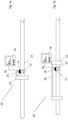
- Figure 1a and 1b illustrates an ultrasonic testing apparatus configured to inspect a splice in a cable lead sheath.
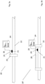
- Figure 2a and 2b illustrates an ultrasonic testing apparatus configured to inspect a section of a cable lead sheath.
- the ultrasonic testing apparatus 10 for inspection of power cable lead sheath is illustrated in different configurations. Same elements have same reference numbers in the figures.
- the ultrasonic testing apparatus 10 comprise an ultrasonic probe 11 for emitting ultrasound waves towards the power cable lead sheath 12 and recording ultrasound waves reflected from the power cable lead sheath 12, a probe guiding device 13,18 configured to move the ultrasonic probe along an inspection path, and a processing device 14 connected to the ultrasonic probe for receiving signals from the ultrasonic probe and processing the signals to provide an image representing the lead sheath along the inspection path.
- the signals are transferred through the signal cable 16 from the ultrasonic probe 11 to the processing device 14.
- the ultrasonic probe 11 is a configured to measure the lead sheath and comprises an ultrasonic transducer configured to emit waves in the ultrasound range. To transmit the waves to the lead sheath and receive the reflected waves, the ultrasonic probe 11 comprises a rubber membrane closing a chamber filled with water, gel or other suitable substance. The ultrasonic probe is in one embodiment configured to emit sound waves with a frequency of 10MHz.
- the probe guiding device 13 is a rotary probe guiding device which is configured to move the ultrasonic probe along the circumference of the lead sheath 12.
- the rotary probe guiding device comprises a fixing frame 15 which fixes the ultrasonic probe in the desired location around the lead sheath 12.
- the fixing frame is rotatable arranged in order to allow the ultrasonic probe to be rotated around the lead sheath.
- the rotary probe guiding device comprises or is connected to a motor or other driving means that causes the movement of the fixing frame and the ultrasonic probe.
- the ultrasonic testing apparatus 10 is arranged to inspect a splice 17.
- the ultrasonic probe 11 is then rotated around the complete circumference while it is operated, thus scanning the circumference and providing information regarding the thickness and shape of the splice over the circumference.
- the signals from the ultrasonic probe 11 are transmitted to the processing device 14 which processes the signals to provide an image of the cross section of the lead sheath splice.
- the ultrasonic testing apparatus 10' also is configured to inspect a splice 17, but in this embodiment, the probe guiding device 18 comprises an elongated fixing frame 19 which is arranged in parallel to the power cable during operation.
- the ultrasonic probe 11 can be moved along the fixing frame 19, thus scanning the length of the lead sheath. The ultrasonic probe will then be moved the desired length in order to inspect the area of interest.
- figure 1a and 1b may be combined to scan the lead sheath in both longitudinal and circumferential direction to map a larger area of the lead sheath.
- FIGs 2a and 2b illustrates similar embodiments of an ultrasonic testing apparatus as shown in figure 1a and 1b , but the ultrasonic testing apparatus is in these embodiments arranged to inspect a section of the lead sheath without splice.
- the ultrasonic testing apparatus 20, 20' comprise an ultrasonic probe 21 for emitting ultrasound waves towards the power cable lead sheath 22 and recording ultrasound waves reflected from the power cable lead sheath 22, a probe guiding device 23,28 configured to move the ultrasonic probe 21 along an inspection path, and a processing device 24 connected to the ultrasonic probe for receiving signals from the ultrasonic probe and processing the signals to provide an image representing the lead sheath along the inspection path.
- the signals are transferred through the signal cable 26 from the ultrasonic probe 21 to the processing device 24.
Landscapes
- Physics & Mathematics (AREA)
- Health & Medical Sciences (AREA)
- Life Sciences & Earth Sciences (AREA)
- Chemical & Material Sciences (AREA)
- Analytical Chemistry (AREA)
- Biochemistry (AREA)
- General Health & Medical Sciences (AREA)
- General Physics & Mathematics (AREA)
- Immunology (AREA)
- Pathology (AREA)
- Acoustics & Sound (AREA)
- Investigating Or Analyzing Materials By The Use Of Ultrasonic Waves (AREA)
Abstract
Description
- The invention regards an ultrasonic testing apparatus and a method for ultrasonic imaging of power cable lead sheath.
- In the manufacture of cables with lead sheathing, special attention is to be paid by the operating personnel to the quality of the lead sheath applied to the cable. It is an important aspect of cable manufacturing to inspect the lead sheath for imperfections, contaminations etc., and in particular it is important to monitor and inspect areas where lead sheath sections are spliced.
- Traditionally such inspections are performed using imaging of the lead sheath or lead sheath splice by means of a high energy Gamma-Ray or X-ray Source. The imaging resulting from such methods gives not satisfactory images of the lead sheath for interpretation of the quality of the manufactured lead sheath. It is not possible to get an image of the complete circumference of the lead sheath/lead sheath splice due to high reflectivity of the cable core. The prior art techniques are very time consuming and the radiation sources are potentially harmful for the operator, which gives high demands to the safety procedures and equipment in order to reduce risk for radiation injury for the operators.
- It is thus a need for improved inspection and testing methods.
- Ultrasonic testing (UT) is a family of non-destructive testing techniques based on the propagation of ultrasonic waves in the object or material tested. In most common UT applications, very short ultrasonic pulse-waves with center frequencies ranging from 0.1-15 MHz, and occasionally up to 50 MHz, are transmitted into materials to detect internal flaws or to characterize materials. A common example is ultrasonic thickness measurement, which tests the thickness of the test object, for example, to monitor pipework corrosion.
- Ultrasonic testing is often performed on steel and other metals and alloys, though it can also be used on concrete, wood and composites, albeit with less resolution. It is used in many industries including steel and aluminum construction, metallurgy, manufacturing, aerospace, automotive and other transportation sectors.
-
EP0045056 describes a monitoring device for monitoring lead thickness for use in a process for the production of lead cables. Measuring transducers distributed around the circumference are provided for the wall thickness of the lead jacket, for the cable length generated and the amount of lead associated therewith, which are connected by an evaluation unit to an image signal generator, the image signal generator being connected to a color image transmitter arranged at the work place and controlling it. - The device of
EP0045056 thus focuses on converting the signals from several sensors into a color image representation, which is provided directly on the lead press during the entire lead cable production process. -
GB2232250 - An object of the invention is to provide an ultrasonic testing apparatus and method for ultrasonic imaging of power cable lead sheath that with confidence can verify the quality of the lead sheath or lead sheath splice and without posing health and safety risks for the operators.
- It is a further object of the invention to provide an ultrasonic testing apparatus and method for ultrasonic imaging of power cable lead sheath that gives significantly more information about the quality of the lead sheath or lead sheath splice than prior art. This gives more confidence in determining the quality of said material.
- The object of the invention is achieved by means of the features of the patent claims.
- An ultrasonic testing apparatus for inspection of power cable lead sheath comprises in one embodiment an ultrasonic probe for emitting ultrasound waves towards the power cable lead sheath and recording ultrasound waves reflected from the power cable lead sheath, a probe guiding device configured to move the ultrasonic probe along an inspection path, and a processing device connected to the ultrasonic probe for receiving signals from the ultrasonic probe and processing the signals to provide an image representing the lead sheath along the inspection path.
- The ultrasonic probe comprises an ultrasonic transducer for generating ultrasonic waves with a desired frequency in order to provide signals that can be processed to give information related to the quality of the lead sheath such as thickness, thickness uniformity, defects, imperfections, contaminations etc. Conventional ultrasonic transducers for (non-destructive testing) commonly consist of either a single active element that both generates and receives high frequency sound waves, or two paired elements, one for transmitting and one for receiving. Phased array probes, on the other hand, typically consist of a transducer assembly with from 16 to as many as 256 small individual elements that can each be pulsed separately. These may be arranged in a strip (linear array), a ring (annular array), a circular matrix (circular array), or a more complex shape. Unlike conventional flaw detectors, phased array systems can sweep a sound beam through a range of refracted angles or along a linear path, or dynamically focus at a number of different depths, thus increasing both flexibility and capability in inspection setups. Phased-array systems can display ultrasonic data as sectorial or linear images allowing an inspector to see instantly a complete zone of the component and thus interpret data more easily.
- The Total Focusing Method (TFM) and/or Adaptive Ultrasonic Imaging Method (ATFM) imaging techniques can be applied to ultrasonic data. The data can for example be recorded from a FMC (Full Matric Capture) acquisition to produce an image in a region of the component. The FMC presents the advantage of maximizing the information available from a given array composed of N elements by sending ultrasonic energy everywhere in the component; this way potential defects can be seen from multiple directions. The FMC acquisition consists in firing each element of the array in turn and recording the information reflected/diffracted in the component on all the elements.
- In one embodiment, the ultrasonic probe comprises a rubber membrane and a closed water chamber for transmitting the ultrasound waves from the transducer to the lead sheath and to receive the reflected waves. The reflected waves are registered, and the signals generated in the ultrasonic probe are recorded and processed to provide signals representing the characteristics of the lead sheath.
- The ultrasonic probe is configured to emit waves with a wavelength adapted to lead. A suitable frequency of the sound waves is for example in the area 5-15 MHz, and is in one embodiment 10MHz.
- In one embodiment, the probe guiding device comprises a guiding control unit configured for controlling the movement of the ultrasonic probe to follow the inspection path. The guiding control unit can control to probe to measure the area of interest, such as the complete circumference of the lead sheath and a predetermined length. To achieve this, the probe guiding apparatus will move the probe according to the individual needs. The measurements can be done with a resolution set by the operator and/or adapted to the specific use, ie. the guiding control unit will control the movement accordingly. A resolution of 1mm is for example achieved by moving the ultrasonic probe 1mm between each operation of the probe.
- The ultrasonic testing apparatus may comprise an ultrasonic control unit connected to the ultrasonic probe for controlling the ultrasound waves emitted from the ultrasonic probe. The ultrasonic control unit may be in communication with the probe guiding device for coordination of the movement of the ultrasonic probe and the emittance of ultrasound waves.
- The invention will now be described in more detail by means of example and by reference to the accompanying figures.
-
Figure 1a and 1b illustrates an ultrasonic testing apparatus configured to inspect a splice in a cable lead sheath. -
Figure 2a and 2b illustrates an ultrasonic testing apparatus configured to inspect a section of a cable lead sheath. - In the figures an
ultrasonic testing apparatus 10 for inspection of power cable lead sheath is illustrated in different configurations. Same elements have same reference numbers in the figures. Theultrasonic testing apparatus 10 comprise anultrasonic probe 11 for emitting ultrasound waves towards the powercable lead sheath 12 and recording ultrasound waves reflected from the powercable lead sheath 12, aprobe guiding device processing device 14 connected to the ultrasonic probe for receiving signals from the ultrasonic probe and processing the signals to provide an image representing the lead sheath along the inspection path. The signals are transferred through thesignal cable 16 from theultrasonic probe 11 to theprocessing device 14. - The
ultrasonic probe 11 is a configured to measure the lead sheath and comprises an ultrasonic transducer configured to emit waves in the ultrasound range. To transmit the waves to the lead sheath and receive the reflected waves, theultrasonic probe 11 comprises a rubber membrane closing a chamber filled with water, gel or other suitable substance. The ultrasonic probe is in one embodiment configured to emit sound waves with a frequency of 10MHz. - In the example of
figure 1a theprobe guiding device 13 is a rotary probe guiding device which is configured to move the ultrasonic probe along the circumference of thelead sheath 12. The rotary probe guiding device comprises afixing frame 15 which fixes the ultrasonic probe in the desired location around thelead sheath 12. The fixing frame is rotatable arranged in order to allow the ultrasonic probe to be rotated around the lead sheath. - The rotary probe guiding device comprises or is connected to a motor or other driving means that causes the movement of the fixing frame and the ultrasonic probe.
- In this example the
ultrasonic testing apparatus 10 is arranged to inspect asplice 17. Theultrasonic probe 11 is then rotated around the complete circumference while it is operated, thus scanning the circumference and providing information regarding the thickness and shape of the splice over the circumference. The signals from theultrasonic probe 11 are transmitted to theprocessing device 14 which processes the signals to provide an image of the cross section of the lead sheath splice. - In the example of
figure 1b , the ultrasonic testing apparatus 10' also is configured to inspect asplice 17, but in this embodiment, theprobe guiding device 18 comprises anelongated fixing frame 19 which is arranged in parallel to the power cable during operation. Theultrasonic probe 11 can be moved along the fixingframe 19, thus scanning the length of the lead sheath. The ultrasonic probe will then be moved the desired length in order to inspect the area of interest. - The embodiments of
figure 1a and 1b may be combined to scan the lead sheath in both longitudinal and circumferential direction to map a larger area of the lead sheath. -
Figures 2a and 2b illustrates similar embodiments of an ultrasonic testing apparatus as shown infigure 1a and 1b , but the ultrasonic testing apparatus is in these embodiments arranged to inspect a section of the lead sheath without splice. - The
ultrasonic testing apparatus 20, 20' comprise anultrasonic probe 21 for emitting ultrasound waves towards the powercable lead sheath 22 and recording ultrasound waves reflected from the powercable lead sheath 22, aprobe guiding device ultrasonic probe 21 along an inspection path, and aprocessing device 24 connected to the ultrasonic probe for receiving signals from the ultrasonic probe and processing the signals to provide an image representing the lead sheath along the inspection path. The signals are transferred through thesignal cable 26 from theultrasonic probe 21 to theprocessing device 24.
Claims (13)
- Ultrasonic testing apparatus (10) for inspection of power cable lead sheath (12), comprising- an ultrasonic probe (11) for emitting ultrasound waves towards the power cable lead sheath (12) and recording ultrasound waves reflected from the power cable lead sheath (12),- a probe guiding device (13) configured to move the ultrasonic probe (11) along an inspection path, and- a processing device (14) connected to the ultrasonic probe (11) for receiving signals from the ultrasonic probe (11) and processing the signals to provide an image representing the lead sheath (12) along the inspection path.
- Ultrasonic testing apparatus (10) according to claim 1, where the ultrasonic probe (11) comprises a rubber membrane and a closed water chamber for transmitting the ultrasound waves to the lead sheath (12).
- Ultrasonic testing apparatus (10) according to one of the previous claims, where the ultrasonic probe (11) is configured to emit waves with a wavelength adapted to lead.
- Ultrasonic testing apparatus (10) according to one of the previous claims, where the probe guiding device (13) comprises a control unit configured for controlling the movement of the ultrasonic probe (11) to follow the inspection path.
- Ultrasonic testing apparatus (10) according to one of the previous claims, comprising an ultrasonic control unit connected to the ultrasonic probe (11) for controlling the ultrasound waves emitted from the ultrasonic probe (11).
- Ultrasonic testing apparatus (10) according to one of the previous claims, where the ultrasonic control unit is in communication with the probe guiding device (13) for coordination of the movement of the ultrasonic probe (11) and the emittance of ultrasound waves.
- Ultrasonic testing apparatus (10) according to one the previous claims, where the probe guiding device (13) is configured to move the ultrasonic probe (11) the complete circumference of the lead sheath (12) and a predetermined length.
- Method for ultrasonic imaging of power cable lead sheath comprising- emitting ultrasound waves towards the power cable lead sheath,- moving the ultrasonic probe along an inspection path, and- processing signals reflected from the power cable lead sheath to provide an image representing the lead sheath along the inspection path.
- Method according to claim 8, where the ultrasonic waves are emitted with a wavelength adapted to lead.
- Method according to claim 8 or 9, comprising controlling the movement of the ultrasonic probe to follow the inspection path.
- Method according to one of claims 8 to 10, comprising controlling the ultrasound waves emitted from the ultrasonic probe.
- Method according to one of claims 9 to 11, coordinating the movement of the ultrasonic probe and the emittance of ultrasound waves.
- Method according to one of claims 9-12, where the signals reflected from the power cable lead sheath are processed by using Phased Array Ultrasonic Testing (PAUT) or Adaptive Total focusing Method (ATFM) techniques.
Priority Applications (2)
| Application Number | Priority Date | Filing Date | Title |
|---|---|---|---|
| EP20306007.4A EP3967971B1 (en) | 2020-09-10 | 2020-09-10 | Non-destructive testing apparatus and method |
| ES20306007T ES3047484T3 (en) | 2020-09-10 | 2020-09-10 | Non-destructive testing apparatus and method |
Applications Claiming Priority (1)
| Application Number | Priority Date | Filing Date | Title |
|---|---|---|---|
| EP20306007.4A EP3967971B1 (en) | 2020-09-10 | 2020-09-10 | Non-destructive testing apparatus and method |
Publications (3)
| Publication Number | Publication Date |
|---|---|
| EP3967971A1 true EP3967971A1 (en) | 2022-03-16 |
| EP3967971C0 EP3967971C0 (en) | 2025-08-13 |
| EP3967971B1 EP3967971B1 (en) | 2025-08-13 |
Family
ID=72615783
Family Applications (1)
| Application Number | Title | Priority Date | Filing Date |
|---|---|---|---|
| EP20306007.4A Active EP3967971B1 (en) | 2020-09-10 | 2020-09-10 | Non-destructive testing apparatus and method |
Country Status (2)
| Country | Link |
|---|---|
| EP (1) | EP3967971B1 (en) |
| ES (1) | ES3047484T3 (en) |
Cited By (1)
| Publication number | Priority date | Publication date | Assignee | Title |
|---|---|---|---|---|
| CN116183716A (en) * | 2022-12-31 | 2023-05-30 | 国网北京市电力公司 | Detection method, device, storage medium and equipment for cable protective gear |
Citations (10)
| Publication number | Priority date | Publication date | Assignee | Title |
|---|---|---|---|---|
| US3921440A (en) * | 1975-01-02 | 1975-11-25 | Air Prod & Chem | Ultrasonic pipe testing system |
| EP0045056A2 (en) | 1980-07-23 | 1982-02-03 | WIENER KABEL- UND METALLWERKE Gesellschaft m.b.H. | Control device for the production process of lead cables |
| GB2232250A (en) | 1989-04-05 | 1990-12-05 | Bicc Plc | Ultrasonic testing of mineral insulated cable during manufacture |
| JPH09304358A (en) * | 1996-05-10 | 1997-11-28 | Sumitomo Electric Ind Ltd | Defect detection method for lead sheath pipe for electric wire |
| WO2001096853A1 (en) * | 2000-06-16 | 2001-12-20 | Abb Ab | A method of measuring topography in an interface and use of the method for a high-voltage cable |
| US20140076053A1 (en) * | 2011-03-31 | 2014-03-20 | Atomic Energy Of Canada Limited | Profiling tool for determining material thickness for inspection sites having complex topography |
| US20140345384A1 (en) * | 2013-05-22 | 2014-11-27 | Veracity Technology Solutions, Llc | Generator Retaining Ring Scanning Robot |
| EP3239706A1 (en) * | 2016-04-29 | 2017-11-01 | Fraunhofer-Gesellschaft zur Förderung der angewandten Forschung e.V. | Apparatus and method for inspecting an object using ultrasonic waves in the field of material testing |
| US20190079031A1 (en) * | 2017-09-11 | 2019-03-14 | The Boeing Company | X-Ray Inspection System for Pipes |
| US20190195829A1 (en) * | 2013-12-17 | 2019-06-27 | Ontario Power Generation, Inc. | Ultrasound inspection |
-
2020
- 2020-09-10 EP EP20306007.4A patent/EP3967971B1/en active Active
- 2020-09-10 ES ES20306007T patent/ES3047484T3/en active Active
Patent Citations (10)
| Publication number | Priority date | Publication date | Assignee | Title |
|---|---|---|---|---|
| US3921440A (en) * | 1975-01-02 | 1975-11-25 | Air Prod & Chem | Ultrasonic pipe testing system |
| EP0045056A2 (en) | 1980-07-23 | 1982-02-03 | WIENER KABEL- UND METALLWERKE Gesellschaft m.b.H. | Control device for the production process of lead cables |
| GB2232250A (en) | 1989-04-05 | 1990-12-05 | Bicc Plc | Ultrasonic testing of mineral insulated cable during manufacture |
| JPH09304358A (en) * | 1996-05-10 | 1997-11-28 | Sumitomo Electric Ind Ltd | Defect detection method for lead sheath pipe for electric wire |
| WO2001096853A1 (en) * | 2000-06-16 | 2001-12-20 | Abb Ab | A method of measuring topography in an interface and use of the method for a high-voltage cable |
| US20140076053A1 (en) * | 2011-03-31 | 2014-03-20 | Atomic Energy Of Canada Limited | Profiling tool for determining material thickness for inspection sites having complex topography |
| US20140345384A1 (en) * | 2013-05-22 | 2014-11-27 | Veracity Technology Solutions, Llc | Generator Retaining Ring Scanning Robot |
| US20190195829A1 (en) * | 2013-12-17 | 2019-06-27 | Ontario Power Generation, Inc. | Ultrasound inspection |
| EP3239706A1 (en) * | 2016-04-29 | 2017-11-01 | Fraunhofer-Gesellschaft zur Förderung der angewandten Forschung e.V. | Apparatus and method for inspecting an object using ultrasonic waves in the field of material testing |
| US20190079031A1 (en) * | 2017-09-11 | 2019-03-14 | The Boeing Company | X-Ray Inspection System for Pipes |
Cited By (1)
| Publication number | Priority date | Publication date | Assignee | Title |
|---|---|---|---|---|
| CN116183716A (en) * | 2022-12-31 | 2023-05-30 | 国网北京市电力公司 | Detection method, device, storage medium and equipment for cable protective gear |
Also Published As
| Publication number | Publication date |
|---|---|
| EP3967971C0 (en) | 2025-08-13 |
| ES3047484T3 (en) | 2025-12-03 |
| EP3967971B1 (en) | 2025-08-13 |
Similar Documents
| Publication | Publication Date | Title |
|---|---|---|
| EP2844995B1 (en) | System and method for industrial ultrasonic inspection using phased array probe and distance-gain-size flaw sizing | |
| CA2594965C (en) | Ultrasound phased array devices and methods for use with stainless steel | |
| US7900517B2 (en) | System and method for inspecting a pipeline with ultrasound | |
| CA2759472C (en) | Apparatus and method for measuring material thickness | |
| CN103080741A (en) | Phased array ultrasonic inspection system for turbine and generator rotor bore | |
| US11415554B2 (en) | Ultrasonic inspection method | |
| US20090249879A1 (en) | Inspection systems and methods for detection of material property anomalies | |
| US4760737A (en) | Procedure for flaw detection in cast stainless steel | |
| Yadav et al. | A comparative study of ultrasonic contact and immersion method for dimensional measurements | |
| CA3092172A1 (en) | Method and device for testing a component non-destructively | |
| EP3967971B1 (en) | Non-destructive testing apparatus and method | |
| JP2011529170A (en) | Improved ultrasonic non-destructive inspection using coupling check | |
| CN110487912A (en) | A self-focusing phased array ultrasonic testing probe for in-pipe non-destructive testing | |
| JP6366676B2 (en) | Ultrasonic inspection of parts whose surface shape is unknown | |
| MacLeod et al. | Advanced nondestructive evaluation for welded joints | |
| Pugalendhi et al. | Use of Phased Array Ultrasonic Testing (PAUT) & Time Of Flight Diffraction (TOFD) in Lieu of Radiography Testing on ASME U Stamp Pressure Vessel fabrication Projects | |
| JPH05180807A (en) | Method for selecting ultrasonic-wave probe and probe selected by method thereof | |
| Wasif et al. | Eddy current array developments for remote deployment on the ITER project | |
| Martin | Ultrasonic Testing on EUROFER Welded Joints for Determination of the Minimum Detectable Flaw Size.(KIT Scientific Reports; 7543) | |
| KR102740540B1 (en) | Calibration method of focus length for test device | |
| Cheng et al. | Ultrasonic phased array linear-nonlinear fusion imaging method of microcracks in pressure equipment | |
| Lesage | Phased Array Ultrasonic Testing | |
| Oktikawati et al. | Multi-Mode Total Focusing Method (MTFM) to Detect High-Temperature Hydrogen Attack (HTHA)–A Review | |
| Martin et al. | Immersion ultrasonic testing on EUROFER welded joints for determination of the minimum detectable flaw size | |
| AKBAROV et al. | DEVELOPMENT OF TESTING USING NON-DESTRUCTIVE TESTING METHODS |
Legal Events
| Date | Code | Title | Description |
|---|---|---|---|
| PUAI | Public reference made under article 153(3) epc to a published international application that has entered the european phase |
Free format text: ORIGINAL CODE: 0009012 |
|
| STAA | Information on the status of an ep patent application or granted ep patent |
Free format text: STATUS: THE APPLICATION HAS BEEN PUBLISHED |
|
| AK | Designated contracting states |
Kind code of ref document: A1 Designated state(s): AL AT BE BG CH CY CZ DE DK EE ES FI FR GB GR HR HU IE IS IT LI LT LU LV MC MK MT NL NO PL PT RO RS SE SI SK SM TR |
|
| STAA | Information on the status of an ep patent application or granted ep patent |
Free format text: STATUS: REQUEST FOR EXAMINATION WAS MADE |
|
| 17P | Request for examination filed |
Effective date: 20220916 |
|
| RBV | Designated contracting states (corrected) |
Designated state(s): AL AT BE BG CH CY CZ DE DK EE ES FI FR GB GR HR HU IE IS IT LI LT LU LV MC MK MT NL NO PL PT RO RS SE SI SK SM TR |
|
| STAA | Information on the status of an ep patent application or granted ep patent |
Free format text: STATUS: EXAMINATION IS IN PROGRESS |
|
| 17Q | First examination report despatched |
Effective date: 20240126 |
|
| REG | Reference to a national code |
Ref country code: DE Free format text: PREVIOUS MAIN CLASS: G01B0017020000 Ref country code: DE Ref legal event code: R079 Ref document number: 602020056401 Country of ref document: DE Free format text: PREVIOUS MAIN CLASS: G01B0017020000 Ipc: G01N0029060000 |
|
| GRAP | Despatch of communication of intention to grant a patent |
Free format text: ORIGINAL CODE: EPIDOSNIGR1 |
|
| STAA | Information on the status of an ep patent application or granted ep patent |
Free format text: STATUS: GRANT OF PATENT IS INTENDED |
|
| RIC1 | Information provided on ipc code assigned before grant |
Ipc: G01B 17/02 20060101ALN20250228BHEP Ipc: G01N 29/28 20060101ALI20250228BHEP Ipc: G01N 29/26 20060101ALI20250228BHEP Ipc: G01N 29/265 20060101ALI20250228BHEP Ipc: G01N 29/22 20060101ALI20250228BHEP Ipc: G01N 29/06 20060101AFI20250228BHEP |
|
| INTG | Intention to grant announced |
Effective date: 20250313 |
|
| RIN1 | Information on inventor provided before grant (corrected) |
Inventor name: JOHANSEN, BEN KRISTIAN Inventor name: SKARNES, WIDAR |
|
| GRAS | Grant fee paid |
Free format text: ORIGINAL CODE: EPIDOSNIGR3 |
|
| GRAA | (expected) grant |
Free format text: ORIGINAL CODE: 0009210 |
|
| STAA | Information on the status of an ep patent application or granted ep patent |
Free format text: STATUS: THE PATENT HAS BEEN GRANTED |
|
| AK | Designated contracting states |
Kind code of ref document: B1 Designated state(s): AL AT BE BG CH CY CZ DE DK EE ES FI FR GB GR HR HU IE IS IT LI LT LU LV MC MK MT NL NO PL PT RO RS SE SI SK SM TR |
|
| REG | Reference to a national code |
Ref country code: GB Ref legal event code: FG4D |
|
| REG | Reference to a national code |
Ref country code: CH Ref legal event code: EP |
|
| REG | Reference to a national code |
Ref country code: DE Ref legal event code: R096 Ref document number: 602020056401 Country of ref document: DE |
|
| REG | Reference to a national code |
Ref country code: IE Ref legal event code: FG4D |
|
| U01 | Request for unitary effect filed |
Effective date: 20250911 |
|
| U07 | Unitary effect registered |
Designated state(s): AT BE BG DE DK EE FI FR IT LT LU LV MT NL PT RO SE SI Effective date: 20250918 |
|
| U20 | Renewal fee for the european patent with unitary effect paid |
Year of fee payment: 6 Effective date: 20250916 |
|
| REG | Reference to a national code |
Ref country code: ES Ref legal event code: FG2A Ref document number: 3047484 Country of ref document: ES Kind code of ref document: T3 Effective date: 20251203 |
|
| PG25 | Lapsed in a contracting state [announced via postgrant information from national office to epo] |
Ref country code: IS Free format text: LAPSE BECAUSE OF FAILURE TO SUBMIT A TRANSLATION OF THE DESCRIPTION OR TO PAY THE FEE WITHIN THE PRESCRIBED TIME-LIMIT Effective date: 20251213 |
|
| PGFP | Annual fee paid to national office [announced via postgrant information from national office to epo] |
Ref country code: GB Payment date: 20251014 Year of fee payment: 6 |
|
| PGFP | Annual fee paid to national office [announced via postgrant information from national office to epo] |
Ref country code: NO Payment date: 20251013 Year of fee payment: 6 |
|
| PG25 | Lapsed in a contracting state [announced via postgrant information from national office to epo] |
Ref country code: HR Free format text: LAPSE BECAUSE OF FAILURE TO SUBMIT A TRANSLATION OF THE DESCRIPTION OR TO PAY THE FEE WITHIN THE PRESCRIBED TIME-LIMIT Effective date: 20250813 |
|
| PG25 | Lapsed in a contracting state [announced via postgrant information from national office to epo] |
Ref country code: GR Free format text: LAPSE BECAUSE OF FAILURE TO SUBMIT A TRANSLATION OF THE DESCRIPTION OR TO PAY THE FEE WITHIN THE PRESCRIBED TIME-LIMIT Effective date: 20251114 |
|
| PG25 | Lapsed in a contracting state [announced via postgrant information from national office to epo] |
Ref country code: PL Free format text: LAPSE BECAUSE OF FAILURE TO SUBMIT A TRANSLATION OF THE DESCRIPTION OR TO PAY THE FEE WITHIN THE PRESCRIBED TIME-LIMIT Effective date: 20250813 |
|
| PG25 | Lapsed in a contracting state [announced via postgrant information from national office to epo] |
Ref country code: RS Free format text: LAPSE BECAUSE OF FAILURE TO SUBMIT A TRANSLATION OF THE DESCRIPTION OR TO PAY THE FEE WITHIN THE PRESCRIBED TIME-LIMIT Effective date: 20251113 |
|
| PGFP | Annual fee paid to national office [announced via postgrant information from national office to epo] |
Ref country code: ES Payment date: 20251027 Year of fee payment: 6 |
|
| PG25 | Lapsed in a contracting state [announced via postgrant information from national office to epo] |
Ref country code: SM Free format text: LAPSE BECAUSE OF FAILURE TO SUBMIT A TRANSLATION OF THE DESCRIPTION OR TO PAY THE FEE WITHIN THE PRESCRIBED TIME-LIMIT Effective date: 20250813 |
|
| PG25 | Lapsed in a contracting state [announced via postgrant information from national office to epo] |
Ref country code: CZ Free format text: LAPSE BECAUSE OF FAILURE TO SUBMIT A TRANSLATION OF THE DESCRIPTION OR TO PAY THE FEE WITHIN THE PRESCRIBED TIME-LIMIT Effective date: 20250813 |
|
| PG25 | Lapsed in a contracting state [announced via postgrant information from national office to epo] |
Ref country code: SK Free format text: LAPSE BECAUSE OF FAILURE TO SUBMIT A TRANSLATION OF THE DESCRIPTION OR TO PAY THE FEE WITHIN THE PRESCRIBED TIME-LIMIT Effective date: 20250813 |
|
| REG | Reference to a national code |
Ref country code: CH Ref legal event code: H13 Free format text: ST27 STATUS EVENT CODE: U-0-0-H10-H13 (AS PROVIDED BY THE NATIONAL OFFICE) Effective date: 20260504 |
|
| PLBE | No opposition filed within time limit |
Free format text: ORIGINAL CODE: 0009261 |
|
| STAA | Information on the status of an ep patent application or granted ep patent |
Free format text: STATUS: NO OPPOSITION FILED WITHIN TIME LIMIT |
|
| REG | Reference to a national code |
Ref country code: CH Ref legal event code: L10 Free format text: ST27 STATUS EVENT CODE: U-0-0-L10-L00 (AS PROVIDED BY THE NATIONAL OFFICE) Effective date: 20260624 |
|
| PG25 | Lapsed in a contracting state [announced via postgrant information from national office to epo] |
Ref country code: MC Free format text: LAPSE BECAUSE OF FAILURE TO SUBMIT A TRANSLATION OF THE DESCRIPTION OR TO PAY THE FEE WITHIN THE PRESCRIBED TIME-LIMIT Effective date: 20250813 |
|
| PG25 | Lapsed in a contracting state [announced via postgrant information from national office to epo] |
Ref country code: IE Free format text: LAPSE BECAUSE OF NON-PAYMENT OF DUE FEES Effective date: 20250910 Ref country code: CH Free format text: LAPSE BECAUSE OF NON-PAYMENT OF DUE FEES Effective date: 20250930 |
|
| 26N | No opposition filed |
Effective date: 20260515 |