EP3967964A1 - Connection for the upper receiver part and the lower receiver part of a firearm - Google Patents
Connection for the upper receiver part and the lower receiver part of a firearm Download PDFInfo
- Publication number
- EP3967964A1 EP3967964A1 EP20195503.6A EP20195503A EP3967964A1 EP 3967964 A1 EP3967964 A1 EP 3967964A1 EP 20195503 A EP20195503 A EP 20195503A EP 3967964 A1 EP3967964 A1 EP 3967964A1
- Authority
- EP
- European Patent Office
- Prior art keywords
- receiver
- pivot pin
- receiver part
- hole
- firearm according
- Prior art date
- Legal status (The legal status is an assumption and is not a legal conclusion. Google has not performed a legal analysis and makes no representation as to the accuracy of the status listed.)
- Granted
Links
Images



Classifications
-
- F—MECHANICAL ENGINEERING; LIGHTING; HEATING; WEAPONS; BLASTING
- F41—WEAPONS
- F41A—FUNCTIONAL FEATURES OR DETAILS COMMON TO BOTH SMALLARMS AND ORDNANCE, e.g. CANNONS; MOUNTINGS FOR SMALLARMS OR ORDNANCE
- F41A3/00—Breech mechanisms, e.g. locks
- F41A3/64—Mounting of breech-blocks; Accessories for breech-blocks or breech-block mountings
- F41A3/66—Breech housings or frames; Receivers
-
- F—MECHANICAL ENGINEERING; LIGHTING; HEATING; WEAPONS; BLASTING
- F41—WEAPONS
- F41A—FUNCTIONAL FEATURES OR DETAILS COMMON TO BOTH SMALLARMS AND ORDNANCE, e.g. CANNONS; MOUNTINGS FOR SMALLARMS OR ORDNANCE
- F41A3/00—Breech mechanisms, e.g. locks
- F41A3/64—Mounting of breech-blocks; Accessories for breech-blocks or breech-block mountings
-
- F—MECHANICAL ENGINEERING; LIGHTING; HEATING; WEAPONS; BLASTING
- F41—WEAPONS
- F41A—FUNCTIONAL FEATURES OR DETAILS COMMON TO BOTH SMALLARMS AND ORDNANCE, e.g. CANNONS; MOUNTINGS FOR SMALLARMS OR ORDNANCE
- F41A3/00—Breech mechanisms, e.g. locks
- F41A3/64—Mounting of breech-blocks; Accessories for breech-blocks or breech-block mountings
- F41A3/68—Bolt stops, i.e. means for limiting bolt opening movement
Definitions
- the invention relates to a firearm having an upper receiver part, usually called the "upper,” and a lower receiver part, usually called the “lower,” which are detachably connected to each other, and in this case the connection of the two parts, according to the preamble of claim 1.
- Firearms with a multi-part receiver have been known for a long time. Examples include the types M4 / M16 / AR15 or H&K G3, and their derivatives.
- the upper receiver part is connected to the lower receiver part by means of pins which run normal to the central plane of the firearm.
- the upper receiver part and the lower receiver part are inserted into each other during assembly; corresponding holes are provided in both parts, such that a front pin (also known as a pivot pin) and a rear pin (also known as a takedown pin) can be inserted, thereby producing the receiver connection.
- the upper receiver part By removing the rear pin, the upper receiver part can be opened about the axis of the front pin - hence the term "pivot pin.” In the open state, the breech is accessible and the firearm can be cleaned without completely disassembling it. To completely disassemble the firearm, the front pin must also be removed.
- EP 2 045 560 discloses the use of a type of pseudo-joint as a pivot pin, and a connecting device made of elastomer material at the rear end of the firearm. This soft connection cannot cope with the harsh operating conditions in the field; in practice this design does not occur.
- a connecting mechanism is formed which comprises at least one pivot pin, a receiver pivot pin hole, and a connector element, and which works together with projections or recesses of the upper receiver part or lower receiver part of complementary shape.
- the receiver pivot pin hole corresponds to a bore and can be formed on the upper receiver part (upper) and/or the lower receiver part (lower), and has an axis that is normal to the weapon median plane.
- the connector element has at least one hole and one slotted hole, the axes of which are normal to the weapon median plane.
- the pivot pin is designed to work together with the receiver pivot pin hole and the connector element, the pivot pin reaching at least through the lower (and/or upper) and at least through the slotted hole and the hole, wherein the slotted hole has its longitudinal extension, in the closed state, parallel to the barrel axis.
- Regions of complementary shape namely at least one protrusion and/or one recess, are formed on the upper and the lower in such a way that they are in contact with each other (and prevent movement between the upper and lower in the weapon median plane, and normal to the barrel axis) when the pin is situated in an end region of the slotted hole, and in such a way that they are spaced from each other (and allow a movement between the upper and the lower in the weapon median plane, and normal to the barrel axis) when the pin is situated in the other end region of the slotted hole.
- receiver pivot pin hole such as the receiver pivot pin hole, connector element, protrusion and recess
- connector element such as the connector element, protrusion and recess
- protrusion and recess can, depending on requirements, be arranged by a person skilled in the art on the upper receiver part and/or the lower receiver part in order to work together in the manner according to the invention.
- the invention is also suitable for pistols, in particular so-called “modularly constructed” pistols, but is explained below with reference to a carbine, such as the grip, the barrel, various safeties, the magazine well, or the magazine feed or shaft are likewise not explained in more detail here, since these do not concern the core of the invention, and a person skilled in the art, with knowledge of the invention, can simply make modifications based on his special technical knowledge, if necessary or desired at all.
- the invention can be used not only with newly built and/or newly designed firearms, but can also be implemented by retrofit kits or conversion kits, the invention also and generally comprises a multi-part connecting mechanism which comprises the pivot pin, the receiver pivot pin hole with its axis normal to the weapon median plane, a connector element with the hole and the slotted hole with axes normal to the weapon median plane, the protrusion running in the direction of the barrel axis and the recess which is complementary in shape and function.
- These elements can be fitted in a suitable manner on the upper and the lower, but they can also be designed to be entirely or partially integral with the upper / lower.
- the firearm has a weapon median plane going through the barrel axis and oriented vertically, which substantially forms a plane of symmetry; the barrel has a barrel axis that is referenced in the following for further orientation.
- the terms "front,” “rear,” “above,” “below” and so on are used in the generally accepted form and with reference to the object in its usual use position. This means that, for the firearm, the mouth of the barrel is “at the front,” that the breech is moved “rearward” by the explosive gas, etc. Transverse to a direction substantially means a direction which is rotated by 90° thereto.
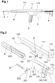
- Fig. 1 schematically illustrates a firearm having a barrel 1, grip 2, magazine 3, stock 4, handguard 41 and receiver 11, which comprises the upper receiver part 111 and the lower receiver part 112, and shows the barrel axis 5 with a dashed line.
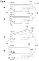
- Fig. 2 and 3a show exemplary exploded views of an embodiment of the invention.
- the connection for the receiver 11 comprises the upper receiver part 111 and the lower receiver part 112, connector element 21 with hole 22 (initially and variously also referred to below as a bore) and slotted hole 23, pivot pin 24, and receiver pivot pin hole 12, as well as a protrusion 131 and recess 141, which are designed to be complementary to each other in shape and function.
- the protrusion 131 has a rear stop surface 132 on the end section 133 and is attached to the upper receiver part 111.
- the recess 141 which is complementary in shape and function, on the receiver end section 143 has a receiver counter surface 142 and, in the design shown, is formed on the lower receiver part 112. In the closed state (when the firearm is ready for use), the protrusion 131 lies in the recess 141, and the rear stop surface 132 lies directly on the receiver counter surface 142.
- the protrusion 131 and the recess 141 can be designed in numerous shapes that deviate from the illustration shown, for example cylindrical, stepped, toothed shapes, etc.
- the protrusion 131 can also be formed on the lower receiver part 112, and the recess 141 can be formed on the upper receiver part 111.
- the connector element 21 is mounted in the upper or formed in one piece (integrally) with it; it has a hole 22 - cut out of a section called the "stud" 225, which in the assembled state runs substantially parallel to the weapon median plane 6 (shown as a dashed line in Fig. 5a ) - with an axis normal to the weapon median plane 6, and has - on a section which in the assembled state also runs substantially parallel to the weapon median plane 6, called the "lug" 235 - a slotted hole 23, the longitudinal extension of which, in the assembled state, runs parallel to the barrel axis 5.
- the rotary-sliding movement of the two parts relative to each other is made possible together with the receiver pivot pin hole 12 in the lower and the pivot pin 24.
- the handguard 41 is shown with a lock 42. On its front end (in the longitudinal direction), the handguard 41 completely surrounds the barrel; on the rear end, it is cut out at the top and has guide rails 451 on both sides, which are complementary in shape to the grooves 151 formed on both sides of the upper receiver part 111. To connect the handguard 41 to the upper receiver part 111, the handguard 41 and the upper receiver part 111 are inserted into each other in such a way that the grooves 151 receive the guide rails 451, until a front stop surface 152 strikes a mating surface 452 of the handguard 41.
- the handguard 41 Due to the interaction of the guide rails 451 and the grooves 151, the handguard 41 is secured to the upper receiver part 111 against unwanted movement transverse to the barrel axis 5, and is secured against unwanted movement in the direction of the barrel axis 5 on the one hand by the interaction between the front stop surface 152 and the mating surface 452, and on the other hand by the lock 42 together with the pivot pin 24 (see Fig. 8c and d ).
- one or more stop surfaces can be formed - for example, step-shaped, surfaces with interruptions, etc.
- a handguard 41 instead of a handguard 41, other add-on parts such as a grenade launcher can also be secured by means of a lock 42.
- Fig. 2 and 3a also show an abutment 252 which is fastened in the lower 112 with a retaining pin 252 and which forms the actual guides for the pivot pin 24 in the lower; it is explained in detail with reference to Fig. 9 .
- the pivot pin 24 can be a smooth, cylindrical, and in particular circular-cylindrical round pin; in the embodiment shown, the pivot pin 24 is designed having a head 244 and body 245 and a three-part cam 241 and detents 246 on the body 245 ( Fig. 8a and b ).
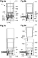
- Fig. 4a -d each show a detail of the receiver 11 with the upper receiver part 111 and the lower receiver part 112, in a lateral plan view.
- Fig. 4a shows the receiver 11 in the closed state (closed position).
- Fig. 4b shows the receiver 11 in the unlocked state (unlocked position).
- the protrusion 131 is pushed completely out of the recess 141 in the running direction, and the end section 133 is thus spatially separated from the receiver end section 143.
- Fig. 4c shows the receiver in the broken state (tilted position).
- the upper receiver part is tilted out of the lower receiver part about the pivot pin, which acts as the axis of rotation (here without reference number).
- Fig. 4d shows the receiver 11 in the completely disassembled state, as it can be reached after removing the pivot pin:
- the upper receiver part 111 is completely separated from the lower receiver part 112 (separated position).
- Fig. 5a-d show the cross-sections of the receiver in the positions according to Fig. 4a-d , each in the section plane "Vn":
- Fig. 5a shows the closed position.
- the upper receiver part 111 and the lower receiver part 112 lie one inside the other, the upper and lower guiding surfaces 161 and 162 lie against other.
- the pivot pin 24 is situated completely inside the receiver 11 and protrudes through the receiver pivot pin hole 12, the hole 22 formed on the stud 225 of the locking element 21 (clearly visible in Fig. 2 ), the slotted hole 23 formed on the lug 235 of the connector element 21 (see also Fig. 9b or Fig. 3 ), and the abutment pivot pin hole 256 (a hole, so-identified for differentiation) of the abutment 251.
- the pivot pin 24 has a cam 241 with detents, and is held in position by means of a spring-loaded plunger 242, 243, as will be explained below.
- the stud 225 lies axially in the plane of the pivot pin 24.
- Fig. 5b shows the unlocked position.
- the pivot pin 24 is partially pulled out of the receiver 11 along its longitudinal axis, and releases part of the receiver pivot pin hole 12, part of the abutment pivot pin hole 256, and also the hollow 254 and the hole 22.
- the movement of the pivot pin 24 is limited by the cam 241.
- the upper receiver part 111 and the lower receiver part 112 are displaced relative to each other parallel to the barrel axis 5, as compared to the closed position.
- the movement along the barrel axis 5 is limited by the interaction of the pivot pin 24 with the slotted hole 23. Tilting about the pivot pin 24 is not yet possible. This unlocking movement can be illustrated by comparing Fig. 2 and Fig. 7b .
- the tilted position is shown in Fig. 5c ; this position is reached by rotating (pivoting) the upper receiver part 111 relative to the lower receiver part 112, with the longitudinal axis of the pivot pin 24 acting as the axis of rotation.
- Fig. 5d shows the separated position; the upper receiver part 111 and the lower receiver part 112 are now completely separated from each other and no longer connected to each other.
- the pivot pin 24 is pulled out of the receiver 11 to the maximum extent along the third part of the cam, but is secured by a spring-loaded plunger 242, 243 engaging in a detent 246 ( Fig. 8 ), to prevent it from falling out.
- the pivot pin 24 releases the lug 235 and the slot 253 ( Fig. 9 ) and no longer protrudes into the slotted hole 23. Therefore, the upper receiver part can be completely separated from the lower receiver part.
- Fig. 6a -d show longitudinal sections of the receiver in the weapon median plane 6, in the positions according to Fig. 4a-d , the lower receiver part being partially cut out for better illustration.
- the movement of the upper receiver part 111 with the slotted hole 23 relative to the lower receiver part 112 by the span 234 (see also Fig. 7a ) can be seen.
- the closed position the pivot pin 24 lies in the first (front, toward the muzzle) end 231 ( Fig. 7 a) of the slotted hole 23.
- Fig. 6b the unlocked position, the upper receiver part is moved by the span 234 ( Fig. 7a ) relative to the lower receiver part in the direction of the barrel.
- the pivot pin is in the second (rear, facing away from the muzzle) end 232 ( Fig. 7a ) of the slotted hole 23.
- Fig. 6c shows the tilted position.
- the upper receiver part 111 is tilted relative to the lower receiver part 112; the longitudinal axis of the pivot pin 24 represents the axis of rotation, and the position of the pivot pin 24 is freely movable within the slotted hole 23.
- the slotted hole 23 of the connector element 21 is shown in a detailed view.
- the slotted hole 23 is an elongated bore with a semicircular first end 231 and a semicircular second end 232, and has a width (diameter) 233 that corresponds to the diameter of the first and second ends 231 and 232, and also at least substantially to the diameter of the receiver pivot pin hole 12 and to the diameter of the hole 22.
- the span 234 of the slotted hole 23 corresponds to the distance between the two center points of the two semicircles of the first and second ends 231 and 232, and must be at least as large (greater in practice) as the length 143 of the axial overlap 134 of the two receiver parts ( Fig.
- the pivot pin 24 should have "air" in front of the end position in order to reliably leave the axial contact between the two receiver parts to the stop surface 132 and the counter surface 142, and the two receiver parts should come free during axial displacement, at least right before the pivot pin reaches the other end position in the slotted hole, in order to reliably compensate for tolerances, thermal expansion, wear, etc.
- Fig. 7b shows the protrusion 131 on the upper receiver part 111 and the protrusion length 134.
- the protrusion length 134 of the protrusion 131 is less than the span 234 of the slotted hole 23.
- the protrusion length 134 corresponds to 0.5 to 0.95 times the span 234.
- Fig. 8a and b show a preferred development of the pivot pin 24, with the head 244 and body 245, as well as with the cam 241 with detents 246, wherein the pivot pin 24 is shown rotated by 90° in Fig. 8a and 8b .
- the cam 241 can be designed with three sections, i.e., in three parts, with two parts parallel to the pin axis and one part running in the circumferential direction, which merge into each other and are thus connected to each other.
- the cam has three radially recessed detents 246 - for the closed, unlocked and separated positions.
- the pivot pin can also be designed as a bare pin (circular cylindrical, without head and cam); other shapes with, for example a linear cam with or without detent and with or without loss protection, are also possible.
- the cam can have a clearly defined stop point during the opening and closing. However, in addition, it can also be made flat so that it rotates automatically when the pivot pin is pressed. Designs with different cams for moving the pivot pin 24 in and out can also be contemplated.
- the detent 246 cooperates with the spring-loaded plunger 242 and 243 shown in Fig. 9 , which is arranged in the abutment 251 in the embodiment shown, and thus allows the pivot pin 24 to be held in the closed, unlocked and separated positions and to fix it in a releasable manner. In the separated position, this also has a loss-preventing effect; the pivot pin 24 remains connected with the receiver 11.
- the plunger 242 with the spring 243 can, for example and as shown in Fig. 9 , be attached in the abutment 251. But it is also possible to attach the plunger 242 and spring 243 at another suitable location, for example in the receiver.
- Fig. 9 also shows the abutment 251 located in the lower receiver part 112, which in the multi-part embodiment shown is fixed in the receiver by means of the retaining pin 252 and abutment retaining pin holes 255, 257 ( Fig. 2 ).
- the abutment can also be formed integrally on the lower receiver part (or upper receiver part).
- the interaction of the lug 235 and the slot 253 when the upper receiver part and lower receiver part move relative to each other results in a guided and jam-free movement.
- the upper receiver part 111 and the lower receiver part 112 can be guided by their vertical overlaps on the sides with correspondingly designed upper and lower guiding surfaces 161 and 162.
- the depth and the cross-section of the cam 241 and the depth and shape of the detents 246 are such that there is no unintentional movement of the pivot pin 24 due to the action of the spring 243 on the plunger 242. Rather, intentional and desired pulling (or during assembly: also pressing) makes removal possible without tools. Since the end face of the head is preferably aligned with the outside of the firearm, pressure must first be exerted on the opposite end face during dismantling, for example with the head of a cartridge, then the head 244 can be grasped and moved at the transition to the body 245.
- Fig. 10 shows the lock 42 in detail.
- the lock 42 is connected to the handguard 41 ( Fig. 2 ), for example by means of screws (not shown).
- the molded hook 43 protrudes into the hollow 254 in the central region of the abutment 251 ( Fig. 9 ) in such a way that the notch 45, with an inner diameter substantially corresponding to the slot width 233 ( Fig. 7a ), is concentric to the receiver pivot pin hole 12 (in the lower, Fig. 2 ) and the abutment pivot pin hole 256 (in the abutment, Fig. 9 ).
- the handguard 41 is thus held in position in the closed state by the interaction of the hook 43 on the lock 42 with the pivot pin 24, and an undesired movement of the handguard in the direction of the muzzle is prevented.
- the lock 42 can be connected to the handguard 41 in a fixed manner or a manner allowing disassembly, for example by means of rivets, screws, gluing, welding, etc., or can also be formed integrally on the handguard 41.
- the hook 43 can be designed with the shape of a hook or with a functionally identical shaping, with a corresponding inner diameter, for example as an eyelet, sleeve, etc.
- FIG. 11a and 11b A preferred embodiment of the connector element 21, with a hole 22 and a slotted hole 23, is shown in Fig. 11a and 11b . It comprises the already-described lug 235 on which the slotted hole 23 is formed, and the stud 225 with the hole 22.
- Fig. 11b shows a side view
- Fig. 11a shows a longitudinal section along the slotted hole median plane (dashed line in Fig. 11a ).
- FIG. 12 a variant worked from the solid piece is shown in longitudinal section in Fig. 12 , wherein the hollow 254 used to accommodate the lock 42 is dispensed with in this variant.
- the slotted hole (or the connector element 21) does not have to be provided in the upper, but can instead be formed in the lower, which then also has a hole matching the longitudinal extension of the slotted hole; the pin is then (apart from rotation and axial displacement) fixedly arranged in the upper and executes the longitudinal movement with it.
- the invention relates to a firearm having a weapon median plane 6, an upper receiver part 111 with a barrel 1 with a barrel axis 5, and a lower receiver part 112, which are detachably connected to each other, the connection comprising at least one pivot pin 24, around the axis of which, normal to the weapon median plane, the two receiver parts 111, 112 can pivot relative to each other between a closed position, which occurs in the ready-to-fire state, and an open position, and is characterized in that
- the invention relates to the ensemble of the abutment 254, connector element 21 and pivot pin 24 for suitable installation in a firearm - be it a pistol or carbine. Whether the installation is done by screwing, riveting, gluing, or in some other way is a question that a person skilled in the art can easily decide with knowledge of the invention and the firearm to be converted.
- the invention is not limited to the illustrated and described exemplary embodiments, but can be modified and configured in various ways.
- the shown cross-sectional shapes of the mentioned receiver parts, pins, rails, recesses, etc. can be adapted to the given basic data; the lengths and the positions with respect to the receiver can also be easily adapted by a person skilled in the art with knowledge of the invention.
- equivalent designs are obvious with knowledge of the invention and can be carried out without further ado by a person skilled in the art.
- the holes 22, 23 provided there can be provided directly in the upper / lower.
- the abutment 251 can have a different shape or it can be dispensed with, and the receiver pivot pin hole 12 in the lower / upper then takes on the role of guide without the abutment pivot pin hole(s) 256.
- substantially means a deviation of up to 10% of the stated value, if physically possible, both downward and upward, otherwise only in the appropriate direction; in the case of degrees (angle and temperature), and for indications such as “parallel” or “normal,” this means ⁇ 10°.
- a “substantially constant” etc. what is meant is the technical possibility of deviation which the person skilled in the art proceeds from, and not the mathematical one.
- a “substantially L-shaped cross-section” comprises two elongated surfaces, which merge at one end into the end of the other surface, and whose longitudinal extensions are arranged at an angle of 45° to 120° to each other.
Landscapes
- Engineering & Computer Science (AREA)
- General Engineering & Computer Science (AREA)
- Component Parts Of Construction Machinery (AREA)
- Pivots And Pivotal Connections (AREA)
- Aiming, Guidance, Guns With A Light Source, Armor, Camouflage, And Targets (AREA)
- Input Circuits Of Receivers And Coupling Of Receivers And Audio Equipment (AREA)
- Structure Of Receivers (AREA)
Abstract
Description
- The invention relates to a firearm having an upper receiver part, usually called the "upper," and a lower receiver part, usually called the "lower," which are detachably connected to each other, and in this case the connection of the two parts, according to the preamble of
claim 1. - Firearms with a multi-part receiver have been known for a long time. Examples include the types M4 / M16 / AR15 or H&K G3, and their derivatives. In these firearms, the upper receiver part is connected to the lower receiver part by means of pins which run normal to the central plane of the firearm. The upper receiver part and the lower receiver part are inserted into each other during assembly; corresponding holes are provided in both parts, such that a front pin (also known as a pivot pin) and a rear pin (also known as a takedown pin) can be inserted, thereby producing the receiver connection.
- By removing the rear pin, the upper receiver part can be opened about the axis of the front pin - hence the term "pivot pin." In the open state, the breech is accessible and the firearm can be cleaned without completely disassembling it. To completely disassemble the firearm, the front pin must also be removed.
- Modifications are known, for example, from
DE 145 39 08 A1 , where a hinge is provided instead of the pivot pin, and the fixation takes place by means of a rotatable cam. Although the opening is simplified as a result, and the risk of loss is eliminated, a complete disassembly is extremely cumbersome. This, by way of example, practically prevents changing the barrel - necessarily with the upper in which it is mounted - in the field. -
EP 2 045 560 - As simple as the first arrangement may appear at first glance, it has its disadvantages: Despite various countermeasures, (both) pins are easy to lose, and significant forces - and in particular, shocks - are transmitted between the two receiver parts via the pins, such that these and the bearings are heavily loaded. Since the pins also substantially align the two parts relative to each other, all geometric changes to the pins are extremely negative due to the high load.
- It is therefore the aim of the invention to create a mechanically solid connection, which can also be easily disassembled, between the upper receiver part and the lower receiver part, in particular with only one pivot pin.
- According to the invention, these objectives are achieved by the features specified in the characterizing portion of claim 1 - in other words, in that a connecting mechanism is formed which comprises at least one pivot pin, a receiver pivot pin hole, and a connector element, and which works together with projections or recesses of the upper receiver part or lower receiver part of complementary shape. In the simplest case, the receiver pivot pin hole corresponds to a bore and can be formed on the upper receiver part (upper) and/or the lower receiver part (lower), and has an axis that is normal to the weapon median plane. The connector element has at least one hole and one slotted hole, the axes of which are normal to the weapon median plane. The pivot pin is designed to work together with the receiver pivot pin hole and the connector element, the pivot pin reaching at least through the lower (and/or upper) and at least through the slotted hole and the hole, wherein the slotted hole has its longitudinal extension, in the closed state, parallel to the barrel axis. Regions of complementary shape, namely at least one protrusion and/or one recess, are formed on the upper and the lower in such a way that they are in contact with each other (and prevent movement between the upper and lower in the weapon median plane, and normal to the barrel axis) when the pin is situated in an end region of the slotted hole, and in such a way that they are spaced from each other (and allow a movement between the upper and the lower in the weapon median plane, and normal to the barrel axis) when the pin is situated in the other end region of the slotted hole.
- The listed components, such as the receiver pivot pin hole, connector element, protrusion and recess can, depending on requirements, be arranged by a person skilled in the art on the upper receiver part and/or the lower receiver part in order to work together in the manner according to the invention.
- This enables the upper to be pivoted during assembly about the single pin, which is inserted in the slotted hole of the upper but not in its bore, until it rests on the lower; and then, possibly guided by guides, it is pushed in the direction of the barrel until the two complementary regions are in contact with each other. Then the pin located in the other end region of the slotted hole can also be pushed through (into) the bore of the upper; a stable connection is created by the combined action of the pin and the regions of complementary shape.
- Practically the only condition that the regions of complementary shape must meet is that their geometry in the direction of the barrel axis is designed so that, in the closed state: parts of the upper have a greater distance axially from the axis of the pivot pin than regions of the lower, and so that these parts of the upper are "below" the regions of the lower. Generally speaking, this can be described as "sticking" a projection of the upper into a recess of the lower in the direction of the barrel axis.
- In this way, a mechanically very strong connection is established; the regions of complementary shape, due to their dimensions, can do more for the alignment, as well as for force or torque transmission, than the two pins known in the prior art. The pin itself can advantageously, similarly to the prior art, be provided with pull-out locks, etc., but this is no longer the core of the invention.
- As in the prior art, it does not matter which further parts the upper contains besides the barrel and the firing mechanism, and it does not matter which further parts the lower contains besides the trigger mechanism, and therefore these are not explained in more detail here.
- Further components of the firearm, the invention is also suitable for pistols, in particular so-called "modularly constructed" pistols, but is explained below with reference to a carbine, such as the grip, the barrel, various safeties, the magazine well, or the magazine feed or shaft are likewise not explained in more detail here, since these do not concern the core of the invention, and a person skilled in the art, with knowledge of the invention, can simply make modifications based on his special technical knowledge, if necessary or desired at all.
- Since the invention can be used not only with newly built and/or newly designed firearms, but can also be implemented by retrofit kits or conversion kits, the invention also and generally comprises a multi-part connecting mechanism which comprises the pivot pin, the receiver pivot pin hole with its axis normal to the weapon median plane, a connector element with the hole and the slotted hole with axes normal to the weapon median plane, the protrusion running in the direction of the barrel axis and the recess which is complementary in shape and function. These elements can be fitted in a suitable manner on the upper and the lower, but they can also be designed to be entirely or partially integral with the upper / lower.
- The invention is explained in more detail in the following with reference to the drawings, in which:
-
Fig. 1 shows a simplified representation of a firearm according to the prior art; -
Fig. 2 shows a simplified exploded view of a receiver according to the invention, from the rear. -
Fig. 3a and b show a simplified exploded view of a receiver according to the invention, from the front. -
Fig. 4a-d show a plan view of a receiver section in the closed, unlocked, broken and separated positions. -
Fig. 5a-d show the cross-sections corresponding toFig. 4a-d along the longitudinal axis of the pivot pin. -
Fig. 6a-d are partially cut-out longitudinal sections corresponding toFig. 4a-d . -
Fig. 7a and b show a detailed view of the slotted hole and the protrusion. -
Fig. 8a and b show a detailed view of the pivot pin. -
Fig. 9 shows a detailed view of the abutment. -
Fig. 10 shows a detailed view of the lock. -
Fig. 11a and b show a detailed view of the connector element. -
Fig. 12 shows a cross section of an alternative embodiment of the connector element. - The terms left, right, up, down, front and back in the following always refer to the firearm from the point of view of the firearm when it is held ready to fire. The firearm has a weapon median plane going through the barrel axis and oriented vertically, which substantially forms a plane of symmetry; the barrel has a barrel axis that is referenced in the following for further orientation.
- In the description and the claims, the terms "front," "rear," "above," "below" and so on are used in the generally accepted form and with reference to the object in its usual use position. This means that, for the firearm, the mouth of the barrel is "at the front," that the breech is moved "rearward" by the explosive gas, etc. Transverse to a direction substantially means a direction which is rotated by 90° thereto.
-
Fig. 1 schematically illustrates a firearm having abarrel 1,grip 2,magazine 3,stock 4,handguard 41 andreceiver 11, which comprises theupper receiver part 111 and thelower receiver part 112, and shows thebarrel axis 5 with a dashed line. -
Fig. 2 and3a show exemplary exploded views of an embodiment of the invention. InFig. 3b , the arrangement of the components for assembly is indicated with dashed lines. The connection for thereceiver 11 comprises theupper receiver part 111 and thelower receiver part 112,connector element 21 with hole 22 (initially and variously also referred to below as a bore) and slottedhole 23,pivot pin 24, and receiverpivot pin hole 12, as well as aprotrusion 131 andrecess 141, which are designed to be complementary to each other in shape and function. - In the embodiment shown, the
protrusion 131 has arear stop surface 132 on theend section 133 and is attached to theupper receiver part 111. Therecess 141, which is complementary in shape and function, on thereceiver end section 143 has areceiver counter surface 142 and, in the design shown, is formed on thelower receiver part 112. In the closed state (when the firearm is ready for use), theprotrusion 131 lies in therecess 141, and therear stop surface 132 lies directly on thereceiver counter surface 142. A rearward power transmission from theupper receiver part 111 to thelower receiver part 112, as occurs, for example, when a shot is fired, takes place on the one hand via therear stop surface 132 and thereceiver counter surface 142, and on the other hand via thepivot pin 24, theconnector element 21, and the receiverpivot pin hole 12. - The
protrusion 131 and therecess 141 can be designed in numerous shapes that deviate from the illustration shown, for example cylindrical, stepped, toothed shapes, etc. In equivalent embodiments, theprotrusion 131 can also be formed on thelower receiver part 112, and therecess 141 can be formed on theupper receiver part 111. - The
connector element 21 is mounted in the upper or formed in one piece (integrally) with it; it has a hole 22 - cut out of a section called the "stud" 225, which in the assembled state runs substantially parallel to the weapon median plane 6 (shown as a dashed line inFig. 5a ) - with an axis normal to the weapon median plane 6, and has - on a section which in the assembled state also runs substantially parallel to the weapon median plane 6, called the "lug" 235 - a slottedhole 23, the longitudinal extension of which, in the assembled state, runs parallel to thebarrel axis 5. The rotary-sliding movement of the two parts relative to each other is made possible together with the receiverpivot pin hole 12 in the lower and thepivot pin 24. - In the embodiment shown, the
handguard 41 is shown with alock 42. On its front end (in the longitudinal direction), thehandguard 41 completely surrounds the barrel; on the rear end, it is cut out at the top and hasguide rails 451 on both sides, which are complementary in shape to thegrooves 151 formed on both sides of theupper receiver part 111. To connect thehandguard 41 to theupper receiver part 111, thehandguard 41 and theupper receiver part 111 are inserted into each other in such a way that thegrooves 151 receive theguide rails 451, until afront stop surface 152 strikes amating surface 452 of thehandguard 41. Due to the interaction of theguide rails 451 and thegrooves 151, thehandguard 41 is secured to theupper receiver part 111 against unwanted movement transverse to thebarrel axis 5, and is secured against unwanted movement in the direction of thebarrel axis 5 on the one hand by the interaction between thefront stop surface 152 and themating surface 452, and on the other hand by thelock 42 together with the pivot pin 24 (seeFig. 8c and d ). - In other embodiments, one or more stop surfaces, also with other shapes, can be formed - for example, step-shaped, surfaces with interruptions, etc.
- Furthermore, instead of a
handguard 41, other add-on parts such as a grenade launcher can also be secured by means of alock 42. -
Fig. 2 and3a also show anabutment 252 which is fastened in the lower 112 with a retainingpin 252 and which forms the actual guides for thepivot pin 24 in the lower; it is explained in detail with reference toFig. 9 . - In the simplest embodiment, the
pivot pin 24 can be a smooth, cylindrical, and in particular circular-cylindrical round pin; in the embodiment shown, thepivot pin 24 is designed having ahead 244 andbody 245 and a three-part cam 241 anddetents 246 on the body 245 (Fig. 8a and b ). -
Fig. 4a -d each show a detail of thereceiver 11 with theupper receiver part 111 and thelower receiver part 112, in a lateral plan view.Fig. 4a shows thereceiver 11 in the closed state (closed position).Fig. 4b shows thereceiver 11 in the unlocked state (unlocked position). Theprotrusion 131 is pushed completely out of therecess 141 in the running direction, and theend section 133 is thus spatially separated from thereceiver end section 143.Fig. 4c shows the receiver in the broken state (tilted position). In the embodiment shown, the upper receiver part is tilted out of the lower receiver part about the pivot pin, which acts as the axis of rotation (here without reference number). Theend section 133 is tilted upwards away from thereceiver end section 143. In this position, the breech can be removed without having to completely dismantle the firearm, and cleaning is also easy.Fig. 4d shows thereceiver 11 in the completely disassembled state, as it can be reached after removing the pivot pin: Theupper receiver part 111 is completely separated from the lower receiver part 112 (separated position).Fig. 5a-d show the cross-sections of the receiver in the positions according toFig. 4a-d , each in the section plane "Vn": -
Fig. 5a shows the closed position. Theupper receiver part 111 and thelower receiver part 112 lie one inside the other, the upper and lower guiding surfaces 161 and 162 lie against other. Thepivot pin 24 is situated completely inside thereceiver 11 and protrudes through the receiverpivot pin hole 12, thehole 22 formed on thestud 225 of the locking element 21 (clearly visible inFig. 2 ), the slottedhole 23 formed on thelug 235 of the connector element 21 (see alsoFig. 9b orFig. 3 ), and the abutment pivot pin hole 256 (a hole, so-identified for differentiation) of theabutment 251. Thepivot pin 24 has acam 241 with detents, and is held in position by means of a spring-loadedplunger stud 225 lies axially in the plane of thepivot pin 24. -
Fig. 5b shows the unlocked position. Thepivot pin 24 is partially pulled out of thereceiver 11 along its longitudinal axis, and releases part of the receiverpivot pin hole 12, part of the abutmentpivot pin hole 256, and also the hollow 254 and thehole 22. The movement of thepivot pin 24 is limited by thecam 241. In the unlocked position, theupper receiver part 111 and thelower receiver part 112 are displaced relative to each other parallel to thebarrel axis 5, as compared to the closed position. The movement along thebarrel axis 5 is limited by the interaction of thepivot pin 24 with the slottedhole 23. Tilting about thepivot pin 24 is not yet possible. This unlocking movement can be illustrated by comparingFig. 2 andFig. 7b . From this comparison, it can be deduced that thestud 225 visible inFig. 5a (withhole 22 through which thelocking pin 24 extends), in the unlocked position inFig. 5b , is no longer in the plane of thepivot pin 24, and accordingly can no longer be seen inFig. 5b . When the unlocking movement has been fully executed and thepivot pin 24 comes to stop in the second end 232 (Fig. 7a ) of the slottedhole 23, a tilting about the axis of thepivot pin 24 is possible. - The tilted position is shown in
Fig. 5c ; this position is reached by rotating (pivoting) theupper receiver part 111 relative to thelower receiver part 112, with the longitudinal axis of thepivot pin 24 acting as the axis of rotation. -
Fig. 5d shows the separated position; theupper receiver part 111 and thelower receiver part 112 are now completely separated from each other and no longer connected to each other. Thepivot pin 24 is pulled out of thereceiver 11 to the maximum extent along the third part of the cam, but is secured by a spring-loadedplunger Fig. 8 ), to prevent it from falling out. In this position, thepivot pin 24 releases thelug 235 and the slot 253 (Fig. 9 ) and no longer protrudes into the slottedhole 23. Therefore, the upper receiver part can be completely separated from the lower receiver part. -
Fig. 6a -d show longitudinal sections of the receiver in the weapon median plane 6, in the positions according toFig. 4a-d , the lower receiver part being partially cut out for better illustration. The movement of theupper receiver part 111 with the slottedhole 23 relative to thelower receiver part 112 by the span 234 (see alsoFig. 7a ) can be seen. InFig. 6a , the closed position, thepivot pin 24 lies in the first (front, toward the muzzle) end 231 (Fig. 7 a) of the slottedhole 23. InFig. 6b , the unlocked position, the upper receiver part is moved by the span 234 (Fig. 7a ) relative to the lower receiver part in the direction of the barrel. The pivot pin is in the second (rear, facing away from the muzzle) end 232 (Fig. 7a ) of the slottedhole 23.Fig. 6c shows the tilted position. Theupper receiver part 111 is tilted relative to thelower receiver part 112; the longitudinal axis of thepivot pin 24 represents the axis of rotation, and the position of thepivot pin 24 is freely movable within the slottedhole 23. - For the sake of completeness, the separated state is shown in the same longitudinal section in
Fig. 6d . - In
Fig. 7a , the slottedhole 23 of theconnector element 21 is shown in a detailed view. The slottedhole 23 is an elongated bore with a semicircularfirst end 231 and a semicircularsecond end 232, and has a width (diameter) 233 that corresponds to the diameter of the first and second ends 231 and 232, and also at least substantially to the diameter of the receiverpivot pin hole 12 and to the diameter of thehole 22. Thespan 234 of the slottedhole 23 corresponds to the distance between the two center points of the two semicircles of the first and second ends 231 and 232, and must be at least as large (greater in practice) as thelength 143 of theaxial overlap 134 of the two receiver parts (Fig. 7b ), so as to - on the one hand - reliably enable their contact (in the closed position) and - on the other hand - to ensure their disengagement (in the unlocked position). In practice, in the closed position, thepivot pin 24 should have "air" in front of the end position in order to reliably leave the axial contact between the two receiver parts to thestop surface 132 and thecounter surface 142, and the two receiver parts should come free during axial displacement, at least right before the pivot pin reaches the other end position in the slotted hole, in order to reliably compensate for tolerances, thermal expansion, wear, etc. -
Fig. 7b shows theprotrusion 131 on theupper receiver part 111 and theprotrusion length 134. In order to allow a complete sliding out from therecess 141, and to allow the tilting into the tilted state, theprotrusion length 134 of theprotrusion 131 is less than thespan 234 of the slottedhole 23. Preferably, theprotrusion length 134 corresponds to 0.5 to 0.95 times thespan 234. -
Fig. 8a and b show a preferred development of thepivot pin 24, with thehead 244 andbody 245, as well as with thecam 241 withdetents 246, wherein thepivot pin 24 is shown rotated by 90° inFig. 8a and 8b . As illustrated, thecam 241 can be designed with three sections, i.e., in three parts, with two parts parallel to the pin axis and one part running in the circumferential direction, which merge into each other and are thus connected to each other. In the configuration shown, the cam has three radially recessed detents 246 - for the closed, unlocked and separated positions. - In simple designs, the pivot pin can also be designed as a bare pin (circular cylindrical, without head and cam); other shapes with, for example a linear cam with or without detent and with or without loss protection, are also possible. In cooperation with the plunger, the cam can have a clearly defined stop point during the opening and closing. However, in addition, it can also be made flat so that it rotates automatically when the pivot pin is pressed. Designs with different cams for moving the
pivot pin 24 in and out can also be contemplated. - The
detent 246 cooperates with the spring-loadedplunger Fig. 9 , which is arranged in theabutment 251 in the embodiment shown, and thus allows thepivot pin 24 to be held in the closed, unlocked and separated positions and to fix it in a releasable manner. In the separated position, this also has a loss-preventing effect; thepivot pin 24 remains connected with thereceiver 11. Theplunger 242 with thespring 243 can, for example and as shown inFig. 9 , be attached in theabutment 251. But it is also possible to attach theplunger 242 andspring 243 at another suitable location, for example in the receiver. -
Fig. 9 also shows theabutment 251 located in thelower receiver part 112, which in the multi-part embodiment shown is fixed in the receiver by means of the retainingpin 252 and abutmentretaining pin holes 255, 257 (Fig. 2 ). The abutment can also be formed integrally on the lower receiver part (or upper receiver part). Theslot 253, which is at least substantially parallel to the weapon median plane 6, forms a guide for thelug 235 provided on theconnector element 21 in the exemplary embodiment shown (see alsoFig. 6a-d ) with the slottedhole 23. The interaction of thelug 235 and theslot 253 when the upper receiver part and lower receiver part move relative to each other results in a guided and jam-free movement. In addition, theupper receiver part 111 and thelower receiver part 112 can be guided by their vertical overlaps on the sides with correspondingly designed upper and lower guiding surfaces 161 and 162. - The depth and the cross-section of the
cam 241 and the depth and shape of thedetents 246 are such that there is no unintentional movement of thepivot pin 24 due to the action of thespring 243 on theplunger 242. Rather, intentional and desired pulling (or during assembly: also pressing) makes removal possible without tools. Since the end face of the head is preferably aligned with the outside of the firearm, pressure must first be exerted on the opposite end face during dismantling, for example with the head of a cartridge, then thehead 244 can be grasped and moved at the transition to thebody 245. -
Fig. 10 shows thelock 42 in detail. On the mountingarea 44, thelock 42 is connected to the handguard 41 (Fig. 2 ), for example by means of screws (not shown). In the closed (assembled) state, the moldedhook 43 protrudes into the hollow 254 in the central region of the abutment 251 (Fig. 9 ) in such a way that thenotch 45, with an inner diameter substantially corresponding to the slot width 233 (Fig. 7a ), is concentric to the receiver pivot pin hole 12 (in the lower,Fig. 2 ) and the abutment pivot pin hole 256 (in the abutment,Fig. 9 ). Thehandguard 41 is thus held in position in the closed state by the interaction of thehook 43 on thelock 42 with thepivot pin 24, and an undesired movement of the handguard in the direction of the muzzle is prevented. - The
lock 42 can be connected to thehandguard 41 in a fixed manner or a manner allowing disassembly, for example by means of rivets, screws, gluing, welding, etc., or can also be formed integrally on thehandguard 41. Thehook 43 can be designed with the shape of a hook or with a functionally identical shaping, with a corresponding inner diameter, for example as an eyelet, sleeve, etc. - A preferred embodiment of the
connector element 21, with ahole 22 and a slottedhole 23, is shown inFig. 11a and 11b . It comprises the already-describedlug 235 on which the slottedhole 23 is formed, and thestud 225 with thehole 22.Fig. 11b shows a side view, andFig. 11a shows a longitudinal section along the slotted hole median plane (dashed line inFig. 11a ). - Other embodiments of the connector element, with the
hole 22 and the slottedhole 23, are also possible. As a further example, a variant worked from the solid piece is shown in longitudinal section inFig. 12 , wherein the hollow 254 used to accommodate thelock 42 is dispensed with in this variant. - It is clear to the person skilled in the art after what has been said and shown that the slotted hole (or the connector element 21) does not have to be provided in the upper, but can instead be formed in the lower, which then also has a hole matching the longitudinal extension of the slotted hole; the pin is then (apart from rotation and axial displacement) fixedly arranged in the upper and executes the longitudinal movement with it.
- Briefly, the invention relates to a firearm having a weapon median plane 6, an
upper receiver part 111 with abarrel 1 with abarrel axis 5, and alower receiver part 112, which are detachably connected to each other, the connection comprising at least onepivot pin 24, around the axis of which, normal to the weapon median plane, the tworeceiver parts - in the closed position, the
pivot pin 24 protrudes through at least one hole, preferably an abutmentpivot pin hole 256, in one of the tworeceiver parts - protrudes through a
hole 22 and a slottedhole 23 in the other of the tworeceiver parts - in the closed position, the slotted
hole 23 runs at least substantially parallel to thebarrel axis 5, in that - in the closed position, the
pivot pin 24 lies in one of the two end regions of the slottedhole 23, in that - a
protrusion 131 is provided at the rear of theupper receiver part 111, and arecess 141 is provided on thelower receiver part 112, and in that - in the closed state, the
protrusion 131 is pushed into the recess in the direction of thebarrel axis 5. - In the case of a "retrofit," the invention relates to the ensemble of the
abutment 254,connector element 21 andpivot pin 24 for suitable installation in a firearm - be it a pistol or carbine. Whether the installation is done by screwing, riveting, gluing, or in some other way is a question that a person skilled in the art can easily decide with knowledge of the invention and the firearm to be converted. - The invention is not limited to the illustrated and described exemplary embodiments, but can be modified and configured in various ways. In particular, the shown cross-sectional shapes of the mentioned receiver parts, pins, rails, recesses, etc. can be adapted to the given basic data; the lengths and the positions with respect to the receiver can also be easily adapted by a person skilled in the art with knowledge of the invention. In particular, equivalent designs are obvious with knowledge of the invention and can be carried out without further ado by a person skilled in the art.
- Thus, instead of the
connector element 21, theholes abutment 251 can have a different shape or it can be dispensed with, and the receiverpivot pin hole 12 in the lower / upper then takes on the role of guide without the abutment pivot pin hole(s) 256. - It should also be noted that in the description and the claims, terms such as the "lower region" of an object, refer to the lower half and in particular the lower quarter of the overall height; "lowermost region" refers to the lowermost quarter and in particular an even smaller part, while "central region" refers to the central third of the overall height. For the terms "width" and/or "length," this applies mutatis mutandis. All these terms have their generally accepted meaning, applied to the intended position of the object under consideration.
- In the description and the claims, "substantially" means a deviation of up to 10% of the stated value, if physically possible, both downward and upward, otherwise only in the appropriate direction; in the case of degrees (angle and temperature), and for indications such as "parallel" or "normal," this means ± 10°. For terms such as "substantially constant" etc., what is meant is the technical possibility of deviation which the person skilled in the art proceeds from, and not the mathematical one. For example, a "substantially L-shaped cross-section" comprises two elongated surfaces, which merge at one end into the end of the other surface, and whose longitudinal extensions are arranged at an angle of 45° to 120° to each other.
- All given quantities and percentages, in particular those relating to the limitation of the invention, insofar as they do not relate to specific examples, are understood to have a tolerance of ± 10%; accordingly, for example: 11% means 9.9% to 12.1%. With terms such as "a solvent," the word "a" is not to be considered to represent a singular numeral, but rather is to be considered an indefinite article or pronoun, unless the context indicates otherwise.
- The term: "combination" and/or "combinations," unless otherwise stated, mean all types of combinations, starting from two of the relevant components up to a plurality or all of such components; the term "containing" also means "consisting of."
- The features and variants stated in the individual embodiments and examples can easily be combined with those of the other examples and embodiments and in particular can be used for characterizing the invention in the claims without necessarily including the other details of the particular embodiment or of the particular example.
-
1 Barrel 161 Upper guiding surface 2 Grip 162 Lower guiding surface 3 Magazine 4 Stock 21 Connector element 5 Barrel axis 22 Round hole 6 Weapon median plane 225 Locking pin (stud) 11 Receiver 23 Slotted hole 111 Upper receiver part (Upper) 231 First end 112 Lower receiver part (Lower) 232 Second end 12 Receiver pivot pin hole 233 Diameter 131 Protrusion 234 Span 132 Rear stop surface 235 Lug 133 Rear section 24 Pivot pin 134 Protrusion length 241 Cam 141 Recess 242 Plunger 142 Receiver counter surface 243 Spring 143 Receiver end section 244 Head 151 Groove 245 Body 152 Front stop surface 246 Detent 41 Handguard 251 Abutment 42 Lock 252 Retaining pin 43 Hook 253 Slot 44 Mounting area 254 Hollow 45 Notch 255 Abutment retaining pin hole 451 Guide rail 256 Abutment pivot pin hole 452 Handguard counter surface 257 Receiver retaining pin hole
Claims (19)
- A firearm having a weapon median plane (6), an upper receiver part (111) with a barrel (1) with a barrel axis (5), and a lower receiver part (112), which are detachably connected to each other by means of a connecting mechanism which comprises at least one pivot pin (24), about the axis of which, running normal to the weapon median plane (6), the two receiver parts (111, 112) are pivotable, between a closed position in the ready-to-fire state and an open position, characterized in that the connecting mechanism comprises:- the pivot pin (24),- a receiver pivot pin hole (12) which passes through the upper receiver part (111) and/or lower receiver part (112) normal to the weapon median plane with an axis normal to the weapon median plane (6),- a connector element (21) with at least one hole (22) and one slotted hole (23) with axes normal to the weapon median plane (6),- a protrusion (131) formed on the upper receiver part (111) or lower receiver part (112) in the direction of the barrel axis (5), and a recess (141) on the upper receiver part (111) or lower receiver part (112) that is complementary in shape and function.
- The firearm according to claim 1, characterized in that, in the closed position, the pivot pins (24) protrude through at least the receiver pivot pin hole (12) in one of the two receiver parts (111, 112) and through the hole (22) and the slotted hole (23) of the connector element (21) in the other of the two receiver parts (112, 111); in that, in the closed position, the slotted hole (23) runs at least substantially parallel to the barrel axis (5), in that, in the closed position, the pivot pin (24) lies in a first end 231 of the slotted hole (23) arranged concentrically to the hole (22), and in that, in the closed state, the protrusion (131) is pushed into the recess (141) in the direction of the barrel axis (5).
- The firearm according to claim 1 or 2, characterized in that- a rear stop surface (132) is provided on the rear of the upper receiver part (111), and a receiver counter surface (142) is provided on the lower receiver part (112), in that- the two surfaces (132, 142) have regions of complementary shape which are designed such that they are in contact with each other in the closed position.
- The firearm according to any one of claims 1 to 3, characterized in that the length (134) of the protrusion (131) is 0.5 times to 0.95 times the span (234) of the slotted hole (23).
- The firearm according to any one of claims 1 to 4, characterized in that a connector element (21) is connected to one of the two receiver parts (111, 112), and in that the connecting part (21) comprises the hole (22) and the slotted hole (23).
- The firearm according to any one of claims 1 to 5, characterized in that an abutment (251) is connected to one of the two receiver parts (111, 112), and in that the abutment (251) comprises the abutment pivot pin hole (256).
- The firearm according to claim 6, characterized in that the abutment (251) has an abutment pivot pin hole (256) with the same diameter as the receiver pivot pin hole (12) for receiving the pivot pin (24).
- The firearm according to any one of claims 6 to 7, characterized in that both a connector element (21) and an abutment (251) are provided, and that one of these components is connected to one of the receiver parts (111, 112).
- The firearm according to any one of the preceding claims, characterized in that the pivot pin (24) has a head (244) and a body (245), the head having a larger diameter than the body, and in that the transition is preferably conical.
- The firearm according to claim 9, characterized in that a cam (241) is provided in the manner of a groove-like recess on the body (245), and has, merging into each other, a first section running in the direction of the generatrix, a second section running in the circumferential direction, and a third section running again in the direction of the generatrix.
- The firearm according to claim 10, characterized in that a radially recessed detent (246) is provided on the free end of the first section and/or at the transition from the first to the second section and/or on the free end of the third section.
- The firearm according to claim 10 or 11, characterized in that a plunger acted upon by a spring (243) is provided (242) on the receiver part (111, 112) on which the receiver pivot pin hole (12) is provided, preferably in an abutment (251), and is biased in the direction of the axis of the pivot pin (24), and protrudes into the cam (241) and/or the detent (246) which may optionally be present.
- The firearm according to any one of the preceding claims, which has a handguard (41), characterized in that a lock (42) is provided on the handguard, optionally formed integrally with it, which, in the closed position, extends in the direction of the barrel axis (5) from the end of the handguard remote from the muzzle to the pivot pin (24), and encloses the same on at least part of its circumference with a hook (43) having a notch (45), the inner diameter of which corresponds to the diameter of the body (245) and thus determines the position of the handguard in the direction of the barrel axis (5).
- A connector element (21) for use in a firearm according to any one of claims 1 - 13, characterized in that the connector element (21) has a hole (22) and a slotted hole (23) with a first end (231) and a second end (232), wherein in the first end (231) of the slotted hole (23) is arranged concentrically with the hole (22).
- A connector element (21) for use in a firearm according to any one of the preceding claims 1 - 13, characterized in that the connector element (21) is connected to a receiver part (111, 112) in a fixed manner or a manner allowing disassembly, or is integrally formed on a receiver part.
- A receiver part (111 or 112) for a receiver (11) for use in a firearm according to any one of claims 1 to 14, characterized in that a protrusion (131) is formed on it.
- A receiver part (111 or 112) for a receiver (11) for use in a firearm according to any one of claims 1 to 14, characterized in that a recess (141) which is complementary in shape to the protrusion (131) is formed on it.
- A receiver part (111 or 112) for a receiver (11) for use in a firearm according to any one of claims 1 to 14, characterized in that it is connected with a connector element (21) which has a hole (22) and a slotted hole (23), in a fixed manner or a manner allowing disassembly, or in that the connector element (21) is integrally formed on the receiver part (111 or 112).
- An abutment (251) for use in a firearm according to any one of claims 1 to 14, characterized in that the abutment (521) is connected to a receiver part (111, 112) in a fixed manner or a manner allowing disassembly, or is integrally formed on a receiver part.
Priority Applications (6)
| Application Number | Priority Date | Filing Date | Title |
|---|---|---|---|
| EP20195503.6A EP3967964B1 (en) | 2020-09-10 | 2020-09-10 | Connection for the upper receiver part and the lower receiver part of a firearm |
| IL300822A IL300822B2 (en) | 2020-09-10 | 2021-07-07 | Connection for the upper receiver part and the lower receiver part of a firearm |
| US18/044,770 US12044499B2 (en) | 2020-09-10 | 2021-07-07 | Connection for the upper receiver part and the lower receiver part of a firearm |
| BR112023002854-0A BR112023002854B1 (en) | 2020-09-10 | 2021-07-07 | Connection for upper and lower receiver parts of a firearm. |
| PCT/EP2021/068813 WO2022053198A1 (en) | 2020-09-10 | 2021-07-07 | Connection for the upper receiver part and the lower receiver part of a firearm |
| CA3191871A CA3191871A1 (en) | 2020-09-10 | 2021-07-07 | Connection for the upper receiver part and the lower receiver part of a firearm |
Applications Claiming Priority (1)
| Application Number | Priority Date | Filing Date | Title |
|---|---|---|---|
| EP20195503.6A EP3967964B1 (en) | 2020-09-10 | 2020-09-10 | Connection for the upper receiver part and the lower receiver part of a firearm |
Publications (3)
| Publication Number | Publication Date |
|---|---|
| EP3967964A1 true EP3967964A1 (en) | 2022-03-16 |
| EP3967964B1 EP3967964B1 (en) | 2024-10-02 |
| EP3967964C0 EP3967964C0 (en) | 2024-10-02 |
Family
ID=72470291
Family Applications (1)
| Application Number | Title | Priority Date | Filing Date |
|---|---|---|---|
| EP20195503.6A Active EP3967964B1 (en) | 2020-09-10 | 2020-09-10 | Connection for the upper receiver part and the lower receiver part of a firearm |
Country Status (5)
| Country | Link |
|---|---|
| US (1) | US12044499B2 (en) |
| EP (1) | EP3967964B1 (en) |
| CA (1) | CA3191871A1 (en) |
| IL (1) | IL300822B2 (en) |
| WO (1) | WO2022053198A1 (en) |
Cited By (2)
| Publication number | Priority date | Publication date | Assignee | Title |
|---|---|---|---|---|
| CN116678259A (en) * | 2023-06-26 | 2023-09-01 | 重庆建设工业(集团)有限责任公司 | A firearm upper and lower receiver connection mechanism and its assembly and use method |
| US12135185B2 (en) | 2021-12-10 | 2024-11-05 | Glock Technology Gmbh | Secondary handguard mount |
Citations (4)
| Publication number | Priority date | Publication date | Assignee | Title |
|---|---|---|---|---|
| DE1453908A1 (en) | 1965-02-12 | 1970-07-02 | Arma Lite Inc | Firearm for combat purposes |
| EP2045560A2 (en) | 2007-10-04 | 2009-04-08 | Fabbrica d'Armi Pietro Beretta S.p.A. | Firearm with detachable trigger group module |
| US20170016690A1 (en) * | 2015-07-13 | 2017-01-19 | David Rian Timmons | Firearm pivot pin system |
| US9909828B1 (en) * | 2016-09-06 | 2018-03-06 | Travis Klein | Takedown assembly for assault rifle |
Family Cites Families (3)
| Publication number | Priority date | Publication date | Assignee | Title |
|---|---|---|---|---|
| US9188399B1 (en) * | 2014-10-31 | 2015-11-17 | Smith & Wesson Corp. | Receiver catch |
| US9851176B2 (en) * | 2016-02-01 | 2017-12-26 | Tactical Assault Grips, LLC | Rail-mounted firearm handgrip assembly |
| US10578380B2 (en) * | 2017-01-03 | 2020-03-03 | Strike Industries, Inc. | Firearm receiver pins for quick disassembly and assembly |
-
2020
- 2020-09-10 EP EP20195503.6A patent/EP3967964B1/en active Active
-
2021
- 2021-07-07 IL IL300822A patent/IL300822B2/en unknown
- 2021-07-07 WO PCT/EP2021/068813 patent/WO2022053198A1/en not_active Ceased
- 2021-07-07 US US18/044,770 patent/US12044499B2/en active Active
- 2021-07-07 CA CA3191871A patent/CA3191871A1/en active Pending
Patent Citations (4)
| Publication number | Priority date | Publication date | Assignee | Title |
|---|---|---|---|---|
| DE1453908A1 (en) | 1965-02-12 | 1970-07-02 | Arma Lite Inc | Firearm for combat purposes |
| EP2045560A2 (en) | 2007-10-04 | 2009-04-08 | Fabbrica d'Armi Pietro Beretta S.p.A. | Firearm with detachable trigger group module |
| US20170016690A1 (en) * | 2015-07-13 | 2017-01-19 | David Rian Timmons | Firearm pivot pin system |
| US9909828B1 (en) * | 2016-09-06 | 2018-03-06 | Travis Klein | Takedown assembly for assault rifle |
Cited By (2)
| Publication number | Priority date | Publication date | Assignee | Title |
|---|---|---|---|---|
| US12135185B2 (en) | 2021-12-10 | 2024-11-05 | Glock Technology Gmbh | Secondary handguard mount |
| CN116678259A (en) * | 2023-06-26 | 2023-09-01 | 重庆建设工业(集团)有限责任公司 | A firearm upper and lower receiver connection mechanism and its assembly and use method |
Also Published As
| Publication number | Publication date |
|---|---|
| IL300822B1 (en) | 2025-09-01 |
| CA3191871A1 (en) | 2022-03-17 |
| EP3967964B1 (en) | 2024-10-02 |
| IL300822B2 (en) | 2026-01-01 |
| WO2022053198A1 (en) | 2022-03-17 |
| US12044499B2 (en) | 2024-07-23 |
| IL300822A (en) | 2023-04-01 |
| EP3967964C0 (en) | 2024-10-02 |
| US20230341200A1 (en) | 2023-10-26 |
| BR112023002854A2 (en) | 2023-03-21 |
Similar Documents
| Publication | Publication Date | Title |
|---|---|---|
| US12270616B2 (en) | Bolt carrier and bolt for gas operated firearms | |
| US8713833B2 (en) | Bolt assemblies for a firearm | |
| US9057572B2 (en) | Firearm extraction system | |
| US8333137B2 (en) | Side handle firearm actuation system | |
| US11841201B2 (en) | Barrel unit for a firearm | |
| US10794648B2 (en) | Magazine release and holding apparatus for use with firearms | |
| EP3967964B1 (en) | Connection for the upper receiver part and the lower receiver part of a firearm | |
| US20150330730A1 (en) | Replaceable feed ramp | |
| US11686540B2 (en) | Breechblock for a firearm | |
| US11927407B2 (en) | Safety selector for a firearm | |
| US20220107150A1 (en) | Removable safety selector for firearms | |
| US11359880B2 (en) | Dust cover assembly for a firearm | |
| US4887510A (en) | Recoil locking system for a firearm | |
| US20230138874A1 (en) | Recoil spring abutment for a slide of a modular handgun | |
| US12135182B2 (en) | Breech for a pistol | |
| BR112023002854B1 (en) | Connection for upper and lower receiver parts of a firearm. |
Legal Events
| Date | Code | Title | Description |
|---|---|---|---|
| PUAI | Public reference made under article 153(3) epc to a published international application that has entered the european phase |
Free format text: ORIGINAL CODE: 0009012 |
|
| STAA | Information on the status of an ep patent application or granted ep patent |
Free format text: STATUS: THE APPLICATION HAS BEEN PUBLISHED |
|
| AK | Designated contracting states |
Kind code of ref document: A1 Designated state(s): AL AT BE BG CH CY CZ DE DK EE ES FI FR GB GR HR HU IE IS IT LI LT LU LV MC MK MT NL NO PL PT RO RS SE SI SK SM TR |
|
| STAA | Information on the status of an ep patent application or granted ep patent |
Free format text: STATUS: REQUEST FOR EXAMINATION WAS MADE |
|
| 17P | Request for examination filed |
Effective date: 20220721 |
|
| RBV | Designated contracting states (corrected) |
Designated state(s): AL AT BE BG CH CY CZ DE DK EE ES FI FR GB GR HR HU IE IS IT LI LT LU LV MC MK MT NL NO PL PT RO RS SE SI SK SM TR |
|
| GRAP | Despatch of communication of intention to grant a patent |
Free format text: ORIGINAL CODE: EPIDOSNIGR1 |
|
| STAA | Information on the status of an ep patent application or granted ep patent |
Free format text: STATUS: GRANT OF PATENT IS INTENDED |
|
| INTG | Intention to grant announced |
Effective date: 20240620 |
|
| GRAS | Grant fee paid |
Free format text: ORIGINAL CODE: EPIDOSNIGR3 |
|
| GRAA | (expected) grant |
Free format text: ORIGINAL CODE: 0009210 |
|
| STAA | Information on the status of an ep patent application or granted ep patent |
Free format text: STATUS: THE PATENT HAS BEEN GRANTED |
|
| AK | Designated contracting states |
Kind code of ref document: B1 Designated state(s): AL AT BE BG CH CY CZ DE DK EE ES FI FR GB GR HR HU IE IS IT LI LT LU LV MC MK MT NL NO PL PT RO RS SE SI SK SM TR |
|
| REG | Reference to a national code |
Ref country code: GB Ref legal event code: FG4D |
|
| REG | Reference to a national code |
Ref country code: CH Ref legal event code: EP |
|
| REG | Reference to a national code |
Ref country code: IE Ref legal event code: FG4D |
|
| REG | Reference to a national code |
Ref country code: DE Ref legal event code: R096 Ref document number: 602020038623 Country of ref document: DE |
|
| U01 | Request for unitary effect filed |
Effective date: 20241016 |
|
| U07 | Unitary effect registered |
Designated state(s): AT BE BG DE DK EE FI FR IT LT LU LV MT NL PT RO SE SI Effective date: 20241104 |
|
| PG25 | Lapsed in a contracting state [announced via postgrant information from national office to epo] |
Ref country code: IS Free format text: LAPSE BECAUSE OF FAILURE TO SUBMIT A TRANSLATION OF THE DESCRIPTION OR TO PAY THE FEE WITHIN THE PRESCRIBED TIME-LIMIT Effective date: 20250202 Ref country code: HR Free format text: LAPSE BECAUSE OF FAILURE TO SUBMIT A TRANSLATION OF THE DESCRIPTION OR TO PAY THE FEE WITHIN THE PRESCRIBED TIME-LIMIT Effective date: 20241002 |
|
| PG25 | Lapsed in a contracting state [announced via postgrant information from national office to epo] |
Ref country code: ES Free format text: LAPSE BECAUSE OF FAILURE TO SUBMIT A TRANSLATION OF THE DESCRIPTION OR TO PAY THE FEE WITHIN THE PRESCRIBED TIME-LIMIT Effective date: 20241002 |
|
| PG25 | Lapsed in a contracting state [announced via postgrant information from national office to epo] |
Ref country code: NO Free format text: LAPSE BECAUSE OF FAILURE TO SUBMIT A TRANSLATION OF THE DESCRIPTION OR TO PAY THE FEE WITHIN THE PRESCRIBED TIME-LIMIT Effective date: 20250102 |
|
| PG25 | Lapsed in a contracting state [announced via postgrant information from national office to epo] |
Ref country code: GR Free format text: LAPSE BECAUSE OF FAILURE TO SUBMIT A TRANSLATION OF THE DESCRIPTION OR TO PAY THE FEE WITHIN THE PRESCRIBED TIME-LIMIT Effective date: 20250103 |
|
| PG25 | Lapsed in a contracting state [announced via postgrant information from national office to epo] |
Ref country code: PL Free format text: LAPSE BECAUSE OF FAILURE TO SUBMIT A TRANSLATION OF THE DESCRIPTION OR TO PAY THE FEE WITHIN THE PRESCRIBED TIME-LIMIT Effective date: 20241002 |
|
| PG25 | Lapsed in a contracting state [announced via postgrant information from national office to epo] |
Ref country code: RS Free format text: LAPSE BECAUSE OF FAILURE TO SUBMIT A TRANSLATION OF THE DESCRIPTION OR TO PAY THE FEE WITHIN THE PRESCRIBED TIME-LIMIT Effective date: 20250102 |
|
| PG25 | Lapsed in a contracting state [announced via postgrant information from national office to epo] |
Ref country code: SM Free format text: LAPSE BECAUSE OF FAILURE TO SUBMIT A TRANSLATION OF THE DESCRIPTION OR TO PAY THE FEE WITHIN THE PRESCRIBED TIME-LIMIT Effective date: 20241002 |
|
| PG25 | Lapsed in a contracting state [announced via postgrant information from national office to epo] |
Ref country code: SK Free format text: LAPSE BECAUSE OF FAILURE TO SUBMIT A TRANSLATION OF THE DESCRIPTION OR TO PAY THE FEE WITHIN THE PRESCRIBED TIME-LIMIT Effective date: 20241002 |
|
| PLBE | No opposition filed within time limit |
Free format text: ORIGINAL CODE: 0009261 |
|
| STAA | Information on the status of an ep patent application or granted ep patent |
Free format text: STATUS: NO OPPOSITION FILED WITHIN TIME LIMIT |
|
| 26N | No opposition filed |
Effective date: 20250703 |
|
| U20 | Renewal fee for the european patent with unitary effect paid |
Year of fee payment: 6 Effective date: 20250827 |
|
| PGFP | Annual fee paid to national office [announced via postgrant information from national office to epo] |
Ref country code: TR Payment date: 20250902 Year of fee payment: 6 |
|
| PGFP | Annual fee paid to national office [announced via postgrant information from national office to epo] |
Ref country code: GB Payment date: 20250901 Year of fee payment: 6 |
|
| PGFP | Annual fee paid to national office [announced via postgrant information from national office to epo] |
Ref country code: CZ Payment date: 20250901 Year of fee payment: 6 |
|
| REG | Reference to a national code |
Ref country code: CH Ref legal event code: H13 Free format text: ST27 STATUS EVENT CODE: U-0-0-H10-H13 (AS PROVIDED BY THE NATIONAL OFFICE) Effective date: 20260504 |
|
| PG25 | Lapsed in a contracting state [announced via postgrant information from national office to epo] |
Ref country code: MC Free format text: LAPSE BECAUSE OF FAILURE TO SUBMIT A TRANSLATION OF THE DESCRIPTION OR TO PAY THE FEE WITHIN THE PRESCRIBED TIME-LIMIT Effective date: 20241002 |
|
| PG25 | Lapsed in a contracting state [announced via postgrant information from national office to epo] |
Ref country code: CH Free format text: LAPSE BECAUSE OF NON-PAYMENT OF DUE FEES Effective date: 20250930 Ref country code: IE Free format text: LAPSE BECAUSE OF NON-PAYMENT OF DUE FEES Effective date: 20250910 |
|
| U1N | Appointed representative for the unitary patent procedure changed after the registration of the unitary effect |
Representative=s name: BABELUK PATENTANWAELTE GMBH; AT |