EP3967962A1 - A coupling arrangement, a tubular heat exchanger and a method for heat treating a food product - Google Patents
A coupling arrangement, a tubular heat exchanger and a method for heat treating a food product Download PDFInfo
- Publication number
- EP3967962A1 EP3967962A1 EP21195805.3A EP21195805A EP3967962A1 EP 3967962 A1 EP3967962 A1 EP 3967962A1 EP 21195805 A EP21195805 A EP 21195805A EP 3967962 A1 EP3967962 A1 EP 3967962A1
- Authority
- EP
- European Patent Office
- Prior art keywords
- tube plate
- flange
- retaining element
- coupling arrangement
- food product
- Prior art date
- Legal status (The legal status is an assumption and is not a legal conclusion. Google has not performed a legal analysis and makes no representation as to the accuracy of the status listed.)
- Granted
Links
Images


Classifications
-
- F—MECHANICAL ENGINEERING; LIGHTING; HEATING; WEAPONS; BLASTING
- F28—HEAT EXCHANGE IN GENERAL
- F28D—HEAT-EXCHANGE APPARATUS, NOT PROVIDED FOR IN ANOTHER SUBCLASS, IN WHICH THE HEAT-EXCHANGE MEDIA DO NOT COME INTO DIRECT CONTACT
- F28D7/00—Heat-exchange apparatus having stationary tubular conduit assemblies for both heat-exchange media, the media being in contact with different sides of a conduit wall
- F28D7/16—Heat-exchange apparatus having stationary tubular conduit assemblies for both heat-exchange media, the media being in contact with different sides of a conduit wall the conduits being arranged in parallel spaced relation
-
- A—HUMAN NECESSITIES
- A23—FOODS OR FOODSTUFFS; TREATMENT THEREOF, NOT COVERED BY OTHER CLASSES
- A23B—PRESERVATION OF FOODS, FOODSTUFFS OR NON-ALCOHOLIC BEVERAGES; CHEMICAL RIPENING OF FRUIT OR VEGETABLES
- A23B2/00—Preservation of foods or foodstuffs, in general
- A23B2/40—Preservation of foods or foodstuffs, in general by heating loose unpacked materials
- A23B2/42—Preservation of foods or foodstuffs, in general by heating loose unpacked materials while they are progressively transported through the apparatus
- A23B2/46—Preservation of foods or foodstuffs, in general by heating loose unpacked materials while they are progressively transported through the apparatus with transport through tubes
-
- F—MECHANICAL ENGINEERING; LIGHTING; HEATING; WEAPONS; BLASTING
- F28—HEAT EXCHANGE IN GENERAL
- F28D—HEAT-EXCHANGE APPARATUS, NOT PROVIDED FOR IN ANOTHER SUBCLASS, IN WHICH THE HEAT-EXCHANGE MEDIA DO NOT COME INTO DIRECT CONTACT
- F28D7/00—Heat-exchange apparatus having stationary tubular conduit assemblies for both heat-exchange media, the media being in contact with different sides of a conduit wall
- F28D7/08—Heat-exchange apparatus having stationary tubular conduit assemblies for both heat-exchange media, the media being in contact with different sides of a conduit wall the conduits being otherwise bent, e.g. in a serpentine or zig-zag
- F28D7/082—Heat-exchange apparatus having stationary tubular conduit assemblies for both heat-exchange media, the media being in contact with different sides of a conduit wall the conduits being otherwise bent, e.g. in a serpentine or zig-zag with serpentine or zig-zag configuration
- F28D7/085—Heat-exchange apparatus having stationary tubular conduit assemblies for both heat-exchange media, the media being in contact with different sides of a conduit wall the conduits being otherwise bent, e.g. in a serpentine or zig-zag with serpentine or zig-zag configuration in the form of parallel conduits coupled by bent portions
-
- F—MECHANICAL ENGINEERING; LIGHTING; HEATING; WEAPONS; BLASTING
- F28—HEAT EXCHANGE IN GENERAL
- F28F—DETAILS OF HEAT-EXCHANGE AND HEAT-TRANSFER APPARATUS, OF GENERAL APPLICATION
- F28F9/00—Casings; Header boxes; Auxiliary supports for elements; Auxiliary members within casings
- F28F9/02—Header boxes; End plates
- F28F9/0219—Arrangements for sealing end plates into casing or header box; Header box sub-elements
- F28F9/0224—Header boxes formed by sealing end plates into covers
- F28F9/0226—Header boxes formed by sealing end plates into covers with resilient gaskets
-
- F—MECHANICAL ENGINEERING; LIGHTING; HEATING; WEAPONS; BLASTING
- F28—HEAT EXCHANGE IN GENERAL
- F28F—DETAILS OF HEAT-EXCHANGE AND HEAT-TRANSFER APPARATUS, OF GENERAL APPLICATION
- F28F9/00—Casings; Header boxes; Auxiliary supports for elements; Auxiliary members within casings
- F28F9/26—Arrangements for connecting different sections of heat-exchange elements, e.g. of radiators
-
- F—MECHANICAL ENGINEERING; LIGHTING; HEATING; WEAPONS; BLASTING
- F28—HEAT EXCHANGE IN GENERAL
- F28D—HEAT-EXCHANGE APPARATUS, NOT PROVIDED FOR IN ANOTHER SUBCLASS, IN WHICH THE HEAT-EXCHANGE MEDIA DO NOT COME INTO DIRECT CONTACT
- F28D21/00—Heat-exchange apparatus not covered by any of the groups F28D1/00 - F28D20/00
- F28D2021/0019—Other heat exchangers for particular applications; Heat exchange systems not otherwise provided for
- F28D2021/0042—Other heat exchangers for particular applications; Heat exchange systems not otherwise provided for for foodstuffs
-
- F—MECHANICAL ENGINEERING; LIGHTING; HEATING; WEAPONS; BLASTING
- F28—HEAT EXCHANGE IN GENERAL
- F28F—DETAILS OF HEAT-EXCHANGE AND HEAT-TRANSFER APPARATUS, OF GENERAL APPLICATION
- F28F2275/00—Fastening; Joining
- F28F2275/20—Fastening; Joining with threaded elements
-
- F—MECHANICAL ENGINEERING; LIGHTING; HEATING; WEAPONS; BLASTING
- F28—HEAT EXCHANGE IN GENERAL
- F28F—DETAILS OF HEAT-EXCHANGE AND HEAT-TRANSFER APPARATUS, OF GENERAL APPLICATION
- F28F2280/00—Mounting arrangements; Arrangements for facilitating assembling or disassembling of heat exchanger parts
- F28F2280/04—Means for preventing wrong assembling of parts
Definitions
- the invention relates to tubular heat exchangers for food processing. More particularly, it is related to a coupling arrangement, a tubular heat exchanger and a method for heat treating a food product.
- the tubular heat exchangers provide both reliable operation and cost efficiency.
- the tubular heat exchanger typically comprises a plurality of tube bundles in which food product is transferred. Each tube bundle comprises a number of parallel tubes.
- a heat transfer media can be provided such that the food product in the tube bundle can be heated such that bacteria, spores and other microorganisms that can lead to health issues are eliminated.
- tubular heat exchangers offer several advantages. Since a module-based approach can be used, it is possible to easily replace e.g. tube bundles in case a different kind of product is to be processed. Thus, investing in a tubular heat exchanger is often a good choice since this may be useful even if a different types of product are to be processed.
- a coupling arrangement comprising a tube plate arranged to be attached to a tube bundle, a first groove formed in a surface of the tube plate, a flange arranged to accommodate an end section of the tube plate, and provided with holes for receiving fastening means, an anchoring ring arranged to be placed around the tube plate and provided with holes for receiving the fastening means for attachment to the flange, a retaining element comprising an inner section and an outer section, wherein the inner section is arranged be placed in the first groove of the tube plate, wherein the retaining element comprises a first part and a second part, and a second groove formed by the flange and the anchoring ring in combination, and arranged to accommodate the outer section of the retaining element.
- An advantage with the coupling arrangement is that at least some of the food products requiring a high pressure to be fed through tubes can with this coupling arrangement be heat treated in a tubular heat exchanger. A reason for this is that the coupling arrangement can withstand a high pressure, such as 200 bar or above, inside the tube bundle.
- Each of the first part and the second part may have a semi annular shape.
- At least one of the flange and the anchoring ring may be provided with a radial retaining element abutment surface for preventing radial movement of the retaining element when the anchoring ring is attached to the flange.
- the flange may be provided with a radial tube plate abutment surface and an axial tube plate abutment surface arranged to face the tube plate.
- the flange may be provided with a seal groove arranged to accommodate a sealing, wherein the axial tube plate abutment surface may be arranged to prevent movement of the tube plate in an axial direction A, thereby reducing a force F exerted by the tube plate onto the sealing.
- An outer section depth OSD of the outer section may be greater than an inner section depth ISD of the inner section of the retaining element.
- the fastening means and the holes of the anchoring ring may be threaded and arranged to interact for attaching the anchoring ring to the flange.
- a tubular heat exchanger comprising a coupling arrangement according to the first aspect, a tube bundle arranged to transfer a food product, and attached to the tube plate, an outer shell arranged to enclose the tube bundle and a heat transfer medium, and a pipe attached to the flange.
- a method for heat treating a food product with a tubular heat exchanger according to the second aspect.
- the food product has a viscosity greater than 100 cP at temperature of 40 °C, and the method comprises: feeding the food product from the pipe into the tube bundle via the coupling arrangement; transferring the food product through the tube bundle; heating a heat transfer medium, and feeding the heat transfer medium into the outer shell, such that the food product is heated to reduce microorganisms in the food product.
- the pressure P inside the tube bundle may be above 200 bar.
- a pressure P' in the outer shell may be below 30 bar.
- the tubular heat exchanger 100 may be a tubular heat exchanger of the kind named Tetra Spiraflo TM , marketed and sold by the company Tetra Pak.
- the tubular heat exchanger 100 has a number of tube bundles 110 that are connected to a respective tube plate 112, for example by welding.
- Each tube bundle 110 has an outer shell 302 that encloses the tube bundle 110.
- Tube bundles 110 are connected to each other via connection pipes 304. Food product FP can thereby flow from one tube bundle to another tube bundle.
- Each tube bundle 110 comprises a numbers if straight pipes that are arranged in parallel.
- the connection pipes 304 are connected to the tube bundles via coupling arrangements 1.
- the outer shell 302 surrounds the tube bundle 110 such that a heat transfer media HTM, e.g. hot water, can be passed within the outer shell 302 and around the tube bundle 110.
- HTM heat transfer media
- the tubular heat exchanger 100 may operate under conditions where the coupling arrangement 1 have shown particularly advantageous, in particular when considering sanitary- and pressure-handling aspects as well as when considering the total cost of the tubular heat exchanger 100.
- Fig. 2a illustrates the coupling arrangement 1 in further detail.
- the coupling arrangement 1 comprises an anchoring ring 202, a retaining element 206 and a flange 208.
- the tube plate 112 can be arranged to be placed within the flange 208 and the anchoring ring 202 IS arranged to be placed over the tube plate 112 and attached to the flange 208.
- the anchoring ring 202 can be provided with holes 210 for fastening means for this purpose.
- the tube plate 112 is be provided with holes 212 such the food product can be fed via these holes 212 into the tube bundle 110.
- the tubes if the tube bundle is typically inserted into the holes 212 and then welded to the tube plate 212.
- the tube plate 112 has an end section 214 arranged to be inserted into the flange 208 and a top section 216 around which the outer shell is arranged.
- the end portion 214 has a groove 218 formed in a surface 220 of the tube plate 112.
- the surface is typically the peripheral surface of the tube plate 112 and the groove may form a circumferential groove in the tube plate 112.
- the retaining element 214 can be arranged to be placed in the groove 218 and it can be divided into a first part 222 and a second part 224.
- these two parts 222, 224 can have a semi annular shape to fit in a respective half of the groove 218.
- Each of the two parts 222, 224 may have an angular extension of up to 180°.
- the two parts 222, 224 may have the same size and shape in the radial direction R.
- the two parts 222, 224 may have the same size and shape in the axial direction A.
- the two parts 222, 224 may be identical in size and shape.
- the flange 208 can have holes 226 arranged to receive the fastening means fed through the holes 210 of the anchoring ring 202 such that, in mounted state, the anchoring ring 202 can abut the flange 208 as illustrated in fig. 2b .
- the tube plate 112 can have a first O-ring groove 228 and a second O-ring groove 230. This is advantageous in that a so-called floating design can be achieved for the shell tube 302, which will be further described below.
- the flange 208 can be provided with a groove 232 arranged to accommodate the retaining element 206.
- the tube plate 112 can be held in place via the retaining element 206 when the anchoring ring 208 is attached to the flange 206.
- Fig. 3 illustrates a cross-sectional view of the coupling arrangement 1 in the assembled state.
- An outer shell 302 surrounds the tube bundle 110 such that the heat transfer media HTM, such as hot water, can be fed between the tube bundle 110 and the outer shell 302.
- a connection pipe 304 is be attached to the flange 208, and fastening means 306a, 306b, such as bolts, can be used for attaching the flange 208 to the anchoring ring 202.
- the holes 210 of the anchoring ring 202 may be provided with threads for this purpose. This is advantageous in that the fastening means 306a, 306b can be mounted without the need to reach behind the anchoring ring 202.
- a first O-ring 308a can be provided in the first O-ring groove 228, and a second O-ring 308b can be provided in the second O-ring groove 230.
- the retaining element 206 can be held between the tube plate 112, the anchoring ring 202 and the flange 208 as described above and illustrated in Fig 3 , i.e. it may be located in the groove 232 in the flange 208.
- a seal groove 309 may be provided for accommodating a sealing 310.
- part of the retaining element 206 can be accommodated in the first groove 218 of the tube plate 112 and part of the retaining element 206 can be accommodated in the second groove 232 formed by the anchoring ring 202 and the flange 208 in combination. More particularly, an inner section 311 of the retaining element 206 may be accommodated in the first groove 218 and an outer section 312 can be accommodated in the second groove 232.
- the second groove 232 can have a radial retaining element abutment surface 313, facing the retaining element 214 radially and extending axially. In this way the radial retaining element abutment surface 313 can interact with a peripheral surface 315 of the retaining element 214.
- the retaining element 214 can be split in two parts, the first part 222 and the second part 224. As the pressure P inside the tube bundle 110 increases, these two parts cannot move apart since the flange 208 holds them back in the radial direction R.
- the flange 208 has an axial retaining element abutment surface 314, facing the retaining element 214 axially and extending radially. Further, the flange 208 can further be provided with a radial tube plate abutment surface 316, facing the tube plate 112 radially and extending axially, and an axial tube plate abutment surface 318, facing the tube plate 112 axially and extending radially.
- An advantage with the axial tube plate abutment surface 318 is that this can be arranged to prevent movement of the tube plate 112 in the axial direction A such that a force F exerted by the tube plate 112 onto the sealing 310 is reduced.
- the anchoring ring 202 may have an axial retaining element abutment surface 319 provided opposite to the axial retaining element abutment surface 314.
- the axial retaining element abutment surface 314 and the opposite axial retaining element abutment surface 319 provide for that the retaining element 206 is prevented to move in the axial direction A.
- the second groove 232 comprises the radial retaining element abutment surface 313 and the axial retaining element abutment surface 314, and the opposite axial retaining element abutment surface 319 is part of the anchoring ring 202.
- Fig. 4 illustrates how forces can be formed due to the pressure P of the food product FP inside the tube bundle 110.
- a tube plate force F T formed by the pressure P inside the tube bundle 110 can be exerted onto an inner section 311 of the retaining element 206.
- the tube plate force F T can be transferred via the tube plate 112 and an inner axial retaining element abutment surface 400 of the first groove 218.
- a radial force F Ra may also be formed by the pressure P and transferred via the tube plate 112.
- the radial force F Ra can provide for that the retaining element 124 is pushed onto the radial retaining element abutment surface 313.
- the retaining element 206 may pushed towards the anchoring ring 202, more particularly the opposite axial retaining element surface 319 of the anchoring ring 202, such that an anchoring ring force F Ri is formed. Even though not illustrated, other forces may be exerted onto the retaining element 206.
- the radial retaining element abutment surface 313 may be formed by the flange 208.
- Another option, illustrated in fig. 5 is that that this surface is formed partly by the flange 208 and partly by the anchoring ring 202.
- Still an option, illustrated in fig. 6 is that the radial retaining element abutment surface 313 is formed by the anchoring ring 202 solely. This means that the groove that accommodates the outer section 312 of the retaining element 206 may be either formed in the flange 208 ( Figs 3 and 4 ), in the flange 208 in combination with the anchoring ring 202 ( Fig. 5 ), or in the anchoring ring 202 ( Fig. 6 ).
- an inner section depth ISD of the inner section 311 may be less than an outer section depth OSD of the outer section 312. This applies for all embodiments described herein.
- Fig. 7 is a flow chart comprising steps of a method 700 for heat treating the food product FP.
- the method may be performed with the tubular heat exchanger 100.
- a first step 702 of the method the food product FP is fed from the connection pipe 304 into the tube bundle 110 of the tubular heat exchanger 100 via the coupling arrangement 1 described above.
- the food product FP can be transferred from through the tube bundle 110.
- the heat transfer medium HTM can be heated.
- the heat transfer media HTM can be fed into the outer shell 302 which encloses the tube bundle 110 such that the food product FP is heated to reduce microorganisms in the food product FP, i.e. reduce a number of microorganisms in the food product FP that may otherwise lead to health issues for consumers.
- the pressure P inside the tube bundle 110 may be above 200 bar and a pressure P' in the outer shell 302 may be below 30 bar.
Landscapes
- Engineering & Computer Science (AREA)
- Physics & Mathematics (AREA)
- Thermal Sciences (AREA)
- Mechanical Engineering (AREA)
- General Engineering & Computer Science (AREA)
- Life Sciences & Earth Sciences (AREA)
- Wood Science & Technology (AREA)
- Zoology (AREA)
- Chemical & Material Sciences (AREA)
- Food Science & Technology (AREA)
- Polymers & Plastics (AREA)
- Heat-Exchange Devices With Radiators And Conduit Assemblies (AREA)
Abstract
Description
- The invention relates to tubular heat exchangers for food processing. More particularly, it is related to a coupling arrangement, a tubular heat exchanger and a method for heat treating a food product.
- Today it is common practice to use tubular heat exchangers for food processing applications. The tubular heat exchangers provide both reliable operation and cost efficiency. The tubular heat exchanger typically comprises a plurality of tube bundles in which food product is transferred. Each tube bundle comprises a number of parallel tubes. In outer shells provided outside the tube bundles, a heat transfer media can be provided such that the food product in the tube bundle can be heated such that bacteria, spores and other microorganisms that can lead to health issues are eliminated. By choosing diameters of the tubes based on properties of the food product and also providing flow directing grooves on the tubes, the food product can be heat treated efficiently. For some products, it is also possible to make use of so-called regeneration where already heated food product is used for heating food product that has not yet been heated.
- Another advantage with at least some of the tubular heat exchangers offered today is versatility. Since a module-based approach can be used, it is possible to easily replace e.g. tube bundles in case a different kind of product is to be processed. Thus, investing in a tubular heat exchanger is often a good choice since this may be useful even if a different types of product are to be processed.
- Even though there are many advantages associated with tubular heat exchangers, high-viscous products, such as yoghurt, may prove difficult to heat treat by tubular heat exchangers. This results in that scraped surface heat exchangers or other equipment specifically configured for high viscous products are often used. A drawback with this is that operational costs usually increase and that the versatility of such equipment has limited versatility.
- It is an object of the invention to at least partly overcome one or more of the above-identified limitations of the prior art. In particular, it is an object to provide a coupling arrangement that enables a tubular heat exchanger to run at higher pressures, such as above 200 bar, such that high viscous products, e.g. products having a viscosity of 100 cP at 40 °C, can be heat treated in the tubular heat exchanger.
- This has been achieved by designing a new pipe coupling arrangement such that forces formed by the high pressure can be handled reliably. The design does not only provide a more versatile piece of equipment in terms of products that can be processed, but also in terms of operator safety where equipment working at pressures above 200 can be safely employed.
- According to a first aspect it is provided a coupling arrangement comprising a tube plate arranged to be attached to a tube bundle, a first groove formed in a surface of the tube plate, a flange arranged to accommodate an end section of the tube plate, and provided with holes for receiving fastening means, an anchoring ring arranged to be placed around the tube plate and provided with holes for receiving the fastening means for attachment to the flange, a retaining element comprising an inner section and an outer section, wherein the inner section is arranged be placed in the first groove of the tube plate, wherein the retaining element comprises a first part and a second part, and a second groove formed by the flange and the anchoring ring in combination, and arranged to accommodate the outer section of the retaining element.
- An advantage with the coupling arrangement is that at least some of the food products requiring a high pressure to be fed through tubes can with this coupling arrangement be heat treated in a tubular heat exchanger. A reason for this is that the coupling arrangement can withstand a high pressure, such as 200 bar or above, inside the tube bundle.
- Each of the first part and the second part may have a semi annular shape.
- At least one of the flange and the anchoring ring may be provided with a radial retaining element abutment surface for preventing radial movement of the retaining element when the anchoring ring is attached to the flange.
- The flange may be provided with a radial tube plate abutment surface and an axial tube plate abutment surface arranged to face the tube plate.
- The flange may be provided with a seal groove arranged to accommodate a sealing, wherein the axial tube plate abutment surface may be arranged to prevent movement of the tube plate in an axial direction A, thereby reducing a force F exerted by the tube plate onto the sealing.
- An outer section depth OSD of the outer section may be greater than an inner section depth ISD of the inner section of the retaining element.
- The fastening means and the holes of the anchoring ring may be threaded and arranged to interact for attaching the anchoring ring to the flange.
- An advantage with this is that the fastening means can easily be mounted without the need for the operator to reach in behind the anchoring ring.
- According to a second aspect it is provided a tubular heat exchanger comprising a coupling arrangement according to the first aspect, a tube bundle arranged to transfer a food product, and attached to the tube plate, an outer shell arranged to enclose the tube bundle and a heat transfer medium, and a pipe attached to the flange.
- In line with the advantages presented with reference to the first aspect, by using the coupling arrangement according to the first aspect it is possible to increase the pressure P inside the tube bundle. This provides for that high viscous products presently not possible to heat treat in tubular heat exchangers can be heat treated with this cost efficient heat exchanger type.
- According to a third aspect it is provided a method for heat treating a food product with a tubular heat exchanger according to the second aspect. The food product has a viscosity greater than 100 cP at temperature of 40 °C, and the method comprises: feeding the food product from the pipe into the tube bundle via the coupling arrangement; transferring the food product through the tube bundle; heating a heat transfer medium, and feeding the heat transfer medium into the outer shell, such that the food product is heated to reduce microorganisms in the food product.
- The pressure P inside the tube bundle may be above 200 bar. A pressure P' in the outer shell may be below 30 bar.
- Still other objectives, features, aspects and advantages of the invention will appear from the following detailed description as well as from the drawings.
- Embodiments of the invention will now be described, by way of example, with reference to the accompanying schematic drawings, in which
-
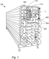
Fig. 1 is a perspective view of a tubular heat exchanger. -
Fig. 2a is an exploded view of a coupling arrangement. -
Fig. 2b is a perspective view of the coupling arrangement. -
Fig. 3 is a cross-sectional view of the coupling arrangement attached to a tube bundle and to a connection pipe. -
Fig. 4 is a detailed cross-sectional view of the coupling arrangement according to a first embodiment. -
Fig. 5 is a detailed cross-sectional view of the coupling arrangement according to a second embodiment. -
Fig. 6 is a detailed cross-sectional view of the coupling arrangement according to a third embodiment. -
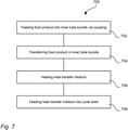
Fig. 7 is a flow chart of a method for heat treating a food product. - With reference to
Fig. 1 atubular heat exchanger 100 that includes acoupling arrangement 1 is shown. Thetubular heat exchanger 100 may be a tubular heat exchanger of the kind named Tetra Spiraflo™, marketed and sold by the company Tetra Pak. - The
tubular heat exchanger 100 has a number oftube bundles 110 that are connected to arespective tube plate 112, for example by welding. Eachtube bundle 110 has anouter shell 302 that encloses thetube bundle 110.Tube bundles 110 are connected to each other viaconnection pipes 304. Food product FP can thereby flow from one tube bundle to another tube bundle. Eachtube bundle 110 comprises a numbers if straight pipes that are arranged in parallel. Theconnection pipes 304 are connected to the tube bundles viacoupling arrangements 1. Theouter shell 302 surrounds thetube bundle 110 such that a heat transfer media HTM, e.g. hot water, can be passed within theouter shell 302 and around thetube bundle 110. - The
tubular heat exchanger 100 may operate under conditions where thecoupling arrangement 1 have shown particularly advantageous, in particular when considering sanitary- and pressure-handling aspects as well as when considering the total cost of thetubular heat exchanger 100. -
Fig. 2a illustrates thecoupling arrangement 1 in further detail. In addition to thetube plate 112, thecoupling arrangement 1 comprises ananchoring ring 202, a retainingelement 206 and aflange 208. Thetube plate 112 can be arranged to be placed within theflange 208 and theanchoring ring 202 IS arranged to be placed over thetube plate 112 and attached to theflange 208. Theanchoring ring 202 can be provided withholes 210 for fastening means for this purpose. - The
tube plate 112 is be provided withholes 212 such the food product can be fed via theseholes 212 into thetube bundle 110. The tubes if the tube bundle is typically inserted into theholes 212 and then welded to thetube plate 212. Further, thetube plate 112 has anend section 214 arranged to be inserted into theflange 208 and atop section 216 around which the outer shell is arranged. - The
end portion 214 has agroove 218 formed in asurface 220 of thetube plate 112. The surface is typically the peripheral surface of thetube plate 112 and the groove may form a circumferential groove in thetube plate 112. The retainingelement 214 can be arranged to be placed in thegroove 218 and it can be divided into afirst part 222 and asecond part 224. - As illustrated, these two
parts groove 218. Each of the twoparts parts parts parts - The
flange 208 can haveholes 226 arranged to receive the fastening means fed through theholes 210 of theanchoring ring 202 such that, in mounted state, theanchoring ring 202 can abut theflange 208 as illustrated infig. 2b . Thetube plate 112 can have a first O-ring groove 228 and a second O-ring groove 230. This is advantageous in that a so-called floating design can be achieved for theshell tube 302, which will be further described below. - The
flange 208 can be provided with agroove 232 arranged to accommodate the retainingelement 206. Thus, by having part of the retainingelement 206 provided in thefirst groove 218 in thetube plate 112 and part of the retainingelement 206 provided in thegroove 232, thetube plate 112 can be held in place via the retainingelement 206 when theanchoring ring 208 is attached to theflange 206. -
Fig. 3 illustrates a cross-sectional view of thecoupling arrangement 1 in the assembled state. - An
outer shell 302 surrounds thetube bundle 110 such that the heat transfer media HTM, such as hot water, can be fed between thetube bundle 110 and theouter shell 302. Further, aconnection pipe 304 is be attached to theflange 208, and fastening means 306a, 306b, such as bolts, can be used for attaching theflange 208 to theanchoring ring 202. Theholes 210 of theanchoring ring 202 may be provided with threads for this purpose. This is advantageous in that the fastening means 306a, 306b can be mounted without the need to reach behind theanchoring ring 202. - To provide for the floating design, that is, allowing the
tube bundle 110 to move axially due to heat expansion and retraction, a first O-ring 308a can be provided in the first O-ring groove 228, and a second O-ring 308b can be provided in the second O-ring groove 230. By having these two O-rings, a risk of leakage of the heat transfer media HTM can be reduced. - The retaining
element 206 can be held between thetube plate 112, theanchoring ring 202 and theflange 208 as described above and illustrated inFig 3 , i.e. it may be located in thegroove 232 in theflange 208. In theflange 208, aseal groove 309 may be provided for accommodating a sealing 310. By the help of this sealing 310 a leakage tight fit between thetube plate 112 and theflange 208 can be achieved. - As illustrated and as described above, part of the retaining
element 206 can be accommodated in thefirst groove 218 of thetube plate 112 and part of the retainingelement 206 can be accommodated in thesecond groove 232 formed by the anchoringring 202 and theflange 208 in combination. More particularly, aninner section 311 of the retainingelement 206 may be accommodated in thefirst groove 218 and anouter section 312 can be accommodated in thesecond groove 232. Thesecond groove 232 can have a radial retainingelement abutment surface 313, facing the retainingelement 214 radially and extending axially. In this way the radial retainingelement abutment surface 313 can interact with aperipheral surface 315 of the retainingelement 214. As described above, the retainingelement 214 can be split in two parts, thefirst part 222 and thesecond part 224. As the pressure P inside thetube bundle 110 increases, these two parts cannot move apart since theflange 208 holds them back in the radial direction R. - In addition, the
flange 208 has an axial retainingelement abutment surface 314, facing the retainingelement 214 axially and extending radially. Further, theflange 208 can further be provided with a radial tubeplate abutment surface 316, facing thetube plate 112 radially and extending axially, and an axial tubeplate abutment surface 318, facing thetube plate 112 axially and extending radially. An advantage with the axial tubeplate abutment surface 318 is that this can be arranged to prevent movement of thetube plate 112 in the axial direction A such that a force F exerted by thetube plate 112 onto the sealing 310 is reduced. - The
anchoring ring 202 may have an axial retainingelement abutment surface 319 provided opposite to the axial retainingelement abutment surface 314. The axial retainingelement abutment surface 314 and the opposite axial retainingelement abutment surface 319 provide for that the retainingelement 206 is prevented to move in the axial direction A. - As illustrated, the
second groove 232 comprises the radial retainingelement abutment surface 313 and the axial retainingelement abutment surface 314, and the opposite axial retainingelement abutment surface 319 is part of theanchoring ring 202. This is however only one out of several possibilities how asecond groove section 320, that is, a section of thecoupling arrangement 1 in which thesecond groove 232 is provided, can be embodied. Other possibilities are illustrated infig. 5 and 6 , and will be described below. -
Fig. 4 illustrates how forces can be formed due to the pressure P of the food product FP inside thetube bundle 110. As illustrated, a tube plate force FT formed by the pressure P inside thetube bundle 110 can be exerted onto aninner section 311 of the retainingelement 206. The tube plate force FT can be transferred via thetube plate 112 and an inner axial retainingelement abutment surface 400 of thefirst groove 218. A radial force FRa may also be formed by the pressure P and transferred via thetube plate 112. As illustrated, the radial force FRa can provide for that the retaining element 124 is pushed onto the radial retainingelement abutment surface 313. In addition, due to the tube plate force FT, the retainingelement 206 may pushed towards the anchoringring 202, more particularly the opposite axial retainingelement surface 319 of theanchoring ring 202, such that an anchoring ring force FRi is formed. Even though not illustrated, other forces may be exerted onto the retainingelement 206. - As illustrated in
fig. 3 and4 , the radial retainingelement abutment surface 313 may be formed by theflange 208. Another option, illustrated infig. 5 , is that that this surface is formed partly by theflange 208 and partly by the anchoringring 202. Still an option, illustrated infig. 6 , is that the radial retainingelement abutment surface 313 is formed by the anchoringring 202 solely. This means that the groove that accommodates theouter section 312 of the retainingelement 206 may be either formed in the flange 208 (Figs 3 and4 ), in theflange 208 in combination with the anchoring ring 202 (Fig. 5 ), or in the anchoring ring 202 (Fig. 6 ). - Further, as illustrated in
fig. 6 , an inner section depth ISD of theinner section 311 may be less than an outer section depth OSD of theouter section 312. This applies for all embodiments described herein. - Even though referring to different surfaces herein as abutment surfaces, this should not be understood as that the retaining
element 206 at all times is in contact with these surfaces, but instead it should be understood as that the surfaces are arranged to abut the retainingelement 206 if conditions require for holding the retainingelement 206 in place, that is, holding the retainingelement 214 within the first andsecond groove -
Fig. 7 is a flow chart comprising steps of amethod 700 for heat treating the food product FP. The method may be performed with thetubular heat exchanger 100. In afirst step 702 of the method, the food product FP is fed from theconnection pipe 304 into thetube bundle 110 of thetubular heat exchanger 100 via thecoupling arrangement 1 described above. In asecond step 704, the food product FP can be transferred from through thetube bundle 110. In athird step 706, the heat transfer medium HTM can be heated. In afourth step 708, which may occur at the same time as thesecond step 704, the heat transfer media HTM can be fed into theouter shell 302 which encloses thetube bundle 110 such that the food product FP is heated to reduce microorganisms in the food product FP, i.e. reduce a number of microorganisms in the food product FP that may otherwise lead to health issues for consumers. The pressure P inside thetube bundle 110 may be above 200 bar and a pressure P' in theouter shell 302 may be below 30 bar. - From the description above follows that, although various embodiments of the invention have been described and shown, the invention is not restricted thereto, but may also be embodied in other ways within the scope of the subject-matter defined in the following claims.
Claims (11)
- A coupling arrangement (1) comprisinga tube plate (112) arranged to be attached to a tube bundle (110),a first groove (218) formed in a surface (220) of the tube plate (112),a flange (208) arranged to accommodate an end section (214) of the tube plate (112), and provided with holes (226) for receiving fastening means (306a, 306b),an anchoring ring (202) arranged to be placed around the tube plate (112) and provided with holes (210) for receiving the fastening means (306a, 306b) for attachment to the flange (208),a retaining element (206) comprising an inner section (311) and an outer section (312), wherein the inner section (311) is arranged be placed in the first groove (218) of the tube plate (112), wherein the retaining element (206) comprises a first part (222) and a second part (224), anda second groove (232) formed by the flange (208) and the anchoring ring (202) in combination, and arranged to accommodate the outer section (312) of the retaining element (206).
- The coupling arrangement (1) according to claim 1, wherein each of the first part (222) and the second part (224) of the retaining element (206) has a semi annular shape.
- The coupling arrangement (1) according to claim 1 or 2, wherein at least one of the flange (208) and the anchoring ring (202) is provided with a radial retaining element abutment surface (313) for preventing radial movement of the retaining element (206) when the anchoring ring (202) is attached to the flange (208).
- The coupling arrangement (1) according to any one of the preceding claims, wherein the flange (208) is provided with a radial tube plate abutment surface (316) and an axial tube plate abutment surface (318) arranged to face the tube plate (112).
- The coupling arrangement (1) according to claim 4, wherein the flange (208) is provided with a seal groove (309) arranged to accommodate a sealing (310), wherein the axial tube plate abutment surface (318) is arranged to prevent movement of the tube plate (112) in an axial direction (A), thereby reducing a force (F) exerted by the tube plate (112) onto the sealing (310).
- The coupling arrangement (1) according to any one of the preceding claims, wherein an outer section depth (OSD) of the outer section (312) is greater than an inner section depth (ISD) of the inner section (311) of the retaining element (206).
- The coupling arrangement (1) according to any one of the preceding claims, wherein the fastening means (306a, 306b) and the holes (210) of the anchoring ring (202) are threaded and arranged to interact for attaching the anchoring ring (202) to the flange (208).
- A tubular heat exchanger (100) comprisinga coupling arrangement (1) according to any one of the preceding claims,a tube bundle (110) comprising a number of tubes that are attached to the tube plate (112) and arranged to transfer a food product (FP), andan outer shell (302) arranged to enclose the tube bundle (110) and a heat transfer medium (HTM), anda pipe (304) attached to the flange (208).
- A method (700) for heat treating a food product (FP) with a tubular heat exchanger according to claim 8, wherein the food product has a viscosity greater than 100 cP at temperature of 40 °C, said method comprisingfeeding (702) the food product (FP) from the pipe (304) into the tube bundle (110) via the coupling arrangement (1),transferring (704) the food product (FP) through the tube bundle (110),heating (706) a heat transfer medium (HTM), andfeeding (708) the heat transfer medium (HTM) into the outer shell (302), such that the food product (FP) is heated to reduce microorganisms in the food product (FP).
- The method according to claim 9, wherein a pressure (P) inside the tubes of the tube bundle (110) is above 200 bar.
- The method according to claim 9 or 10, wherein a pressure (P') in the outer shell (302) is below 30 bar.
Applications Claiming Priority (1)
| Application Number | Priority Date | Filing Date | Title |
|---|---|---|---|
| EP20195443 | 2020-09-10 |
Publications (2)
| Publication Number | Publication Date |
|---|---|
| EP3967962A1 true EP3967962A1 (en) | 2022-03-16 |
| EP3967962B1 EP3967962B1 (en) | 2023-08-23 |
Family
ID=72470253
Family Applications (1)
| Application Number | Title | Priority Date | Filing Date |
|---|---|---|---|
| EP21195805.3A Active EP3967962B1 (en) | 2020-09-10 | 2021-09-09 | A coupling arrangement, a tubular heat exchanger and a method for heat treating a food product |
Country Status (3)
| Country | Link |
|---|---|
| EP (1) | EP3967962B1 (en) |
| CN (1) | CN116113802B (en) |
| WO (1) | WO2022053571A1 (en) |
Citations (6)
| Publication number | Priority date | Publication date | Assignee | Title |
|---|---|---|---|---|
| US4119141A (en) * | 1977-05-12 | 1978-10-10 | Thut Bruno H | Heat exchanger |
| US4573527A (en) * | 1983-07-29 | 1986-03-04 | Mcdonough M J | Heat exchanger closure connection |
| DE9403913U1 (en) * | 1994-03-09 | 1994-05-05 | Gea Finnah Gmbh | Tube bundle heat exchanger |
| DE102005059463A1 (en) * | 2005-12-13 | 2007-06-14 | Tuchenhagen Dairy Systems Gmbh | Device for influencing the flow in the region of a tube carrier plate of a tube bundle heat exchanger |
| EP2607833A1 (en) * | 2011-12-22 | 2013-06-26 | Tetra Laval Holdings & Finance S.A. | A module for improved running time in tubular heat exchangers |
| DE202020000985U1 (en) * | 2020-03-11 | 2020-04-06 | Gea Tds Gmbh | Auxiliary device for a method for welding connections between inner tubes and tube support plates of a tube bundle for a product-to-product tube bundle heat exchanger |
Family Cites Families (5)
| Publication number | Priority date | Publication date | Assignee | Title |
|---|---|---|---|---|
| CN206092963U (en) * | 2016-10-19 | 2017-04-12 | 邢德君 | Subdivision composite seal |
| CN111480023B (en) * | 2017-12-20 | 2023-04-14 | 利乐拉瓦尔集团及财务有限公司 | Seal and tubular heat exchanger using the same |
| CN109538854B (en) * | 2019-01-17 | 2024-04-19 | 四川省安科技术咨询有限公司 | Automatic alarming equipotential bridging device for flange leakage |
| CN210036404U (en) * | 2019-04-30 | 2020-02-07 | 中国五环工程有限公司 | Shell side combined sealing structure of hairpin type heat exchanger |
| CN110455110A (en) * | 2019-09-05 | 2019-11-15 | 福建福清核电有限公司 | A portable incomplete core-pulling device for heat exchangers |
-
2021
- 2021-09-09 EP EP21195805.3A patent/EP3967962B1/en active Active
- 2021-09-09 CN CN202180061838.XA patent/CN116113802B/en active Active
- 2021-09-09 WO PCT/EP2021/074845 patent/WO2022053571A1/en not_active Ceased
Patent Citations (6)
| Publication number | Priority date | Publication date | Assignee | Title |
|---|---|---|---|---|
| US4119141A (en) * | 1977-05-12 | 1978-10-10 | Thut Bruno H | Heat exchanger |
| US4573527A (en) * | 1983-07-29 | 1986-03-04 | Mcdonough M J | Heat exchanger closure connection |
| DE9403913U1 (en) * | 1994-03-09 | 1994-05-05 | Gea Finnah Gmbh | Tube bundle heat exchanger |
| DE102005059463A1 (en) * | 2005-12-13 | 2007-06-14 | Tuchenhagen Dairy Systems Gmbh | Device for influencing the flow in the region of a tube carrier plate of a tube bundle heat exchanger |
| EP2607833A1 (en) * | 2011-12-22 | 2013-06-26 | Tetra Laval Holdings & Finance S.A. | A module for improved running time in tubular heat exchangers |
| DE202020000985U1 (en) * | 2020-03-11 | 2020-04-06 | Gea Tds Gmbh | Auxiliary device for a method for welding connections between inner tubes and tube support plates of a tube bundle for a product-to-product tube bundle heat exchanger |
Also Published As
| Publication number | Publication date |
|---|---|
| CN116113802B (en) | 2026-02-13 |
| CN116113802A (en) | 2023-05-12 |
| EP3967962B1 (en) | 2023-08-23 |
| WO2022053571A1 (en) | 2022-03-17 |
Similar Documents
| Publication | Publication Date | Title |
|---|---|---|
| US5043797A (en) | Cooling header connection for a thyristor stack | |
| JP5327983B2 (en) | Pipe assembly | |
| US4244423A (en) | Heat exchanger | |
| US4119141A (en) | Heat exchanger | |
| US4525916A (en) | Method of coupling coaxial shafts | |
| AU2016381244A1 (en) | Adapter coupling | |
| US4239462A (en) | Heat barrier for motor-pump aggregates | |
| PL60452Y1 (en) | Clamp-type pipe joint | |
| EP3967962B1 (en) | A coupling arrangement, a tubular heat exchanger and a method for heat treating a food product | |
| EP0727026B1 (en) | Pipe connector | |
| US6199254B1 (en) | Swaging tool with multiple pushers | |
| US3593782A (en) | Heat exchanger | |
| US8006748B2 (en) | Sealing arrangement for internal tubesheet for tubular heat exchangers | |
| CN109996985B (en) | Seal assembly | |
| EP4279788B1 (en) | Push-fitting | |
| US12392436B2 (en) | Connector and method for connecting pipes for transporting fluids | |
| EP3728928B1 (en) | Assembly for engaging the interior of a pipe | |
| EP2013559B1 (en) | Seal for tubular heat exchanger | |
| JP2021523333A (en) | Fluid connection devices and systems | |
| CN112985124A (en) | Aseptic tubular heat exchanger | |
| EP3252363B1 (en) | Coupling arrangement for connecting two pipe sections | |
| EP4127538B1 (en) | Restraining pipe coupling | |
| EP3293430B1 (en) | Articulating coupling assembly | |
| WO2007019551A2 (en) | A jacketed hose assembly and method | |
| TW202536324A (en) | Improved male fluid connector for a quick connecting and disconnecting fluid coupling |
Legal Events
| Date | Code | Title | Description |
|---|---|---|---|
| PUAI | Public reference made under article 153(3) epc to a published international application that has entered the european phase |
Free format text: ORIGINAL CODE: 0009012 |
|
| STAA | Information on the status of an ep patent application or granted ep patent |
Free format text: STATUS: THE APPLICATION HAS BEEN PUBLISHED |
|
| AK | Designated contracting states |
Kind code of ref document: A1 Designated state(s): AL AT BE BG CH CY CZ DE DK EE ES FI FR GB GR HR HU IE IS IT LI LT LU LV MC MK MT NL NO PL PT RO RS SE SI SK SM TR |
|
| STAA | Information on the status of an ep patent application or granted ep patent |
Free format text: STATUS: REQUEST FOR EXAMINATION WAS MADE |
|
| 17P | Request for examination filed |
Effective date: 20220916 |
|
| RBV | Designated contracting states (corrected) |
Designated state(s): AL AT BE BG CH CY CZ DE DK EE ES FI FR GB GR HR HU IE IS IT LI LT LU LV MC MK MT NL NO PL PT RO RS SE SI SK SM TR |
|
| GRAP | Despatch of communication of intention to grant a patent |
Free format text: ORIGINAL CODE: EPIDOSNIGR1 |
|
| STAA | Information on the status of an ep patent application or granted ep patent |
Free format text: STATUS: GRANT OF PATENT IS INTENDED |
|
| INTG | Intention to grant announced |
Effective date: 20230509 |
|
| RIC1 | Information provided on ipc code assigned before grant |
Ipc: F28F 9/02 20060101ALI20230421BHEP Ipc: F28F 9/26 20060101AFI20230421BHEP |
|
| GRAS | Grant fee paid |
Free format text: ORIGINAL CODE: EPIDOSNIGR3 |
|
| GRAA | (expected) grant |
Free format text: ORIGINAL CODE: 0009210 |
|
| STAA | Information on the status of an ep patent application or granted ep patent |
Free format text: STATUS: THE PATENT HAS BEEN GRANTED |
|
| AK | Designated contracting states |
Kind code of ref document: B1 Designated state(s): AL AT BE BG CH CY CZ DE DK EE ES FI FR GB GR HR HU IE IS IT LI LT LU LV MC MK MT NL NO PL PT RO RS SE SI SK SM TR |
|
| REG | Reference to a national code |
Ref country code: GB Ref legal event code: FG4D |
|
| REG | Reference to a national code |
Ref country code: CH Ref legal event code: EP |
|
| REG | Reference to a national code |
Ref country code: DE Ref legal event code: R096 Ref document number: 602021004479 Country of ref document: DE |
|
| REG | Reference to a national code |
Ref country code: IE Ref legal event code: FG4D |
|
| REG | Reference to a national code |
Ref country code: LT Ref legal event code: MG9D |
|
| P01 | Opt-out of the competence of the unified patent court (upc) registered |
Effective date: 20231117 |
|
| REG | Reference to a national code |
Ref country code: NL Ref legal event code: MP Effective date: 20230823 |
|
| REG | Reference to a national code |
Ref country code: AT Ref legal event code: MK05 Ref document number: 1603071 Country of ref document: AT Kind code of ref document: T Effective date: 20230823 |
|
| PG25 | Lapsed in a contracting state [announced via postgrant information from national office to epo] |
Ref country code: GR Free format text: LAPSE BECAUSE OF FAILURE TO SUBMIT A TRANSLATION OF THE DESCRIPTION OR TO PAY THE FEE WITHIN THE PRESCRIBED TIME-LIMIT Effective date: 20231124 |
|
| PG25 | Lapsed in a contracting state [announced via postgrant information from national office to epo] |
Ref country code: IS Free format text: LAPSE BECAUSE OF FAILURE TO SUBMIT A TRANSLATION OF THE DESCRIPTION OR TO PAY THE FEE WITHIN THE PRESCRIBED TIME-LIMIT Effective date: 20231223 |
|
| PG25 | Lapsed in a contracting state [announced via postgrant information from national office to epo] |
Ref country code: SE Free format text: LAPSE BECAUSE OF FAILURE TO SUBMIT A TRANSLATION OF THE DESCRIPTION OR TO PAY THE FEE WITHIN THE PRESCRIBED TIME-LIMIT Effective date: 20230823 Ref country code: RS Free format text: LAPSE BECAUSE OF FAILURE TO SUBMIT A TRANSLATION OF THE DESCRIPTION OR TO PAY THE FEE WITHIN THE PRESCRIBED TIME-LIMIT Effective date: 20230823 Ref country code: PT Free format text: LAPSE BECAUSE OF FAILURE TO SUBMIT A TRANSLATION OF THE DESCRIPTION OR TO PAY THE FEE WITHIN THE PRESCRIBED TIME-LIMIT Effective date: 20231226 Ref country code: NO Free format text: LAPSE BECAUSE OF FAILURE TO SUBMIT A TRANSLATION OF THE DESCRIPTION OR TO PAY THE FEE WITHIN THE PRESCRIBED TIME-LIMIT Effective date: 20231123 Ref country code: NL Free format text: LAPSE BECAUSE OF FAILURE TO SUBMIT A TRANSLATION OF THE DESCRIPTION OR TO PAY THE FEE WITHIN THE PRESCRIBED TIME-LIMIT Effective date: 20230823 Ref country code: LV Free format text: LAPSE BECAUSE OF FAILURE TO SUBMIT A TRANSLATION OF THE DESCRIPTION OR TO PAY THE FEE WITHIN THE PRESCRIBED TIME-LIMIT Effective date: 20230823 Ref country code: LT Free format text: LAPSE BECAUSE OF FAILURE TO SUBMIT A TRANSLATION OF THE DESCRIPTION OR TO PAY THE FEE WITHIN THE PRESCRIBED TIME-LIMIT Effective date: 20230823 Ref country code: IS Free format text: LAPSE BECAUSE OF FAILURE TO SUBMIT A TRANSLATION OF THE DESCRIPTION OR TO PAY THE FEE WITHIN THE PRESCRIBED TIME-LIMIT Effective date: 20231223 Ref country code: HR Free format text: LAPSE BECAUSE OF FAILURE TO SUBMIT A TRANSLATION OF THE DESCRIPTION OR TO PAY THE FEE WITHIN THE PRESCRIBED TIME-LIMIT Effective date: 20230823 Ref country code: GR Free format text: LAPSE BECAUSE OF FAILURE TO SUBMIT A TRANSLATION OF THE DESCRIPTION OR TO PAY THE FEE WITHIN THE PRESCRIBED TIME-LIMIT Effective date: 20231124 Ref country code: FI Free format text: LAPSE BECAUSE OF FAILURE TO SUBMIT A TRANSLATION OF THE DESCRIPTION OR TO PAY THE FEE WITHIN THE PRESCRIBED TIME-LIMIT Effective date: 20230823 Ref country code: AT Free format text: LAPSE BECAUSE OF FAILURE TO SUBMIT A TRANSLATION OF THE DESCRIPTION OR TO PAY THE FEE WITHIN THE PRESCRIBED TIME-LIMIT Effective date: 20230823 |
|
| PG25 | Lapsed in a contracting state [announced via postgrant information from national office to epo] |
Ref country code: PL Free format text: LAPSE BECAUSE OF FAILURE TO SUBMIT A TRANSLATION OF THE DESCRIPTION OR TO PAY THE FEE WITHIN THE PRESCRIBED TIME-LIMIT Effective date: 20230823 |
|
| PG25 | Lapsed in a contracting state [announced via postgrant information from national office to epo] |
Ref country code: ES Free format text: LAPSE BECAUSE OF FAILURE TO SUBMIT A TRANSLATION OF THE DESCRIPTION OR TO PAY THE FEE WITHIN THE PRESCRIBED TIME-LIMIT Effective date: 20230823 |
|
| PG25 | Lapsed in a contracting state [announced via postgrant information from national office to epo] |
Ref country code: SM Free format text: LAPSE BECAUSE OF FAILURE TO SUBMIT A TRANSLATION OF THE DESCRIPTION OR TO PAY THE FEE WITHIN THE PRESCRIBED TIME-LIMIT Effective date: 20230823 Ref country code: RO Free format text: LAPSE BECAUSE OF FAILURE TO SUBMIT A TRANSLATION OF THE DESCRIPTION OR TO PAY THE FEE WITHIN THE PRESCRIBED TIME-LIMIT Effective date: 20230823 Ref country code: ES Free format text: LAPSE BECAUSE OF FAILURE TO SUBMIT A TRANSLATION OF THE DESCRIPTION OR TO PAY THE FEE WITHIN THE PRESCRIBED TIME-LIMIT Effective date: 20230823 Ref country code: EE Free format text: LAPSE BECAUSE OF FAILURE TO SUBMIT A TRANSLATION OF THE DESCRIPTION OR TO PAY THE FEE WITHIN THE PRESCRIBED TIME-LIMIT Effective date: 20230823 Ref country code: DK Free format text: LAPSE BECAUSE OF FAILURE TO SUBMIT A TRANSLATION OF THE DESCRIPTION OR TO PAY THE FEE WITHIN THE PRESCRIBED TIME-LIMIT Effective date: 20230823 Ref country code: CZ Free format text: LAPSE BECAUSE OF FAILURE TO SUBMIT A TRANSLATION OF THE DESCRIPTION OR TO PAY THE FEE WITHIN THE PRESCRIBED TIME-LIMIT Effective date: 20230823 Ref country code: SK Free format text: LAPSE BECAUSE OF FAILURE TO SUBMIT A TRANSLATION OF THE DESCRIPTION OR TO PAY THE FEE WITHIN THE PRESCRIBED TIME-LIMIT Effective date: 20230823 |
|
| PG25 | Lapsed in a contracting state [announced via postgrant information from national office to epo] |
Ref country code: LU Free format text: LAPSE BECAUSE OF NON-PAYMENT OF DUE FEES Effective date: 20230909 |
|
| REG | Reference to a national code |
Ref country code: DE Ref legal event code: R097 Ref document number: 602021004479 Country of ref document: DE |
|
| REG | Reference to a national code |
Ref country code: BE Ref legal event code: MM Effective date: 20230930 |
|
| PG25 | Lapsed in a contracting state [announced via postgrant information from national office to epo] |
Ref country code: LU Free format text: LAPSE BECAUSE OF NON-PAYMENT OF DUE FEES Effective date: 20230909 Ref country code: MC Free format text: LAPSE BECAUSE OF FAILURE TO SUBMIT A TRANSLATION OF THE DESCRIPTION OR TO PAY THE FEE WITHIN THE PRESCRIBED TIME-LIMIT Effective date: 20230823 |
|
| PLBE | No opposition filed within time limit |
Free format text: ORIGINAL CODE: 0009261 |
|
| STAA | Information on the status of an ep patent application or granted ep patent |
Free format text: STATUS: NO OPPOSITION FILED WITHIN TIME LIMIT |
|
| REG | Reference to a national code |
Ref country code: IE Ref legal event code: MM4A |
|
| PG25 | Lapsed in a contracting state [announced via postgrant information from national office to epo] |
Ref country code: IE Free format text: LAPSE BECAUSE OF NON-PAYMENT OF DUE FEES Effective date: 20230909 |
|
| 26N | No opposition filed |
Effective date: 20240524 |
|
| PG25 | Lapsed in a contracting state [announced via postgrant information from national office to epo] |
Ref country code: IE Free format text: LAPSE BECAUSE OF NON-PAYMENT OF DUE FEES Effective date: 20230909 Ref country code: SI Free format text: LAPSE BECAUSE OF FAILURE TO SUBMIT A TRANSLATION OF THE DESCRIPTION OR TO PAY THE FEE WITHIN THE PRESCRIBED TIME-LIMIT Effective date: 20230823 |
|
| PG25 | Lapsed in a contracting state [announced via postgrant information from national office to epo] |
Ref country code: BE Free format text: LAPSE BECAUSE OF NON-PAYMENT OF DUE FEES Effective date: 20230930 |
|
| PG25 | Lapsed in a contracting state [announced via postgrant information from national office to epo] |
Ref country code: BG Free format text: LAPSE BECAUSE OF FAILURE TO SUBMIT A TRANSLATION OF THE DESCRIPTION OR TO PAY THE FEE WITHIN THE PRESCRIBED TIME-LIMIT Effective date: 20230823 |
|
| PG25 | Lapsed in a contracting state [announced via postgrant information from national office to epo] |
Ref country code: BG Free format text: LAPSE BECAUSE OF FAILURE TO SUBMIT A TRANSLATION OF THE DESCRIPTION OR TO PAY THE FEE WITHIN THE PRESCRIBED TIME-LIMIT Effective date: 20230823 |
|
| REG | Reference to a national code |
Ref country code: CH Ref legal event code: PL |
|
| PG25 | Lapsed in a contracting state [announced via postgrant information from national office to epo] |
Ref country code: CH Free format text: LAPSE BECAUSE OF NON-PAYMENT OF DUE FEES Effective date: 20240930 |
|
| PG25 | Lapsed in a contracting state [announced via postgrant information from national office to epo] |
Ref country code: CY Free format text: LAPSE BECAUSE OF FAILURE TO SUBMIT A TRANSLATION OF THE DESCRIPTION OR TO PAY THE FEE WITHIN THE PRESCRIBED TIME-LIMIT; INVALID AB INITIO Effective date: 20210909 |
|
| PG25 | Lapsed in a contracting state [announced via postgrant information from national office to epo] |
Ref country code: HU Free format text: LAPSE BECAUSE OF FAILURE TO SUBMIT A TRANSLATION OF THE DESCRIPTION OR TO PAY THE FEE WITHIN THE PRESCRIBED TIME-LIMIT; INVALID AB INITIO Effective date: 20210909 |
|
| PGFP | Annual fee paid to national office [announced via postgrant information from national office to epo] |
Ref country code: DE Payment date: 20250926 Year of fee payment: 5 |
|
| PGFP | Annual fee paid to national office [announced via postgrant information from national office to epo] |
Ref country code: IT Payment date: 20250922 Year of fee payment: 5 |
|
| PGFP | Annual fee paid to national office [announced via postgrant information from national office to epo] |
Ref country code: FR Payment date: 20250925 Year of fee payment: 5 |
|
| PG25 | Lapsed in a contracting state [announced via postgrant information from national office to epo] |
Ref country code: TR Free format text: LAPSE BECAUSE OF FAILURE TO SUBMIT A TRANSLATION OF THE DESCRIPTION OR TO PAY THE FEE WITHIN THE PRESCRIBED TIME-LIMIT Effective date: 20230823 |